installation instructions rear vision system – … · 9002-9002-00 2 march 2011 1 of 7 rear...
TRANSCRIPT
INSTALLATION INSTRUCTIONS
9002-9002-00 2 March 2011
1 of 7
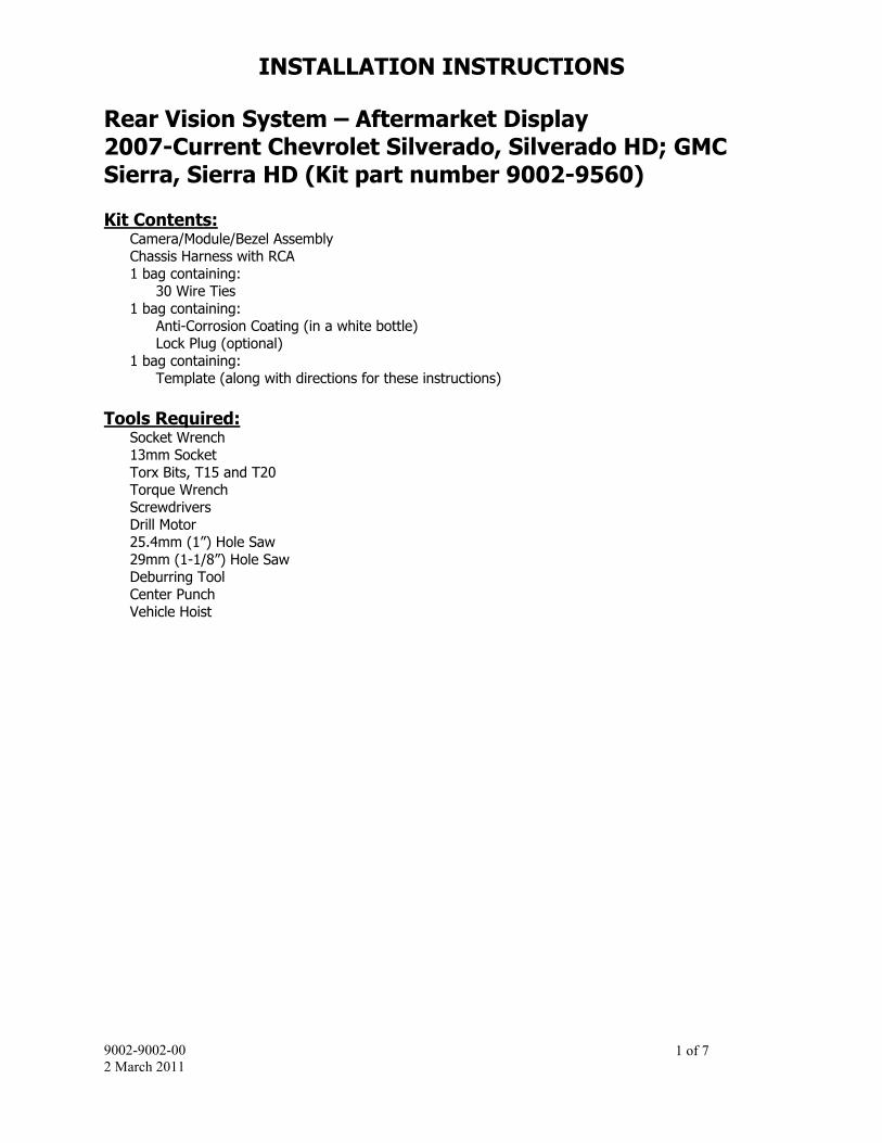
Rear Vision System – Aftermarket Display 2007-Current Chevrolet Silverado, Silverado HD; GMC Sierra, Sierra HD (Kit part number 9002-9560) Kit Contents:
Camera/Module/Bezel Assembly Chassis Harness with RCA 1 bag containing:
30 Wire Ties 1 bag containing:
Anti-Corrosion Coating (in a white bottle) Lock Plug (optional) 1 bag containing: Template (along with directions for these instructions)
Tools Required:
Socket Wrench 13mm Socket Torx Bits, T15 and T20 Torque Wrench Screwdrivers Drill Motor 25.4mm (1”) Hole Saw 29mm (1-1/8”) Hole Saw Deburring Tool Center Punch Vehicle Hoist
INSTALLATION INSTRUCTIONS
9002-9002-00 2 March 2011
2 of 7
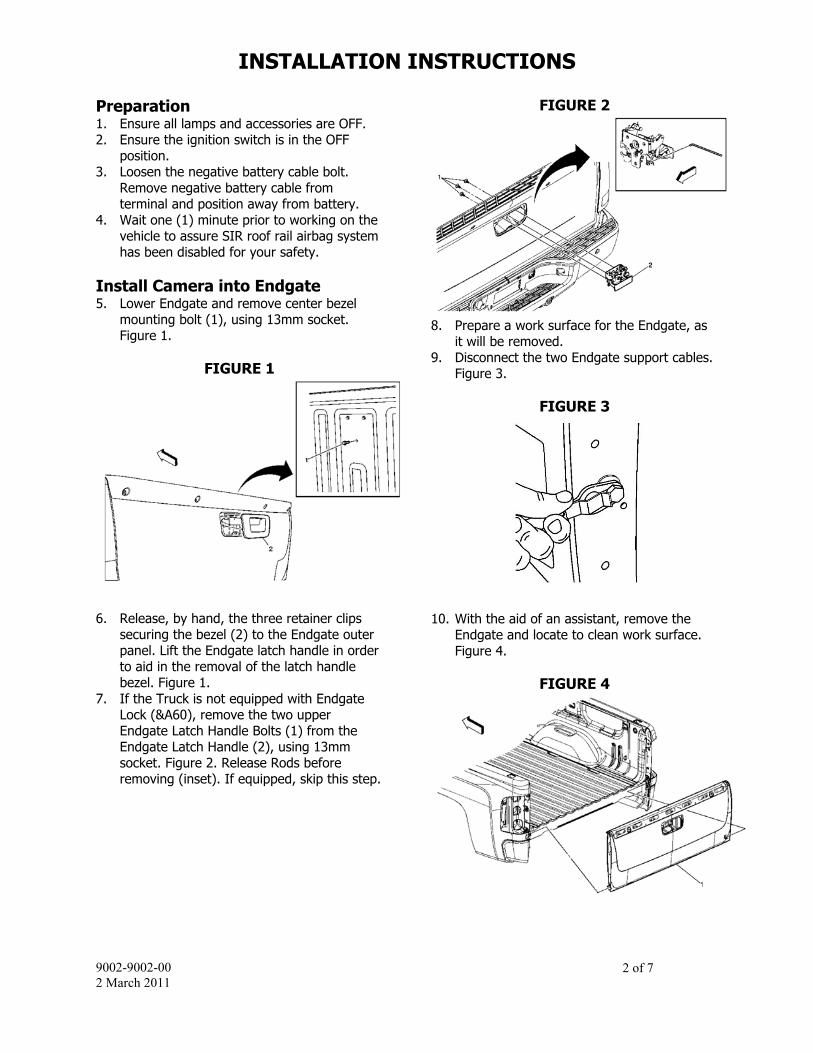
Preparation 1. Ensure all lamps and accessories are OFF. 2. Ensure the ignition switch is in the OFF
position. 3. Loosen the negative battery cable bolt.
Remove negative battery cable from terminal and position away from battery.
4. Wait one (1) minute prior to working on the vehicle to assure SIR roof rail airbag system has been disabled for your safety.
Install Camera into Endgate 5. Lower Endgate and remove center bezel
mounting bolt (1), using 13mm socket. Figure 1.
FIGURE 1
6. Release, by hand, the three retainer clips
securing the bezel (2) to the Endgate outer panel. Lift the Endgate latch handle in order to aid in the removal of the latch handle bezel. Figure 1.
7. If the Truck is not equipped with Endgate Lock (&A60), remove the two upper Endgate Latch Handle Bolts (1) from the Endgate Latch Handle (2), using 13mm socket. Figure 2. Release Rods before removing (inset). If equipped, skip this step.
FIGURE 2
8. Prepare a work surface for the Endgate, as
it will be removed. 9. Disconnect the two Endgate support cables.
Figure 3.
FIGURE 3
10. With the aid of an assistant, remove the
Endgate and locate to clean work surface. Figure 4.
FIGURE 4

INSTALLATION INSTRUCTIONS
9002-9002-00 2 March 2011
3 of 7
11. Locate the supplied Template Sheet for the Endgate and Pickup Box Sill. Note: For Model Year 2009 and forward, some vehicles may already have a flanged hole, in this location. If this is the case, remove the flange from the front side of the sill and skip to step 16.
12. Cut out Endgate Template and attach to Endgate using tape. Using the Center Punch, mark the center of hole.
13. Cut out Sill Plate Template and attach to Pickup Box Sill using tape. Using the Center Punch, mark the center of hole.
14. Using a drill motor and a 29mm (1-1/8”) Hole Saw, cut out the harness pass-through in the Endgate. Figure 5.
FIGURE 5
15. Using a drill motor and a 29mm (1-1/8”)
Hole Saw, cut out the harness pass-through in the Pickup Box Sill. Figure 6.
FIGURE 6
16. Clean rough edges using a deburring tool. 17. Lubricate the two cut outs with the provided
Anti-Corrosion Coating. 18. Locate the provided Rear Vision Camera
Bezel Assembly. Figure 7.
FIGURE 7
19. If the Truck is equipped with a factory
Endgate Lock, remove the lock cylinder from the original Endgate Bezel. Remove the Endgate Lock Cylinder Retaining Clip (1) and then the Endgate Lock Cylinder (2). Figure 8.
FIGURE 8
20. If equipped, insert the Endgate Lock
Cylinder (2) into the new Endgate Bezel and re-attach the Endgate Lock Cylinder Retaining Clip (1). Figure 8. a. If the Truck is not equipped with factory
Endgate Lock, install Lock Plug. b. If locking features are desired an
Endgate Latch Handle (part number 25775280) and an Endgate Lock Cylinder (part numer 25775278) are available through GM dealer.
21. Install the new Endgate Bezel Assembly, by first routing the Camera Assembly harness pigtail through the Endgate Bezel opening down through the Endgate to the 29mm hole at the bottom of the Endgate. Figure 9.

INSTALLATION INSTRUCTIONS
9002-9002-00 2 March 2011
4 of 7
FIGURE 9
22. Pull connector (2), first grommet (3), and
second grommet (4) through new Endgate (1) pass-through. Figure 10.
FIGURE 10
23. Snap the Endgate Bezel Assembly into the
Endgate. 24. Seat the second grommet (4) securely
around opening. Figure 10. 25. Install remaining Endgate Latch Handle Bolt
in Endgate and tighten all three 13mm bolts to 25 N·m (18 lb ft).
26. If present, remove the Rear License Plate. 27. With the help of an Assistant, re-install the
Endgate onto the Pickup Box, carefully routing the Camera harness through the opening on the Pickup Box Sill.
28. Re-attach Endgate Support Cables and close Endgate. Figure 11.
FIGURE 11
29. Through the License Plate Opening pull the
Camera Assembly Harness (2) until the first grommet (3) is properly seated in the Pickup Box Sill (1). Figure 12.
FIGURE 12
Cut Accessory Pass-Through in Front-of-Dash 30. Remove Left Instrument Panel Outer Trim
Cover (1). Figure 13.

INSTALLATION INSTRUCTIONS
9002-9002-00 2 March 2011
5 of 7
FIGURE 13
31. Remove the Parking Brake Release Handle
Bolt and then the Handle. Remove the two Knee Bolster Assembly Screws (1) and the Knee Bolster Assembly (2). Figure 14.
FIGURE 14
32. Disconnect the electrical connections, if
applicable. 33. Remove the M-BEC cover. 34. Disengage the M-BEC (1) from support
bracket. Figure 15.
FIGURE 15
35. Relocate M-BEC up into the IP to gain
access to Front-of-Dash Matte Opening behind M-BEC.
36. Locate cut-out in dash matte. Locate the dimple in the sheet metal and then use a center punch to help start a drill bit as close as possible to dimple. Using a drill motor and a 25.4mm (1”) hole saw, drill out the chassis harness pass-through (2). Figure 16.
FIGURE 16
37. If this location is occupied by Trailer Brakes
(&JL1) or another Accessory, drill a new Chassis Harness pass-through (3) between the IP Harness (1) and Trailer Brake (2) pass-through grommets. Figure 16.
38. Clean rough edges using a deburring tool. Figure 16.
39. Apply Anti-Corrosion Coating to the opening. Figure 16.

INSTALLATION INSTRUCTIONS
9002-9002-00 2 March 2011
6 of 7
40. If needed, install aftermarket display/ Navigation display as per instructions.
41. Connect the male RCA from the chassis harness to the camera IN on the aftermarket display/ Navigation display.
42. Connect the remainder of the leads from the chassis harness as per Chart A on vehicle wiring.
Chart A
Color Polarity Purpose Connect to
Green + Reverse Reverse lamp trigger
Pink + Ignition
Ignition Controlled power
Black - Ground Chassis White - Shield Chassis RCA AC Video Out Monitor
CHART B (REFERENCE ONLY)
Camera and Chassis Harness Pinout
PIN NO NAME
CAMERA HARNES COLOR
CHASSIS HARNESS COLOR
1 Video Signal
Yellow Gray/Dark Blue
2 Shield White White
3 Backup Lamp
Blue Green
4 Video Ground
Brown Gray/Orange
5 Power Ground
Black Black
6 Ignition Red Pink
43. Re-install the Knee Bolster Assembly.
Tighten Screws to 2 N·m (18 lb in). Re-install Parking Brake Release Handle and Bolt, tighten to 9 N·m (80 lb in). Figure 14.
44. Re-install Instrument Panel Outer Trim Cover. See Figure 13.
Chassis Harness Install 45. Locate the provided Rear Vision Camera
Chassis Harness with RCA. 46. Route the grommet-end of the Chassis
Harness through the Driver’s Side Wheel Housing and then through the opening in the Front-of-Dash. Figure 17.
FIGURE 17
47. From the inside of the cab pull the Chassis
Harness through until the grommet is properly seated.
48. Connect the Chassis Harness RCA to the Camera Input of the Aftermarket Radio and secure harnesses with wire ties.
49. Install the MBEC into the Support Bracket. Figure 15.
50. Install the MBEC cover onto the MBEC. 51. Raise the Truck up on a hoist to route the
Chassis Harness. 52. Route the Harness, working towards the
rear of the vehicle, along the existing Chassis Harness, routing away from Body Mounts.
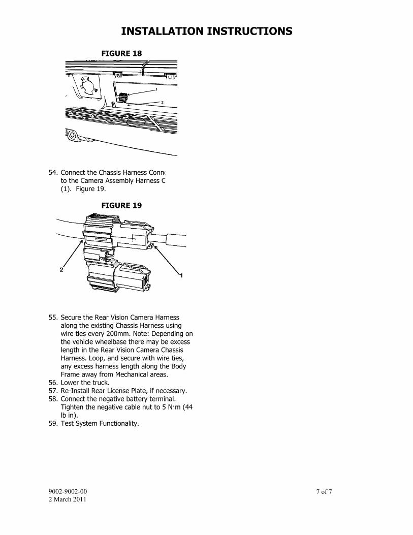
53. Clip the Chassis Harness (1) onto the lower License Plate frame (2), orientating the plug below the primary connector and being 25mm from the corner. Figure 18.
INSTALLATION INSTRUCTIONS
9002-9002-00 2 March 2011
7 of 7
FIGURE 18
54. Connect the Chassis Harness Connector (2)
to the Camera Assembly Harness Connector (1). Figure 19.
FIGURE 19
55. Secure the Rear Vision Camera Harness
along the existing Chassis Harness using wire ties every 200mm. Note: Depending on the vehicle wheelbase there may be excess length in the Rear Vision Camera Chassis Harness. Loop, and secure with wire ties, any excess harness length along the Body Frame away from Mechanical areas.
56. Lower the truck. 57. Re-Install Rear License Plate, if necessary. 58. Connect the negative battery terminal.
Tighten the negative cable nut to 5 N·m (44 lb in).
59. Test System Functionality.