installation manual 6” suspension system 1999 - 2005 chevy ... · part # 16955 1999 - 2005 chevy...
TRANSCRIPT
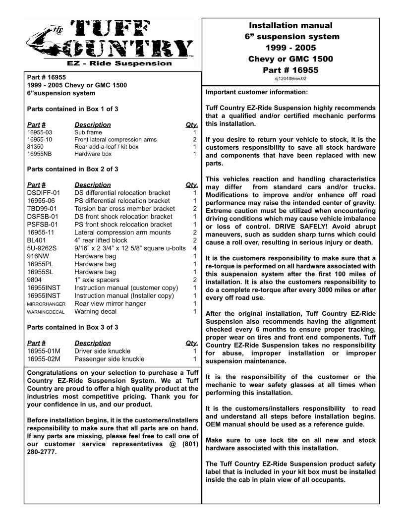
Part # 169551999 - 2005 Chevy or GMC 15006”suspension system
Parts contained in Box 1 of 3
Part # Description Qty.16955-03 Sub frame 116955-10 Front lateral compression arms 281350 Rear add-a-leaf / kit box 116955NB Hardware box 1
Parts contained in Box 2 of 3
Part # Description Qty.DSDIFF-01 DS differential relocation bracket 116955-06 PS differential relocation bracket 1TBD99-01 Torsion bar cross member bracket 2DSFSB-01 DS front shock relocation bracket 1PSFSB-01 PS front shock relocation bracket 116955-11 Lateral compression arm mounts 2BL401 4” rear lifted block 25U-9262S 9/16” x 2 3/4” x 12 5/8” square u-bolts 4916NW Hardware bag 116955PL Hardware bag 116955SL Hardware bag 19804 1” axle spacers 216955INST Instruction manual (customer copy) 116955INST Instruction manual (Installer copy) 1MIRRORHANGER Rear view mirror hanger 1WARNINGDECAL Warning decal 1
Parts contained in Box 3 of 3
Part # Description Qty.16955-01M Driver side knuckle 116955-02M Passenger side knuckle 1
Congratulations on your selection to purchase a TuffCountry EZ-Ride Suspension System. We at TuffCountry are proud to offer a high quality product at theindustries most competitive pricing. Thank you foryour confidence in us, and our product.
Before installation begins, it is the customers/installersresponsibility to make sure that all parts are on hand.If any parts are missing, please feel free to call one ofour customer service representatives @ (801)280-2777.
Installation manual6” suspension system
1999 - 2005 Chevy or GMC 1500
Part # 16955sj120409rev.02
Important customer information:
Tuff Country EZ-Ride Suspension highly recommendsthat a qualified and/or certified mechanic performsthis installation.
If you desire to return your vehicle to stock, it is thecustomers responsibility to save all stock hardwareand components that have been replaced with newparts.
This vehicles reaction and handling characteristicsmay differ from standard cars and/or trucks.Modifications to improve and/or enhance off roadperformance may raise the intended center of gravity.Extreme caution must be utilized when encounteringdriving conditions which may cause vehicle imbalanceor loss of control. DRIVE SAFELY! Avoid abruptmaneuvers, such as sudden sharp turns which couldcause a roll over, resulting in serious injury or death.
It is the customers responsibility to make sure that are-torque is performed on all hardware associated withthis suspension system after the first 100 miles ofinstallation. It is also the customers responsibility todo a complete re-torque after every 3000 miles or afterevery off road use.
After the original installation, Tuff Country EZ-RideSuspension also recommends having the alignmentchecked every 6 months to ensure proper tracking,proper wear on tires and front end components. TuffCountry EZ-Ride Suspension takes no responsibilityfor abuse, improper installation or impropersuspension maintenance.
It is the responsibility of the customer or themechanic to wear safety glasses at all times whenperforming this installation.
It is the customers/installers responsibility to readand understand all steps before installation begins.OEM manual should be used as a reference guide.
Make sure to use lock tite on all new and stockhardware associated with this installation.
The Tuff Country EZ-Ride Suspension product safetylabel that is included in your kit box must be installedinside the cab in plain view of all occupants.

Limited lifetime warranty
Notice to all Tuff Country EZ-Ride Suspensioncustomers: It is your responsibility to keep youroriginal sales receipt! If failure should occur on anyTuff Country EZ-Ride Suspension component, youroriginal sales receipt must accompany the warrantedunit to receive warranty. Warranty will be void if thecustomer can not provide the original sales receipt. Donot install a body lift in conjunction with a suspensionsystem. If a body lift is used in conjunction with anyTuff Country EZ-Ride Suspension product, your TuffCountry EZ-Ride Suspension WARRANTY WILL BEVOID. Tuff Country Inc. (“Tuff Country” ) suspensionproducts are warranted to be free from defects inmaterial and workmanship for life if purchased,installed and maintained on a non-commercial vehicle;otherwise, for a period of twelve (12) months, from thedate of purchase and installation on a commercialvehicle, or twelve thousand (12,000) miles (which everoccurs first). Tuff Country does not warrant or makeany representations concerning Tuff Country Productswhen not installed and used strictly in accordancewith the manufacturer’s instructions for suchinstallation and operation and accordance with goodinstallation and maintenance practices of theautomotive industry. This warranty does not apply tothe cosmetic finish of Tuff Country products nor toTuff Country products which have been altered,improperly installed, maintained, used or repaired, ordamaged by accident, negligence, misuse or racing.(“Racing is used in its broadest sense, and, forexample, without regards to formalities in relation toprizes, competition, etc.) This warranty is void if theproduct is removed from the original vehicle andre-installed on that or any other vehicle. This warrantyis exclusive and is in lieu of any implied warranty ofmerchantability, fitness for a particular purpose orother warranty of quality, whether express or implied,except the warranty of title. All implied warranties arelimited to the duration of this warranty. The remediesset forth in this warranty are exclusive. This warrantyexcludes all labor charges or other incidental ofconsequential damages. Any part or product returnedfor warranty claim must be returned through thedealer of the distributor from whom it was purchased.Tuff Country reserves the right to examine all partsreturned to it for warranty claim to determine whetheror not any such part has failed because of defect inmaterial or workmanship. The obligation of TuffCountry under this warranty shall be limited torepairing, replacing or crediting, at its option, any partor product found to be so defective. Regardless ofwhether any part is repaired, replaced or creditedunder this warranty, shipping and/or transportationcharges on the return of such product must be prepaidby the customer under this warranty.
Important information that needs to be read beforeinstallation begins:
The stock wheels will not work in conjunction with thissuspension system. New wheels with a 4.5” backspacing is required. Tuff Country recommends a35x12.50 tire package. If larger than a 35x12.50 tire isinstalled on your vehicle in conjunction with part #16955; Tuff Country assumes no liability and thewarranty will be VOID.
Before installation begins, Tuff Country EZ-RideSuspension highly recommends that the installerperforms a test drive on the vehicle. During the testdrive, check to see if there are any uncommon soundsor vibrations. If uncommon sounds or vibrations occuron the test drive, uncommon sounds or vibrations willbe enhanced once the suspension system has beeninstalled. Tuff Country EZ-Ride Suspension highlyrecommends notifying the customer prior toinstallation to inform the customer of these issues, ifthey exist.
After installation, some vehicles may encounter a frontdrive line vibration. If this is the case on the vehiclethat you are working on, the stock front drive line mayneed to be rebalanced. If the stock front drive line isrebalanced and the vibration still occurs, a new frontdrive line may be needed.
New longer front and rear shocks are needed after thissuspension system has been installed and the frontand rear shocks need to be ordered as a separate part#. If you have not already ordered your front and rearshocks, please feel free to contact Tuff Country oryour local Tuff Country dealer and order your front andrear shocks. Tuff Country recommends installing a 23”fully extended nitrogen gas shock in the front and a30” fully extended nitrogen gas shock in the rear.
Tuff Country EZ-Ride Suspension packages (2) sets ofinstruction sheets with this box kit. (1) is for theinstaller and (1) is for the customer. The (1) for thecustomer has some post installation procedureliterature and it is the installers responsibility to makesure that the customer receives a copy of theinstallation manual along with the literature.
Torque settings:
5/16” 15—18 ft lbs.3/8” 28—32 ft lbs.7/16” 30—35 ft lbs.1/2” 65—85 ft lbs.9/16” 85—120 ft lbs.5/8” 95—130 ft lbs.3/4” 100—140 ft lbs.

Hardware bag 16955SL includes:
Description Quantity
S10058 (.875” x .500” x 2.080”) 4S10074 (.700” x .563” x 1.500”) 4S10082 (.875” x .563” x 2.080”) 1S10110 (.750” x .563” x 9.500”) 2
Hardware bag 16955PL includes:
Description Quantity
PB6199 (bump stop) 2PB2408 (poly bushing) 10MO2220 (poly bushing) 4PB106300018 (Sway bar bushing) 8S10113 (Sway bar end link washer) 8PB8297 (front shock upper bushing) 4S10107 (front shock upper washer) 4SUW-916 (9/16” u-bolt washer) 2BLR01 (brake line relocation bracket) 25161B (5/16” x 1” bolt) 114WA (1/4” USS flat washer) 2516UN (5/16” unitorque nuts) 1S10120 (spacer sleeve) 1LUBE (poly lube pack) 2
Hardware bag 16955NB includes:
Bag # 1
Description Quantity
3/8” unitorque nuts 25/16” USS flat washers 210 mm x 55 mm bolts 1210 mm x 60 mm all thread bolt 410 mm lock washers 161/4” USS flat washer 43/8” x 3/4” self thread bolt 45/16” x 1” bolt 15/16” unitorque nuts 1
Bag # 2
Description Quantity
7/16” x 1 1/2” bolts 107/16” x 3” bolts 17/16” unitorque nuts 113/8” USS flat washers 22
Bag # 3
Description Quantity
1/2” x 2 1/4” bolts 21/2” x 3 1/4” bolts 41/2” x 3 1/2” bolts 41/2” unitorque nuts 127/16” USS flat washers 201/2” x 15” bolts 2
Bag # 4
Description Quantity
9/16” x 1 3/4” Bolts 29/16” unitorque nuts 21/2” USS flat washers 8
Bag # 5
Description Quantity
5/8” x 4 1/2” bolts 25/8” x 5 1/2” bolts 25/8” unitorque nuts 49/16” USS flat washers 8
Hardware bag 916NW includes:
Description Quantity
9/16” u-bolt high nuts 89/16” u-bolt harden washers 8
Special note: Before installation begins, it is thecustomers/installers responsibility to make sure thatall parts are on hand. If any parts are missing, pleasefeel free to call one of our customer servicerepresentatives @ (801) 280-2777.
Special post installation procedure: Tuff Country EZ-Ride Suspension highly recommends adding aminimum of 1 pint, but no more that 1 1/2 pints, ofproper front differential fluid into the front differential.To achieve this, you may have to fill the differentialwith it on its side or you may have to insert the fluidthrough the vent tube opening. On occasion, thecustomer may find burping of fluid coming out of thefront vent tube.
Recommended tools selection:
Torsion bar puller(Part # 7822A / LSP code: 769 006 21)Cut off wheelSawzallTorque wrenchStandard socket setStandard wrench setMetric socket setMetric wrench setTape measureHydraulic floor jacks

Please follow instructions carefully:
Before installation begins, measure from the center ofthe hub, to the bottom of the fender well, and recordmeasurements below.
Pre-installation measurements:
Driver side front:_______________________________Passenger side front:___________________________Driver side rear:________________________________Passenger side rear:____________________________
At the end of the installation take the samemeasurements and compare to the pre-installationmeasurements.
Post installation measurements:
Driver side front:______________________________Passenger side front:__________________________Driver side rear:_______________________________Passenger side rear:___________________________
Front end installation:
1. To begin installation, block the rear tires of the vehicle sothat the vehicle is stable and can’t roll backwards. Safely liftthe front of the vehicle and support the frame with a pair ofjack stands. Place a jack stand on both the driver and thepassenger side. Next, remove the front wheels and tiresfrom both sides.
2. Working on the driver side, attach the torsion barremoving tool to the stock torsion bar cross member,making sure that the unloading bolt in the center of thetorsion bar removing tool is in the small divot of the stocktorsion bar key. Adjust the torsion bar key up high enoughso that the stock small metal adjusting block and bolt canbe removed. Set the stock torsion bar block and hardwareaside for later re-installation. Repeat procedure onpassenger side.
3. Mark both torsion bars before removal so that they canbe re-installed back into the same location. Example:Driver vs. Passenger and front vs. rear. Tap the stocktorsion bars forward until the stock torsion bar crossmember can be removed. Once you tap the stock torsionbar out of the stock torsion bar cross member, the stocktorsion bar key will fall out. Set the stock torsion bar keyaside for later re-installation. Repeat procedure on thepassenger side.
4. Working on the driver side, remove the stock hardwarethat connects the stock torsion bar cross member to thestock mounting point. Set the stock hardware aside for laterre-installation. Special note: The stock mounting pointis on the inside of the stock frame rail. Repeatprocedure on thepassenger side.Remove thestock torsionbar cross mem-ber from thestock locationand set aside forlater re-installa-tion.

5. Working on the driver side, slide the stock torsion bar outof the stock rear lower control arm and set aside for laterre-installation. Repeat procedure on passenger side.
6. Remove the stock lower skid plate and discard the stocklower skid plate. Save the (2) stock front mounting bolts forlater re-installation. The rear mounting hardware may bediscarded.
7. Remove the stock upper skid plate from the stocklocation. Save the stock upper skid plate and stockhardware for later re-installation.
8. Working on the driver side, remove the stock shock fromthe stock location. The stock shock and hardware may bediscarded. Special note: New longer front shocks areneeded, if you have not already ordered shocks, pleasecontact Tuff Country or your local Tuff Country dealerand order the proper shocks. Tuff Countryrecommends using a 23” fully extended nitrogen gasshock. Repeat procedure on the passenger side.
9. Working on the driver side, remove the stock sway barend link from the stock location and discard the stock endlink and stock hardware. Repeat procedure on thepassenger side.
10. Working on the driver side, remove the stock nut thatconnects the stock outer tie rod ball joint to the stocksteering knuckle. Set the stock nut aside for laterre-installation. Carefully break the stock taper on the stockouter tie rod ball joint and remove the stock outer tie rodfrom the stock knuckle. Special note: Hitting the stockknuckle with a hammer will make removal of the stockouter tie rod easier. Take special care not to rip or tearthe stock outer tie rod ball joint dust boot. Repeatprocedure on the passenger side.

11. Working on the driver side, remove the stock brake linebracket that connects to the top of the stock steeringknuckle and save the stock hardware. Next, remove thestock bolt that connects the stock brake line bracket to theupper control arm, and save hardware for later re-installa-tion. Repeat procedure on the passenger side.
12. Working on the driver side, locate the ABS line quickdisconnect located above the stock upper control arm.Disconnect the ABS lines from each other. Also, disconnectthe ABS line from any other mounting points on the stockframe rail, stock upper control arm and the stock brake linebracket that was removed from the stock knuckle. Repeatprocedure on the passenger side.
13. Working on the driver side, remove the (2) stock boltsthat connect the stock brake caliper to the stock knuckle.Save the stock hardware for later re-installation. Using abungee cord, carefully tie the stock brake caliper up andout of the way in the fender well. Special note: Takespecial care not to kink or over extend the stock brakeline. Repeat procedure on the passenger side.
14. Working on the driver side, remove the stock rotor andset aside for later re-installation. Repeat procedure on thepassenger side.

15. Working on the driver side, remove the stock cap rightin the middle of the stock hub assembly. Set the stock capaside for later re-installation. Repeat procedure on thepassenger side.
16. Working on the driver side, remove the stock hardwarethat connects the stock axle to the stock hub assembly.Save the stock hardware for later re-installation. Repeatprocedure on the passenger side.
17. Working on the driver side, scribe a mark on the CVflange and another directly across to the stock differential.This will allow you to re-install the stock CV back into thestock location at a later step. Repeat procedure on thepassenger side.
18. Working on the driver side, remove the (6) stock boltsholding the inner CV axle to the front differential. Discardthe stock hardware. Carefully remove the CV axle from thestock location and set the CV axle aside for later re-instal-lation. Special note: During the removal of the CV axle,take special care not to damage the threads of the CVaxle or the CV axle dust boot. Repeat procedure on thepassenger side.
19. Working on the driver side, loosen but do not removethe stock nut that connects the upper control arm ball jointto the steering knuckle. Carefully break the stock taper bystriking the knuckle with a hammer. Special note: Takespecial care not to damage the upper control arm balljoint or rip the upper control arm ball joint dust boot.For now, leave the upper control arm attached to theknuckle. We want to just break the stock taper for now.Repeat procedure on the passenger side.
20. Working on the driver side, loosen but do not removethe stock nut that connects the lower control arm ball jointto the steering knuckle. Carefully break the stock taper bystriking the knuckle with a hammer. Special note: Takespecial care not to damage the lower control arm balljoint or rip the lower control arm ball joint dust boot.For now, leave the lower control arm attached to theknuckle. We want to just break the stock taper for now.

Repeat procedure on the passenger side.
21. Working on the driver side, move back to the stock nutsholding the upper control arm ball joint and the lower con-trol arm ball joint to the steering knuckle and remove com-pletely. Save the stock hardware for later re-installation.Carefully remove the stock hub assembly and the steeringknuckle from the stock location and set aside for later re-installation. Repeat procedure on the passenger side.
22. Working on the driver side stock hub assembly, removethe (3) stock bolts that connect the hub assembly to thesteering knuckle. Save the stock hardware for later re-installation. Carefully remove the knuckle from the hubassembly. Special note: Striking the stock hub assem-bly with a ham-mer will makeremoval easier.Also, take spe-cial care not todamage the hubassembly duringremoval. Set thehub assemblyaside for furtherinstructions. Anew steeringknuckle is used,the stock steeringknuckle can bed i s c a r d e d .Repeat procedureon the passengerside knuckle.
23. Locate the new driver side steering knuckle. Using thestock hardware that was removed from step # 22, securethe new driver side steering knuckle to the hub assembly.Torque to 133 ft lbs. Special note: make sure to usethread locker or lock tite. Set the new driver side steeringknuckle and hub assembly aside for further instructions.Repeat procedure on the passenger side.
24. Working on the driver side, remove the stock front andrear hardware that connects the lower control arm to thestock location. Set the stock hardware and the lower con-trol arm aside for later re-installation. Repeat procedure onthe passenger side.
25. Working on the driver side, remove the stock bolt thatconnects the lower rear portion of the front differential tothe rear crossmember. Savethe stock hard-ware for later re-installation.

26. Working on the passenger side, remove the (2) stockbolts that connect the stock rear cross member to the pas-senger side rear lower control arm mounting point. The (2)stock bolts may be discarded. Working on the driver side,remove the (2) stock bolts holding the rear cross memberto the bracket that is welded to the rear lower control armpocket. The (2) stock bolts and the stock rear cross mem-ber may be discarded.
27. Working on the driver side, measure 2 1/8” towards theinside of the vehicle from the stock rear lower control armmounting point, scribe a mark on the rear cross member.Using a hacksaw or suitable cutting tool, carefully cut offthe rear cross member along the line that was scribed ear-lier in this step. The rear cross member may be discarded.Special note: When making this cut, make sure thatyou cut all the way through the stock rear lower controlarm mounting point. If this cut is not performed prop-erly, the front differential will not seat properly whenthe front differential is lowered into the new Sub frame.Also, at this time, cut the rest of the stock bracket off therear lower control arm pocket. Take special care not to cutinto the rear lower control arm pocket. Special note: TuffCountry EZ-Ride highly recommends not using acutting torch when performing step. Clean and dressup any exposed metal.
28. Remove the front drive line from the front differential.Carefully tie the front drive line up and out of the way. Savethe stock hardware for later re-installation.
29. Working on the passenger side of the front differential,locate the wiring harness that connects the 4WD controlpanel to the front differential. Disconnect the 4WD wiringharness from the front differential. Tie the 4WD wiring har-ness up and out of the way. Special Note: Take specialcare not to kink wiring. Also, disconnect the 4WD wireharness from any other attaching points of the frontdifferential.

30. Working on the driver side of the front differential,locate and pull the vent tube off of the differential.
31. Place a pair of hydraulic floor jacks under the frontdifferential, and carefully raise up on both hydraulic floorjacks at the same time, until they come into contact with thefront differential.
32. Working on the driver side, remove the stock hardwarethat connects the upper driver side tab of the front differ-ential to the stock location. Save the stock hardware forlater re-installation.
33. Working on the passenger side, remove the (2) stocknuts that connect the passenger side of the front differen-tial to the stocklocation and savethe stockhardware for laterre-installation.
34. Carefully lower down on both hydraulic floor jacks at thesame allowing enough room to remove the front differentialcompletely from the vehicle. With the help from a buddy,carefully remove the front differential completely fromunderneath the vehicle and set the stock front differentialon the ground or on a work bench.
35. Working on the driver side of the front differential uppertab, measure 2” from the stock mounting point and scribe amark on the front differential. Using a sawzall, carefully cutthe upper tab off of the front differential and discard.
side view
pre cut view
nose cut off of the front differential
36. Locate the new driver side differential relocationbracket. Locate (2) PB2408 poly bushings from hardwarebag 16955PL and (1) S10082 crush sleeve from hardwarebag 16955SL. Install the new poly bushings and crushsleeve into the new driver side differential relocationbracket. Special note: Make sure to use a lithium ormoly base grease prior to inserting the bushings intothe driver side differential relocation bracket. This willincrease the life of the bushing as well as prevent

squeaking.
37. Locate (1) 7/16” X 3” bolt, (1) 7/16” unitorque nut and(2) 3/8” USS flat washers from hardware bag 16955NB2.Locate (4) 10 mm x 60 mm bolts and (4) 10 mm lockwashers from hardware bag 16955NB1. Also, locate (1)S10120 sleeve from hardware bag 16955PL. Working onthe front differential, remove the (4) stock differentialmounting bolts that connect to two halves of the front dif-ferential together. The stock hardware may be discarded.Secure the new driver side differential relocation bracket tothe front differential using the new 10 mm x 60 mm boltsand hardware. Special note: Get all (4) new 10 mm x 60mm bolts started but do not tighten at this point.Secure the lower portion of the driver side differential relo-cation bracket to the front differential using the new 7/16”x 3” bolt and hardware and new spacer sleeve. Add somethread locker or lock tite and torque to 34 ft. lbs. Move backto the (4) 10 mm x 60 mm bolts that hold the driver side dif-ferential relocation bracket to the front differential and addsome thread locker or lock tite and torque to 34 ft lbs.Special note: Make sure not to over tighten the newhardware associated with the front differential. If boltsare over tightened, the front differential could crack.Also, Tuff Country EZ-Ride Suspension highly recom-mends adding a minimum of 1 pint, but no more that 11/2 pints, of proper front differential fluid into the frontdifferential. To achieve this, you may have to fill the dif-ferential with it on its side or you may have to insert thefluid through the vent tube opening. On occasion, thecustomer may find burping of fluid coming out of thefront vent tube.
38. Working on the passenger side mounting location onthe front differential, carefully cut off the passenger siderear corner of the mounting surface.
39. Locate the new passenger side differential relocationbracket and the stock hardware. Working on the passengerside, install the new passenger side differential relocationbracket into the upper location and secure using the stockhardware. Do not tighten at this point. Special note: Thereis a “F” cut out in this bracket, the “F” will go towardsthe front of the vehicle and also if you are standing onthe passenger side and looking at the new differentialrelocation bracket, you should not be able to see themounting hardware. This will help you make sure thatthe bracket is installed properly.
40. With the help from a buddy, carefully lift the modifiedfront differential back onto a pair of hydraulic floor jacks andmove the hydraulic floor jacks back underneath the vehicleso that the newly modified front differential can bere-installed.
41. Locate (2) 9/16” x 1 3/4” bolts, (4) 1/2” USS flatwashers and (2) 9/16” unitorque nuts from hardware bag16955NB4. Carefully install the passenger side of the frontdifferential to the previously installed passenger side differ-ential drop bracket. Secure using the new 9/16” x 1 3/4”bolts and hardware. Do not tighten at this point. Specialnote: This picture that is shown is of a 4” bracket. The6” bracket looks the same but is a taller bracket. Also atthis time, use a bungee cord or tie down strap and careful-ly tie the driver side of the front differential up and out of theway so that the new sub frame can be installed. Once thefront differential has been tied up and out of the way,remove both hydraulic floor jacks that was holding the frontdifferential.

42. Locate the new sub frame and the stock lower controlarm mounting hardware. Install the sub frame into the stockfront and rear lower control arm pockets on the driver andpassenger side using the stock hardware. Do not tightenat this point.
43. Place a hydraulic floor jack on the driver side of thefront differential and carefully raise up until it makes contactwith the front differential. Remove the bungee cord or tiedown strap that is holding the driver side of the front differ-ential.
44. Carefully lower down on the hydraulic floor jack holdingthe driver side of the stock front differential until the frontdifferential seats properly into the rear portion of the subframe and the newly installed driver side differential reloca-tion bracket can be installed to the front portion of the subframe.
45. Locate the stock driver side front differential mountinghardware. Secure the newly installed front differential relo-cation bracket to the front portion of the sub frame. Secureusing the stock hardware. Do not tighten at this point.
46. Locate the stock driver side rear differential mountinghardware. Install the rear portion of the front differential intothe tab on the newly installed sub frame. Secure using thestock hardware. Do not tighten at this point.
47. Carefully remove the hydraulic floor jack that is holdingthe driver side of the stock front differential.
48. Locate (2) 5/8” x 4 1/2” bolts, (2) 5/8” x 5 1/2” bolts, (8)9/16” USS flat washers and (4) 5/8” unitorque nuts fromhardware bag 16955NB5. Also, locate the stock lowercontrol arms. Working on the driver side, install the stocklower control arm into the newly installed front portion of the
of the sub frame and secure using the new 5/8” x 4 1/2” boltand hardware. Do not tighten at this point. Install thestock lower control arm into the newly installed rear portionof the sub frame and secure using the new 5/8” x 5 1/2” boltand hardware. Do not tighten at this point. Repeat pro-cedure on the passenger side.
49. Using a hydraulic floor jack, carefully raise up on thefront portion on the newly installed sub frame until the frontportion of the newly installed sub frame sits flush with thestock front cross member.
50. Locate (2) stock upper skid plate lower bolts. Workingon the driver side, secure the front portion of the newlyinstalled sub frame to the stock front cross member usingthe stock hardware. Torque to 38 ft lbs. Special note:Make sure to use thread locker or lock tite. Repeat pro-cedure on the passenger side. Carefully remove thehydraulic floor jack from under the front portion of the newlyinstalled sub frame.
51. Move back to the stock and new hardware that isattaching the new passenger side differential relocationbracket to the stock location and the stock differential andadd some thread locker or lock tite and torque the stockhardware to 75 ft lbs. and the new 9/16” hardware to 85 ft

lbs.
52. Working on the driver side, move back to the stock hard-ware attaching the front portion of the new sub frame into thestock lower control arm pocket and add some thread lockeror lock tite and torque to 105 ft lbs. Repeat procedure on thepassenger side.
53. Working on the driver side, move back to the stock hard-ware attaching the rear portion of the new sub frame into thestock lower control arm pocket and add some thread lockeror lock tite and torque to 105 ft lbs. Repeat procedure on thepassenger side.
54. Working on the driver side, move back to the stock hard-ware attaching the newly installed driver side differentialrelocation bracketto the newlyinstalled front por-tion of the subframe and addsome thread lock-er or lock tite andtorque to 75 ftlbs.
55. Working on the driver side, move back to the stock hard-ware attaching the rear portion of the stock front differ-ential to the rear portion of the newly installed sub frame andadd some thread locker or lock tite and torque to 75 ft lbs.
56. Reconnect the 4WD wiring to the front differential. Also,reconnect any other vent hoses and/or wiring that was con-nected to the stock front differential.
57. Locate the stock front drive line hardware. Re-install thestock front drive line to the stock front differential using thestock hardware. Make sure to use thread locker or lock titeand torque to 18 ft lbs.
58. Locate (2) poly bump stops from hardware bag 16955PL.Also, locate (2) 3/8” unitorque nuts and (2) 5/16” USS flatwashers from hardware bag 16955NB1. Working on the driv-er side rear pocket of the newly installed sub frame, securethe new poly bump stop using the new 3/8” hardware. Makesure to use thread locker or lock tite and torque to 28 ft lbs.Repeat procedure on the passenger side.

59. Locate the new driver side steering knuckle and the stockhub assembly. Also, locate the stock hardware for the uppercontrol arm ball joint and the lower control arm ball joint.Using the stock hardware, secure the new driver side steer-ing knuckle and stock hub assembly to the upper control armball joint and the lower control arm ball joint using the stockhardware. Torque the upper control hardware to 74 ft lbs.and the lower control arm hardware to 101 ft lbs. Make sureto use thread locker or lock tite. Repeat procedure on thepassenger side using the passenger side steering knuckle.
60. Locate the stock CV axles. Working on the driver side,carefully install the stock CV axle back into the stock hubassembly. Repeat procedure on the passenger side.
61. Locate (2) axle half shaft spacers. Also, locate (12) 10mm x 55 mm hex bolts and (12) 10 mm lock washers fromhardware bag 16955NB1. Working on the driver side, install(1) new axle spacer between the front differential and the CVaxle. Secure using the new 10 mm x 55 mm bolts and hard-ware. Make sure to use thread locker or lock tite and torqueto 65 ft. lbs. Special note: Make sure that the stock axleis re-installed back into the stock location on the stockfront differential. Refer to the mark that was scribed ear-lier in the installation. Repeat on the passenger side.
62. Locate the stock hardware that connects the front axle tothe hub assembly. Working on the driver side, secure thefront axle to the hub assembly using the stock hardware.Make sure to use thread locker or lock tite and torque to 112ft. lbs. Also, re-install the hub assembly center cap. Repeatprocedure on the passenger side.

63. Working on the driver side, reconnect the stock ABS linesback together. Also reconnect all other stock mounting pointson the stock ABS line. Repeat procedure on the passengerside.
64. Locate the stock rotors. Working on the driver side, installthe rotor into the stock location. Repeat procedure on thepassenger side.
65. Locate the stock brake caliper. Working on the driverside, re-install the stock brake caliper to the newly installedknuckle and secure using the stock hardware. Make sure touse thread locker or lock tite and torque to 76 ft. lbs. Repeatprocedure on the passenger side.
66. Locate the stock brake line hardware. Working on thedriver side, attach the brake line bracket to the upper controlarm and secure using the stock hardware. Make sure to usethread locker or lock tite and torque to 18 ft lbs. Now work-ing on the inside of the newly installed driver side knuckle,reconnect the stock brake line bracket to the new driver sideknuckle. Secure using the stock hardware. Make sure to usethread locker or lock tite and torque to 18 ft lbs. Repeat pro-cedure on the passenger side. Special note: If need be, thestock brake line bracket that wraps around the stockbrake line may need to be opened up so that the brakeline does not getkinked.
67. Locate the new driver and passenger side front shockrelocation bracket. Locate (2) 1/2” USS flat washers fromhardware bag 16955NB4. Locate (2) SUW-916 u-boltswashers from hardware bag 16955PL. Locate (2) 1/2” x 31/4” bolts, (4) 7/16” USS flat washers and (2) 1/2” unitorquenuts from hardware bag 16955NB3. Working on the driverside, install the new driver side shock relocation bracket intothe stock shock location on the stock lower control arm.Secure using the new 1/2” x 3 1/4” bolts and hardware. Donot tighten at this point. Special note: We want to install(1) 9/16” u-bolts washer as a spacer between the newbracket and the front of the stock location. Also, wewant to use (1) 1/2” USS flat washer as a spacerbetween the new bracket and the rear of the stock loca-tion. Repeat procedure on the passenger side.
68. Locate (2) 7/16” x 1 1/2” bolt, (4) 3/8” USS flat washersand (2) 7/16” unitorque nuts from hardware bag 16955NB2.Working on the driver side, push the new driver side shockrelocation bracket towards the inside of the vehicle andusing the driver side shock relocation bracket as a guide,drill a 7/16” hole into the stock lower control arm bump stoplocation. Secure the new driver side shock relocation brack-et to the stock lower control arm using the new 7/16” x 1 1/2”bolt and hardware. Do not tighten at this point. Repeatprocedure on the passenger side.

69. Move back to the new 1/2” x 3 1/4” bolt holding the newdriver side shock relocation bracket into the stock locationand add some thread locker or lock tite and torque to 80 ftlbs. Repeat procedure on the passenger side.
70. Move back to the new 7/16” x 1 1/2” bolt holding the newdriver side shock relocation bracket to the stock bump stopon the stock lower control arm and add some thread lockeror lock tite and torque to 42 ft lbs. Repeat procedure on thepassenger side.
71. Working on the driver side and using a sawzall or a diegrinder, carefully cut off the front corner of the stock frontbump stop. This will allow clearance so the front shock doesnot contact the front corner of the stock front bump stop.
Special note: Make sure to check that there is clearanceonce the new shock is installed. If contact occurs, care-fully cut more out of the front corner of the stock frontbump stop. Repeat procedure on the passenger side.
72. Locate the new front shocks. Special note: New longerfront shocks are needed, if you have not already orderedshocks, please contact Tuff Country or your local TuffCountry dealer and order the proper shocks. TuffCountry recommends using a 23” fully extended nitro-gen gas shock. Locate the new lower poly bushings andproper shock sleeves that are packaged with the new shocksand install the new lower shock bushings and proper shocksleeves into the lower eyelet of the new shocks. Specialnote: If need be, locate (2) S10074 sleeves from hard-ware bag 16955SL. Make sure to use a lithium or moly basegrease prior to inserting the new lower shock bushings andsleeves into the new lower shock eyelet. This will increasethe life of the bushing as well as prevent squeaking. Locate(4) PB8297 upper shock bushings and (4) S10107 uppershock washers from hardware bag 16955PL. Working on thedriver side, install the new shock into the stock upper loca-tion and secure using the new shock nut that was packagedwith the new shock. Also, make sure to use the new uppershock bushings and upper shock washers. Torque to 28 ftlbs. Special note: If the new shocks that you receivedwere packaged with oversize upper bushings and wash-ers, use them when installing the new shocks. Repeatprocedure on the passenger side. Tuff Country EZ-RideSuspension highly recommends that the shocks areinstalled with shock boots. If shock boots are notinstalled, damage may occur to the piston of the newshock.
73. Locate (2) 1/2” x 3 1/4” bolts, (4) 7/16” USS flat washersand (2) 1/2” unitorque nuts from hardware bag 16955NB3.Also, locate (2) 1/2” USS flat washers from hardware bag16955NB4. Working on the driver side, secure the bottom ofthe new shock to the newly installed shock relocation brack-et using the new 1/2” x 3 1/4” bolt and hardware. Make sureto use thread locker or lock tite and torque the lower 1/2” boltto 80 ft lbs. Special note: When installing the new shockinto the lower shock relocation bracket, make sure touse (1) 1/2” USS flat washers as a spacers on the frontlower portion of the new shock relocation bracket.Repeat procedure on the passenger. Special note: After theinstallation of the new front shock, check to make surethat there was enough cut out of the stock bump stop toensure that there is proper clearance between the newfront shock and the stock bump stop bracket. If there is

contact between the new front shock and the stockbump stop bracket, carefully cut off the corner of thestock bump stop bracket for proper shock clearance.
74. Locate (2) 1/2” x 15” bolts and (2) 1/2” unitorque nutsfrom hardware bag 16955NB3. Locate (2) new sway bar endlinks from hardware bag 16955SL. Also, locate (8) sway barend link bushings and (8) sway bar end link washers fromhardware bag 16955PL. Working on the driver side, installthe new sway bar end link and hardware into the stock loca-tion. Do not tighten at this point. Special note: Wheninstalling the new sway bar end link bolt, make sure to installthe bolt from the top down. We want the nut to be on the bot-tom of the lower control arm. Also, this bolt will be torqued toproper torque settings once the weight of the vehicle is onthe ground. Repeat procedure on passenger side.
75. Locate the stock outer tie rod ball joint hardware.Working on the driver side, install the stock outer tie rod tothe new steering knuckle using the stock hardware. Makesure to use thread locker or lock tite and torque to 53 ft. lbs.Special note: The new steering knuckle has a reversetaper on it where the stock outer tie rod mounts to it,make sure to install the outer tie rod the proper way. Thestock outer tie rod nut will now be installed on the bot-tom side of the new steering knuckle. Repeat procedureon the passenger side. This picture shows the new sway barend link and outer tie rod installed.
76. Locate (2) new torsion bar cross member relocationbrackets. Locate (4) MO2220 poly bushings from hardwarebag 16955PL. Also, locate (2) S10074 sleeves from hard-ware bag 16955SL. Install the new poly bushings andsleeves into the new torsion bar cross member relocationbrackets. Special note: Make sure to use a lithium ormoly base grease prior to inserting the new bushingsand sleeves into the new torsion bar cross member relo-cation brackets. This will increase the life of the bush-ing as well as prevent squeaking.
77. Working on the driver side, hold the new torsion bar crossmember relocation bracket to the new location on the stockframe rail. Special note: Using the larger cut out holes inthe torsion bar cross member relocation bracket overthe stock rivets on the bottom of the stock frame rail willhelp center the new torsion bar cross member relocationbracket. With the new torsion bar cross member relocationbracket in place, use a pair of vice grips and secure the newtorsion bar drop bracket to the frame rail. Using the new tor-sion bar cross member relocation bracket as a guide, care-fully drill (4) 7/16” holes into the frame. (2) on the side of theframe rail and (2) on the bottom. Special note: take specialcare not to drill into any stock hoses and/or lines run-ning down the inside of the frame rail. Remove the pairof vice grips that is holding the new torsion bar crossmember relocation bracket to the frame rail. Repeat pro-cedure on the passenger side of the vehicle.
78. Locate (8) 7/16” x 1 1/2” bolts, (16) 3/8” USS flat wash-ers and (8) 7/16” unitorque nuts from hardware bag16955NB2. Working on the driver side, secure the new driv-er side torsion bar cross member relocation bracket to theframe rail using the new 7/16” x 1 1/2” bolt and hardware. Donot tighten at this point. Repeat procedure on the passen-ger side.
79. Locate the stock torsion bars. Refer to the marks thatwere made earlier in the installation. This will allow you to re-install the stock torsion bars back into the stock location.Example: Driver vs. Passenger and Front vs. Rear.Working on the driver side, slide the stock torsion bar backinto the stock rear lower control arm. Slide the stock torsionbar far enough forward so that the stock torsion bar crossmember can be re-installed. Repeat procedure on the pas-senger side.
80. Locate the stock torsion bar cross member and stockhardware. Install the stock torsion bar cross member to thenewly installed torsion bar cross member relocation brackets

and secure using the stock hardware. Make sure to usethread locker or lock tite and torque to 90 ft lbs.
81. Move back to the new 7/16” x 1 1/2” bolts attaching thenew driver and passenger side torsion bar cross memberrelocation bracket to the frame rail and add some threadlocker of lock tite and torque all (8) bolts to 52 ft lbs.
82. Locate the stock torsion bar keys. Working on the driverside, install the stock torsion bar key back into the stocklocation in the stock torsion bar cross member. Slide the tor-sion bar back into the previously installed torsion bar key.Repeat procedure on the passenger side. Special note:Make sure that the torsion bars are installed in the stocklocation in the lower control arm and the stock torsionbar key. Refer to the marks that were scribed earlier inthe installation.
83. Locate the torsion bar adjusting blocks and hardware.Working on the driver side, attach the torsion bar removingtool to the stock torsion bar cross member, making sure thatthe unloading bolt in the center of the torsion bar removingtool is in the small divot of the stock torsion bar key. Adjustthe torsion bar key up high enough so that the stock smallmetal adjusting block and bolt can be re-installed back intothe stock location. Remove the torsion bar removal tool fromthe stock torsion bar cross member. Special note: Set thedriver and the passenger side torsion bar bolt so thatthere is 3/4” of thread showing between the head of thebolt and the adjusting block. Repeat on the passengerside.
84. Locate (2) front lateral compression arms. Locate (8)PB2408 poly bushings from hardware bag 16955PL. Also,locate (4) S10058 crush sleeves from hardware bag16955SL. Install the new poly bushings into each end of thenew front lateral compression arms. Next, install the newcrush sleeve into the newly installed poly bushings. Specialnote: Make sure to use a lithium or moly base greaseprior to inserting the new bushings and sleeves into thenew front lateral compression arms. This will increasethe life of the bushing as well as prevent squeaking.
If the vehicle that you are working on has the stocktransfer case cross member bolted to the bottom of thestock frame rail, please follow steps 85 — 90 to installthe new rear lateral compression arm mounts.
If the vehicle that you are working on has the stocktransfer case bolted to brackets that are welded to the
inside of the stock frame rail, please follow steps 91 —95 to install the new rear lateral compression armmounts.
85. Locate (2) 1/2” x 3 1/2” bolts, (4) 7/16” USS flat washersand (2) 1/2” unitorque nuts from hardware bag 16955NB3.Working on the driver side, install the new lateral compres-sion arm onto the lateral compression arm mounts locatedon the previously installed rear portion of the sub frame.Secure using the new 1/2” x 3 1/2” bolts and hardware. Donot tighten at this point. Let the new lateral compressionarm hang. Repeat procedure on the passenger side.
86. Working on the driver side, remove and discard the stockbolt and hardware that connects the transfer case crossmember to the stock transfer case cross member frame sup-port bracket. Repeat procedure on the passenger side.
87. Locate (2) new rear lateral compression arm mounts.Locate (2) 1/2” x 2 1/4” bolts, (4) 7/16” USS flat washers and(2) 1/2” unitorque nuts from hardware bag 16955NB3.Working on the driver side, secure the new lateral compres-sion arm mount to the stock transfer case cross memberusing the new 1/2” x 2 1/2” bolt and hardware. The mount willbe located where you removed the stock bolt in an earlierstep. Special note: Make sure that the new rear lateralcompression mount is parallel to the stock frame rail. Liftthe new lateral compression arm up to see if it will be able tomount to the new rear lateral compression arm mount, if thehole lines up, torque to 70 ft lbs. If the holes do not line up,slide the new rear lateral compression arm mount forward orrearward so that the new lateral compression arm will mountup to the new rear lateral compression arm mount. Makesure to use thread locker or lock tite. Repeat procedure onthe passenger side. Special note: The passenger side rearlateral compression arm mount will be mounted oppo-site of the driver side rear lateral compression armmount.
88. Working on the driver side, using the newly installed rearlateral compression arm bracket as a guide, carefully drill a5/16” hole into the stock cross member. Special note: Thereare (2) 3/8” holes in the new rear lateral compressionarm mounting bracket, use the rear hole as a guide. Thestock transfer case cross member is boxed in, so youonly need to drill through the bottom wall of the crossmember. Make sure not to drill all the way through thestock transfer case cross member. Repeat procedure onthe passenger side, using the rear hole in the new rear lat-eral compressionarm bracket as aguide. Driver sideshown here.

89. Locate (2) 3/8” x 3/4” self threading bolt from hardwarebag 16955NB1. Working on the driver side, install the new3/8” x 3/4” self threading bolt into the previously drilled 5/16”hole. Torque to 28 ft lbs. Make sure to sure thread locker orlock tite. Repeat procedure on the passenger side.
90. Locate (2) 1/2” x 3 1/2” bolts, (4) 7/16” USS flat washersand (2) 1/2” unitorque nuts from hardware bag 16955NB3.Working on the driver side, install the new lateral compres-sion arm to the previously installed rear lateral compressionarm mount and secure using the new 1/2” x 3 1/2” bolts andhardware. Make sure to use thread locker or lock tite. Torqueto 85 ft lbs. Move back to the new 1/2” x 3 1/2” bolts holdingthe new lateral compression arms to the newly installed rearcross member and add some thread locker or lock tite andtorque to 85 ft lbs.
If the vehicle that you are working on has the stocktransfer case cross member bolted to the bottom of thestock frame rail, please skip to step # 96.
91. Locate (2) 1/2” x 3 1/2” bolts, (4) 7/16” USS flat washersand (2) 1/2” unitorque nuts from hardware bag 16955NB3.Working on the driver side, install the new lateral compres-sion arm onto the lateral compression arm mounts locatedon the previously installed rear portion of the sub frame.
Secure using the new 1/2” x 3 1/2” bolts and hardware. Donot tighten at this point. Let the new lateral compressionarm hang. Repeat procedure on the passenger side.
92. Locate (2) new rear lateral compression arm mounts.Also, locate (2) 1/2” x 3 1/2” bolts from hardware bag16955NB3. Working on the driver side, secure the previous-ly installed lateral compression arm to the new rear lateralcompression arm bracket using the 1/2” x 3 1/2” bolt. Fornow, just use the bolt to hold the bracket to the lateral com-pression arm. Swing the lateral compression arm backtowards the rear of the vehicle until the new rear lateral com-pression arm bracket can be mounted to the stock transfercase cross member. Special note: Once the new rear lat-eral compression arm bracket is attached to the stocktransfer case cross member and the new lateral com-pression arm is secured to the new rear lateral com-pression arm bracket, the new lateral compression armshould be parallel to the stock frame rail. Holding the newrear lateral compression arm bracket to the bottom side ofstock transfer case cross member, remove the new 1/2” x 31/2” bolt that is holding the lateral compression arm to thenew rear lateral compression arm bracket. Set the 1/2” x 31/2” bolt aside for later re-installation. Let the new lateralcompression arm hang. Using the round holes in the newrear lateral compression arm mount as guides, scribe 2marks on the bottom side of the stock transfer case crossmember. Repeat procedure on the passenger side. Set thenew rear lateral compression arm mount brackets aside forlater re-installation.
93. Working on the driver side, carefully drill (2) 5/16” holesinto the bottom side of the stock transfer case cross mem-ber. Repeat procedure on the passenger side.
94. Locate the new rear lateral compression arm bracket.Also, locate (4) 3/8” x 3/4” self threading bolts from hardwarebag 16955NB1. Working on the driver side, secure the newrear lateral compression arm brackets to the bottom side ofthe stock transfer case cross member using the new 3/8” x3/4” self threading bolts. Torque to 28 ft lbs. Make sure touse thread locker or lock tite. Repeat procedure on the pas-senger side. Driver side shown.
95. Locate the (2) 1/2” x 3 1/2” bolts. Also, locate (4) 7/16”USS flat washers and (2) 1/2” unitorque nuts from hardwarebag 16955NB3. Working on the driver side, install the newlateral compression arm to the previously installed rear lat-eral compression arm mount and secure using the new 1/2”x 3 1/2” bolts and hardware. Make sure to use thread locker

or lock tite. Torque to 85 ft lbs. Move back to the new 1/2” x3 1/2” bolts holding the new lateral compression arms to thenewly installed rear cross member and add some threadlocker or lock tite and torque to 85 ft lbs.
96. Re-install the tires and wheels.
97. Check and double check to make sure that all steps wereperformed properly and check again.
98. There are still a couple of steps that need to be complet-ed on the front end but these steps will not be completeduntil the rear end installation is completed and the weight ofthe vehicle is on the ground. These steps include the tight-ening of the front sway bar end links and the tightening of thenew hardware that connects the lower control arms to thenewly installed sub frame.
Rear-end installation:
99. Remove the wheels and tires from both sides.
100. Working on the driver side, remove the stock shockfrom the stock location and save the stock hardware for laterre-installation. The stock shock may be discarded. Specialnote: New longer rear shocks are needed, if you havenot already ordered shocks, please contact Tuff Country
or your local Tuff Country dealer and order the propershocks. Tuff Country recommends using a 30” fullyextended nitrogen gas shock. Repeat procedure on thepassenger side.
101. Locate (1) BLR01, (1) 5/16” x 1” bolt (2) 1/4” USS flatwashers and (1) 5/16” unitorque nuts from hardware bag16955PL. Working on the driver side, remove the emer-gency brake line bracket from the frame rail. Using the stockbolt, secure the BLR01 to the stock location. Make sure touse thread locker or lock tite and torque the stock bolt to 12ft lbs. Now, install the stock emergency brake cable bracketto the newly installed BLR01 and secure using the new 5/16”x 1 1/2” bolt and hardware. Make sure to use thread lockeror lock tite and torque to 18 ft lbs.
102. Place a pair of hydraulic floor jacks under the rear dif-ferential and carefully raise up on both hydraulic floor jacksat the same time until they come into contact with the reardifferential.
103. Remove the stock brake line bracket that connects thestock brake line bracket to the rear differential. Save thestock hardware for later re-installation. Also, at this timeremove the stock brake line bracket that connects to thestock rear shock bracket. Save the stock hardware for laterre-installation.
104. Working on the driver side, remove the stock u-boltsfrom the stock location and discard the stock u-bolts andhardware. Set the stock upper and lower u-bolt plates asidefor later re-installation. Repeat procedure on passenger side.
105. Carefully lower down both hydraulic floor jacks at thesame time approximately 5”. Special note: Take specialcare not to over extend any brake lines and/or hoses.Working on the driver side, remove and discard the stockrear block. Repeat procedure on the passenger side.
106. Working on the driver side, place a pair of “C” clampvise grips on each side of the stock centering bolt. Carefullyremove the stock centering bolt and nut and discard.Carefully remove the “C” clamp vise grips that are holdingthe stock springs together. Special note: Be very carefulwhen removing the “C” clamps, the stock springs areunder tension and can be dangerous. Repeat procedureon passenger side.
107. Locate (2) new rear add-a-leaf, (2) 3/8” x 6” centeringbolt and (2) 3/8” fine nut from box kit 81350. Install the new

rear add-a-leaf into the stock spring assembly. Secure thenew rear add-a-leaf to the stock spring assembly using thenew 3/8” center bolt and nut. Torque to 28 ft. lbs. Specialnote: If the new add-a-leaf that you are installing into thestock spring assembly has an offset center holelocation, place the longest side of the add-a-leaftowards the rear of the vehicle. Also the new add-a-leafshould be installed into the stock spring assembly inprogression in order, from longest to shortest. The newadd-a-leaf should be installed between the stock over-load and the stock spring pack. The stock overload isusually the un-arched spring at the bottom of the stockleaf pack. Also, Tuff Country EZ-Ride Suspensionrecommends not using any air tools when installing thenew add-a-leafs into the stock spring assembly. If airtools are used the centering bolt may strip, causing thestock spring assembly to come apart. With a suitablecutting tool, cut off the extra thread from the new centeringbolt. Repeat procedure on passenger side.
108. Locate (2) new 4” lifted blocks. Working on the driverside, install the new 4” lifted block into the stock location.Special note: The new 4” lifted block has a slight taperto it, the small end of the block needs to be installedtowards the front of the vehicle. Repeat procedure on thepassenger side.
109. Carefully raise up on both hydraulic floor jacks at thesame time until the stock spring assembly sits flush with thenewly installed 4” lifted block.
110. Locate (4) 9/16” x 2 3/4” x 12 5/8” square u-bolts.Locate (8) 9/16” U-bolt high nuts and (8) U-bolt washers fromhardware bag 916NW. Also, locate the stock upper andlower u-bolt plates that were removed earlier in the installa-tion. Working on the driver side, install the new u-bolts intothe stock location and secure using the new 9/16” high nutsand washers. Special note: Make sure to re-install thestock upper and lower u-bolt plates into the stock loca-tion. Torque to 120 ft lbs. Repeat procedure on passengerside.
111. Locate the new rear shocks. Special note: New longerrear shocks are needed, if you have not already orderedshocks, please contact Tuff Country or your local TuffCountry dealer and order the proper shocks. TuffCountry recommends using a 30” fully extendednitrogen gas shock. Locate the new lower and upper polybushings and proper shock sleeves that are packaged withthe new shocks and install the new lower and upper shockbushings and proper shock sleeves into the lower and uppereyelet of the new shocks. Special note: Make sure to usea lithium or moly base grease prior to inserting the newlower shock bushings and sleeves into the new lowershock eyelet. This will increase the life of the bushing aswell as prevent squeaking. Locate the upper and lowershock hardware. Working on the driver side, install the newrear shock into the upper and lower stock location andsecure using the stock hardware. Torque to 80 ft lbs. Makesure to use thread locker or lock tite. Repeat procedure onpassenger side. Tuff Country EZ-Ride Suspension highly
recommends that the shocks are installed with shockboots. If shock boots are not installed, damage mayoccur to the piston of the new shock.
112. Locate the (2) 1/4” USS flat washers from hardware bag16955NB1. Also, locate the stock rear brake line hardware.Working on the driver side rear shock bracket, re-install thestock brake line bracket to the stock rear shock bracketusing the stock hardware and the 1/4” USS washers asspacers. This will ensure that the shank of the bolt will notrub on the new shock.
113. Locate the new rear brake line relocation bracket fromhardware bag 16955PL. Also, locate the stock brake linebracket hardware that was removed. Install the new brakeline relocation bracket to the stock rear differential cover andsecure using the stock hardware. Do not tighten at thispoint and make sure to use thread locker or lock tite.
114. Locate (1) 5/16” x 1” bolt, (2) 1/4” USS flat washers and(1) 5/16” unitorque nuts from hardware bag 16955NB1.Install the stock brake line bracket to the newly installedbrake line relocation bracket and secure using the new 5/16”x 1” bolt and hardware. Make sure to use thread locker orlock tite. Torque the new 5/16” x 1” bolt, hardware and thestock differential cover hardware to 18 ft lbs.
115. Carefully remove the (2) hydraulic floor jack from underthe rear differential.
116. Install the tires and wheels and carefully lower thevehicle to the ground.
Step # 117 and # 118 needs to be performed with theweight of the vehicle on the ground.
117. Working on the driver side, move back to the new 5/8”hardware attaching the stock lower control arms to the newlyinstalled front and rear cross members and add some threadlocker or lock tite and torque to 125 ft lbs. Repeat procedureon the passenger side.
118. Working on the driver side, move back to the newlyinstalled sway bar end link bolt and add some thread lockeror lock tite and torque to 55 ft lbs. Repeat procedure on thepassenger side.
119. Check and double check to make sure that all stepswere performed properly. And then check them again.

Congratulations, installation complete!
Special note: After the completion of the installation, Tuff Country EZ-Ride Suspension recommends taking thevehicle to an alignment shop and having a proper front end alignment performed.
Tuff Country EZ-Ride Suspension recommends that a complete re-torque is done on all bolts associated with thissuspension system. It is the customers responsibility to make sure that a re-torque is performed on all hardwareassociated with this suspension system after the first 100 miles of installation. It is also the customersresponsibility to do a complete re-torque after every 3000 miles or after every off road use. Neglect of followingthese steps could cause brackets to come loose and cause serious damage to the suspension system and to thevehicle.
Tuff Country EZ-Ride Suspension packages (2) sets of instruction sheets with this box kit. (1) is for the installerand (1) is for the customer. The (1) for the customer has some post installation procedure literature and it is theinstallers responsibility to make sure that the customer receives a copy of the installation manual along with theliterature.
If you have any questions or concerns, please feel free to contact Tuff Country or your local Tuff Country dealer.
Special post installation procedure: Tuff Country EZ-Ride Suspension highly recommends adding a minimum of1 pint, but no more that 1 1/2 pints, of proper front differential fluid into the front differential. To achieve this, youmay have to fill the differential with it on its side or you may have to insert the fluid through the vend tubeopening. On occasion, the customer may find burping of fluid coming out of the front vent tube.

16955-01M (1)Driver side knuckle
16955-02M (1)Passenger side knuckle
16955-03 (1)sub frame
16955-10 (2)Front lateral compression arms
DSDIFF-01 (1)Driver side differential relocation bracket
16955-06 (1)Passenger side differential relocation bracket
TBD99-01 (2)Torsion bar relocation brackets
DSFSB-01 (1) / PSFSB-01 (1)DS & PS front shock relocation bracket

16955-11 (2)Front lateral compression arm
mounts
9804 (2)1” CV axle spacer