installation manual rev. 12
TRANSCRIPT
7/29/2019 Installation Manual Rev. 12
http://slidepdf.com/reader/full/installation-manual-rev-12 1/26
Rev 12
DYNAVISION D2TM INSTALLATION
MANUAL
Dynavision International 8800 Global Way, West Chester, Ohio 45069 USA
EMAIL:[email protected], WEBSITE: www.dynavisiond2.com, FAX: (905) 294-6327

7/29/2019 Installation Manual Rev. 12
http://slidepdf.com/reader/full/installation-manual-rev-12 2/26
TM
Unpacking the Dynavision D2TM
Inspection:
Notice:
Examine the unit carefully to ensure that there is no damage from shipping. If damaged
please contact the carrier and Dynavision International, LLC immediately.
NOTE: DynavisionTM recommends that you use two people to remove the machine fromthe crate. It is more awkward than heavy and an extra set of hands may prevent damage
while unpacking the device. It is also recommended that you move the shipping crate
near where you are going to be installing the machine.
It has come to our attention that some users of the Dynavision D2TM
may be using the
unit incorrectly.
The unit must be allowed to move freely up and down. Do not obstruct the up/down
movement of the D2TM unit, do not place or hang anything on the D2TM and do not place
anything under the D2TM; the unit needs to move freely.
Obstructing the movement of the D2TM may severely damage or destroy the actuator
mechanism that moves the unit up and down and will void your warranty.
Dynavision International, LLC only warranties defects in manufacturing, not misuse,
abuse or neglect.
2

7/29/2019 Installation Manual Rev. 12
http://slidepdf.com/reader/full/installation-manual-rev-12 3/26
TM
Table of Contents Page #
Section #1 Wall Mounted Dynavision D2
List of Contents: ……………….......…………………………………………. 4
Unpacking the Machine: ……………………..…….………………………. 5
Machine Installation / Hole Location: ………...…...…………………. 6
Sect on #2 Bas c Stan Mounte Dynav s on D2
List of Contents: ……………….......…………………………………………. 11
Unpacking the Machine and Mounting the D2 ……………………… 12
Section #3 Deluxe Stand Mounted Dynavision D2
List of Contents: ……………….......…………………………………………… 16
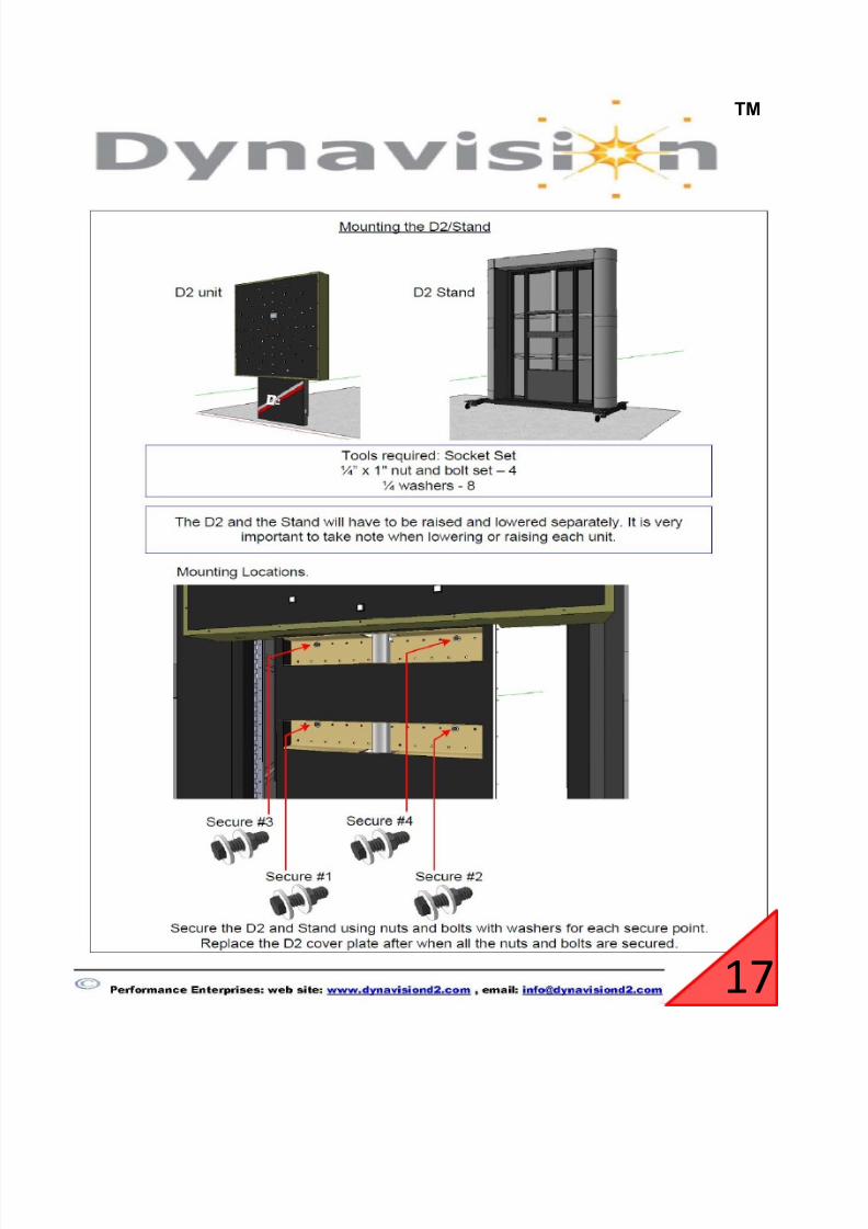
Machine Installation (Mounting the Machine to the stand) …… 17
Section #4 Dynavision D2 purchased without a Netbook
Flash Drive file unloading: ……………………………………………………… 24
SAFETY/MAINTENANCE INFORMATION ………….……………………………….. 26
3

7/29/2019 Installation Manual Rev. 12
http://slidepdf.com/reader/full/installation-manual-rev-12 4/26
TM
Section #1:
List of ContentsPART # DESCRIPTION QTY.
* Machine Dynavision D2 1
* Netbook Computer D2-6001 1
* 2 Pedestal Covers D2-2018 2
* AC Power Cord D2-3015 1
* Pedestal Cover Hardware D2-7041 8
* Wall Mount Hardware D2-7042 4
* Safety Strap HardwareD2-7036 1
D2-7035 1
* Shelf D2-2020 computer shelf (D2 with Netbook) 1
D2-2030 computer shelf 1
* Netbook Shelf Hardware D2-7033 2
D2-7034 #6x1-1/4" sheet metal screw 2
* Netbook Cable D2-4059 cable assembly 1
* VGA Cable D2-4084 VGA Cable 1
DynavisionTM recommends that you use two people in setting up the
D2. Before beginning the machine installation steps, take a moment
to inventory the contents of the crate. In it should be the following:
Netbook
cover
6-32x3/8 flat head screw
Wall Mounted Dynavision D2
1/4" oval threaded connector
plastic drywall anchor
10 ft. power Cord
or
1/4 x1-1/4" hex wash hd screw
#4 wood screw eyebolt
4

7/29/2019 Installation Manual Rev. 12
http://slidepdf.com/reader/full/installation-manual-rev-12 5/26
TM
1. Unpacking the machine* Remove all loose packed items; Netbook, covers, cables and hardware.
*
*
*
With your helper, lift the machine out of the box. Use the wheel assemblies as
handles to lift with.
Once removed from the crate, stand it up against the wall that the machine will
be fastened to.
Locate the power cord and insert it in the receptacle located on the left side of
the pedestal and plug it into the power outlet on your wall.
5

7/29/2019 Installation Manual Rev. 12
http://slidepdf.com/reader/full/installation-manual-rev-12 6/26
TM
*
*
2. Machine Installation (Mounting the Machine to the Wall)
*
*Measure from the floor up (along the stud in the wall) 61 inches and make a
mark on the wall.
Once the machine is raised to expose the mounting holes, unplug the power
cord from the wall and proceed to follow the instructions below in section 2.
Press the height adjustment button
(rocker switch) on the left side of the
Light Board. Raise the Light Board to
expose a series of mounting holes which
you will use to mark the correct position
to fasten the machine to the wall. The
mounting will be explained further
below.
Locate the stud in the wall near where you want the machine mounted. NOTE:This stud will not be on the centerline of where the pedestal is attached to the
wall. It will be approx. 3 inches to the left of center of where the pedestal will be
mounted.
6

7/29/2019 Installation Manual Rev. 12
http://slidepdf.com/reader/full/installation-manual-rev-12 7/26
TM
*
*
*
*
From the bag marked Pedestal Wall Mount Hardware Kit, screw the screw eye
into the stud until the base of the eye touches the wall. Slip the screw locking
carabineer into the eye.
Using a 3/16” drill bit, drill a pilot hole in the wall at the mark. Drill the holeapprox. one inch deep.
Lift the machine up towards the wall. Once close, have your helper hook the
carabineer into the safety/service strap. The machine will now hang in place.
Press the machine up against the wall. Using the pedestal hardware screws
shipped in the crate, fasten the pedestal to the wall screwing the 4 screws into
the studs in the wall. The picture below indicates where the mounting screws
should be spread out.
7

7/29/2019 Installation Manual Rev. 12
http://slidepdf.com/reader/full/installation-manual-rev-12 8/26
TM
* Secure the two pedestal covers from the shipping crate over the mounting openings with eight black #6 x 3/8” screws from the bag marked “ Cover Hardware"
Pedestal to be mounted to the wall though
holes located in pedestal.
8

7/29/2019 Installation Manual Rev. 12
http://slidepdf.com/reader/full/installation-manual-rev-12 9/26
TM
3. Installation of Netbook Tray
*
* Fasten the Netbook holder to the wall with the hardware provided in the
bag marked shelf hardware.
Mark the location of the 2 holes on the wall at a level that is comfortable to type
and also to see the monitor of the Netbook, typically between 48" to 54" high.
9

7/29/2019 Installation Manual Rev. 12
http://slidepdf.com/reader/full/installation-manual-rev-12 10/26
TM
* Once the D2 is mounted, connect the electrical power cord into the unit.Connect the Netbook or computer to the machine and follow the instructions
contained in the Operators Manual located on the Netbook computer. The
Netbook cable and VGA cable are connected to the machine on the left side of
the Light Board .The location to plug the cables can be found under the bottom
of the Light Board, a gentle insertion force should be used. Also make sure that
the cable with the latch is oriented in the correct direction, “DO NOT FORCE”
The cable should be able to be inserted with very little force.
Netbook Cable
VGA Cable
NOTE WELL: IF THE MACHINE IS FASTENED DIRECTLY TO DRYWALL, IT IS VERY
IMPORTANT THAT THE MACHINE IS INSPECTED EVERY 3 MONTHS TO MAKE SURE THAT
NONE OF THE PLUGS IN THE DRYWALL HAVE COME LOOSE AFTER CONTINUOUS USE. IT
IS PREFERRED ( NOT MANDATORY) THAT THE MACHINE IS FASTENED TO A WOODEN
BACKING, SO THAT THERE IS PROPER ENGAGEMENT OF THE MOUNTING SCREWS SO
THAT THEY CANNOT COME LOOSE AFTER CONTINUOUS OPERATION OF THE MACHINE.
PLEASE NOTE ALSO THAT THE SAFETY STRAP MUST BE ATTACHED TO A WALL STUD.
10

7/29/2019 Installation Manual Rev. 12
http://slidepdf.com/reader/full/installation-manual-rev-12 11/26
TM
Section #2:
List of ContentsPART # DESCRIPTION QTY.
* Machine Dynavision D2 1
* Netbook Computer D2-6001 1
* AC Power Cord D2-3015 10 ft. power Cord 1
* Wall Mount Hardware D2-7042 1/4 x1-1/4" hex wash hd screw 4
* Safety Strap Hardware D2-7036 #4 wood screw eyebolt 1
D2-7035 1
* Shelf D2-2020 computer shelf (D2 with Netbook) 1
D2-2030 computer shelf 1
* Netbook Shelf Hardware D2-7033 plastic drywall anchor 2
D2-7034 #6x1-1/4" sheet metal screw 2
* Netbook Cable D2-4059 cable assembly 1
* Basic Stand D2-6017 Stand 1
* VGA Cable D2-4084 VGA Cable 1
or
Basic Stand Mounted Dynavision D2
DynavisionTM recommends that you use two people in setting up the
D2. Before beginning the machine installation steps, take a moment
to inventory the contents of the crate and skid. In it should be the
following:
Netbook
1/4" oval threaded connector
11

7/29/2019 Installation Manual Rev. 12
http://slidepdf.com/reader/full/installation-manual-rev-12 12/26
TM
1. Unpacking the Machine
* Remove all loose packed items; Netbook, covers, cables and hardware.
*
*
*
*
Once removed from the crate, center it in the stand.
After leaning the Dynavision D2 against the stand attach the safety strap to the
stand as shown below. Use the oval connector provided with the D2 in the crate.
This will prevent the D2 from falling while you bolt the D2 to the stand.
Remove the stand from the crate, remove all protective packaging and assemble
the base, computer tray and upright with bolts provided. Lock the four casters.
With your helper, lift the machine out of the box. Use the wheel assemblies as
handles to lift with.
12
7/29/2019 Installation Manual Rev. 12
http://slidepdf.com/reader/full/installation-manual-rev-12 13/26
TM
*
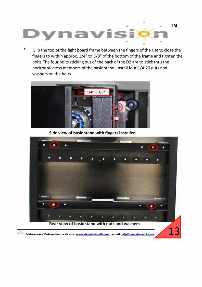
Side view of basic stand with fingers installed.
Rear view of basic stand with nuts and washers
Slip the top of the light board frame between the fingers of the risers; close thefingers to within approx. 1/4" to 3/8" of the bottom of the frame and tighten the
bolts.The four bolts sticking out of the back of the D2 are to stick thru the
horizontal cross members of the basic stand. Install four 1/4-20 nuts and
washers on the bolts.
13
1/4" to 3/8"

7/29/2019 Installation Manual Rev. 12
http://slidepdf.com/reader/full/installation-manual-rev-12 14/26
TM
3. Insta ation o Net oo on t e Tray
* Position the Netbook in the Netbook tray by adjusting the two side guides and
tightening the thumb nuts on the bottom of the tray.
14

7/29/2019 Installation Manual Rev. 12
http://slidepdf.com/reader/full/installation-manual-rev-12 15/26
TM
* Once the Light board is mounted, connect the electrical power cord into the
unit. Connect the Netbook or computer to the machine and follow the
instructions contained in the Operators Manual located on the Netbook
computer. The Netbook cable and VGA cable are connected to the machine on
the left side of the Light Board .The location to plug the cables can be found
under the bottom of the Light Board, a gentle insertion force should be used.
Also make sure that the cable with the latch is oriented in the correct direction,
“DO NOT FORCE” The cable should be able to be inserted with very little force.
Netbook Cable
VGA Cable
15

7/29/2019 Installation Manual Rev. 12
http://slidepdf.com/reader/full/installation-manual-rev-12 16/26
TM
Section #3:
List of ContentsPART # DESCRIPTION QTY.
* Machine Dynavision D2 1
* Netbook Computer D2-6001 1
* 2 Pedestal Covers D2-2018 2
* AC Power Cord D2-3015 1
* Pedestal Cover Hardware D2-7041 8
* Wall Mount Hardware D2-7042 4
* Safety Strap Hardware D2-7036 1
D2-7035 1
* Shelf D2-2020 computer shelf (D2 with Netbook) 1
D2-2030 computer shelf 1
* Netbook Shelf Hardware D2-7033 2
D2-7034 #6x1-1/4" sheet metal screw 2
* Netbook Cable D2-4059 cable assembly 1
* Deluxe Stand D2-6018 stand 1
* VGA Cable D2-4084 VGA Cable 1
cover
Deluxe Stand Mounted Dynavision D2
10 ft. power Cord
#4 wood screw eyebolt
1/4" oval threaded connector
plastic drywall anchor
1/4 x1-1/4" hex wash hd screw
or
DynavisionTM recommends that you use two people in setting up the
D2. Before beginning the machine installation steps, take a moment
to inventory the contents of the crate and skid. In it should be the
following:
Netbook
6-32x3/8 flat head screw
16
7/29/2019 Installation Manual Rev. 12
http://slidepdf.com/reader/full/installation-manual-rev-12 17/26
TM
17
7/29/2019 Installation Manual Rev. 12
http://slidepdf.com/reader/full/installation-manual-rev-12 18/26
TM
18

7/29/2019 Installation Manual Rev. 12
http://slidepdf.com/reader/full/installation-manual-rev-12 19/26
TM
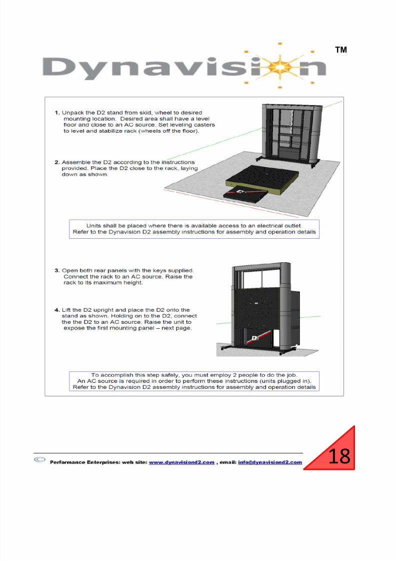
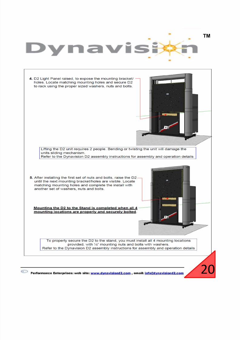
Prior to bolting the Dynavision D2 to the Deluxe stand attach the safety strap as shown
in the picture below. Use the oval connector provided with the D2 in the crate. This will
prevent the D2 from falling while you bolt the D2 to the stand.
19
7/29/2019 Installation Manual Rev. 12
http://slidepdf.com/reader/full/installation-manual-rev-12 20/26
TM
20

7/29/2019 Installation Manual Rev. 12
http://slidepdf.com/reader/full/installation-manual-rev-12 21/26
TM
Insta ation o Net oo on t e Tray
*
* Position the Netbook in the Netbook tray by adjusting the two side guides and
tightening the thumb nuts on the bottom of the tray.
Attach the Netbook Holder to the rear of the Deluxe stand with two 1/4-20 bolts. After holding the Netbook holder in the location you like; tighten the bolts at theknuckle joints to hold it in place.
21

7/29/2019 Installation Manual Rev. 12
http://slidepdf.com/reader/full/installation-manual-rev-12 22/26
TM
*
* Once the Light board is mounted, connect the electrical power cord into theunit. Connect the Netbook or computer to the machine and follow the
instructions contained in the Operators Manual located on the Netbook
computer. The Netbook cable and VGA cable are connected to the machine on
the left side of the Light Board .The location to plug the cables can be found
under the bottom of the Light Board, a gentle insertion force should be used.
Also make sure that the cable with the latch is oriented in the correct direction,
“DO NOT FORCE” The cable should be able to be inserted with very little force.
Secure the two pedestal covers from the shipping crate over the mounting openings with eight black #6 x 3/8” screws from the bag marked “ Cover Hardware"
22

7/29/2019 Installation Manual Rev. 12
http://slidepdf.com/reader/full/installation-manual-rev-12 23/26
TM
Netbook Cable
VGA Cable
23
7/29/2019 Installation Manual Rev. 12
http://slidepdf.com/reader/full/installation-manual-rev-12 24/26
TM
Section #4:
STARTUP PROCEDURE
1. Insert Flash Drive into the USB port of Computer/Net Book.
2.
3.
4.
5.
D2 without a Netbook
If your D2 was purchased without a Netbook; set up your D2 using section 1, 2 or 3 of
this installation manual. Use the following procedure to load all files from the flash drive
onto your Netbook or computer. The flash drive is supplied in the crate with the D2.
Click on the “Start” menu and open a second “Computer” Window. Then
Click into the “C:\” Drive.
Drag the “Dynavision” Folder off the Flash Drive into the “C:\” Drive folder.
Next drag the “noisivand.dih” Folder into the “Windows” Folder located onthe “C:\” Drive.
Wait for the “Auto Play” window to open up, and then double click on
“Open Folders”. **Note: If “Auto Play” Window does not come up go down
to the “Start” menu and open up “Computer” Window. Once the
“Computer” window is open look for the Flash Drive or Drive titled“Dynavision”
24
7/29/2019 Installation Manual Rev. 12
http://slidepdf.com/reader/full/installation-manual-rev-12 25/26
TM
6.
7.
8.
9.
Repeat step 0.6 for the Installation Manual, Trouble Shooting Manual,
and Operators Manual.
Drag the “PL2303” File onto the desktop and install the driver by double
clicking on the icon.
Side Note: This is an optional step, if you do not want MacAfee Anti-Virus
you may un-install it and install Microsoft Security Essentials on to the
computer by double clicking on the “mseinstall.exe”
Go into the “Dynavision” Folder and Right click on the “Dynavision.exe”
file scroll cursor down to “send to” then click on “Desktop (create
shortcut). This will setup a shortcut onto your desktop.
25

7/29/2019 Installation Manual Rev. 12
http://slidepdf.com/reader/full/installation-manual-rev-12 26/26
TM
26