installation, operating and service instructions clw
TRANSCRIPT
1
INSTALLATION, OPERATINGAND SERVICE INSTRUCTIONS
"CLW" SERIESCAST IRON OIL-FIRED BOILER
nonoitamrofnignikeesnehW.rotcartnocgnitaehruoyllac,reliobotsriaperroecivresroF.lebaLgnitaRnonwohssarebmuNlaireSdnarebmuNledoMrelioBedivorp,reliob
rebmuNledoMrelioB rebmuNlaireSrelioB etaDnoitallatsnI
___-_-WLC _______6rotcartnoCgnitaeH rebmuNenohP
sserddA
2
IMPORTANT INFORMATION - PLEASE READ THIS PAGE CAREFULLY1. THIS BOILER HAS LIMITED WARRANTIES, COPIES OF WHICH ARE PRINTED ON THE BACK COVER OF THIS
MANUAL.2. THIS BOILER IS SUITABLE FOR INSTALLATION ON COMBUSTIBLE FLOORING. BOILER CANNOT BE IN-
STALLED ON CARPETING.3. ALL BOILERS MUST BE INSTALLED IN ACCORDANCE WITH NATIONAL, STATE AND LOCAL PLUMBING,
HEATING AND ELECTRICAL CODES AND THE REGULATIONS OF THE SERVING UTILITIES WHICH MAYDIFFER FROM THIS MANUAL. AUTHORITIES HAVING JURISDICTION SHOULD BE CONSULTED BEFOREINSTALLATIONS ARE MADE.IN ALL CASES, REFERENCE SHOULD BE MADE TO THE FOLLOWING STANDARDS:
A. Current Edition of American National Standard ANSI/NFPA 31, “Installation of Oil Burning Equipment”, for clearances between boiler, ventconnector and combustible material.
B. Current Edition of American National Standard ANSI/NFPA 211, “Chimneys, Fireplaces, Vents, and Solid Fuel Burning Appliances”, For Chimneyrequire-ments, type of venting material and clearances between vent connector pipe and combustible materials.
C. Current Edition of American Society of Mechanical Engineers ASME CSD-1, “Controls and Safety Devices for Automatically Fired Boilers”, forassembly and operations of controls and safety devices.
4. ALL HEATING SYSTEMS SHOULD BE DESIGNED BY COMPETENT CONTRACTORS AND ONLY PERSONSKNOWLEDGEABLE IN THE LAYOUT AND INSTALLATION OF HYDRONIC HEATING SYSTEMS SHOULDATTEMPT INSTALLATION OF ANY BOILER.
5. THE BOILER MUST BE CONNECTED TO AN APPROVED CHIMNEY IN GOOD CONDITION. SERIOUS PROPERTYDAMAGE COULD RESULT IF THE BOILER IS CONNECTED TO A DIRTY OR INADEQUATE CHIMNEY. THEINTERIOR OF THE CHIMNEY FLUE MUST BE INSPECTED AND CLEANED BEFORE THE START OF THE HEAT-ING SEASON AND SHOULD BE INSPECTED PERIODICALLY THROUGHOUT THE HEATING SEASON FOR ANYOBSTRUCTIONS. A CLEAN AND UNOBSTRUCTED CHIMNEY FLUE IS NECESSARY TO ALLOW NOXIOUSFUMES THAT COULD CAUSE INJURY OR LOSS OF LIFE TO VENT SAFELY AND WILL CONTRIBUTE TOWARDMAINTAINING THE BOILER’S EFFICIENCY.
6. READ THE LITERATURE ENCLOSED BY THE MANUFACTURER WITH THE VARIOUS ACCESSORY DEVICES.THESE ACCESSORY DEVICES MUST BE INSTALLED AND USED ACCORDING TO THE RECOMMENDATIONSOF THE MANUFACTURER.
7. IT IS THE RESPONSIBILITY OF THE INSTALLING CONTRACTOR TO SEE THAT ALL CONTROLS ARE COR-RECTLY INSTALLED AND ARE OPERATING PROPERLY WHEN THE INSTALLATION IS COMPLETED.
8. FOR OPTIMUM PERFORMANCE AND SERVICEABILITY FROM THIS BOILER ADHERE TO THE FOLLOWINGRECOMMENDATIONS:
A. DO NOT TAMPER WITH THE BOILER OR CONTROLS. Retain your contractor or a competent serviceman to assure that the boiler isproperly adjusted and maintained.
B. Have flueways cleaned at least once a year - preferably at the end of the heating season to remove soot and scale. Inside of firebox should also becleaned at the same time.
C. Have oil burner and controls checked at least once a year or as may be necessitated.
GNINRAWESACKNARC,ENILOSAGESUTONOD.YLNOLIOLEUF2.ONNRUBOTDENGISEDSIRELIOBSIHT
.RELIOBSIHTNIREPAPROEGABRAGNRUBREVEN.ENILOSAGGNINIATNOCLIOYNARO,SGNINIARD,SAGLARUTAN.E.I(LEUFSUOESAGRO)LAOC,DOOW.E.I(LEUFDILOSYNAOTTREVNOCTONOD
TPEKEBDLUOHS,.CTE,SPARCSDOOW,REPAP,SGAR,SIRBEDELBAMMALFLLA.)ENAPORP/PL.SDRAZAHERIFFOEERFDNANAELCAERARELIOBEHTPEEK.SEMITLLATARELIOBEHTFORAELC
ytreporperevesesuacnachcihwdrazahlaitnetopaevahroodgniwsrenrubhtiwdeppiuqesreliobllAothctiwsecivresffonrut,roodgniwsgninepoerofeB.derongifiefilfossolroyrujnilanosrep,egamadlatnediccatneverpotssenrahgniriwkcolretnIrooDgniwSrenruBfosevlahowttcennocsiddnareliob
htedistuorenrubfognirif yletelpmocrenetsafroodgniwsnethgitoteruseB.rebmahcnoitsubmoce.detelpmocsiecivresnehwkcolretnIrooDgniwSrenruBfosevlahowttcennocerdna
GNINRAWcitamotuanallatsnI.yrujnignidlacsrosnrubfoksirehtesaercniserutarepmetretawhgiHehttaretawtohylevissecxediovaotteltuoretaehsselknatehttaevlav)gnixim(gnirepmet
.serutxif
3
TABLE OF CONTENTSI. General Information .............................. 3
II. Installation Instructions ......................... 6III. Operating and Service Instructions ..... 13
IV. Boiler Cleaning ................................... 19V. Repair Parts ......................................... 20
Burner Specifications .......................... 14
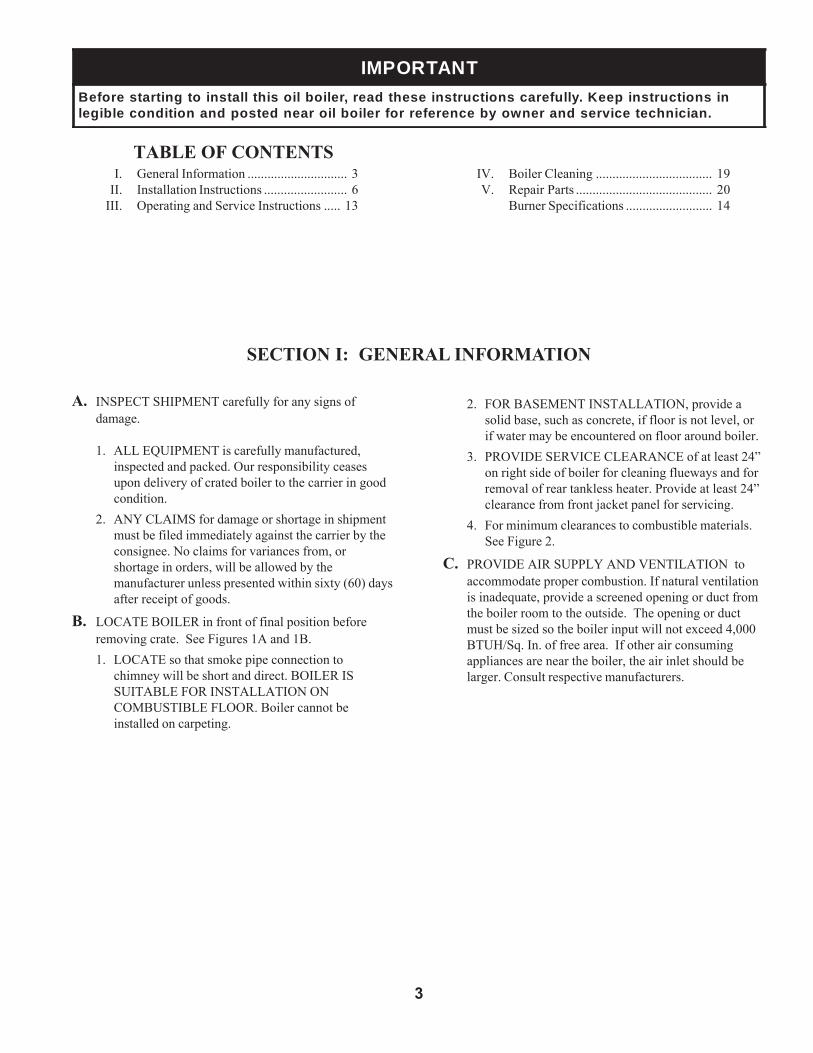
SECTION I: GENERAL INFORMATION
TNATROPMInisnoitcurtsnipeeK.ylluferacsnoitcurtsniesehtdaer,reliobliosihtllatsniotgnitratserofeB
.naicinhcetecivresdnarenwoybecnereferrofrelioblioraendetsopdnanoitidnocelbigel
A. INSPECT SHIPMENT carefully for any signs ofdamage.
1. ALL EQUIPMENT is carefully manufactured,inspected and packed. Our responsibility ceasesupon delivery of crated boiler to the carrier in goodcondition.
2. ANY CLAIMS for damage or shortage in shipmentmust be filed immediately against the carrier by theconsignee. No claims for variances from, orshortage in orders, will be allowed by themanufacturer unless presented within sixty (60) daysafter receipt of goods.
B. LOCATE BOILER in front of final position beforeremoving crate. See Figures 1A and 1B.1. LOCATE so that smoke pipe connection to
chimney will be short and direct. BOILER ISSUITABLE FOR INSTALLATION ONCOMBUSTIBLE FLOOR. Boiler cannot beinstalled on carpeting.
2. FOR BASEMENT INSTALLATION, provide asolid base, such as concrete, if floor is not level, orif water may be encountered on floor around boiler.
3. PROVIDE SERVICE CLEARANCE of at least 24”on right side of boiler for cleaning flueways and forremoval of rear tankless heater. Provide at least 24”clearance from front jacket panel for servicing.
4. For minimum clearances to combustible materials.See Figure 2.
C. PROVIDE AIR SUPPLY AND VENTILATION toaccommodate proper combustion. If natural ventilationis inadequate, provide a screened opening or duct fromthe boiler room to the outside. The opening or ductmust be sized so the boiler input will not exceed 4,000BTUH/Sq. In. of free area. If other air consumingappliances are near the boiler, the air inlet should belarger. Consult respective manufacturers.
4
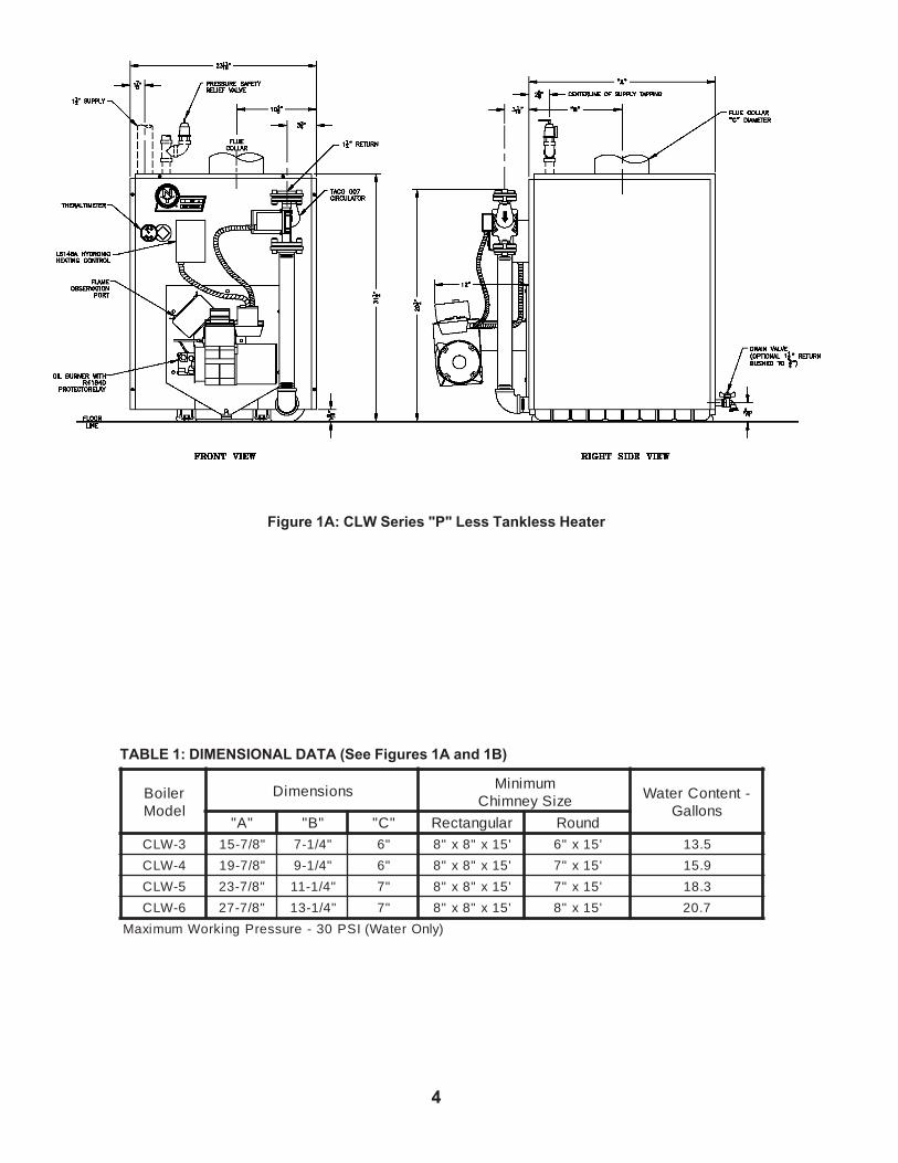
Figure 1A: CLW Series "P" Less Tankless Heater
relioBledoM
snoisnemiD muminiMeziSyenmihC -tnetnoCretaW
snollaG"A" "B" "C" ralugnatceR dnuoR
3-WLC "8/7-51 "4/1-7 "6 '51x"8x"8 '51x"6 5.31
4-WLC "8/7-91 "4/1-9 "6 '51x"8x"8 '51x"7 9.51
5-WLC "8/7-32 "4/1-11 "7 '51x"8x"8 '51x"7 3.81
6-WLC "8/7-72 "4/1-31 "7 '51x"8x"8 '51x"8 7.02
)ylnOretaW(ISP03-erusserPgnikroWmumixaM
TABLE 1: DIMENSIONAL DATA (See Figures 1A and 1B)

5
Figure 1B: CLW Series "PT" With Tankless Heater
AevobA
BtnorF
CyenmihCrotcennoC
DraeR
EsediS
6 42 81 6 6
Figure 2: Minimum Installation Clearances To Combustible Materials (Inches)
htiwylpmocsecnaraelcdetsiL:1ETONdradnatS,13APFNdradnatSlanoitaNnaciremA
.tnempiuqEgninruBliOfonoitallatsnIehtrof
nidellatsniebnacsreliobseireSWLC:2ETONelbitsubmocmorfsecnaraelchtiwsmoor
secnaraelcdetsiL.evobadetsilsalairetamtesolcroevoclarofdecuderebtonnac
.snoitallatsni
elbitsubmocotsecnaraelcdecuderroF:3ETONsadedivorpebtsumnoitcetorp,lairetam
.dradnats13APFN/ISNAevobaehtnidebircsed

6
SECTION II: INSTALLATION INSTRUCTIONSA. REMOVE CRATE
1. Remove all fasteners at crate skid.2. Lift outside container and remove all other inside
protective spacers and bracing. Removemiscellaneous trim carton containing relief valve,circulator and fittings, drain valve and pipe fittings.
section, see Figures 1A or 1B.d. Use a boiler water bypass if the boiler is to be
operated in a system which has a large volume orexcessive radiation where low boiler watertemperature may be encountered (i.e. convertedgravity circulation system, etc.).Install a pipe tee between the circulator andboiler return along with a second tee in thesupply piping as shown in Figure 4. The bypassshould be the same size as the supply and returnlines. Locate valves in the bypass and supplyoutlet as illustrated in Figure 4 for regulation ofwater flow to maintain higher boiler watertemperature.Set the by-pass and boiler supply valves to a halfthrottle position to start. Operate boiler until thesystem water temperature is a normal operatingrange.Adjust the valves to provide 180° to 200°Fsupply water temperature. Opening the boilersupply valves will raise the system temperature,while opening the bypass valve will lower thesystem supply temperature.
e. If this boiler is connected to heating coils locatedin air handling units where they may be exposedto refrigerated air the boiler piping must beequipped with flow control valves to preventgravity circulation of boiler water during theoperation of the cooling system.
f. If this boiler is used in connection with
B. REMOVAL OF BOILER FROM SKID
1. Boiler is secured to base with 4 carriage bolts, 2 onleft side and 2 on right side. See Figure 3. Removeall bolts.
2. Tilt boiler to right and to rear. Using right rear leg aspivot, rotate boiler 90° in a clockwise direction, andlower left side of boiler to floor. Tilt boiler andremove crate skid. Care should be exercised toprevent damage to jacket or burner.
C. MOVE BOILER TO PERMANENT POSITION bysliding or walking.
D. INSPECT COMBUSTION TARGET WALL ANDCOMBUSTION CHAMBER LINER1. OPEN FLAME OBSERVATION DOOR AND/OR
BURNER SWING DOOR on front of boiler. Useflashlight to inspect target wall secured to rearsection with silastic sealant. Inspect ceramic fiberblanket secured to floor of boiler with water glassadhesive. If either is damaged they must be replaced.
E. CONNECT SUPPLY AND RETURN PIPING TOHEATING SYSTEM.1. CLEARANCES — Hot water pipes shall have
clearances of at least ½” from all combustibleconstruction.a. For Forced Circulation HOT WATER
HEATING. See Figure 4. Consult I=B=RInstallation and Piping Guide No. 200.
b. Screw drain valve into 1½" tapping in rearsection using 1½" x ¾" bushing.
c. Install relief valve and fittings in top of front
Figure 3: Removal of Boiler From Skid Figure 4: Recommended Boiler Piping For SeriesLoop Hot Water System

7
Figure 5: Recommended Piping for CombinationHeating & Cooling (Refrigeration) Systems Water
Boilersrefrigeration systems, the boiler must be installedso that the chilled medium is piped in parallelwith the heating boiler using appropriate valvesto prevent the chilled medium from entering theboiler, see Figure 5. Also consult I=B=RInstallation and Piping Guides.
g. A hot water boiler installed above radiation levelmust be provided with a low water cutoff deviceas part of the installation.
NOITUACretawreliobehtfonoitanimatnocnegyxO
reliobleetsdnanorifonoisorrocesuaclliw.eruliafreliobotdaelnacdna,stnenopmoc
tonseodytnarrawdradnatss'rekroYweNnegyxoybdesuacsmelborprevoc
.retawreliobfonoitanimatnoc
There are many possible causes of oxygen contaminationsuch as:
a. Addition of excessive make-up water as a resultof system leaks.
b. Absorption through open tanks and fittings.c. Oxygen permeable materials in the distribution
system.In order to insure long product life, oxygen sources
should be eliminated. This can be accomplished by takingthe following measures:
a. Repairing system leaks to eliminate the need foraddition of make-up water.
b. Eliminating open tanks from the system.c. Eliminating and/or repairing fittings which allow
oxygen absorption.d. Use of non-permeable materials in the
distribution system.e. Isolating the boiler from the system water by
Figure 6: Schematic Tankless Heater Piping
installing a heat exchanger.
F. CONNECT TANKLESS HEATER PIPING ASSHOWN IN Figure 6. See Table 2 for Tankless Heater
TABLE 2: TANKLESS HEATER DATA
ledoMrelioB )MPG(gnitaRporDerusserP
)ISP(
3-WLC 3 7.4
4-WLC ¼3 6.5
5-WLC ½3 4.6
6-WLC ¾3 2.7
Ratings.THE FOLLOWING GUIDELINES SHOULD BE FOL-LOWED WHEN PIPING THE TANKLESS HEATER:
1. FLOW REGULATION — If flow through theheater is greater than its rating, the supply ofadequate hot water may not be able to keep up withthe demand. For this reason a flow regulatormatching the heater rating should be installed in thecold water line to the heater. The flow regulatorshould preferably be located below the inlet to theheater and a minimum of 3’ away from the inlet sothat the regulator is not subjected to excesstemperatures that may occur during “off” periodswhen it is possible for heat to be conducted backthrough the supply line. The flow regulator alsolimits the flow of supply water regardless of inletpressure variations in the range of 20 to 125 psi.
2. TEMPERING OF HOT WATER — Installation ofan automatic mixing valve will lengthen the deliveryof the available hot water by mixing some cold waterwith the hot. This prevents excessive and possiblyscalding hot water at the fixtures. In addition,savings of hot water will be achieved since the userwill not waste as much hot water while seekingwater temperature to his liking. Higher temperaturehot water required by dishwashers and automaticwashers is possible by piping the hot water from the
8
heater prior to entering the mixing valve. The mixingvalve should be “trapped” by installing it below thecold water inlet to heater to prevent lime formationin the valve.
GNINRAWsselknattaevlavgniximcitamotuallatsnI
rosnrubfoksirdiovaotteltuoretaehtaretawtohylevissecxeoteudgnidlacsgniximehtniatniamdnatsujdA.serutxif
s'rerutcafunamehthtiwecnadroccanievlav.snoitcurtsni
3. FLUSHING OF HEATER — All water containssome sediment which settles on the inside of thecoil. Consequently, the heater should be periodicallybackwashed. This is accomplished by installing hosebibs as illustrated and allowing water at city pressureto run into hose bib A, through the heater, and outhose bib B until the discharge is clear. The tees inwhich the hose bibs are located should be the samesize as heater connections to minimize pressuredrop.
4. HARD WATER — A water analysis is necessary todetermine the hardness of your potable water. This isapplicable to some city water and particularly towell water. An appropriate water softener should beinstalled based on the analysis and dealer’srecommendation. This is not only beneficial to thetankless heater but to piping and fixtures plus themany other benefits derived from soft water.
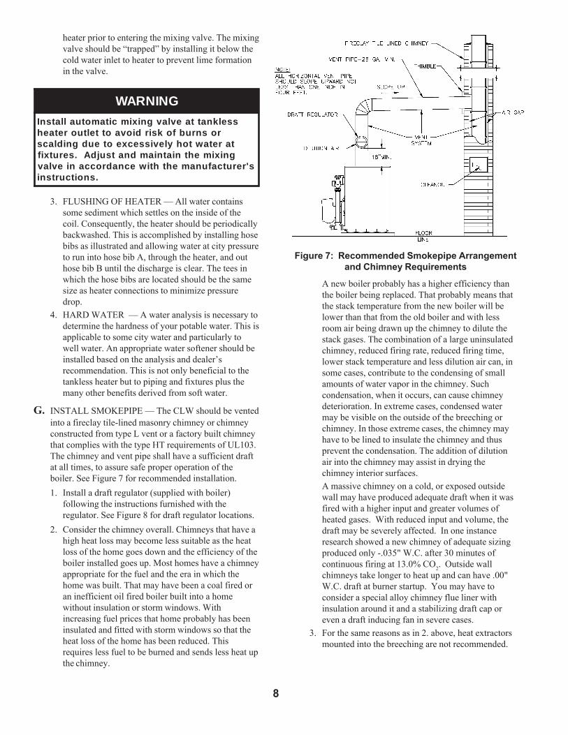
G. INSTALL SMOKEPIPE — The CLW should be ventedinto a fireclay tile-lined masonry chimney or chimneyconstructed from type L vent or a factory built chimneythat complies with the type HT requirements of UL103.The chimney and vent pipe shall have a sufficient draftat all times, to assure safe proper operation of theboiler. See Figure 7 for recommended installation.1. Install a draft regulator (supplied with boiler)
following the instructions furnished with theregulator. See Figure 8 for draft regulator locations.
2. Consider the chimney overall. Chimneys that have ahigh heat loss may become less suitable as the heatloss of the home goes down and the efficiency of theboiler installed goes up. Most homes have a chimneyappropriate for the fuel and the era in which thehome was built. That may have been a coal fired oran inefficient oil fired boiler built into a homewithout insulation or storm windows. Withincreasing fuel prices that home probably has beeninsulated and fitted with storm windows so that theheat loss of the home has been reduced. Thisrequires less fuel to be burned and sends less heat upthe chimney.
Figure 7: Recommended Smokepipe Arrangementand Chimney Requirements
A new boiler probably has a higher efficiency thanthe boiler being replaced. That probably means thatthe stack temperature from the new boiler will belower than that from the old boiler and with lessroom air being drawn up the chimney to dilute thestack gases. The combination of a large uninsulatedchimney, reduced firing rate, reduced firing time,lower stack temperature and less dilution air can, insome cases, contribute to the condensing of smallamounts of water vapor in the chimney. Suchcondensation, when it occurs, can cause chimneydeterioration. In extreme cases, condensed watermay be visible on the outside of the breeching orchimney. In those extreme cases, the chimney mayhave to be lined to insulate the chimney and thusprevent the condensation. The addition of dilutionair into the chimney may assist in drying thechimney interior surfaces.A massive chimney on a cold, or exposed outsidewall may have produced adequate draft when it wasfired with a higher input and greater volumes ofheated gases. With reduced input and volume, thedraft may be severely affected. In one instanceresearch showed a new chimney of adequate sizingproduced only -.035" W.C. after 30 minutes ofcontinuous firing at 13.0% CO2. Outside wallchimneys take longer to heat up and can have .00"W.C. draft at burner startup. You may have toconsider a special alloy chimney flue liner withinsulation around it and a stabilizing draft cap oreven a draft inducing fan in severe cases.
3. For the same reasons as in 2. above, heat extractorsmounted into the breeching are not recommended.
9
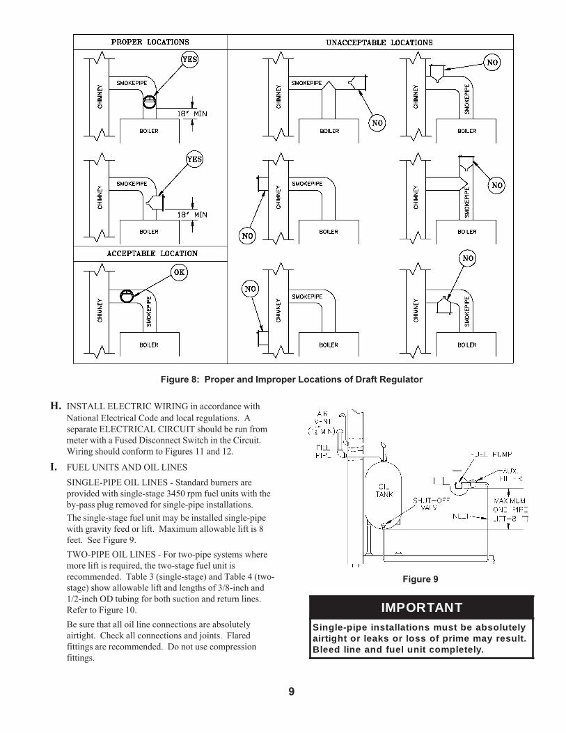
Figure 8: Proper and Improper Locations of Draft Regulator
H. INSTALL ELECTRIC WIRING in accordance withNational Electrical Code and local regulations. Aseparate ELECTRICAL CIRCUIT should be run frommeter with a Fused Disconnect Switch in the Circuit.Wiring should conform to Figures 11 and 12.
I. FUEL UNITS AND OIL LINESSINGLE-PIPE OIL LINES - Standard burners areprovided with single-stage 3450 rpm fuel units with theby-pass plug removed for single-pipe installations.The single-stage fuel unit may be installed single-pipewith gravity feed or lift. Maximum allowable lift is 8feet. See Figure 9.TWO-PIPE OIL LINES - For two-pipe systems wheremore lift is required, the two-stage fuel unit isrecommended. Table 3 (single-stage) and Table 4 (two-stage) show allowable lift and lengths of 3/8-inch and1/2-inch OD tubing for both suction and return lines.Refer to Figure 10.Be sure that all oil line connections are absolutelyairtight. Check all connections and joints. Flaredfittings are recommended. Do not use compressionfittings.
Figure 9
TNATROPMIyletulosbaebtsumsnoitallatsniepip-elgniS.tluseryamemirpfossolroskaelrothgitria
.yletelpmoctinuleufdnaenildeelB
10
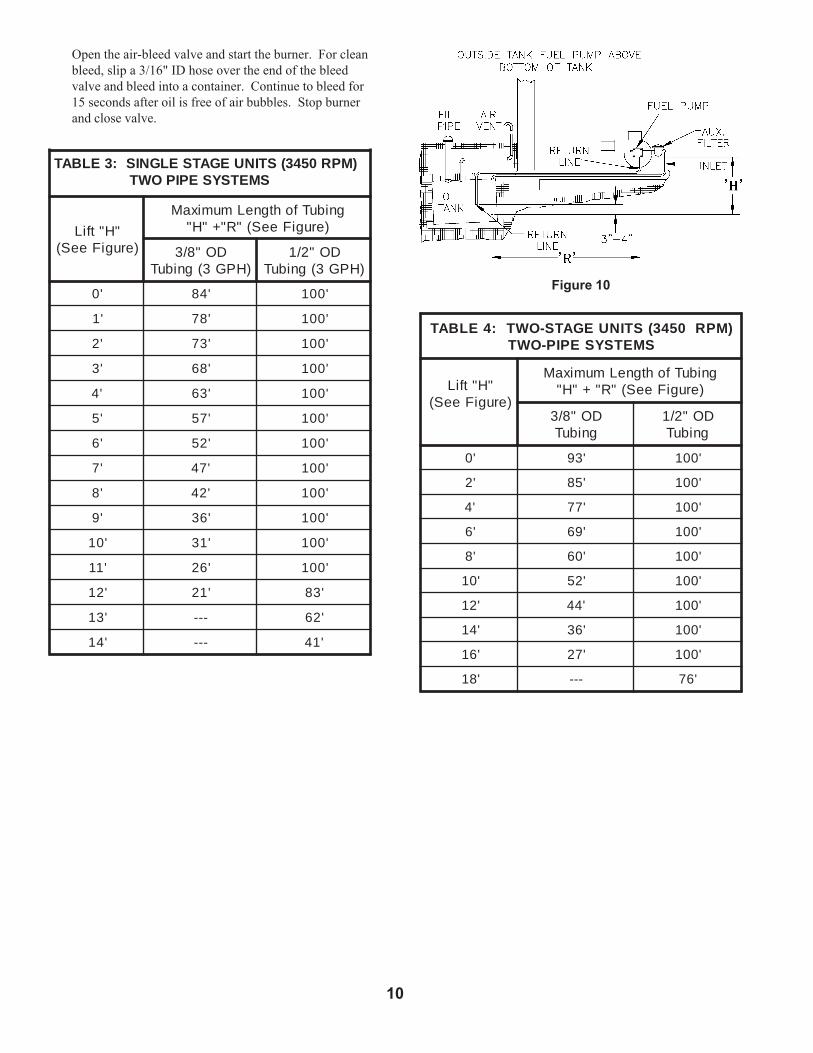
Open the air-bleed valve and start the burner. For cleanbleed, slip a 3/16" ID hose over the end of the bleedvalve and bleed into a container. Continue to bleed for15 seconds after oil is free of air bubbles. Stop burnerand close valve.
)MPR0543(STINUEGATSELGNIS:3ELBATSMETSYSEPIPOWT
"H"tfiL)erugiFeeS(
gnibuTfohtgneLmumixaM)erugiFeeS("R"+"H"
DO"8/3)HPG3(gnibuT
DO"2/1)HPG3(gnibuT
'0 '48 '001
'1 '87 '001
'2 '37 '001
'3 '86 '001
'4 '36 '001
'5 '75 '001
'6 '25 '001
'7 '74 '001
'8 '24 '001
'9 '63 '001
'01 '13 '001
'11 '62 '001
'21 '12 '38
'31 --- '26
'41 --- '14
Figure 10
)MPR0543(STINUEGATS-OWT:4ELBATSMETSYSEPIP-OWT
"H"tfiL)erugiFeeS(
gnibuTfohtgneLmumixaM)erugiFeeS("R"+"H"
DO"8/3gnibuT
DO"2/1gnibuT
'0 '39 '001
'2 '58 '001
'4 '77 '001
'6 '96 '001
'8 '06 '001
'01 '25 '001
'21 '44 '001
'41 '63 '001
'61 '72 '001
'81 --- '67

11
Figure 11: Wiring Diagram for Water Boilers With Beckett AFG Burner andSplit Controls Less Tankless Heater
SEQUENCE OF OPERATIONA call for heat by the thermostat energizes the L8148A control which in turn energizes the R7184A primary control to turn on theburner. If burner ignites within approximately 45 seconds and cad cell see flame, the burner will continue to operate until the callfor heat is satisfied or the setting of the high limit is reached. The circulator will operate as long as the thermostat is calling forheat. If the thermostat is not satisfied and the high limit is reached, the circulator will continue to operate, and the burner will stopuntil the high limit is closed by a drop in boiler water temperature.
12
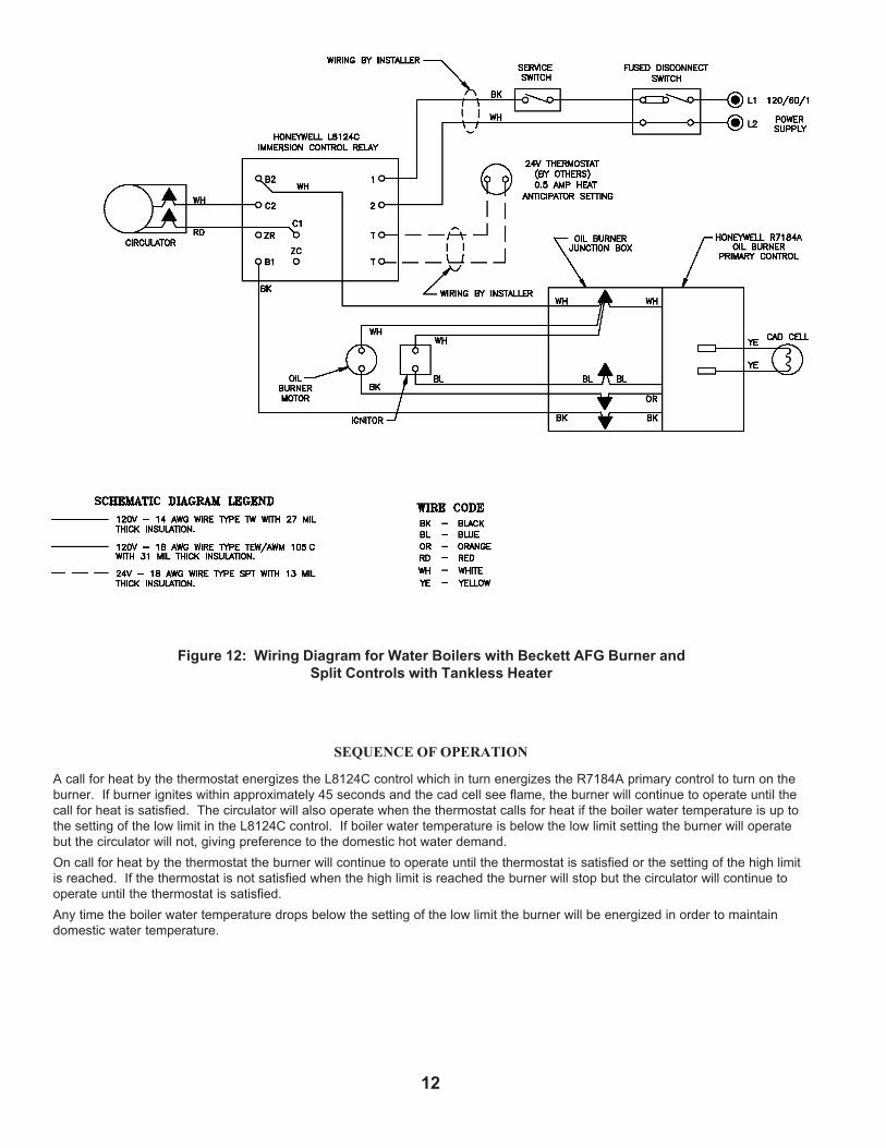
Figure 12: Wiring Diagram for Water Boilers with Beckett AFG Burner andSplit Controls with Tankless Heater
SEQUENCE OF OPERATION
A call for heat by the thermostat energizes the L8124C control which in turn energizes the R7184A primary control to turn on theburner. If burner ignites within approximately 45 seconds and the cad cell see flame, the burner will continue to operate until thecall for heat is satisfied. The circulator will also operate when the thermostat calls for heat if the boiler water temperature is up tothe setting of the low limit in the L8124C control. If boiler water temperature is below the low limit setting the burner will operatebut the circulator will not, giving preference to the domestic hot water demand.On call for heat by the thermostat the burner will continue to operate until the thermostat is satisfied or the setting of the high limitis reached. If the thermostat is not satisfied when the high limit is reached the burner will stop but the circulator will continue tooperate until the thermostat is satisfied.Any time the boiler water temperature drops below the setting of the low limit the burner will be energized in order to maintaindomestic water temperature.

13
SECTION III: OPERATING AND SERVICE INSTRUCTIONS
3. ON UNITS WITHOUT TANKLESS HEATERS,set high limit dial on L8148 at 210°F. Thistemperature may be varied to suit requirements ofinstallation.
4. ON UNITS WITH TANKLESS HEATERS, setoperating control dial on L8124 at 190°F and highlimit dial at 210°F. Operating Control must be aminimum of 20° below High Limit Setting. SetDifferential at 25°.
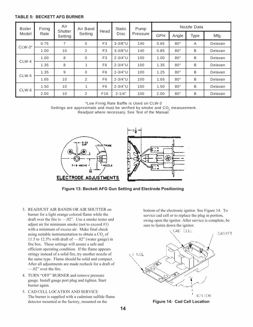
F. REMOVE GUN ASSEMBLY
1. CLW boilers are equipped with Beckett AFGburners. Items to be checked are nozzle size, headsize, gun setting, and positioning of electrodes. Thisinformation is shown in Figure 13 and Table 5.
2. Reinstall gun assembly.
G. ADJUST OIL BURNER BEFORE STARTING.
1. SET BURNER AIR BAND AND AIR SHUTTER,see Table 5.
2. OPEN ALL OIL LINE VALVES.3. ATTACH A PLASTIC HOSE TO FUEL PUMP
VENT FITTING and provide a pan to catch the oil.4. REMOVE GAUGE PORT PLUG from fuel pump
and install pressure gauge.5. OPEN FLAME OBSERVATION DOOR on front of
boiler.
H. START OIL BURNER.
1. Open vent fitting on fuel pump.2. TURN ‘ON’ BURNER service switch and allow
burner to run until oil flows from vent fitting in aSOLID stream without air bubbles for approximately10 seconds.
3. Close vent fitting and burner flame should startimmediately.
I. ADJUST OIL PRESSURE.
1. Locate oil pressure adjusting screw and turn screwfor appropriate pump pressure. (See Table 5)
2. DO NOT REMOVE PRESSURE GAUGE untillater.
J. OTHER ADJUSTMENTS
1. ADJUST THE AIR BAND AND/OR AIRSHUTTER.Adjust air supply by loosening lock screws andmoving the air shutter and if necessary the air band.Refer to Table 5 for preliminary settings.
2. ADJUST DRAFT REGULATOR for a draft of-.02" (water gauge) over the fire after chimney hasreached operating temperature and while burner isrunning.
A. ALWAYS INSPECT INSTALLATION BEFORESTARTING BURNER.
B. FILL HEATING SYSTEM WITH WATER.
1. Hot Water Boilers: Fill entire Heating System withwater and vent air from system. Use the followingprocedure on a Series Loop System installed as perFigure 4:a. Close all but one zone valve.b. Open drain valve on boiler.c. Open fill valve.d. Close purge valve.e. Open relief valve on boiler.f. Allow water to run out of drain valve until zone
has been purged of air and filled with water.g. Open zone valve to the second zone to be
purged, then close the first. Repeat this step untilall zones have been purged but always have onezone open. At completion open all zone valves.
h. Close drain valve.i. When water discharges from relief valve, release
the lever on the top of the relief valve, allowing itto close.
j. Continue filling the system until the pressuregauge reads 12 psi. Close fill valve.
NOTE:If make-up connections are tight and burner is rigid,that all electrical connections have been completedand fuses installed, and that oil tank is filled and oillines have been tested.
C. CHECK CONTROLS, WIRING AND BURNER to besure that all connections are tight and burner is rigid,that all electrical connections have been completed andfuses installed, and that oil tank is filled and oil lineshave been tested.
D. LUBRICATION1. Follow instruction on burner and circulator label to
lubricate, if oil lubricated. Most motors currentlyused on residential type burners employ permanentlylubricated bearings and thus do not require any fieldlubrication. Water lubricated circulators do not needfield lubrication.
2. Do not over-lubricate. This can cause as muchtrouble as no lubrication at all.
E. SET CONTROLS with burner service switch turned“OFF”.1. SET ROOM THERMOSTAT about 10° above room
temperature.2. PRESS RED RESET LEVER on R7184
Protectorelay and release.
14
3. READJUST AIR BANDS OR AIR SHUTTER onburner for a light orange colored flame while thedraft over the fire is —.02”. Use a smoke tester andadjust air for minimum smoke (not to exceed #1)with a minimum of excess air. Make final checkusing suitable instrumentation to obtain a CO2 of11.5 to 12.5% with draft of —.02” (water gauge) infire box. These settings will assure a safe andefficient operating condition. If the flame appearsstringy instead of a solid fire, try another nozzle ofthe same type. Flame should be solid and compact.After all adjustments are made recheck for a draft of—.02” over the fire.
4. TURN “OFF” BURNER and remove pressuregauge. Install gauge port plug and tighten. Startburner again.
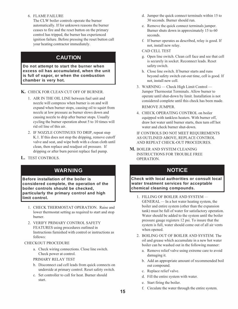
5. CAD CELL LOCATION AND SERVICEThe burner is supplied with a cadmium sulfide flamedetector mounted at the factory, mounted on the Figure 14: Cad Cell Location
Figure 13: Beckett AFG Gun Setting and Electrode Positioning
TABLE 5: BECKETT AFG BURNER
bottom of the electronic ignitor. See Figure 14. Toservice cad cell or to replace the plug in portion,swing open the ignitor. After service is complete, besure to fasten down the ignitor.
relioBledoM
gniriFetaR
riArettuhSgnitteS
dnaBriAgnitteS
daeHcitatScsiD
pmuPerusserP
ataDelzzoN
HPG elgnA epyT .gfM
*3-WLC57.0 7 0 3F U"8/3-3 041 56.0 °08 A navaleD
00.1 01 2 3F U"8/3-3 041 58.0 °08 B navaleD
4-WLC00.1 8 0 3F U"4/3-2 001 00.1 °08 B navaleD
53.1 8 1 6F U"4/3-2 001 53.1 °08 B navaleD
LC W 5-53.1 9 0 6F U"4/3-2 001 52.1 °08 B navaleD
56.1 01 2 6F U"4/3-2 001 56.1 °08 B navaleD
LC W 6-05.1 01 1 6F U"4/3-2 001 05.1 °08 B navaleD
00.2 01 2 61F "4/1-2 001 00.2 °08 B navaleD
3-WLCnodesUsielffaBetaRgniriFwoL*OCdnaekomsybdeifirevebtsumdnaetamixorppaerasgnitteS 2 .tnemerusaem
.launaMehtfotxeTeeS.yrassecenerehwtsujdaeR
15
d. Jumper the quick connect terminals within 15 to30 seconds. Burner should run.
e. Remove the quick connect terminals jumper.Burner shuts down in approximately 15 to 60seconds.
f. If burner operates as described, relay is good. Ifnot, install new relay.
CAD CELL TESTg. Open line switch. Clean cell face and see that cell
is securely in socket. Reconnect leads. Resetsafety switch.
h. Close line switch. If burner starts and runsbeyond safety switch cut-out time, cell is good. Ifnot, install new cell.
3. WARNING — Check High Limit Control —Jumper Thermostat Terminals. Allow burner tooperate until shut-down by limit. Installation is notconsidered complete until this check has been made.REMOVE JUMPER.
4. CHECK OPERATING CONTROL on boilerequipped with tankless heaters. With burner off,draw hot water until burner starts, then turn off hotwater and check burner shut-down.
IF CONTROLS DO NOT MEET REQUIREMENTSAS OUTLINED ABOVE, REPLACE CONTROLAND REPEAT CHECK-OUT PROCEDURES.
M. BOILER AND SYSTEM CLEANINGINSTRUCTIONS FOR TROUBLE FREEOPERATION.
ECITONlacoltlusnocroseitirohtualacolhtiwkcehC
elbatpeccarofsecivrestnemtaertretaw.sdnuopmocgninaelclacimehc
1. FILLING OF BOILER AND SYSTEM —GENERAL — In a hot water heating system, theboiler and entire system (other than the expansiontank) must be full of water for satisfactory operation.Water should be added to the system until the boilerpressure gauge registers 12 psi. To insure that thesystem is full, water should come out of all air ventswhen opened.
2. BOILING OUT OF BOILER AND SYSTEM. Theoil and grease which accumulate in a new hot waterboiler can be washed out in the following manner:a. Remove relief valve using extreme care to avoid
damaging it.b. Add an appropriate amount of recommended boil
out compound.c. Replace relief valve.d. Fill the entire system with water.e. Start firing the boiler.f. Circulate the water through the entire system.
6. FLAME FAILUREThe CLW boiler controls operate the burnerautomatically. If for unknown reasons the burnerceases to fire and the reset button on the primarycontrol has tripped, the burner has experiencedignition failure. Before pressing the reset button callyour heating contractor immediately.
NOITUACnehwrenrubehttratsottpmettatonoD
tinuehtnehw,detalumuccasahliossecxenoitsubmocehtnehwro,ropavfollufsi
.tohyrevsirebmahc
K. CHECK FOR CLEAN CUT OFF OF BURNER.
1. AIR IN THE OIL LINE between fuel unit andnozzle will compress when burner is on and willexpand when burner stops, causing oil to squirt fromnozzle at low pressure as burner slows down andcausing nozzle to drip after burner stops. Usuallycycling the burner operation about 5 to 10 times willrid oil line of this air.
2. IF NOZZLE CONTINUES TO DRIP, repeat stepK.1. If this does not stop the dripping, remove cutoffvalve and seat, and wipe both with a clean cloth untilclean, then replace and readjust oil pressure. Ifdripping or after burn persist replace fuel pump.
L. TEST CONTROLS.
GNINRAWsireliobehtfonoitallatsnierofeB
ehtfonoitarepoeht,etelpmocderedisnoc,dekcehcebdluohsslortnocreliob
hgihdnalortnocyramirpehtylralucitrap.lortnoctimil
1. CHECK THERMOSTAT OPERATION. Raise andlower thermostat setting as required to start and stopburner.
2. VERIFY PRIMARY CONTROL SAFETYFEATURES using procedures outlined inInstructions furnished with control or instructions asfollows:
CHECKOUT PROCEDUREa. Check wiring connections. Close line switch.
Check power at control.PRIMARY RELAY TESTb. Disconnect cad cell leads from quick connects on
underside at primary control. Reset safety switch.c. Set controller to call for heat. Burner should
start.

16
g. Vent the system, including the radiation.h. Allow boiler water to reach operating
temperature, if possible.i. Continue to circulate the water for a few hours.j. Stop firing the boiler.k. Drain the system in a manner and to a location
that hot water can be discharged with safety.l. Remove plugs from all available returns and
wash the water side of the boiler as thoroughly aspossible, using a high-pressure water stream.
m. Refill the system with fresh water.3. Add appropriate boiler water treatment compounds
as recommended by your qualified water treatmentcompany.
O. HINTS ON COMBUSTION1. NOZZLES — Although the nozzle is a relatively
inexpensive device, its function is critical to thesuccessful operation of the oil burner. The selectionof the nozzle supplied with the CLW boiler is theresult of extensive testing to obtain the best flameshape and efficient combustion. Other brands of thesame spray angle and spray pattern may be used butmay not perform at the expected level of CO2 andsmoke. Nozzles are delicate and should be protectedfrom dirt and abuse. Nozzles are mass-produced andcan vary from sample to sample. For all of thosereasons a spare nozzle is a desirable item for aserviceman to have.
2. FUEL LEAKS — Any fuel leak between the pumpand the nozzle will be detrimental to goodcombustion results. Look for wet surfaces in the airtube, under the ignitor, and around the air inlet. Anysuch leaks should be repaired as they may causeerratic burning of the fuel and in the extreme casemay become a fire hazard.
3. AIR LEAKS — Any such leaks should be repaired,as they may cause erratic burning of the fuel and inextreme cases may become a fire hazard.
SUCTION LINE LEAKS -Whatever it takes, The Oil Must Be Free of Air. Thiscan be a tough problem , but it must be resolved. Trybleeding the pump through a clear tube. There must beno froth visible. There are various test kits available toenable you to look at the oil through clear tube. Theremust be no froth visible. There are various test kitsavailable to enable you to look at the oil through cleartubing adapted to the supply line at the pump fitting.Air eliminators are on the market that have potential.Also, electronic sight glasses are being used with goodsuccess. At times, new tubing must be run to the tank ornew fittings put on. Just make sure you get the air outbefore you leave.Any air leaks in the fuel line will cause an unstable
flame and may cause delayed ignition noises. Use onlyflare fittings in the fuel lines.4. GASKET LEAKS — If 11.5 to 12.5% CO2 with a
#1 smoke cannot be obtained in the breeching, lookfor air leaks around the burner mounting gasket,observation door, and canopy gasket. Such air leakswill cause a lower CO2 reading in the breeching. Thesmaller the firing rate the greater effect an air leakcan have on CO2 readings.
5. DIRT — A fuel filter is a good investment.Accidental accumulation of dirt in the fuel systemcan clog the nozzle or nozzle strainer and produce apoor spray pattern from the nozzle. The smaller thefiring rate, the smaller the slots become in the nozzleand the more prone to plugging it becomes with thesame amount of dirt.
6. WATER — Water in the fuel in large amounts willstall the fuel pump. Water in the fuel in smalleramounts will cause excessive wear on the pump, butmore importantly water doesn’t burn. It chills theflame and causes smoke and unburned fuel to passout of the combustion chamber and clog theflueways of the boiler.
7. COLD OIL — If the oil temperature approachingthe fuel pump is 40°F or lower poor combustion ordelayed ignition may result. Cold oil is harder toatomize at the nozzle. Thus, the spray droplets getlarger and the flame shape gets longer. An outsidefuel tank that is above grade or has fuel lines in ashallow bury is a good candidate for cold oil. Thebest solution is to bury the tank and lines deepenough to keep the oil above 40°F.
8. FLAME SHAPE — Looking into the combustionchamber through the observation door, the flameshould appear straight with no sparklers rolling uptoward the crown of the chamber. If the flame dragsto the right or left, sends sparklers upward or makeswet spots on the target wall, the nozzle should bereplaced. If the condition persists look for fuel leaks,air leaks, water or dirt in the fuel as described above.
9. HIGH ALTITUDE INSTALLATIONSAir settings must be increased at high altitudes. Useinstruments and set for 11.5 to 12.5% CO2.
10. START-UP NOISE — Late ignition is the cause ofstart-up noises. If it occurs recheck for electrodesettings, flame shape, air or water in the fuel lines.
11. SHUT DOWN NOISE — If the flame runs out ofair before it runs out of fuel, an after burn withnoise may occur. That may be the result of a faultycut-off valve in the fuel pump, or it may be air
trapped in the nozzle line. It may take several firingcycles for that air to be fully vented through thenozzle. Water in the fuel or poor flame shape can
also cause shut down noises.A very good test for isolating fuel side problems is

17
to disconnect the fuel system and with a 2 ft. lengthof tubing, fire out of an auxiliary five gallon pail ofclean, fresh, warm #2 oil from another source. If theburner runs successfully when drawing out of theauxiliary pail then the problem is isolated to the fuelor fuel lines being used on the jobsite.
P. ATTENTION TO BOILER WHILE NOT INOPERATION
IM TNATROP
IF BOILER IS NOT USED DURING WINTERTIME, IT MUST BE FULLY DRAINED TOPREVENT FREEZE DAMAGE.
1. Spray inside surfaces with light lubricating orcrankcase oil using gun with extended stem so as toreach all corners.
2. Always keep the manual fuel supply valve shut off if
the burner is shut down for an extended period oftime.
3. To recondition the heating system in the fall seasonafter a prolonged shut down, follow the instructionsoutlined in Section III, Items A through L.
NOITUACyamhcihwslortnocsniatnocreliobsihT
tondnanwodtuhsotreliobehtesuacoteudegamadfI.ecivrestuohtiwtratser
gnitaeheht,ytilibissopasisepipnezorfnidednettanutfelebtondluohsmetsyssdraugefasetairporpparo;rehtaewdloc
ehtnodellatsniebdluohssmraladnaehtfiegamadtneverpotmetsysgnitaeh
.evitareponisireliob

18
AQUASTAT SWITCHING ACTION WITHIN L8124CCONTROL
The switching action within the L8124C control hasthree settings:
1. high limit2. low limit3. adjustable differential
HIGH LIMIT OPERATION —-The high limit opens and turns off the burner when the
water temperature reaches the set point. The high limitautomatically resets after the water temperature drops pastthe set point and through the 10°F differential.
Set the indicator at desired shutoff temperature.
LOW LIMIT OPERATION —-On a temperature rise, with the adjustable differential at
the minimum setting of 10°F, the burner circuit (R-B) breaksand the circulator circuit (R-W) makes at the low limit setpoint. On a temperature drop of 10°F below the set point,the R-B circuit makes and the R-W circuit breaks.
ADJUSTABLE DIFFERENTIAL —-At any differential setting greater than 10°F, the R-B
make temperature and R-W break temperature will remainthe same-control setting minus 10°F. The R-B break and R-W make temperature will be the set point temperature plusthe difference between the differential setting and 10°F.
EXAMPLE: Set point of 140°F; differential set at 25°F. Ona temperature rise, R-B will break and R-W will make at155°F. On a temperature fall, R-B will make and R-W willbreak at 130°F.
Set low limit indicator at the minimum temperaturerecommended for domestic hot water supply. This settingmust be at least 20°F below high limit setting to prevent oneswitch from locking out the other.
Set the differential the desired number of degrees. 25°Fdifferential gives longest burner cycles.
AQUASTAT SWITCHING ACTION WITHIN L8148ACONTROLS
The switching action in the L8148A control has onesetting, the high limit. The switching relay is controlled bythe low voltage room thermostat. On a call for heat, the relaycontacts make to complete the line voltage circulator circuitand also the burner circuit if the boiler water temperature isbelow the high limit setting. The high limit switch shuts offthe burner if boiler water temperature exceeds the high limitsetting.
Set the indicator at the desired shutoff temperature.

19
SECTION IV: BOILER CLEANING
Figure 15: Cleaning of Boiler Flueways
A. CLEAN THE FLUEWAYS (See Figure 15).1. Disconnect oil line(s) and remove burner and burner
mounting plate. See Figures 1A and 1B.2. Lay protective cloth or plastic over combustion
chamber blanket.3. On boilers with tankless heaters remove the control
from the tankless heater well. Unfasten the conduitfrom the jacket panel and swing control away fromthe jacket right side.
4. Remove the smokepipe as necessary to gain accessto the boiler canopy.
5. Remove the jacket top and right side panels.NOTE: Top panel must be altered to be maderemovable. Cut away left corner around supplypiping and relief valve. Top panel can be hingedupward for access to canopy.
6. Remove the canopy being careful not to damage thecerafelt gasket.
7. Loosen nuts securing the flue cleanout plates andremove the plates. The insulation should be removedwith the plates taking care not to damage theinsulation.
8. Using a 1¼” diameter wire or fibre bristle brush(30” handle) clean the flueways. Brush from the topand side using horizontal and diagonal strokes forbest results. DO NOT allow brush to strike the targetwall or liner in the chamber.
B. CLEAN TOP OF BOILER SECTIONS.1. Brush and vacuum the tops of the boiler sections.
C. CLEAN THE FIREBOX.1. Using wire or fibre bristle brush, clean crown of
boiler and inside of water legs. DO NOT allowbrush to strike target wall or blanket in thecombustion chamber.
D. AFTER CLEANING, remove protective cloth withdebris and vacuum as necessary, but be careful not todamage blanket. Inspect target wall, combustionchamber blanket and burner mounting plate insulationfor signs of damage. If damaged, replace as needed.
E. REASSEMBLE BOILER.CAUTION: Do not start the burner unless canopy,smokepipe, burner mounting plate and all flue plates aresecured in place.1. Install the canopy taking care to align the gaskets
without blocking the flueways. If gasket is damaged,replace as needed.
2. Bolt burner mounting plate to front section withfasteners.
3. Bolt burner to burner mounting plate and connect oilline(s).
4. Reinstall flue plates, making sure gasket on eachplate is in place and forms gas tight seal. If damagedreplace as needed.
5. Reinstall Right Side Jacket Panel and Top Panel andsecure with sheet metal screws.
6. Reinstall smokepipe on canopy and secure to collarwith sheet metal screws.
7. On boilers with tankless heaters place sensingelement of control well and bottom. Tighten screw.secure cduit to jacket with plastic clips.
GNINRAW.ffodenruthctiwsecivresrenrubhtiwdetelpmocebtsumgninaelcreliobllA
GNINRAWnaotdetcennocebtsumreliobehT
.noitidnocdoogniyenmihcdevorppaehtfitluserdluocegamadytreporpsuoireSetauqedaniroytridaotdetcennocsireliob
eulfyenmihcehtforoiretniehT.yenmihcehterofebdenaelcdnadetcepsniebtsumebdluohsdnanosaesgnitaehehtfotrats
ehttuohguorhtyllacidoirepdetcepsniA.snoitcurtsboynarofnosaesgnitaehsieulfyenmihcdetcurtsbonudnanaelctahtsemufsuoixonwollaotyrassecen
tnevotefilfossolroyrujniesuacdluocdrawotetubirtnoclliwdnaylefas
.ycneiciffes'reliobehtgniniatniam

20
All CLW Series repair parts may be ordered through New Yorker® Boiler Company, or its authorized distributors.Should you require assistance in locating a New Yorker Distributor in your area, or have questions regarding the availability ofNew Yorker products or repair parts, please contact: New Yorker® Boiler Co., Inc., P.O. Box 295, Colmar, PA 18915, Phone:(215) 822-0114 Attn: Customer Service Department
SECTION V: REPAIR PARTS
Figu
re 1
6: B
are
Boi
ler A
ssem
bly
Expl
oded
Vie
w
21
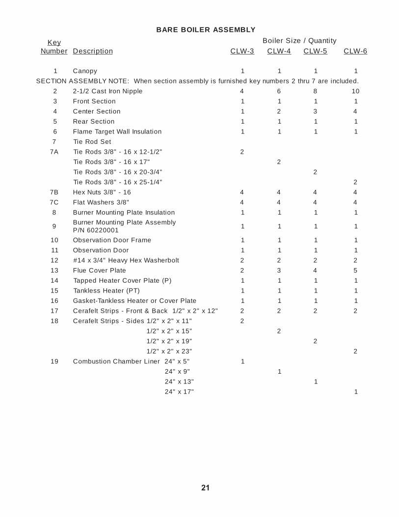
YLBMESSARELIOBERAB
yeKrebmuN noitpircseD
ytitnauQ/eziSrelioB
3-WLC 4-WLC 5-WLC 6-WLC
1 yponaC 1 1 1 1
.dedulcniera7urht2srebmunyekdehsinrufsiylbmessanoitcesnehW:ETONYLBMESSANOITCES
2 elppiNnorItsaC2/1-2 4 6 8 01
3 noitceStnorF 1 1 1 1
4 noitceSretneC 1 2 3 4
5 noitceSraeR 1 1 1 1
6 noitalusnIllaWtegraTemalF 1 1 1 1
7 teSdoReiT
A7 "2/1-21x61-"8/3sdoReiT 2
"71x61-"8/3sdoReiT 2
"4/3-02x61-"8/3sdoReiT 2
"4/1-52x61-"8/3sdoReiT 2
B7 61-"8/3stuNxeH 4 4 4 4
C7 "8/3srehsaWtalF 4 4 4 4
8 noitalusnIetalPgnitnuoMrenruB 1 1 1 1
9ylbmessAetalPgnitnuoMrenruB
10002206N/P1 1 1 1
01 emarFrooDnoitavresbO 1 1 1 1
11 rooDnoitavresbO 1 1 1 1
21 tlobrehsaWxeHyvaeH"4/3x41# 2 2 2 2
31 etalPrevoCeulF 2 3 4 5
41 )P(etalPrevoCretaeHdeppaT 1 1 1 1
51 )TP(retaeHsselknaT 1 1 1 1
61 etalPrevoCroretaeHsselknaT-teksaG 1 1 1 1
71 "21x"2x"2/1kcaB&tnorF-spirtStlefareC 2 2 2 2
81 "11x"2x"2/1sediS-spirtStlefareC 2
"51x"2x"2/1 2
"91x"2x"2/1 2
"32x"2x"2/1 2
91 "5x"42reniLrebmahCnoitsubmoC 1
"9x"42 1
"31x"42 1
"71x"42 1
22
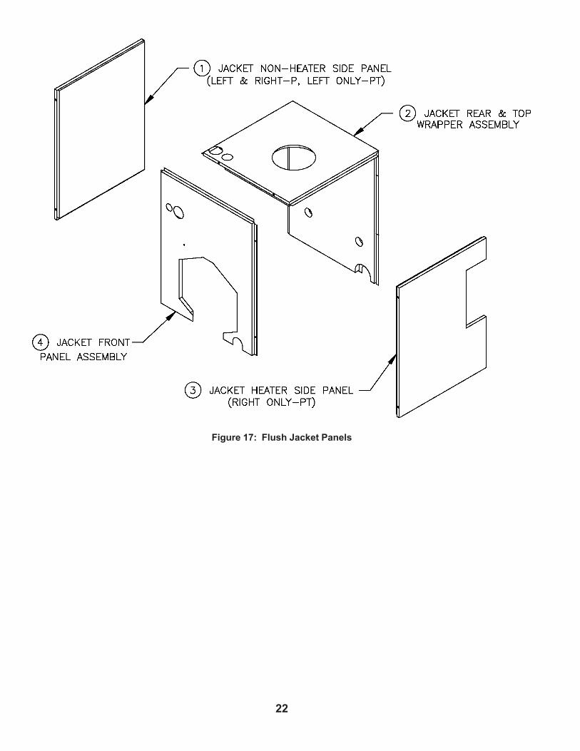
Figure 17: Flush Jacket Panels

23
ylbmessAtekcaJhsulF
yeKrebmuN noitpircseD ytitnauQ
STNENOPMOCTEKCAJHSULF
ylbmessafotrapsanoitalusniedulcni4urht1smetI 1
1 )P(ylbmessAlenaPediSretaeH-noNtekcaJ 2
1 )TP(ylbmessAlenaPediSretaeH-noNtekcaJ 1
2 ylbmessArepparWpoT&raeRtekcaJ 1
3 )TP(ylbmessAlenaPediSretaeHtekcaJ 1
4 ylbmessAlenaPtnorFtekcaJ 1

24
Figure 18: Trim and Controls
ylbmessAslortnoCdnamirT
yeK.oN
noitpircseD yeK.oN
noitpircseD
A1 yalerotcetorP0001A4817R D2 elppiN"7x"¾
B1 yaleR.criC,timiLiH0901A8418L E2 gnihsuB"¾x"½1
C1 .criC,timiLoL&iH2011C4218L F2 evlaVniarD"¾
D1 eguaGerusserP/erutarepmeT"½2 A3 rotalucriC700ocaT
A2 50-704-01#,evlaVfeileR B3 )d'qeR2(egnalFrotalucriC"½1
B2 woblEteertS°09x"¾ C3 )d'qeR2(teksaGegnalFocaT
C2 eeT"¾

25
noitamrofnIytefaStcudorPtnatropmI
tcudorPrebiFcimareCyrotcarfeR
Warning:
This product contains refractory ceramic fibers (RCF). RCF has been classified asa possible human carcinogen. After this product is fired, RCF may, when exposedto extremely high temperature (>1800F), change into a known human carcinogen.When disturbed as a result of servicing or repair, RCF becomes airborne and, ifinhaled, may be hazardous to your health.
AVOID Breathing Fiber Particulates and Dust
Precautionary Measures:
Do not remove or replace previously fired RCF (combustion chamber insulation,target walls, canopy gasket, flue cover gasket, etc.) or attempt any service orrepair work involving RCF without wearing the following protective gear:
1. A National Institute for Occupational Safety and Health (NIOSH)approved respirator
2. Long sleeved, loose fitting clothing3. Gloves4. Eye Protection
• Take steps to assure adequate ventilation.• Wash all exposed body areas gently with soap and water after contact.• Wash work clothes separately from other laundry and rinse washing
machine after use to avoid contaminating other clothes.• Discard used RCF components by sealing in an air tight plastic bag.
First Aid Procedures:
• If contact with eyes: Flush with water for at least 15 minutes. Seekimmediate medical attention if irritation persists.
• If contact with skin: Wash affected area gently with soap and water.Seek immediate medical attention if irritation persists.
• If breathing difficulty develops: Leave the area and move to a locationwith clean fresh air. Seek immediate medical attention if breathingdifficulties persist.
• Ingestion: Do not induce vomiting. Drink plenty of water. Seekimmediate medical attention.
26
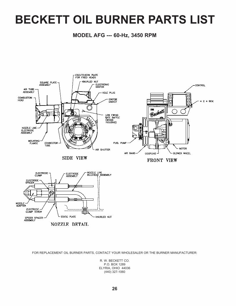
BECKETT OIL BURNER PARTS LISTMODEL AFG --- 60-Hz, 3450 RPM
FOR REPLACEMENT OIL BURNER PARTS, CONTACT YOUR WHOLESALER OR THE BURNER MANUFACTURER:
R. W. BECKETT CO.P.O. BOX 1289
ELYRIA, OHIO 44036(440) 327-1060
27
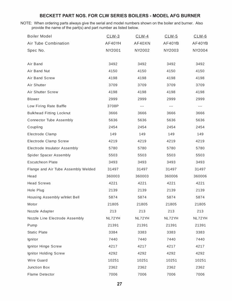
BECKETT PART NOS. FOR CLW SERIES BOILERS - MODEL AFG BURNERNOTE: When ordering parts always give the serial and model numbers shown on the boiler and burner. Also provide the name of the part(s) and part number as listed below.
ledoMrelioB 3-WLC 4-WLC 5-WLC 6-WLC
noitanibmoCebuTriA HY04FA NX04FA BY04FA BY04FA
.oNcepS 1002YN 2002YN 3002YN 4002YN
dnaBriA 2943 2943 2943 2943
tuNdnaBriA 0514 0514 0514 0514
wercSdnaBriA 8914 8914 8914 8914
rettuhSriA 9073 9073 9073 9073
wercSrettuhSriA 8914 8914 8914 8914
rewolB 9992 9992 9992 9992
elffaBetaRgniriFwoL P8073 --- --- ---
tunkcoLgnittiFdaehkluB 6663 6663 6663 6663
ylbmessAebuTrotcennoC 6365 6365 6365 6365
gnilpuoC 4542 4542 4542 4542
pmalCedortcelE 941 941 941 941
wercSpmalCedortcelE 9124 9124 9124 9124
ylbmessArotalusnIedortcelE 0875 0875 0875 0875
ylbmessArecapSredipS 3055 3055 3055 3055
etalPnoehctucsE 3943 3943 3943 3943
dedleWylbmessAebuTriAdnaegnalF 79413 79413 79413 79413
daeH 300063 300063 600063 600063
swercSdaeH 1224 1224 1224 1224
gulPeloH 9312 9312 9312 9312
lleBtelnI/wylbmessAgnisuoH 4785 4785 4785 4785
rotoM 50812 50812 50812 50812
retpadAelzzoN 312 312 312 312
ylbmessAedortcelEeniLelzzoN HY27LN HY27LN HY27LN HY27LN
pmuP 19312 19312 19312 19312
etalPcitatS 4833 3833 3833 3833
rotingI 0447 0447 0447 0447
wercSegniHrotingI 7124 7124 7124 7124
wercSgnidloHrotingI 2924 2924 2924 2924
drauGeriW 01 52 1 15201 15201 15201
xoBnoitcnuJ 2632 2632 2632 2632
rotceteDemalF 6007 6007 6007 6007
28 M24200R3-7/03
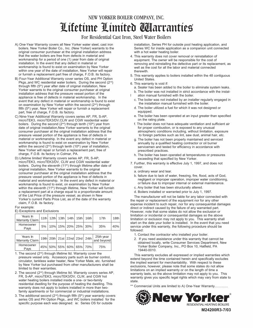
A) One-Year Warranty covers all New Yorker water steel, cast ironboilers. New Yorker Boiler Co., Inc. (New Yorker) warrants to theoriginal consumer purchaser at the original installation addressthat the water boilers are free from defects in material andworkmanship for a period of one (1) year from date of originalinstallation. In the event that any defect in material orworkmanship is found to exist on examination by New Yorkerwithin one year of the date of installation, New Yorker will repairor furnish a replacement part free of charge, F.O.B. its factory.
B) Four-Year Additional Warranty cover series OS, and PH OptionPkgs.,and WC residential water boilers. During the second (2nd)through fifth (5th) year after date of original installation, NewYorker warrants to the original consumer purchaser at originalinstallation address that the pressure vessel portion of theappliance is free of defects in material workmanship. In theevent that any defect in material or workmanship is found to existon examination by New Yorker within the second (2nd) throughfifth (5th) year, New Yorker will repair or furnish a replacementpart, free of charge, F.O.B. its factory.
C) Nine-Year Additional Warranty covers series AP, FR, S-AP,microTEK3, microTEK3/DV,CLW and CGW residential waterboilers. During the second (2nd) through tenth (10th) year fromdate of original installation,New Yorker warrants to the originalconsumer purchaser at the original installation address that thepressure vessel portion of the appliance is free of defects inmaterial or workmanship. In the event any defect in material orworkmanship is found to exist on examination by New Yorkerwithin the second (2nd) through tenth (10th) year of installation,New Yorker will repair or furnish a replacement part, free ofcharge, F.O.B. its factory in Colmar, PA.
D) Lifetime limited Warranty covers series AP, FR, S-AP,microTEK3, microTEK3/DV, CLW and CGW residential waterboilers. During the eleventh (11th) through lifetime after date oforiginal installation, New Yorker warrants to the originalconsumer purchaser at the original installation address that thepressure vessel portion of the appliance is free of defects inmaterial and workmanship. In the event any defect in material orworkmanship is found to exist, on examination by New Yorkerwithin the eleventh (11th) through lifetime, New Yorker will furnisha replacement part at a charge equal to a proportionate amountof the List Price of the pressure vessel, as shown in NewYorker’s current Parts Price List, as of the date of the warrantyclaim, F.O.B. its factory.
For example:E) Exceptions and Exclusions
1. The second (2nd) through lifetime ltd. Warranty cover thepressure vessel only. Accessory parts such as burner control,circulator, tankless water heater, New Yorker Mate, etc. furnishedby New Yorker but purchased from other manufacturers shall belimited to their warranties.
2. The second (2nd) through lifetime ltd. Warranty covers series AP,FR, S-AP, microTEK3, microTEK3/DV, CLW, and CGW hotwater heating boilers installed inside a one- or two-familyresidential dwelling for the purpose of heating the dwelling. Thiswarranty does not apply to boilers installed in more than two-family apartments or for commercial or industrial installations.
3. The additional second (2nd) through fifth (5th) year warranty coversseries OS and PH Option Pkgs., and WC boilers installed for thespecific purpose each was designed: ie: Series OS for outside
installation, Series PH for outside pool heating application, andSeries WC for inside application as a companion unit connectedwith a hot water heating boiler.
4. This warranty does not cover removal or reinstallation ofequipment. The owner will be responsible for the cost ofremoving and reinstalling the defective part or its replacement, aswell as the cost for all the labor and material connectedtherewith.
5. This warranty applies to boilers installed within the 48 contiguousUnited States.
6. This warranty is void if:a. Sealer has been added to the boiler to eliminate system leaks.b. The boiler was not installed in strict accordance with the instal-
l ation manual furnished with the boiler.c. The boiler was not installed by an installer regularly engaged in
the installation manual furnished with the boiler.d. The boiler utilized a fuel for which it was not designed or
equipped.e. The boiler has been operated at an input greater than specified
on the rating plate.f. The boiler does not have adequate ventilation and sufficient air
for proper combustion, or is exposed to any unusualatmospheric conditions including, without limitation, exposure to foreign particles such as lint, saw dust, animal hair, etc.
g. The boiler has not been properly maintained and servicedannually by a qualified heating contractor or oil burnerservicemen and tested for efficiency in accordance withprescribed practices.
h. The boiler has been operated at temperatures or pressuresexceeding that specified by New Yorker.
7. Further, this warranty is effective July 1, 1997, and does notcover.a. ordinary wear and tear.b. failure due to lack of water, freezing, fire, flood, acts of God,
negligent or improper operation, improper water conditioning,or failure due to improper internal or external maintenance.
c. Any boiler that has been structurally altered.d. Boilers installed or warranted prior to July 1, 1997.The manufacturer will not be liable for any labor connected with
the repair or replacement of the equipment nor for any otherexpense incident to such repair, nor for any consequential damagesdirect or indirect caused by the failure of any warranted part.However, note that some states do not allow the exclusion orlimitation or incidental or consequential damages so the abovelimitation or exclusion may not apply to you. This warranty shallstart on the date your boiler is installed. In the event that you needservice under this warranty, the following procedure should befollowed:
1. Contact the contractor who installed your boiler.2. If you need assistance under this warranty that cannot be
obtained locally, write Consumer Services Department, NewYorker Boiler Company, Inc., PO Box 10, Hatfield, PA19440-0010.
This warranty excludes all expressed or implied warranties whichextend beyond the time contained herein and specifically excludesthe implied warrant for merchantability. With respect to theseexclusions, however, please note that some states do not allowlimitations on an implied warranty or on the length of time awarranty lasts, so the above limitation may not apply to you. Thiswarranty gives you specific legal rights which may vary from state tostate.** Commercial Units are limited to A) One-Year Warranty…………
NEW YORKER BOILER COMPANY, INC.
Lifetime Limited WarrantiesFor Residential Cast Iron, Steel Water Boilers
nIsraeYmialCytnarraW ht11 ht21 ht31 ht41 ht51 ht61 ht71 ht81
renwoemoHsyaP %5 %01 %51 %02 %52 %03 %53 %04
nIsraeYmialCytnarraW ht91 ht02 ts12 dn22 dr32 ht42 raeyht52
dnoyebdnarenwoemoH
syaP %54 %05 %55 %06 %56 %07 %57