installation, operation and maintenance instruction · phone +41 61 833 70 70 fax +41 61 833 70 71...
TRANSCRIPT

phone +41 61 833 70 70 fax +41 61 833 70 71 [email protected] www.invent-armaturen.ch
External Monobloc Pumps Series MBBasic Version
Installation, Operation and Maintenance Instruction
phone +41 61 833 70 70 fax +41 61 833 70 71 [email protected] www.invent-armaturen.ch
END-USER MANUAL 3
Contents: page
1. FOREWORD ...........................................................................................................................• •.....42. GUARANTEE • • • • • • • • • •...........................................................................................................• •.. 43. SAFETY AND ENVIRONMENT .................................................................................................• •.. 5
3.1 Symbols ................................................................................................................................……….. 5 3.2 General safety instructions...........................................................................................................……….. 5 3.3 Environment ................................................................................................................................………..5
4. TECHNICAL DATA .....................................................................................................................• •..6 4.1 General ......................................................................................................................................……….. .6 4.2 Main parts ...................................................................................................................................……….. 6 4.3 Sound level………………………………………………………………………………………………………… 7
5. CHECK POINTS BEFORE INSTALLATION :...............................................................................• • 85.1 Delivery check .............................................................................................................................………..8
5.2 Oil level .......................................................................................................................................………..8 5.3 Power supply ..............................................................................................................................………...8 5.4 Motor protection................................................................................................................................….…8 5.5 Electromotor ..........................................................................................................................…………….8 5.6 Pump seals..........................................................................................................................………………8 5.7 Installation ts......................................................................................................................................……8
6. FIRST PUMP START .................................................................................................................• •.. 9 6.1 Direction of rotation ........................................................................................................................…….. 9 6.2 Current-check.......................................................................................................................................... 9 6.3 Start frequency ……............................................................................................................................... 9
7. INSTALLATION OPTIONS • •.......................................................................................................• •.10 7.1 General ...................................................................................................................................................10 7.2 Installation - H ...........................................................................................................................…………10 7.3 Installation - V..........................................................................................................................................11 7.4 Istallation –SH and –SV ….......................................................................................................................11 7.5 Installation – K …....................................................................................................................................12 7.6 Maximum flange forces and moments .......................................................................................…………13
8. MAINTENANCE ...........................................................................................................................• •.148.1 General ……………………………………………………………………………………………………………….14
8.2 Maintenance schedule …………………………………………………………………………………………….. 14 8.3 Lubricants …………………………………………………………………………………………………………….14 8.4 Oil level ……………………………………………………………………………………………………………....14 8.5 Oil change ……………………………………………………………………………………………………………14 8.6 Flexible coupling …………………………………………………………………………………………………….15
9. TRANSPORT AND STORAGE ....................................................................................................• •.16 10. OPTIONS ..............................................................................................................• • • • • • • • • • • • • •.16 10.1 Seal flushing ………………………………………………………………………………………………16 11. TROUBLE SHOOTING • • • • • • • • • • • • • • • • • • • • • • • • • • • • • • • •.• • • • • • • • • • • • • • • • • • • • • • • • • • • • • •.. 17 APPENDIX 1 : Dataplate .................................................................................................................• •18 APPENDIX 2 : Example of a direct start (DOL) diagram ..............................................................• •.19 APPENDIX 3 : Notes • • • • • • • • • •..........................................................................................................20 WARRANTY AND WARRANTY RECEIPT ...........................................................................................21

phone +41 61 833 70 70 fax +41 61 833 70 71 [email protected] www.invent-armaturen.ch
END-USER MANUAL 4
1. FOREWORD
You are to be congratulated on choosing a pump,which will undoubtedly serve you both reliably andeconomically for a long time, providing you observethe Maintenance Instructions given in this booklet.
The MB / BG pump is a Non-Clogging Vortex pumpdesigned to pump sewage and other solidscontaining waste water.Proper use and maintenance will prolong theoperational life of your F.I.P.S. pump.
This manual contains different warnings and safetyprescription.
When you order spare-parts, please always quote :
1. Pump type2. Code3. Serial number
This information are found on the data-plate(See appendix 1).
Sectional drawings and part lists are available onrequest.
Read this booklet properly, so that dangeroussituations, physical injury or damage can be avoided.
The MB / BG pump is designedfor professional use only. Serviceand maintenance may be doneonly by authorised personal, afterreading this manual.
All products manufactured by F.I.P.S. S.r.l. aremade with great care and according to our highinternal standards. Should you however have anysuggestion concerning our pump range or thisinstruction manual, which will contribute to thequality of our product, please do not hesitate tocontact us to our address:
F.I.P.S. S.r.l.Fabbrica Italiana Pompe SommergibiliV.le Toscana 4620089 ROZZANO (MI) - ItalyTel. 0039-2-8258923 - 57510371Fax 0039-2-57512095e-mail: [email protected] site: www.fips-pumps.it
The2. GUARANTEE
We refer to the warranty agreement with your local dealer.

phone +41 61 833 70 70 fax +41 61 833 70 71 [email protected] www.invent-armaturen.ch
END-USER MANUAL 5
3. SAFETY AND ENVIRONMENT
3.1 Symbols
In this manual
General warning Danger!
Electrical hazard!
Attention!
On the pump
Danger of physical injury!Rotating parts!
Electrical hazard!
EC - conformity symbol
3.2 General safety instructions
Only trained and authorized personal may install and maintain the pump after careful reading of this manual
Only use the pump for its intended purpose and under the regulated circumstances.
Don’t stay near rotating parts
Clean the pump before maintenance and inspection
Observe the local regulations when working with aggressive, corrosive, toxic, flammable and explosive chemicals.
Never remove safety signs, keep them clean
Always connect to a grounded circuit
Before maintenance and inspection always disconnect the pump from the mains.
Use a proper handle for lifting and handling the pump.
Do not leave a large loop of cable in the sump, as the pump may eventually damage it.
Never drop the loose cable end in water. The water may enter the cable and finally enter the motor housing, eventually causing motor failure.
3.3 Environment
The use of a toxin-free lubricating oil, will help prevent pollution of the environment.
Parts which are replaced during repair, maintenance or renewal, could contain materials which could be harmful to the environment.
Please take care in the disposal of these parts.Do this in accordance with the local environmental regulations.

phone +41 61 833 70 70 fax +41 61 833 70 71 [email protected] www.invent-armaturen.ch
END-USER MANUAL 6
4. TECHNICAL DATA
4.1. General
The MB / BG pumps are vortex impeller pumps, designed to pump a wide variety of solids contaminated liquids.
The hydraulic components of the pumps are made in NIHARD IV.These pumps are suitable for dredging, mining and other industry applications.
The impeller leaves a wide unobstructed passage through the volute , in which a strong vortex is created that carries most of the solids.
Construction: Two independent mechanical seals, running in
oil, form an effective barrier between pump and motor
Heavy duty bearings, greased for live Clog-free vortex impeller. Vanes at the backside prevent solids entering the
seal area and reduce the pressure on the seal.
4.2 Main parts
BG with bearing unit
1 Pump casing2 Impeller3 Suction4 Delivery5 Bearing housing6 Pump shaft7 Mechanical seal pump side8 Seal driven side9 Bearing10 Oil tank11 Oil plug 12 Drain plug13 Connection pression gauge
Fig. 4.1
Fig. 4.2
BG short coupled version
1 Pump casing2 Impeller3 Suction4 Delivery5 Motor support6 Motor7 Mechanical seal pump side8 Seal driven side
10 Oil tank11 Oil plug with gauge rod

phone +41 61 833 70 70 fax +41 61 833 70 71 [email protected] www.invent-armaturen.ch
END USER MANUAL 7
4.3 Sound levelDepending on duty point and speed, the pump will produce a certain sound level.Next to this the piping system may produce some noise and vibration.By altering the pipe support and using rubber compensators the vibration will be reduced.
In the next table the sound levels of the MB/BG pumps are shown.
Sound levels BG and MB pumps
Type speed sound level [min-1] [dB]
BG20 960-2900 <60 BG40 960-2900 <60 BG60 960-1450 <60 BG60 2900 <80
MB40 960-1450 <60 MB60 960-1450 <60

phone +41 61 833 70 70 fax +41 61 833 70 71 [email protected] www.invent-armaturen.ch
END USER MANUAL 8
5. CHECK POINTS BEFORE INSTALLATION
After unpacking the pump, carry out the following check points :
5.1 Delivery checkCheck for possible transport damage.
Check for complete delivery
In case that delivery is incomplete or damaged, please, contact your dealer immediately.
5.2 Oil levelCheck the oil level in the oil tank The oil plug has a gauge rod and the level should be between the 2 marks.
5.3 Power supplyBefore making the electrical connections, check if the line voltage and frequency are the same as on the pump data plate.If thermostats are supplied make sure that they are correctly connected.For examples of electrical diagrams and pump cable coding, see appendix 2,3 and 4.
5.4 Motor protectionThe pump should always be connected to the line by means of a suitable motor protection circuit-breaker.If the pump is started Direct-On-Line (DOL), the protection breaker should be set to the current, as given on the data plate.For star delta starting (Y/), it’s good practice to install the over current relay directly after the main contactor. In this case, the pump is also adequately protected in star-connection. The maximum setting of the over current relay is 0.6 x the current as given on the data-plate.It is good practice to set the protection breaker to 10% lower current, because all breakers require at least 110% of the adjusted current before tripping.
5.5 Motor checkIf in doubt about the condition of the motor, Megger test motorwindings against grounding wire. The value should be at least 1 Mohm.
5.6 Pump seals Turn the impeller clockwise by hand, using a proper socket wrench (see fig. 5.1). With this procedure sticking mechanical seal surfaces will be loosened smoothly.
5.7 InstallationCheck if all components for your installation are delivered. See also chapter 6.

phone +41 61 833 70 70 fax +41 61 833 70 71 [email protected] www.invent-armaturen.ch
END USER MANUAL 9
6. FIRST PUMPSTART
6.1 Direction of rotationA correct direction of rotation is essential forproper operation. This can be checked as follows:Check the direction of rotation with the arrow on the pump casing.This can be done by observing the direction of rotation of the motor or coupling
6.2 Current-checkThe current must be checked during normal operation.Apply an ammeter to one of the phase wires and check that the current is not higher than the value on the motor data plate. If so check for:
Voltage (too low)?
Specific gravity or viscosity of the fluid (too high)?
Blocked impeller?
Correct direction sense ?
If the problem cannot be solved contact your dealer.
6.3 Start frequency
When the pump is controlled by level regulators, the ON and OFF levels should be adjusted in such a way that the pump does not do more than 20 starts per hour.

phone +41 61 833 70 70 fax +41 61 833 70 71 [email protected] www.invent-armaturen.ch
END USER MANUAL 10
Fig. 7.1
Fig. 7.2
Fig. 7.3
7. INSTALLATION OPTIONS7.1 General:For the MB/BG pumps the following installations are possible:
H Horizontal, on base plate V Vertical, on supportSH Short coupled, horizontalSV Short coupled, verticalK V-belt driven
7.2 Installation type HHorizontal, on base plate.See fig. 7.1 The main parts are:1. pump unit;2. bearing unit;3. flexible spacer coupling; 4. protection hood;5. electromotor;6. base plate;7. fixing bolts;8. delivery pipe;9 suction pipe;
Checkpoints before operation: - fixation of the base plate to the floor, see fig. 7.1
pos. 7- flanges straight horizontal and vertical see fig. 7.2 pos. 1.- pump and motor shaft aligned, see 7.2.1.- maximum flange forces and moments, see 7.5 - adjust start and stop levels in such a way that the pump does not make more than 20 starts per hours
7.2.1 Alignment of pump and motor shaftAfter the base plate is fixed to the floor, the alignment of pump and motor shaft must be checked.When the base plate is fixed to the floor, forces on the base plate might have disturbed the alignment.Remove the protection hood, (see fig. 7.1 pos. 4).Check for:1. radial deflection (R) max 0.4mm.2. angular deflection (A) max. 1°See fig. 7.3
To correct the alignment, use skims underneath the motor and pump fixing bolts.
Reinstall the protection hood in the original position.
phone +41 61 833 70 70 fax +41 61 833 70 71 [email protected] www.invent-armaturen.ch
END USER MANUAL 11
Fig. 7.4
Fig. 7.5
Fig. 7.6
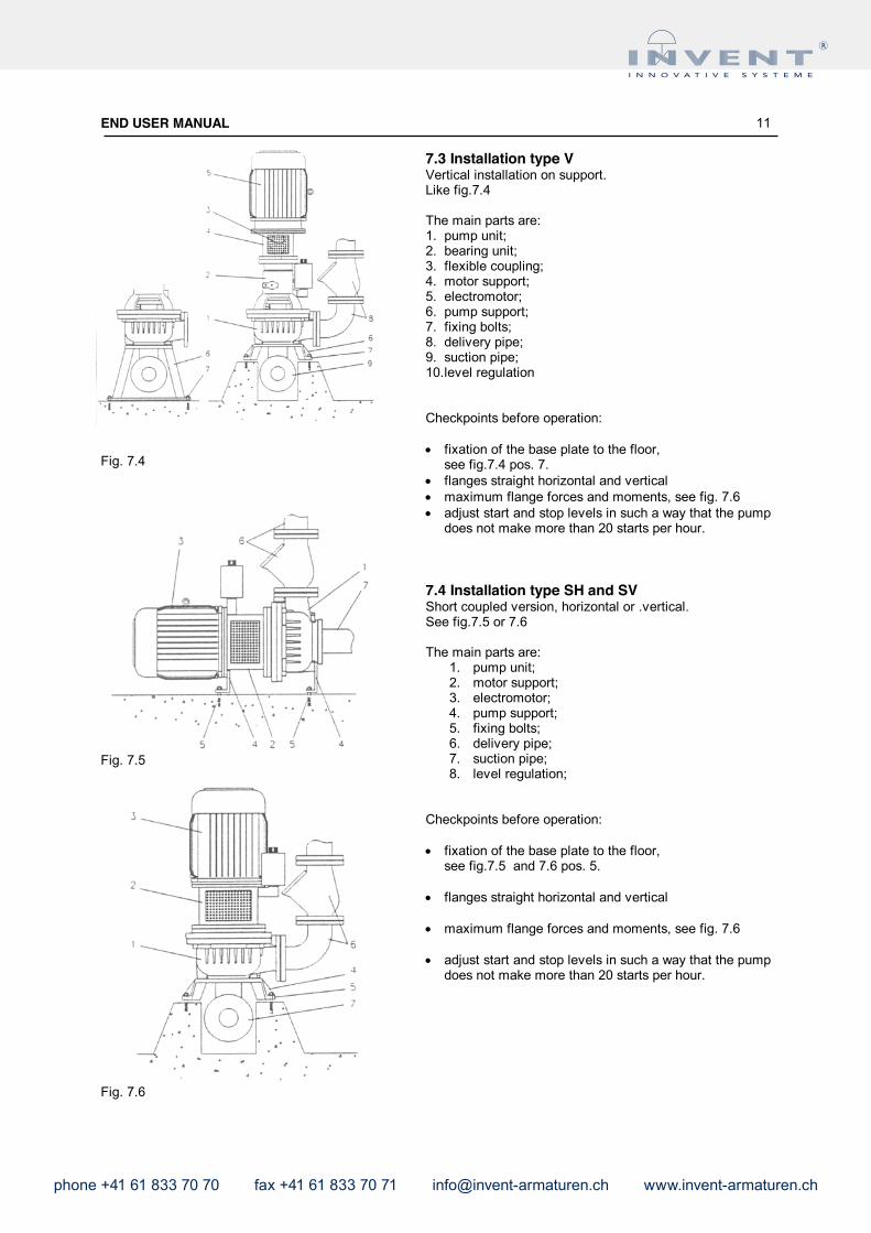
7.3 Installation type VVertical installation on support.Like fig.7.4
The main parts are:1. pump unit;2. bearing unit;3. flexible coupling;4. motor support;5. electromotor;6. pump support;7. fixing bolts;8. delivery pipe;9. suction pipe;10.level regulation
Checkpoints before operation:
fixation of the base plate to the floor, see fig.7.4 pos. 7.
flanges straight horizontal and vertical maximum flange forces and moments, see fig. 7.6 adjust start and stop levels in such a way that the pump
does not make more than 20 starts per hour.
7.4 Installation type SH and SVShort coupled version, horizontal or .vertical.See fig.7.5 or 7.6
The main parts are:1. pump unit;2. motor support;3. electromotor;4. pump support;5. fixing bolts;6. delivery pipe;7. suction pipe;8. level regulation;
Checkpoints before operation:
fixation of the base plate to the floor, see fig.7.5 and 7.6 pos. 5.
flanges straight horizontal and vertical
maximum flange forces and moments, see fig. 7.6
adjust start and stop levels in such a way that the pump does not make more than 20 starts per hour.

phone +41 61 833 70 70 fax +41 61 833 70 71 [email protected] www.invent-armaturen.ch
END USER MANUAL 12
Fig. 7.7
Fig. 7.8
7.5 Installation type KV-belt driven with high placed motor and frame. (see fig.7.7)
The main parts are:1. pump unit;2. bearing unit;3. pulleys;4. tensioned;5. electromotor;6. frame;7. protection plate (2x);8. fixing bolts (4x);9. delivery pipe;10. suction pipe;11. level regulation;
Checkpoints before operation: fixation of the base plate to the floor,
see fig.7.7 pos. 8. flanges straight horizontal and vertical maximum flange forces and moments, see fig. 7.6 adjust start and stop levels in such a way that the pump
does not make more than 20 starts per hour. correct tension of the V-belts. (see fig. 7.5.1)
7.5.1 Tension of the V-beltsCheck the correct tension of the V-belts are follows:Remove one of the protection plates.Put a force of 75N on one of the V-belts in the middle ofthe 2 pulleys, see fig. 7.8.The pressing-in (A) must be about 1 cm.In the value too small (tension too high), move the electromotor (1) downwards.Is the value too high (tension too low), move the electromotor upwards.The difference between the 3 belts may not be more than 0.5 cm. In that case renew all 3 V-belts.
To move the electromotor, use the tensioning rail (2).Place both tensioners (3) underneath the motor.Loosen the motor fixing bolts a bit, and screw-in the tensioners (taut) or screw-out (slack), until the correct tension is reached. Retention the fixing bolts of the motor, and recheck the tension again.
Check afterwards if both pulleys are still aligned (see Fig. 7.9)
phone +41 61 833 70 70 fax +41 61 833 70 71 [email protected] www.invent-armaturen.ch
END USER MANUAL 13
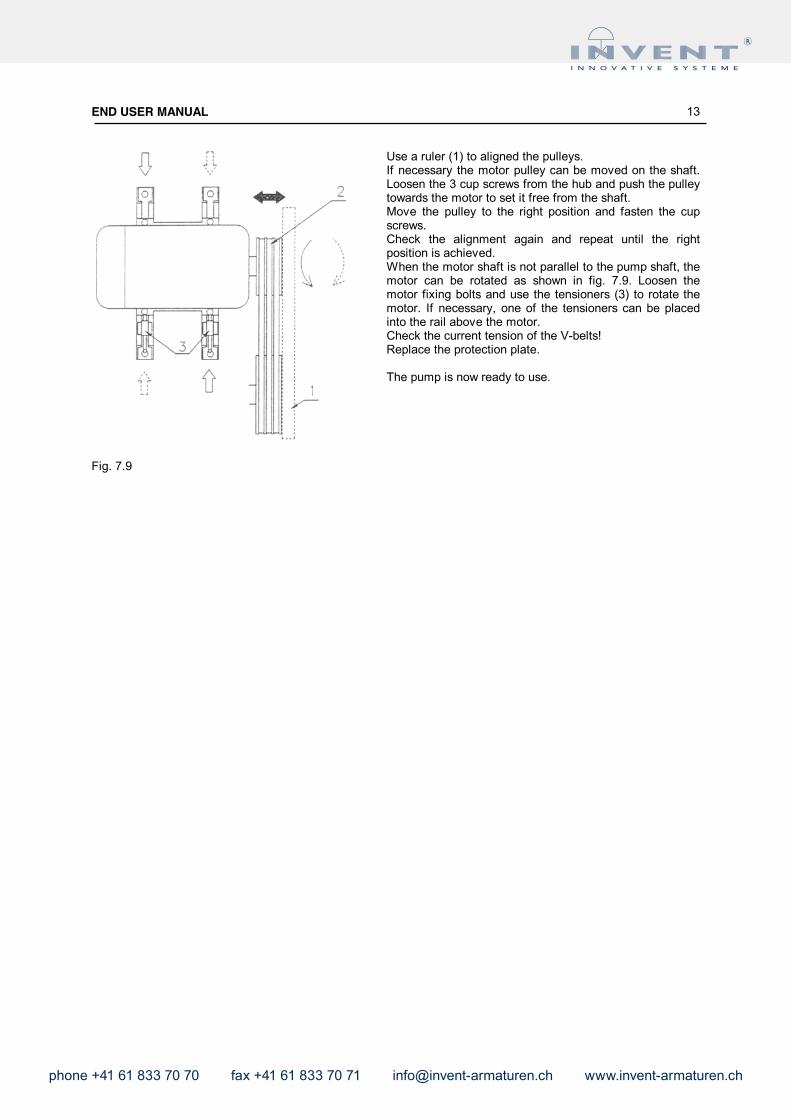
Fig. 7.9
Use a ruler (1) to aligned the pulleys.If necessary the motor pulley can be moved on the shaft. Loosen the 3 cup screws from the hub and push the pulley towards the motor to set it free from the shaft.Move the pulley to the right position and fasten the cup screws.Check the alignment again and repeat until the right position is achieved.When the motor shaft is not parallel to the pump shaft, the motor can be rotated as shown in fig. 7.9. Loosen the motor fixing bolts and use the tensioners (3) to rotate the motor. If necessary, one of the tensioners can be placed into the rail above the motor. Check the current tension of the V-belts!Replace the protection plate.
The pump is now ready to use.

phone +41 61 833 70 70 fax +41 61 833 70 71 [email protected] www.invent-armaturen.ch
END USER MANUAL 14
8. MAINTENANCE
8.1 General
Always disconnect the pump from the mains before inspection or disassembly.
Clean the pump thoroughly.
8.2 Maintenance schedule
After the first 20 running hours:Check the oil level (see chapter 5.2).If more than few drops of water are present in the oil, contact your dealer.
Every 6 months or 500 running hours:Check the oil and oil level (see chapter 5.2).If there is more than few cm³ of water in it, contact your dealer
Refresh the oil every year or when it is no longer transparent. (see chapter 8.5)
8.3 Lubricants
The bearings are long-life greased and they need no refill.
Normally the oil reservoir is filled with Shell Naturelle HF-R or an equivalent.This oil is environmental friendly but can also be mixed with a mineral type.When another kind of oil is used this is marked on a label on the pump.
8.4 Oil levelCheck the oil level in the oil tank.The oil plug has a gauge rod and the level should be between the 2 marks.
8.5 Oil change
Collection, storage and removal of the oil should be done according to the regulations of local authorities.
Always use the right kind of oil!
To drain the oil, remove one of the oil pipes, or use the drain pipe (not applicable for all types).
We advise to flush the system with fresh oil, before filling it up.
phone +41 61 833 70 70 fax +41 61 833 70 71 [email protected] www.invent-armaturen.ch
END USER MANUAL 15
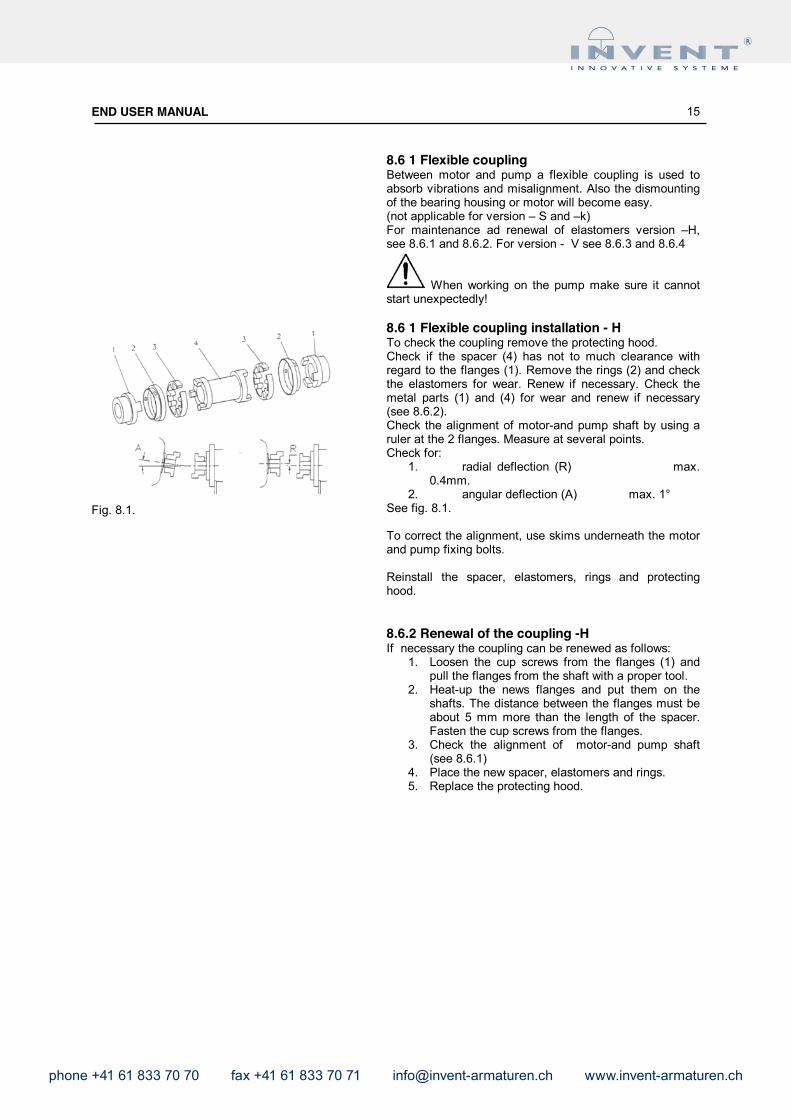
Fig. 8.1.
8.6 1 Flexible coupling Between motor and pump a flexible coupling is used to absorb vibrations and misalignment. Also the dismounting of the bearing housing or motor will become easy.(not applicable for version – S and –k)For maintenance ad renewal of elastomers version –H, see 8.6.1 and 8.6.2. For version - V see 8.6.3 and 8.6.4
When working on the pump make sure it cannot start unexpectedly!
8.6 1 Flexible coupling installation - HTo check the coupling remove the protecting hood.Check if the spacer (4) has not to much clearance with regard to the flanges (1). Remove the rings (2) and check the elastomers for wear. Renew if necessary. Check the metal parts (1) and (4) for wear and renew if necessary (see 8.6.2).Check the alignment of motor-and pump shaft by using a ruler at the 2 flanges. Measure at several points.Check for:
1. radial deflection (R) max. 0.4mm.
2. angular deflection (A) max. 1°See fig. 8.1.
To correct the alignment, use skims underneath the motor and pump fixing bolts.
Reinstall the spacer, elastomers, rings and protecting hood.
8.6.2 Renewal of the coupling -HIf necessary the coupling can be renewed as follows:
1. Loosen the cup screws from the flanges (1) and pull the flanges from the shaft with a proper tool.
2. Heat-up the news flanges and put them on the shafts. The distance between the flanges must be about 5 mm more than the length of the spacer. Fasten the cup screws from the flanges.
3. Check the alignment of motor-and pump shaft (see 8.6.1)
4. Place the new spacer, elastomers and rings.5. Replace the protecting hood.

phone +41 61 833 70 70 fax +41 61 833 70 71 [email protected] www.invent-armaturen.ch
END USER MANUAL 16
Fig. 9.1
Fig. 10.1
9. TRANSPORT AND STORAGE
The pump can be transported and stored in both horizontal and vertical position.
The pump must be stored in the same position as the installation. Otherwise oil may come out of the oiltank.
In case of long storage, the pump must be protected against moisture and heat.
Before storing the pump after use, clean it with a water jet.
On a regular base (every three months), turn the impeller by hand. This in necessary to prevent sticking of the mechanical seal surfaces (see Fig. 9.1).
After 6 months of storage, a general inspection is advisable, before installing the pump.
10. OPTION
10.1 Seal flushingThe pump can delivered with a seal flushing.See fig. 10.1A ring (1) is mounted in the seal housing, with a small fitting around the impeller hub or sealing parts.The flushing water inlet is connected to (3).The flushing water keeps the sealing room (2) behind the impeller free from the pumped liquid.We advise to use an electromagnetic valve and a flow indicator in the flushing system so to be sure to have flushing water during pump operation.The needed flushing pressure must be at least 2/3 of the pump pressure.When your pump is equipped with seal flushing this can be found on the data plate. See appendix 1: at position 9, a “F” is stamped.

phone +41 61 833 70 70 fax +41 61 833 70 71 [email protected] www.invent-armaturen.ch
END USER MANUAL 17
11. TROUBLE SHOOTING
11.1 SafetyWhen working on the motor, make sure that power is switched off.
When working on the pump make sure it cannot start unexpectedly
Only qualified electrician may do the electrical work.
When pump starts ensure nobody goes near rotating parts.
Observe local electrical and safety regulations.
11.2 Trouble shooting listPROBLEM POSSIBLE CAUSE REQUIRED ACTION CHECKPOINTS
Pump does not start No voltage on motor terminals Check power supply No power Main isolator switch
Fuses
Check motor protection
Earth leakage relay Motor protection relay Motor temperature
Water detector
Check start and stop signals
Too low water level Obstructed level switches Switches interchanged
Control panelMotor failure Check motor wiring Continuity and isolation
Phase resistancePump does not stop No stop signal Check level regulation Float switches
Control panelPump starts and stops
repeatedlyWrong starting and stop level Check level regulation Obstructed level switches
Adjust start and stop level
Fault in power supply Check power supply Power supply not stable Low voltage Not all 3 phases available Setting of motor protection
Motor overloaded Check pump Wrong direction of rotation Impeller blocked Motor protection in automatic reset mode
Motor overheated Check coolingCheck motor Continuity and isolation
Fault in power supply Check power supply Fuses Low voltage
Current too high Pump failure Check pump Impeller blocked Viscosity or spec. Gravity too high Wrong direction of rotation
Clogging or air lock Check discharge or coupling Discharge obstructed Valve fully or partially closed Air pocket Coupling leaks Impeller or volute blocked
Pump runs but no flow or too low flow Pump failure Check pump
Pump is sucking too much air Worn or blocked impeller
Fault in power supply Check power supply Control panel Fuses Low voltage Discharge obstructed
Too low capacity Check discharge Valve fully of partially closed Air pocket Impeller or volute blocked
High level alarmPump failure Check pump Pump is sucking too much air
Worn or broken impeller Worn or broken bearings Fuses
Fault in power supply Check power supply Low voltage Control panel
Motor failure Check motor Continuity and isolation

phone +41 61 833 70 70 fax +41 61 833 70 71 [email protected] www.invent-armaturen.ch
END USER MANUAL 18
APPENDIX 1 : data plate
The main characteristics of the pump are given on the data-plate. At the first page of this book a label is foundcontaining all the relevant information.
The data plate can be found at one side of the bearing housing or the motor support (version-S).
No. Description Dimension Remarks1. Pump type2 Serial Number3 Minimum Head m4 Maximum flow m3/h5 Maximum Head m6 Frequency Hz7 Temperature class F = 155°C89 Speed
10 Max. submersion depth11 Cos f12 Rated shaft power kW13 Max. media temperature °C14 Pump Weight Kg15 Motor code16 Rated Voltage V Y = DOL start motor in star
Δ = DOL start motor in deltaY/Δ = Star – Delta start
17 Number of phases18 Impeller size mm19 Max rated current A20 Degree of protection21 Duty cycle S1= continue

phone +41 61 833 70 70 fax +41 61 833 70 71 [email protected] www.invent-armaturen.ch
END USER MANUAL 19
APPENDIX 2 : EXAMPLE OF A DIRECT-ON-LINE (DOL) CONNECTION DIAGRAM

phone +41 61 833 70 70 fax +41 61 833 70 71 [email protected] www.invent-armaturen.ch
END USER MANUAL 20
APPENDIX 3: Notes
Date Name REMARKS

phone +41 61 833 70 70 fax +41 61 833 70 71 [email protected] www.invent-armaturen.ch
END USER MANUAL 21
WarrantyThe warranty covers the material and machining failures. The products must be sent back complete of original label without any change from no-authorized people. Charges for pump removing, pump deplacement, technical interventions are not covered by F.I.P.S. The warranty is not valid if the product has got: Failures due to shipment Failures due to wrong connection to the main power or wrong hydraulic connection Failures due to application not foreseen from technical specifications Failures due to incompatibility of pumped fluid with construction materials, too much presence of sand, galvanic currents, technical modifications not approved from F.I.P.S. staff, electric and hydraulic parameters not according to the product, insufficient thermal protection. Wear due to normal wear of materials Failures due to lacking of maintenance Failures due to wrong technical selection of the product Failures due to installation not according to the laws into force The warranty is not valid on old products never used or installed
ApplicationThe products are covered by warranty for 24 months from delivery to the customer. The customer must inform F.I.P.S. about possible failures within 8 days from material receipt. In order to apply the warranty F.I.P.S. must receive the products together with a fiscal document where the product is identified as well as the delivery date and the serial number shown on the label above on the right. The warranty is not valid if the fiscal document or the original label are missed. The products must arrive to F.I.P.S. free port our warehouse in Rozzano. After the technical inspection if the warranty is approved F.I.P.S. will pay to the customer a transport price according to standard transport prices into force. Only F.I.P.S. could decide if the warranty is valid, if the product should be repaired or changed in the shortest time. Warranty repairs only must lead from the manufacturer or an authorized agency. Trials of repair by the customer or non-authorized persons during the warranty, causes and extinguishing of the warranty. A warranty repair achieved by us does not extend the warranty period. Replaced spare parts give no reasons for a new warranty period. The accordance of warranty do not authorize anyone to ask F.I.P.S. for damages direct or indirect caused by F.I.P.S. products. F.I.P.S. reserves the possibility to change the products without previous advise.