installation recommedations_010902 ing
TRANSCRIPT

8/16/2019 Installation Recommedations_010902 Ing
http://slidepdf.com/reader/full/installation-recommedations010902-ing 1/97

8/16/2019 Installation Recommedations_010902 Ing
http://slidepdf.com/reader/full/installation-recommedations010902-ing 2/97
TRITON POWER Sept. 02 2
Introduction Triton Generating sets are designed to
be commissioned, when delivered,as soon as the necessary coolingwater, antifreeze, fuel, lubrication
oil and fully charged battery areprovided.
Care should be taken to perform
more frequent maintenance indirty and dusty environments inorder to keep the generating set in
good working condition.

8/16/2019 Installation Recommedations_010902 Ing
http://slidepdf.com/reader/full/installation-recommedations010902-ing 3/97
TRITON POWER Sept. 02 3
Safety General
The generating set is designed to be safewhen used in the correct manner.
However responsibility for safety rests with
the personnel who install,use and maintainthe set.
If the safety precautions are followed, thepossiblity of accidents will be minimized.
Before performing any procedure or operatingtechnique,it is up to the user to ensure that itis safe.

8/16/2019 Installation Recommedations_010902 Ing
http://slidepdf.com/reader/full/installation-recommedations010902-ing 4/97TRITON POWER Sept. 02 4
Safety Fire And Explosion
Fuels and fumes associated withgenerating sets can be flammable andpotencially explosive.
Proper care in handling these materialscan dramatically limit the risk of fire orexplosion.
However , safety dictates that fully
charged fire extinguishers are kept onhand.
Personal must know how to operate them.

8/16/2019 Installation Recommedations_010902 Ing
http://slidepdf.com/reader/full/installation-recommedations010902-ing 5/97TRITON POWER Sept. 02 5
Safety Mechanical
The generating set is designed withguards for protection from movingparts.
Care must still be taken to protectpersonnel and equipment from othermechanical hazards when workingaround the generating set.
Do not attempt to operate thegenerating set with the safety guardsremoved.

8/16/2019 Installation Recommedations_010902 Ing
http://slidepdf.com/reader/full/installation-recommedations010902-ing 6/97TRITON POWER Sept. 02 6
Safety Chemical
Fuels, oils, coolants,lubrications and batteryelectrolyte used in this
generating set are typicalof the industry.
However, they can behazardous to personal if
not treated properly.

8/16/2019 Installation Recommedations_010902 Ing
http://slidepdf.com/reader/full/installation-recommedations010902-ing 7/97TRITON POWER Sept. 02 7
Safety
Electrical Safe and efficient operation of electrical
equipment can be achieved only if the equipmentis correctly installed, operated and maintained.

8/16/2019 Installation Recommedations_010902 Ing
http://slidepdf.com/reader/full/installation-recommedations010902-ing 8/97TRITON POWER Sept. 02 8
Gen-Set Selection-1
You should answer the questions whichare given below when you select theGen-Set.
Ambient air temperature ?
Altitude ?
Estimated running hours per year ? Environment ?
Non hazardous / Dusty / salt Laden / Other
8/16/2019 Installation Recommedations_010902 Ing
http://slidepdf.com/reader/full/installation-recommedations010902-ing 9/97
TRITON POWER Sept. 02 9
Gen-Set Selection-2
Have the load acceptance capabilitiesbeen communicated to the customer ?(yes / no)
Alternator type / model Installation type
Return fuel tank capacity Is spill to day tank or bulk tank fuel
level above injector level ?

8/16/2019 Installation Recommedations_010902 Ing
http://slidepdf.com/reader/full/installation-recommedations010902-ing 10/97
TRITON POWER Sept. 02 10
Main parts of GeneratorsStart & Control Panel
SmartPower
a
Alternator
a
Engine
(Diesel,Gas,Gasoline)
Base Frame
8/16/2019 Installation Recommedations_010902 Ing
http://slidepdf.com/reader/full/installation-recommedations010902-ing 11/97
TRITON POWER Sept. 02 11
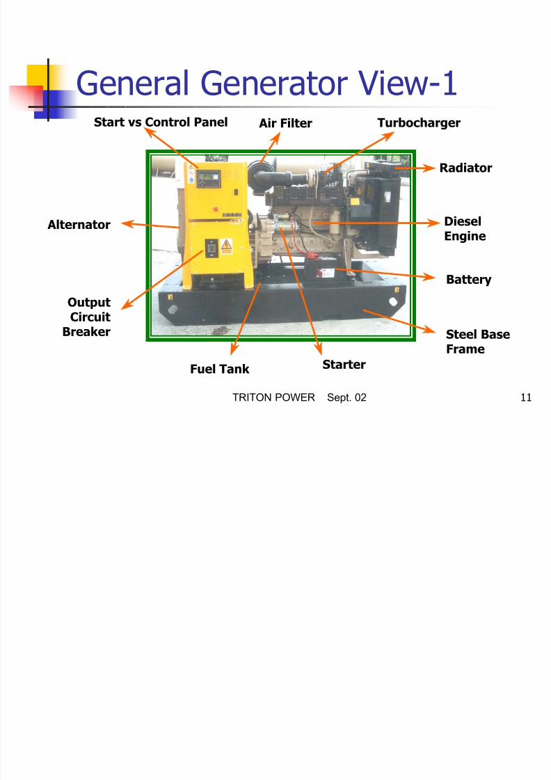
General Generator View-1Start vs Control Panel Turbocharger Air Filter
Radiator
DieselEngine
Alternator
Battery
OutputCircuit
Breaker Steel BaseFrame
StarterFuel Tank

8/16/2019 Installation Recommedations_010902 Ing
http://slidepdf.com/reader/full/installation-recommedations010902-ing 12/97
TRITON POWER Sept. 02 12
General Generator View-2
Lifting BracketEmergency Stop Button
Canopy
Water Proof &
Sound Proof
8/16/2019 Installation Recommedations_010902 Ing
http://slidepdf.com/reader/full/installation-recommedations010902-ing 13/97
TRITON POWER Sept. 02 13
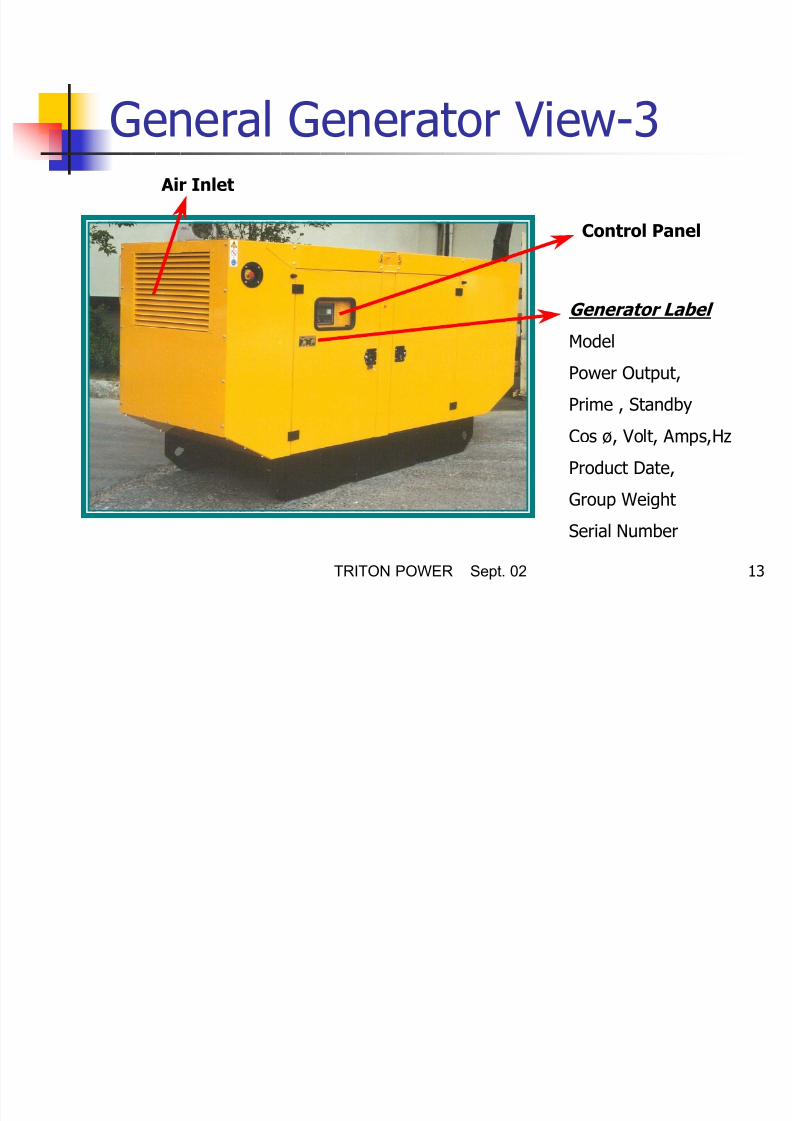
General Generator View-3 Air Inlet
Generator Label
Model
Power Output,
Prime , Standby
Cos ø, Volt, Amps,Hz
Product Date,
Group Weight
Serial Number
Control Panel

8/16/2019 Installation Recommedations_010902 Ing
http://slidepdf.com/reader/full/installation-recommedations010902-ing 14/97
TRITON POWER Sept. 02 14
Diesel Engine The diesel engine powering the
generating set has been choosen for itsreliability and the fact that it has beenspecifially designed for powering sets.
The engine of the heavy duty industrialtype with 4 stroke is compressionignition and fitted with all accessories toprovide a reliable power supply.
These accessories include, among other,a cartridge type air filters and amechanical or an electronic enginespeed governor.
Lenoir Engine
1870

8/16/2019 Installation Recommedations_010902 Ing
http://slidepdf.com/reader/full/installation-recommedations010902-ing 15/97
TRITON POWER Sept. 02 15
Engine Electrical System The engine electrical system is 12
Volts DC if gensets power outputis less than 200 kVA or 24 VoltsDC if gensets power output is
more than 200 kVA. Negative is ground/earth.
This system includes an electricengine starter, a battery and abattery charging alternator.
For 24 Vdc system, two batteriesare given which are connected
series..

8/16/2019 Installation Recommedations_010902 Ing
http://slidepdf.com/reader/full/installation-recommedations010902-ing 16/97
TRITON POWER Sept. 02 16
Cooling System The engine cooling system is
either air cooled or water cooled.
The air cooled system consists ofa high capacity fan to pull cool air
across the engine to cool it. The water cooled system is
comprised of a radiator a pusherfan and thermostat.
The alternator has its owninternal fan to cool the alternatorcomponents and windings.

8/16/2019 Installation Recommedations_010902 Ing
http://slidepdf.com/reader/full/installation-recommedations010902-ing 17/97
TRITON POWER Sept. 02 17
Alternator
The output electrical power is normally produced bya screen protected and drip-proof, self exciting, selfregulating, brushless alternator fine tuned to theoutput of this generating set.

8/16/2019 Installation Recommedations_010902 Ing
http://slidepdf.com/reader/full/installation-recommedations010902-ing 18/97
TRITON POWER Sept. 02 18
Fuel Tank And Baseframe The engine and alternator
are coupled together andmounted on a heavy dutysteel baseframe.
This baseframe includes afuel tank with a capacityof approximately 8 hoursoperation at full load.
(Except for gen-set poweroutput above 710 kVa )
Baseframe Fuel Tank
8/16/2019 Installation Recommedations_010902 Ing
http://slidepdf.com/reader/full/installation-recommedations010902-ing 19/97
TRITON POWER Sept. 02 19
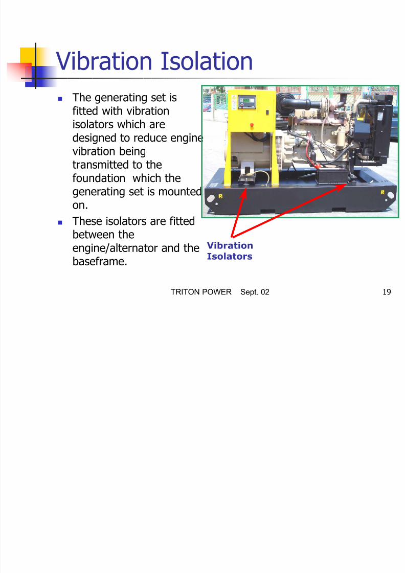
Vibration Isolation The generating set is
fitted with vibrationisolators which aredesigned to reduce enginevibration being
transmitted to thefoundation which thegenerating set is mountedon.
These isolators are fittedbetween theengine/alternator and the
baseframe.
VibrationIsolators

8/16/2019 Installation Recommedations_010902 Ing
http://slidepdf.com/reader/full/installation-recommedations010902-ing 20/97
TRITON POWER Sept. 02 20
Silincer And Exhaust System
An exhaust silencer isprovided loose forinstallation with thegenerating set.
The silencer andexhaust system reducethe noise emission fromthe engine and candirect exhaust gases tosafe outlets.

8/16/2019 Installation Recommedations_010902 Ing
http://slidepdf.com/reader/full/installation-recommedations010902-ing 21/97
TRITON POWER Sept. 02 21
Control System One of several types of control
systems and panels may befitted to control the operation ,output of the set and to
protect the set from possiblemalfunctions.
Control Module

8/16/2019 Installation Recommedations_010902 Ing
http://slidepdf.com/reader/full/installation-recommedations010902-ing 22/97
TRITON POWER Sept. 02 22
Installation,Handling And Storage
General
Once the size of the generating set and anyassociated control systems or switchgear havebeen established, plans for installation can beprepared.

8/16/2019 Installation Recommedations_010902 Ing
http://slidepdf.com/reader/full/installation-recommedations010902-ing 23/97
TRITON POWER Sept. 02 23
Installation,Handling And Storage
Canopies
Installation and handlingis greatly simplified whenthe generating set hasbeen equipped withcanopy.
The canopy also givesprotection from the
elements and protectionfrom unauthorized access.
ASM 5
8/16/2019 Installation Recommedations_010902 Ing
http://slidepdf.com/reader/full/installation-recommedations010902-ing 24/97
TRITON POWER Sept. 02 24
Installation,Handling And Storage
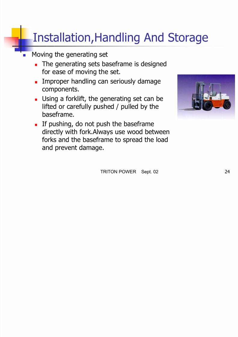
Moving the generating set
The generating sets baseframe is designedfor ease of moving the set.
Improper handling can seriously damagecomponents.
Using a forklift, the generating set can belifted or carefully pushed / pulled by thebaseframe.
If pushing, do not push the baseframedirectly with fork.Always use wood betweenforks and the baseframe to spread the loadand prevent damage.
8/16/2019 Installation Recommedations_010902 Ing
http://slidepdf.com/reader/full/installation-recommedations010902-ing 25/97
TRITON POWER Sept. 02 25
Installation,Handling And Storage
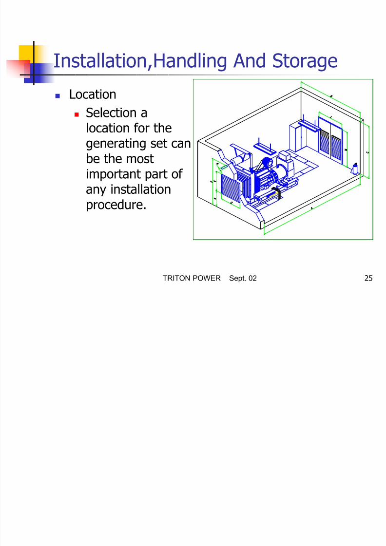
Location
Selection alocation for thegenerating set can
be the mostimportant part ofany installation
procedure.

8/16/2019 Installation Recommedations_010902 Ing
http://slidepdf.com/reader/full/installation-recommedations010902-ing 26/97
TRITON POWER Sept. 02 26
The following factors are important indetermining the location-1
Adequate ventilation
Protection from elements such asrain,snow,sleet,wind drivenprecipitation, flood water, directsunlight, freezing temperatures orexcessive heat.
Protection from exposure toairborne contaminants such asabrasive or conductive dust, lint,smoke, oil mist, vapors, engineexhaust fumes or othercontaminants.
Floor of generating set room mustbe smooth and strong.
Protection from impact from fallingobjects such as trees or poles,orfrom motor vehicles or lift trucks.
8/16/2019 Installation Recommedations_010902 Ing
http://slidepdf.com/reader/full/installation-recommedations010902-ing 27/97
TRITON POWER Sept. 02 27
The following factors are important indetermining the location-2
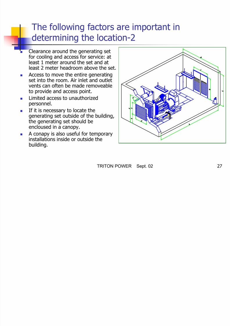
Clearance around the generating setfor cooling and access for service: at
least 1 meter around the set and atleast 2 meter headroom above the set.
Access to move the entire generatingset into the room. Air inlet and outletvents can often be made removeable
to provide and access point. Limited access to unauthorized
personnel.
If it is necessary to locate thegenerating set outside of the building,
the generating set should beencloused in a canopy.
A conapy is also useful for temporaryinstallations inside or outside thebuilding.

8/16/2019 Installation Recommedations_010902 Ing
http://slidepdf.com/reader/full/installation-recommedations010902-ing 28/97
TRITON POWER Sept. 02 28
Foundation’s Vibration Isolation
The generating setis shippedassembled on arigid baseframethat precisely alignsthe alternator andengine and needs
only be bolteddown to a suitableprepared surface.

8/16/2019 Installation Recommedations_010902 Ing
http://slidepdf.com/reader/full/installation-recommedations010902-ing 29/97
TRITON POWER Sept. 02 29
Foundation-1 A reinforced concrete pad provides a rigid support to prevent
deflection and vibration.Typically the foundation should be 150mm to 200 mm (6 to 8”) deep and least as wide and long as thegenerating set.
The ground or floor below the foundation should be properly
prepared and structurally suited to carry the weight of thegenerating set.
If the generating set is installed above the ground floor,thebuilding structure must be able to support the weight of the
generating set, fuel tank and accessories. If the floor may be wet from time to time such as in a boiler
room, the pad should be raised above the floor. This willprovide a dry footing for the generating set and for those who
connect, service or operate it.It will also minimize corrosive action on the baseframe.

8/16/2019 Installation Recommedations_010902 Ing
http://slidepdf.com/reader/full/installation-recommedations010902-ing 30/97
TRITON POWER Sept. 02 30
Foundation-2Start & Control PanelEngine (Diesel,Gas,Gasoline)
Base Frame
a
SmartPower
a
Alternator
1 5 0 - 2 0 0 m m
Foundation

8/16/2019 Installation Recommedations_010902 Ing
http://slidepdf.com/reader/full/installation-recommedations010902-ing 31/97
TRITON POWER Sept. 02 31
Combustion Air Inlet Air for engine combustion must be
clean and as cool aspossible.Normally this air can bedrawn from the area surrounding thegenerating set via the enginemounted air filter.
However, in some cases due to dust,dirt or heat, the air around the set isunsuitable. In these cases an inletduct should be fitted. This ductshould run from the source of cleanair ( outside the building, another
room, etc.) to the engine mounted airfilter. Don’t remove the air filter andmount it at a remote location as thiscan increase the possibility of dirtleaking through the ductwork andinto the engine inlet.

8/16/2019 Installation Recommedations_010902 Ing
http://slidepdf.com/reader/full/installation-recommedations010902-ing 32/97
TRITON POWER Sept. 02 32
Cooling And Ventilation-1 The engine, alternator and exhaust
piping radiate heat which can resultin a temperature high enough toadversely effect the performance ofthe generating set. It is thereforeimportant that adequate ventilation isprovided to keep the engine and
alternator cool. Proper air flow, as shown in figure,
requires that the air comes in at thealternator end of the set, passes overthe engine, through the radiator and
out of the room via a flexible exhaustduct. Without the ducting of the hotair outside the room, the fan will tendto draw that hot air around and backthrough the radiator, reducing thecooling efficiency.

8/16/2019 Installation Recommedations_010902 Ing
http://slidepdf.com/reader/full/installation-recommedations010902-ing 33/97
TRITON POWER Sept. 02 33
Cooling And Ventilation-2 Sharp corners on the
radiator, hot air outletchannel or its chimney mustbe avoided. Somerearrangements to turn
thrown air should be done. The air inlet and outlet
openings should be largeenough to ensure free flow ofair into and out of theroom.As a rough guide theopenings should be each atleast 1.5 times the area ofthe radiator core.

8/16/2019 Installation Recommedations_010902 Ing
http://slidepdf.com/reader/full/installation-recommedations010902-ing 34/97
TRITON POWER Sept. 02 34
Cooling And Ventilation-3 Both the inlet and outlet
openings should have louvres forweather protection. These maybe fixed but preferably should bemovable in cold climates so thatwhile the generating set is not
operating the louvres can beclosed.This will allow the room tobe kept warm which will assiststarting and load acceptance.
For automatic starting generatingsets if the louvres are movable*they must be automaticallyoperated. They should beprogrammed to openimmediately upon starting theengine.
P t ti i t f t i

8/16/2019 Installation Recommedations_010902 Ing
http://slidepdf.com/reader/full/installation-recommedations010902-ing 35/97
TRITON POWER Sept. 02 35
Protection against frost is as
follows..
Antifreeze /Water Protection Down To(% by volume) (°C)
50/50 -3560/40 -40

8/16/2019 Installation Recommedations_010902 Ing
http://slidepdf.com/reader/full/installation-recommedations010902-ing 36/97
TRITON POWER Sept. 02 36
Boil Point
020
40
60
80100
120
140
160
180
0 1 0
2 0
3 0
4 0
5 0
6 0
7 0
8 0
9 0
1 0 0
Boil Point
B o i l
P o i n t
° C
% Antifreeze

8/16/2019 Installation Recommedations_010902 Ing
http://slidepdf.com/reader/full/installation-recommedations010902-ing 37/97
TRITON POWER Sept. 02 37
Frost Point
-80
-70
-60
-50
-40-30
-20
-10
00 10 20 30 40 50 60 70 80 90 100
Frost Point
% Antifreeze
F r o s
t P o i n t ° C
8/16/2019 Installation Recommedations_010902 Ing
http://slidepdf.com/reader/full/installation-recommedations010902-ing 38/97
TRITON POWER Sept. 02 38
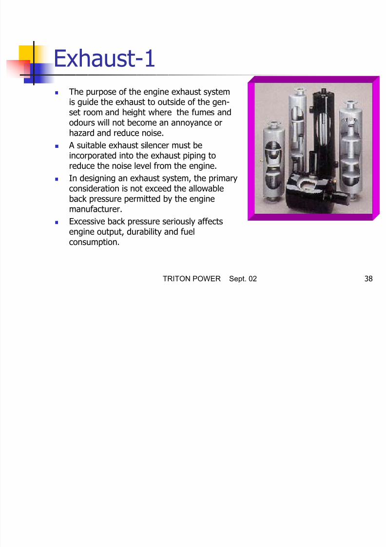
Exhaust-1 The purpose of the engine exhaust system
is guide the exhaust to outside of the gen-set room and height where the fumes andodours will not become an annoyance orhazard and reduce noise.
A suitable exhaust silencer must be
incorporated into the exhaust piping toreduce the noise level from the engine.
In designing an exhaust system, the primaryconsideration is not exceed the allowableback pressure permitted by the engine
manufacturer.
Excessive back pressure seriously affectsengine output, durability and fuelconsumption.

8/16/2019 Installation Recommedations_010902 Ing
http://slidepdf.com/reader/full/installation-recommedations010902-ing 39/97
TRITON POWER Sept. 02 39
Exhaust-2 To limit the exhaust back pressure,
the exhaust piping should be asshort and straight as possible.
Any required bends should have acurve radious of at least 1.5 timesthe inside diameter of the pipe.
A flexible connection between theexhaust manifold and the pipingsystem should be used to preventtransmission of engine vibration tothe piping and the building and to
allow for thermal expansion and anyslight misalignment of the piping.

8/16/2019 Installation Recommedations_010902 Ing
http://slidepdf.com/reader/full/installation-recommedations010902-ing 40/97
TRITON POWER Sept. 02 40
Exhaust-3 The exhaust pipes should be
supported by the building in order
to prevent the dead-weightcarried by the engine manifoldand turbocharger.For that,stretching elements should beused.
Exhaust system componentslocated within the generator roomshould be insulated to reduce heatradiation and noise level.
Pipes and the silencer, whetherlocated inside and outside thebuilding, should be located wellclear of any combustible material.

8/16/2019 Installation Recommedations_010902 Ing
http://slidepdf.com/reader/full/installation-recommedations010902-ing 41/97
TRITON POWER Sept. 02 41
Exhaust-4 The outer end of the exhaust
pipe, if horizontal, should becut at 60° to the horizontalor fitted with a rain hood orcap if vertical to prevent rain
or snow from entering theexhaust system.
The exhaust pipe must notbe connected to other
generating sets exhausts. Exhaust pipes must be made
up black iron pipe.

8/16/2019 Installation Recommedations_010902 Ing
http://slidepdf.com/reader/full/installation-recommedations010902-ing 42/97
TRITON POWER Sept. 02 42
Fuel System The fuel system for the generating set must be capable pf
delivering a clean and continuous supply of fuel to the engine.For most installations, this include a small day tank, a bulkstorage tank and fuel lines.
Do not smoke or allow sparks, flames or other sources of
ignition around fuel. Fuel vapours and oil vapours are explosive.
For systems which have two or more tanks, the tank or tankswhich supply fuel directly to the engine are termed “Day Tanks”
and other tanks in the system, which do not directly supply fuelto the engine, are termed “Bulk Storage or Make-Up Tanks.”

8/16/2019 Installation Recommedations_010902 Ing
http://slidepdf.com/reader/full/installation-recommedations010902-ing 43/97
TRITON POWER Sept. 02 43
Typical Fuel Installation Using a base tank
fed from a bulk tank
1. Fill cabinet withoverfill alarm andgauge
2. Tank fill line
3. Vent
4. Contents gauge
5. Bulk storage tank
6. Sludge drain
7. Bund tank
8. Outlet valve
9. Supply line to daytank
10. Electric fuel transferpump
16. Level gauge
17. Drain18. Leakage alarm
unit (optional)
19. Fuel filter
20. Engine fuel pump
11. Electric fuel shutoff valve
12. Optional band13. Day tank incorporated in
baseframe
14. Float control switches
15. Manual fill and vent

8/16/2019 Installation Recommedations_010902 Ing
http://slidepdf.com/reader/full/installation-recommedations010902-ing 44/97
TRITON POWER Sept. 02 44
Day Tank Day tanks provide a
readily availablesupply of fueldirectly to thegenerating settherefore should belocated within thegenerator room.
The baseframe isdesigned to containa day tank up to 700kVA.
Day tank
8/16/2019 Installation Recommedations_010902 Ing
http://slidepdf.com/reader/full/installation-recommedations010902-ing 45/97
TRITON POWER Sept. 02 45
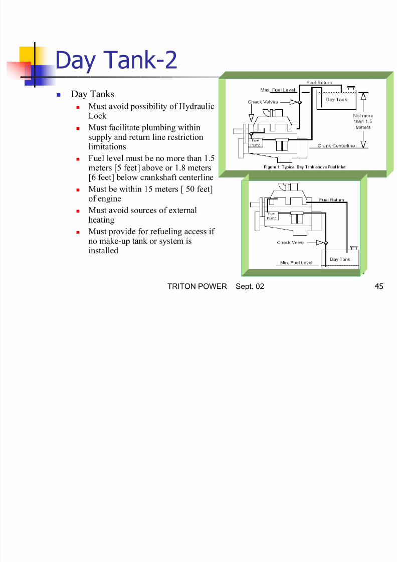
Day Tank-2 Day Tanks
Must avoid possibility of HydraulicLock
Must facilitate plumbing withinsupply and return line restrictionlimitations
Fuel level must be no more than 1.5meters [5 feet] above or 1.8 meters[6 feet] below crankshaft centerline
Must be within 15 meters [ 50 feet]of engine
Must avoid sources of externalheating
Must provide for refueling access if no make-up tank or system isinstalled

8/16/2019 Installation Recommedations_010902 Ing
http://slidepdf.com/reader/full/installation-recommedations010902-ing 46/97
TRITON POWER Sept. 02 46
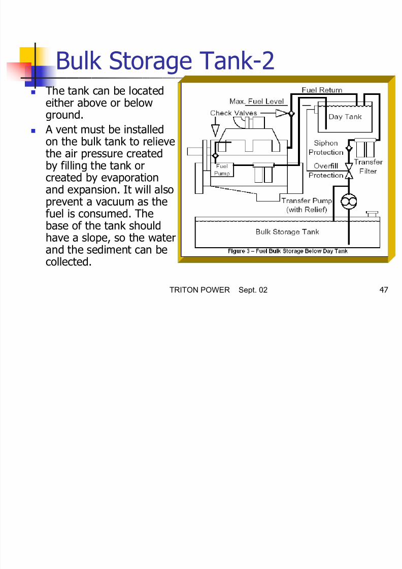
Bulk Storage Tank-1
BulkStorageTank
For extended operation, a separate bulk fuel storage tank isrequired.
The bulk tank should be generally located outside the buildingwhere it will be convenient for refilling, cleaning and inspection.Ifshould not, however, be exposed to freezing weather because fuelflow will be restricted as viscosity increases.
A sludge drain valve should be installed at the low point to allow
removal of water and sediment on a regular basis.
8/16/2019 Installation Recommedations_010902 Ing
http://slidepdf.com/reader/full/installation-recommedations010902-ing 47/97

8/16/2019 Installation Recommedations_010902 Ing
http://slidepdf.com/reader/full/installation-recommedations010902-ing 48/97
TRITON POWER Sept. 02 48
Bulk Storage Tank-2
Must include valves to control and shut off make-up flow
Must include equipment to prevent Day Tank Overfilling
Transfer piping must not be capable of siphoning fuel from day tank
1 8
11 14

8/16/2019 Installation Recommedations_010902 Ing
http://slidepdf.com/reader/full/installation-recommedations010902-ing 49/97
TRITON POWER Sept. 02 49
Tank Materials Must be clean
Must not rust, corrode or contaminate fuel No galvanized steel tanks
An aluminum or protective coated steel (phosphate or terneplate) tank is
common. Galvanized steel tanks or materials that include zinc must notbe used. Fuel can interact with the coating to form oxidized flakes thatcan plug filters and injectors. Interactions between fuel additives andtank materials must also be considered when selecting a tank.
If the fabrication process includes welding, where debris such as slag
could accumulate in the tank, appropriate cleaning after fabrication isrequired.
Tank materials that permit heat in the fuel to be dissipated may reducethe required size of a fuel cooler.

8/16/2019 Installation Recommedations_010902 Ing
http://slidepdf.com/reader/full/installation-recommedations010902-ing 50/97
TRITON POWER Sept. 02 50
Fuel Lines The fuel lines can be any fuel compatible material
such as steel pipe or flexible hoses that will tolerateenvironmental conditions.
Flexible piping should be used to connect to the
engine to avoid damage or leaks caused by enginevibrations.

8/16/2019 Installation Recommedations_010902 Ing
http://slidepdf.com/reader/full/installation-recommedations010902-ing 51/97
TRITON POWER Sept. 02 51
Tank Fittings-1Drain Opening
Must facilitate removal of accumulated water, dirt, etc.
A pipe plug is generally unsatisfactory for this function because of theskill required to remove and reinstall it without releasing excessive
fuel. A drain area that includes a well or settling basin isrecommended because it tends to concentrate the contaminants.Typically the bottom of a fuel tank has rounded corners and slopes ata 2-degree angle toward the drain opening.
17

8/16/2019 Installation Recommedations_010902 Ing
http://slidepdf.com/reader/full/installation-recommedations010902-ing 52/97
TRITON POWER Sept. 02 52
Tank Fittings-2Breather
Must prevent backpressure on fuel return lines Must allow pressure relief while filling or transferring fuel
Must be above the tank’s maximum fuel level
Must be protected from entry of dirt and water Must conform to statutory requirements

8/16/2019 Installation Recommedations_010902 Ing
http://slidepdf.com/reader/full/installation-recommedations010902-ing 53/97
TRITON POWER Sept. 02 53
Tank Fittings-3Fill Opening
Must be above maximum fuel level Fill Neck must provide space for thermal expansion
Cap must be attached to the tank
Must minimize fuel agitation
The fill opening should be large enough to permit the tank to be filled in 2or 3 minutes. The cap should be arranged to prevent mud or dirt fromdropping into the tank when the cap is removed.
A safety or captive chain is recommended for caps that are not otherwiseattached to the tank.
The fill neck should extend into the tank an equivalent of 5 percent of thevolume to provide space for thermal expansion.

8/16/2019 Installation Recommedations_010902 Ing
http://slidepdf.com/reader/full/installation-recommedations010902-ing 54/97
TRITON POWER Sept. 02 54
Tank Fittings-4Fuel Pump Suction Line Connection
Pick up must be at least 25 mm [1 in] above bottom center oftank
Must facilitate required flow rate
Must have a check valve to prevent fuel from draining back to
Day Tank and to prevent flow into cylinders when engine is notrunning.
A bottom outlet fitting may be prone to damage, so a suitable
braced drop tube from the tank top may be preferred. Air leaksin this connection can cause erratic engine behavior, so care inselection and installation is required. A suction screen may be auseful addition if it can be easily accessed for cleaning.
Day Tank to Engine

8/16/2019 Installation Recommedations_010902 Ing
http://slidepdf.com/reader/full/installation-recommedations010902-ing 55/97
TRITON POWER Sept. 02 55
Day Tank to Engine
(Fuel Supply Line) Must have restriction less than or equal to engine data sheet
requirements Must have a check valve to prevent fuel accumulation in
cylinders when engine is stopped
Must avoid sources of external heating
Engine to Day Tank

8/16/2019 Installation Recommedations_010902 Ing
http://slidepdf.com/reader/full/installation-recommedations010902-ing 56/97
TRITON POWER Sept. 02 56
Engine to Day Tank
(Fuel Return Line)
Must have restriction less than or equal to engine data sheetrequirements
Must have a check valve to prevent fuel accumulation incylinders when engine is stopped if this accumulation is possible
via the fuel return lines
Fuel Shut-off devices not permitted at this line
Must avoid sources of external heating

8/16/2019 Installation Recommedations_010902 Ing
http://slidepdf.com/reader/full/installation-recommedations010902-ing 57/97
TRITON POWER Sept. 02 57
Fuel Return Line Connection
Must allow separation of fuel and vapor or gases in theexpansion space above the normal fuel level
Must minimize fuel agitation
If fuel level can be above the level of the crankshaft, a check
valve is required in the fuel return line If Fuel level can be below the level of the crankshaft, the
discharge must be below the lowest fuel level in the day tank.
The return line discharge should be pointed away from thebreather and the suction areas.
Flowing the return against a sidewall or baffle at a shallow anglecan sometimes minimize agitation.

8/16/2019 Installation Recommedations_010902 Ing
http://slidepdf.com/reader/full/installation-recommedations010902-ing 58/97
TRITON POWER Sept. 02 58
Fuel Heating and Cooling-1 Fuel Inlet Temperature must not exceed Engine data sheet requirements
Fuel heaters are required if ambient temperature can be below the fuel cloud point
Power loss can be expected when fuel temperature is greater than 49oC [120oF] (some manufacturer recommended that it is start a power loss when fueltemperature is greater than 40°C)
In general, fuel at temperatures greater than or equal to 71oC [160 oF] shouldnever be supplied to the engine. Since fuel is used to carry away heat on someengine models, fuel cooling may be necessary to keep inlet fuel within the
specified operating range. Duty cycle, size of the day tank, and heat rejectionfor the particular engine are all factors which must be considered when sizinga fuel cooler. Consult the engine data sheet for specific heat rejectionrequirements.

8/16/2019 Installation Recommedations_010902 Ing
http://slidepdf.com/reader/full/installation-recommedations010902-ing 59/97
TRITON POWER Sept. 02 59
Fuel Heating and Cooling-2Fuel coolers should be installed only in the return lines. DO NOT plumb the heat
exchanger in the fuel supply (Day Tank to Engine Fuel Pump) lines. Typicallythe inlet (hot fuel) is lower than the outlet (cooled fuel) to take advantage of
natural convection circulation.
Mount the fuel cooler and all associated wiring and plumbing in a manner that
they are protected from vibration, weather and external sources of heat.Fuel
Coolers may utilize a variety of methods to circulate cooling air through the
heat exchanger, including electric or hydraulic motors or drive belts. If the
engine is equipped with a fan clutch, an alternate means of circulating cooling
air should be considered.

8/16/2019 Installation Recommedations_010902 Ing
http://slidepdf.com/reader/full/installation-recommedations010902-ing 60/97
TRITON POWER Sept. 02 60
Lubrication Oil Oil system of diesel engine is one of the most important
elements of the engines.Correctly made engine overhaul (thissubject includes oil change periods,paying attention aboutselection the true type of oil) prolongs the life of the engineand it decreases the life cycle cost of the engine.
The American Petroleum Institute (API) , The American SocietyFor Testing and Materials (ASTM) and Society Of AutomotiveEngineers (SAE) has developed and preserved a system in orderto classify the lubrication oils for their performance categories.
In oil performance recommendations modifiers, according totheir MIL specifications, has been given in paranthesis.

8/16/2019 Installation Recommedations_010902 Ing
http://slidepdf.com/reader/full/installation-recommedations010902-ing 61/97
TRITON POWER Sept. 02 61
Trade Oil Categories CF-4 (It has no modifier property) and similar oils are being used for four
stroke, high velocity diesel engines. API CF-4 oils contain properties above theCE category oils.These oils can be used for CE oils.
CE (It has no modifier property) oils with their high cover properties as certainprotection against abrasion, low oil consumption and better protection againstprecipitation.These oil have been produced in turbocharge and supercharge type
since 1983 in low speed, high speed and overloading conditions and it has beendesigned as serious service oil in diesel engine applications.
CD-11 (MIL-L-2104D/E) has been chosen for two stroke diesel engines categoryand it has been designed for high service conditions since it necessitates highlevel of control because of the precipitations and abrasions.
CC (MIL-L-21048) type of oil as certain protection from precipitation and CC oilshas been designed to work at high temperatures more easily.

8/16/2019 Installation Recommedations_010902 Ing
http://slidepdf.com/reader/full/installation-recommedations010902-ing 62/97
TRITON POWER Sept. 02 62
Recommended SAE Viscosity Levels
AmbientTemperature
Lubrication Recommendation For

8/16/2019 Installation Recommedations_010902 Ing
http://slidepdf.com/reader/full/installation-recommedations010902-ing 63/97
TRITON POWER Sept. 02 63
Lubrication Recommendation For
Cummins
Cummins recommends that high quality SAE 15W/40
high service engine oil in diesel engines are used. The minimum API oil quality levels recommended for
use is CE or CF-4.CD/SF oil can be used in areaswhere CE or CF-4 oil is not yet available, but the oilchange interval must be reduced to one half theinterval given in the maintenance schedule.
If naturally aspirated engines or turbocharged
engines are being used as excess power (stand-by)CD oil may be used without thinking of the oilchanging periods.
Lubrication Recommendation

8/16/2019 Installation Recommedations_010902 Ing
http://slidepdf.com/reader/full/installation-recommedations010902-ing 64/97
TRITON POWER Sept. 02 64
Lubrication Recommendation
For Perkins
For Perkins engines, good quality lubrication oil should be used
as shown below ;
For naturally aspirated engines API CC/SE,MIL-L-4612
API CC/SE, MIL-L-2104D,ACEA
For naturally aspirated engines working in high service conditions API CC/SE, MIL-L-2104D,CCMC D4 *
For turbocharged engines API CC/SE, MIL-L-2104D,CCMC D4 *
* It is not recommended for light loads and first 25/50 workinghours.
Lubrication Recommendation
8/16/2019 Installation Recommedations_010902 Ing
http://slidepdf.com/reader/full/installation-recommedations010902-ing 65/97
TRITON POWER Sept. 02 65
Lubrication Recommendation
For John Deere
John Deere engine manufacturer recommends the
following lubrication oils API CE or API CD
CCMC D4 or CCMC D5
Lubrication Recommendation

8/16/2019 Installation Recommedations_010902 Ing
http://slidepdf.com/reader/full/installation-recommedations010902-ing 66/97
TRITON POWER Sept. 02 66
Lubrication Recommendation
For Yanmar
To help assist engine running, all engines are
dispatched with an initial fill lubricating oil whichmust be changed after 50 hours.
Yanmar engine manufacturer recommends the
following oils; API CC or CD
Lubrication Recommendation

8/16/2019 Installation Recommedations_010902 Ing
http://slidepdf.com/reader/full/installation-recommedations010902-ing 67/97
TRITON POWER Sept. 02 67
Lubrication Recommendation
For Lister Petter
To help assist engine running, all engines are
dispatched with an initial fill lubricating oilwhich must be changed after 100 hours.
Lister Petter engine manufacturer
recommends the following oils; API CC
DEF 2101 D MIL-L-46152 B
MIL-L-2104 B
Lubrication Recommendation

8/16/2019 Installation Recommedations_010902 Ing
http://slidepdf.com/reader/full/installation-recommedations010902-ing 68/97
TRITON POWER Sept. 02 68
For Deutz
Deutz engine manufacturer recommends the
following oils; API CF-4,CG-4,CH-4
ACEA E1-E3-96 + E4 -98
8/16/2019 Installation Recommedations_010902 Ing
http://slidepdf.com/reader/full/installation-recommedations010902-ing 69/97
Lubrication Recommendation

8/16/2019 Installation Recommedations_010902 Ing
http://slidepdf.com/reader/full/installation-recommedations010902-ing 70/97
TRITON POWER Sept. 02 70
For MTU
MTU engine manufacturer recommends the following
oils for 2000 and 4000 series engines; API CG-4
ACEA E2-96
ACEA E3-96
8/16/2019 Installation Recommedations_010902 Ing
http://slidepdf.com/reader/full/installation-recommedations010902-ing 71/97
TRITON POWER Sept. 02 71
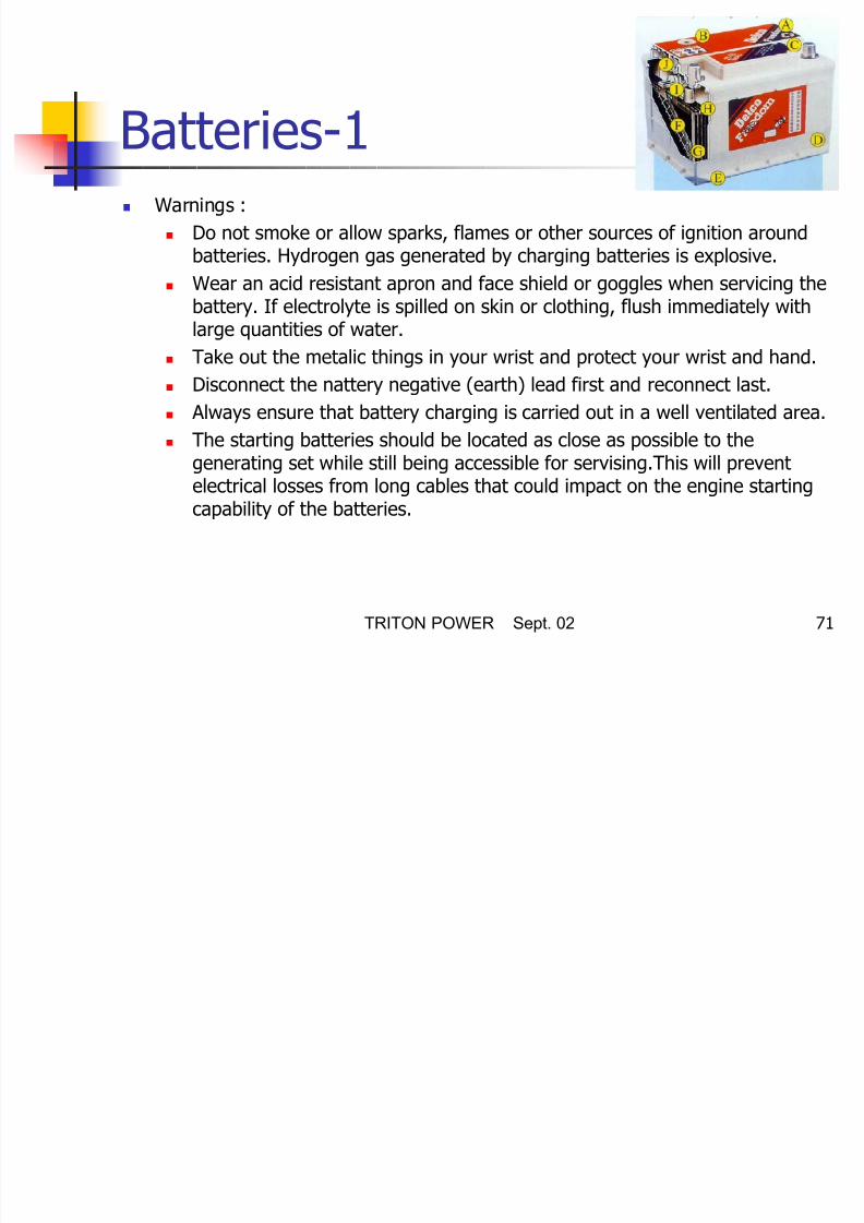
Batteries-1 Warnings :
Do not smoke or allow sparks, flames or other sources of ignition aroundbatteries. Hydrogen gas generated by charging batteries is explosive.
Wear an acid resistant apron and face shield or goggles when servicing thebattery. If electrolyte is spilled on skin or clothing, flush immediately withlarge quantities of water.
Take out the metalic things in your wrist and protect your wrist and hand. Disconnect the nattery negative (earth) lead first and reconnect last.
Always ensure that battery charging is carried out in a well ventilated area.
The starting batteries should be located as close as possible to the
generating set while still being accessible for servising.This will preventelectrical losses from long cables that could impact on the engine startingcapability of the batteries.

8/16/2019 Installation Recommedations_010902 Ing
http://slidepdf.com/reader/full/installation-recommedations010902-ing 72/97
TRITON POWER Sept. 02 72
Batteries-2 First filling of acid water to the battery
Take out the protective cover above the taps and tear down the air outlet
taps. Fill the battery with a clean accumulator acid having a density of 1280 at
20°C until the point 15 mm above plates.Battery and acid temperature mustabove 10°C.
Let the battery to stand still 15 minutes. After that point battery pockets will
start to become heated and gas bubbles will rise at the surface ofelectrolyte.
Attach the air outlet taps to their place.
After waiting at least 15 min. Control the battery with a hydrometer.
Minumum charge time is 6 hours.
If the charge voltage and electrolyte level does not increase in at leastone hour period that means battery has been charged.
Control the electrolyte level after two hours from the charge and ifnecessary add distilled water so that it is 10 mm. Above plates.

8/16/2019 Installation Recommedations_010902 Ing
http://slidepdf.com/reader/full/installation-recommedations010902-ing 73/97
TRITON POWER Sept. 02 73
Batteries-3 Batteries Maintenance
Keep the top of the battery and its teminals clean Cover the cattery teminals and its connections with vaseline.
Tighten the teminals but not tighten it hardly.
Control the electrolyte level periodically. It must be 10mmabove the plates.
Control the abrasion in the charge alternator belt and checkperiodically the belt tension according to the producer’s
recommendation. Ensure that your battery in not uncharged.

8/16/2019 Installation Recommedations_010902 Ing
http://slidepdf.com/reader/full/installation-recommedations010902-ing 74/97
TRITON POWER Sept. 02 74
Batteries-4 Testing the batteries
Conduct an inspection every time before testingthe battery.
A white powdered element causes abrasion to
the pole-heads, its surroundings and theconnections. Remove the connections andwash them with hot water to purify the
oxidation. Reconnect it and coat with vaseline. Check if any untightened connections exist.

8/16/2019 Installation Recommedations_010902 Ing
http://slidepdf.com/reader/full/installation-recommedations010902-ing 75/97
TRITON POWER Sept. 02 75
Batteries-5 Hydometer Test
Sulphuric acid density and its charge situation hasbeen determined by using a hydrometer. Do not add distilled water
Keep the barrel part of the equipment in the verticalposition and pull on the sufficient amount of electrolyte.Inside the tube there must be a free float and it shouldbe readable at the eye level.
Evaluation is as the following ;
Between 1.270 and 1.280 density level is fully charged
Between 1.220 and 1.230 density level is half charged
Between 1.150 and 1.220 density level is low charged.

8/16/2019 Installation Recommedations_010902 Ing
http://slidepdf.com/reader/full/installation-recommedations010902-ing 76/97
TRITON POWER Sept. 02 76
Batteries-6 Free Maintenance Batteries
Ensure that all battery connections arecorrect and batteries are always changed.
After that there is not any maintenanceprocedure for this batteries.

8/16/2019 Installation Recommedations_010902 Ing
http://slidepdf.com/reader/full/installation-recommedations010902-ing 77/97
TRITON POWER Sept. 02 77
Electrical Connections-1 Cabling
Due to movement of generating sets on their vibrationmounts, the electrical connections to the set should be madewith flexible cable.
The cable should be protected by laying it in a duct or cable
tray The cable must be suitable for the output voltage of the
gen-set and rated of the set. In determining the size,allowances should be made for ambient temperature,methodof installation, proximity of other cables, etc.
All connections should be carefully checked for integrity.

8/16/2019 Installation Recommedations_010902 Ing
http://slidepdf.com/reader/full/installation-recommedations010902-ing 78/97
TRITON POWER Sept. 02 78
Electrical Connections-2 Cable cross section selections
If the distance between load and generator is too length, voltage falling
at the load side can be too much at the transient current duration.
In this case you should calculate the cable cross sections with electricalformule which has been given below;
( )
(ohm/m)cableof Resistance:
(ohm/m)cableof Resistance:
Current:
(meter)lengthCable:
fallingVoltage:
3
X
R
I
L
e
XSin RCos I Le φφ +×××=

8/16/2019 Installation Recommedations_010902 Ing
http://slidepdf.com/reader/full/installation-recommedations010902-ing 79/97
TRITON POWER Sept. 02 79
Electrical Connections-3 Loading
When planning the electrical distribution system, it is importantto ensure that a balanced load is presented to the generatingset.If loading on one phase is substantially higher than the otherphases, it will cause overheating in the alternator windings,imbulance in the phase to phase output voltage and possible
damage to sensitive 3 phase equipment which is connected tothe system.
Ensure that no individual phase current exceeds the currentrating of the generating set.
For connection to an existing distribution system, it may benecessary to reorganize the distribution system to ensure theseloading factors are met.

8/16/2019 Installation Recommedations_010902 Ing
http://slidepdf.com/reader/full/installation-recommedations010902-ing 80/97
TRITON POWER Sept. 02 80
Electrical Connections-4 Power Factor
The power factor (Cos ø) of the connected load should bedetermined. Power factor below 0,8 lagging (inductive) canoverload the generator. The set will provide its kilowattrating and operate satisfactorily from 0,8 lagging to unity
power factor (1,0). Particular attention must be given to installations with power
factor correction equipment such as capacitors to ensurethat a leading power factor is never present.This will lead to
voltage instability and may result in damaging overvoltages.
Generally whenever the generating set is supplying the loadany power factor correction equipment should be switch off.

8/16/2019 Installation Recommedations_010902 Ing
http://slidepdf.com/reader/full/installation-recommedations010902-ing 81/97
TRITON POWER Sept. 02 81
Engine Jacket Water Heater Heater warms up the jacket
water of the engine whenthe generating set is notworking.
Jacket water heater is usedin order to start up thegenerating set more easilyand take the load. In
automatic generating sets jacket water heater isstandard. In manual type gen-sets it is an option.
Hot outletCold inlet

8/16/2019 Installation Recommedations_010902 Ing
http://slidepdf.com/reader/full/installation-recommedations010902-ing 82/97
TRITON POWER Sept. 02 82
Towing (Portable Gen-Sets) Inspect tyres for condition and proper inflation.
Check that all tail lights are operating properly andthat all reflectors are clean and functional.
Whenever towing a mobile generating set, remember
that manoeuvrabilty and stopping distance will beaffected by the weight of the trailer.
Do not permit personnel to ride on the mobile set. Do
not permit personal to stand or ride on the drawbaror to stand or walk between gen-set and towingvehicle.

8/16/2019 Installation Recommedations_010902 Ing
http://slidepdf.com/reader/full/installation-recommedations010902-ing 83/97
TRITON POWER Sept. 02 83
Gen-Set Control Systems To control And monitor the generating set, an
electronic control system has been used. Depending on the requirement of the set,one of
several different different standart control systems
may be fitted. Control panel provides a means of starting and
stopping the gen-set, monitoring its operation and
output, and automatically shutting down the set inthe event of a critical condition arising such as lowoil pressure or high engine temperature.

8/16/2019 Installation Recommedations_010902 Ing
http://slidepdf.com/reader/full/installation-recommedations010902-ing 84/97
TRITON POWER Sept. 02 84
Panel Equipments Before starting or running
the generating set, theoperator should becomefully acquainted with theinstruments and controls.
The instruments should beobserved from time to timewhile the generating set is
running so that anyabnormal readings can bedetected before problemsarise.

8/16/2019 Installation Recommedations_010902 Ing
http://slidepdf.com/reader/full/installation-recommedations010902-ing 85/97
TRITON POWER Sept. 02 85
AC Voltmeter A voltmeter that indicates
the AC voltage generated atthe alternator outputterminals.
The reading indicated on thevoltmeter will vary
depending on theconnections made inside thealternator terminal box, thesetting of the voltage
regulator and the position ofthe voltage regulator and theposition of the voltmeterselector switch.

8/16/2019 Installation Recommedations_010902 Ing
http://slidepdf.com/reader/full/installation-recommedations010902-ing 86/97
TRITON POWER Sept. 02 86
Voltmeter Selector Switch A selector switch is
allowing theoperator to selectvoltage reading
between phases orbetween a phaseand neutral.

8/16/2019 Installation Recommedations_010902 Ing
http://slidepdf.com/reader/full/installation-recommedations010902-ing 87/97
TRITON POWER Sept. 02 87
AC Ampermeter An ammeter that
indicates the ACelectrical currentbeing delivered
which isdependent onthe connected
load. There arethree ammeterfor each phase.
F M (H )

8/16/2019 Installation Recommedations_010902 Ing
http://slidepdf.com/reader/full/installation-recommedations010902-ing 88/97
TRITON POWER Sept. 02 88
Frequency Meter (Hz) A meter that indicates the output
frequency of the generating set. The
engine maintains a relatively constantspeed under governor control so asto provide the proper operatingfrequency of 50 Hz or 60 Hz whenthe generating set is operating at full
load.
In practice, if the generating set hasa manual governor control system, noload frequencies of approximately 52Hz or 62 Hz for 50 Hz and 60 Hzrespecttively, are considered.
The frequencies will fall to 50 Hz and60 Hz at full load as the set is loaded.
H R M t
8/16/2019 Installation Recommedations_010902 Ing
http://slidepdf.com/reader/full/installation-recommedations010902-ing 89/97
TRITON POWER Sept. 02 89
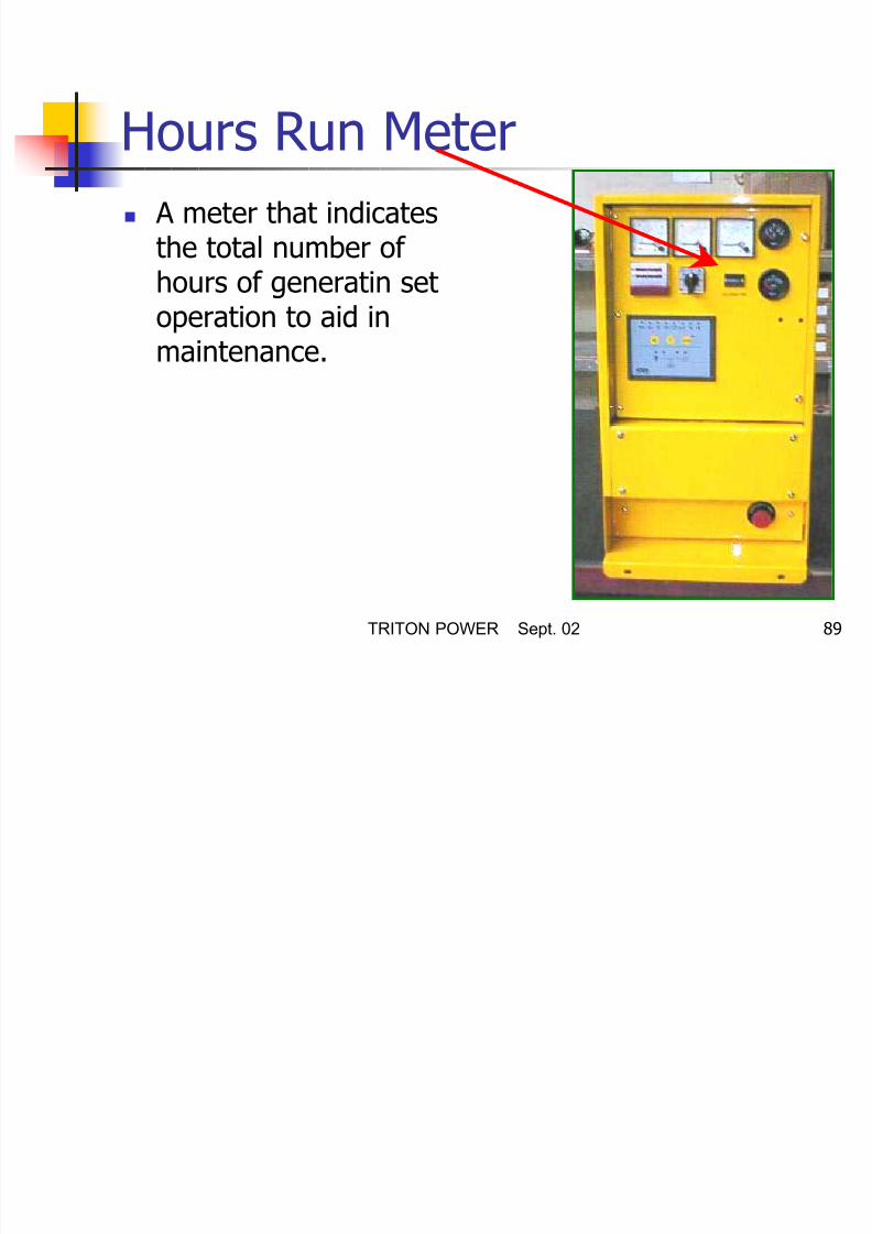
Hours Run Meter A meter that indicates
the total number ofhours of generatin setoperation to aid in
maintenance.
W t T t G

8/16/2019 Installation Recommedations_010902 Ing
http://slidepdf.com/reader/full/installation-recommedations010902-ing 90/97
TRITON POWER Sept. 02 90
Water Temperature Gauge A temperature gauge
connected to asensor in the engineto monitor engine
coolant temperature. Normal level of the
engine coolanttemperature isapproximately 85°C.(185°F)
Oil P G

8/16/2019 Installation Recommedations_010902 Ing
http://slidepdf.com/reader/full/installation-recommedations010902-ing 91/97
TRITON POWER Sept. 02 91
Oil Pressure Gauge A gauge to monitor
engine oil pressure. On cold engines the
oil pressure will be
significiantly higheruntil the enginewarms up.
E St P hb tt

8/16/2019 Installation Recommedations_010902 Ing
http://slidepdf.com/reader/full/installation-recommedations010902-ing 92/97
TRITON POWER Sept. 02 92
Emergency Stop Pushbutton A red lockdown push
button thatimmediately shutsdown the generating
set and will inhibitstart until thepushbutton has beenreleased by turning it.
B tt Ch L

8/16/2019 Installation Recommedations_010902 Ing
http://slidepdf.com/reader/full/installation-recommedations010902-ing 93/97
TRITON POWER Sept. 02 93
Battery Charge Lamp In generating sets without
a charge alternator whenthe battery charge lamp ison,this indicates that thebattery charger is working.
This means that the batteryis being charged.
In generating sets with acharge alternator when the
battery charge lamp is on,it incidates that there is afault in the chargingprocess.
Alt t P t ti

8/16/2019 Installation Recommedations_010902 Ing
http://slidepdf.com/reader/full/installation-recommedations010902-ing 94/97
TRITON POWER Sept. 02 94
Alternator Protection In our standart production,
the alternators in automaticoperation generating sets areprotected with a thermicprotector against overload.
In our standart production ofmanual operated generatingsets, the alternators areprotected against overload
and short circuit by a thermicmagnetic switch.
The Placement And Installation Of
Transfer Switch 1

8/16/2019 Installation Recommedations_010902 Ing
http://slidepdf.com/reader/full/installation-recommedations010902-ing 95/97
TRITON POWER Sept. 02 95
Transfer Switch-1 Position the transfer switch near the emergency power panel
Locate the transfer switch in a place where it is clean, not over-heated,
and having a good ventilation. If the ambiant temperature is above 40°C, fuses and breakers will
open more easily.
There must be enough working place around the transfer switch.
Currents from the generating set must be distributed equally to the 3phase if possible. Current from one phase should not exceed thenominal current.
If the transfer switch panel is apart from the generating set, transferswitch must be placed as close as possible to the distrubutor panel. Inthis case power cables are drawn from generating set, mains panel andemergency power panel. Furthermore 8x2.5 mm² control cable mustbe drawn from the generating set control panel.
The Placement And Installation Of
Transfer Switch 2

8/16/2019 Installation Recommedations_010902 Ing
http://slidepdf.com/reader/full/installation-recommedations010902-ing 96/97
TRITON POWER Sept. 02 96
Transfer Switch-2
G
kWh
Troubleshooting

8/16/2019 Installation Recommedations_010902 Ing
http://slidepdf.com/reader/full/installation-recommedations010902-ing 97/97
TRITON POWER Sept. 02 97
Troubleshooting Alternator troubleshooting
Diesel engine troubleshooting