installation references - tcbm
TRANSCRIPT

1
INSTALLATION REFERENCES R E S y S TA C P 1 2 0 6 1 2 / C P 1 2 0 4 1 2
Version 1 / March 2012 / North America
• no swelling• no cracking• no splintering• no rotting
25 YEARS WARRANTY

2

3
1. Basics
2. Product Range
3. General Information
4. Pre-Treatment
5. Installation Instructions
6. Assembly
7. Important Information
8. Technical Data

4 BASICS
1. Basics
a The dimensional change of Resysta is solely dependent on the thermal expansion.
Air humidity and water have no influence on dimensional change. Thermal expansion
has to be considered at installation.
B Cutting to length should be carried out at consistent material temperature. Therefore,
the material should be stored in the shade or in areas where it is not exposed to direct
sunlight. The material can warm up considerably in the sun, leading to an increased
change in length. In the case of more distinct fluctuations in material temperature,
cutting to length may have to be adapted accordingly.
C Resysta has a high vapor diffusion resistance. Please consider at installation.
D Resysta has a class A fire rating (ASTM-E84).
E Cut-off pieces and/or abrasive dust have to be disposed separately. Please comply with
regulations of your competent waste management. you may under no circumstances
burn Resysta yourself.
Material Temperature 30F 65F 100F Abbuting Gap
Profil 12’ 3/8“ 1/4“ 1/16“ 3/8“

5BASICS
Wood Preservation – Properties in Comparison to WoodIn comparison to wood, and owing to the material properties, the following
does not apply to Resysta:
• discoloring of the surface due to chemical decomposition and wash off of
wood components.
• resin discharge
• surface erosion
• crack formation due to expansion and shrinking
• ingress of moisture (water)
• dishing due to varying moisture spreading
• capillary action at frontal area
Resysta is an innovative material consisting of polymers and rice husks and does
not possess typical wood characteristics like graying, cracking and splintering.
Owing to the special properties of Resysta the basic installation technique merely
differs in some aspects from the installation of other products.
StoragE• please store Resysta products horizontally on level surfaces
• the profiles should never be covered with plastic foil or the like – no matter if already
mounted or not. Condensation and accumulated water can cause staining.

6
* Additional profiles are available, which can, for example, be used as runners
or end pieces.
RESCP120612
materialcolor width x heightx depth
Resystanatural1/2“ x 6“ x 12‘
RESCP120412
materialcolor width x heightx depth
Resystanatural1/2“ x 4“ x 12‘
2. Product Range *
PRODUCT RANGE
7
3. General Information
Standard woodworking tools can be used for the processing of the material.
the assembly should be carried out by a skilled specialist.
SaWINg: Resysta may be cut longitudinal and transversal with all customary saws.
MILLINg: Any profiles can be milled easily by means of customary woodworking
machines.
SaNDINg: Resysta should be grinded in longitudinal direction only.
Depending on the required surface structure, we recommend the use of sand paper with
graining between 24 and 60. Fine-grit sand paper should only be employed
for the removal of dirt.
DrILLINg: Drilling can also be done with customary standard wood drills.
Finishing/Staining Resysta can be treated with Resysta stains. you will find especially developed and
carefully matched color shades in the Resysta Color Concept. It is recommended to use
the colors and sealer especially developed for Resysta.
Cleaning and Care Resysta is extremely easy to maintain. Please refer to cleaning and maintenance details
specified in the separate information sheet or at www.resysta.com.
Bonding Resysta International GmbH offers adhesives and bonding agents for the bonding
of surface profiles with floor, wall and ceiling. Resysta may be glued with standard
PU-adhesive or a suitable plastic adhesive.
GENERAL INFORMATION

8
4. Pre-Treatmentapplication of the color-stain (FVg)
application of the sealant (rFS)
To obtain a uniform and optimal color result, the stain should be applied at consistent
basic conditions.
We therefore recommend applying the stain before installation on each profile individu-
ally. Application temperature approx. 40° - 80°F, relative air humidity approx. 50 – 60%.
To achieve increased protection against soiling and weathering we generally recommend
application of the sealer. The colorless sealer may be applied to Resysta untreated and
Resysta stained material. For further details please refer to data sheet ‘stains and sealers’
at www.resysta.com.
Surface treatment resysta Reasons for recommended surface treatment of Resysta:
• color scheme
• protection against soiling
• protection against fading of color
PRE-TREATMENT

9
1. rear Ventilation
5. Installation Instructions
Due to Resysta’s high diffusion resistance, a rear ventilation
of the facade is always required. The rear ventilation space
must consistently measure at least 3/4“ and may not
be narrowed.
The distance must consistently be at least 3/4“ wide.
2. Center Distance
RESCP120612
RESCP120412
16“
16“
MaXIMUM SPaNrESySta ProFILE
INSTALLATION INSTRUCTIONS

10
5. Installation Instructions3. Spacing
The expansion joint should measure 3/8“ with frontal
profile joints.
When connected to another building,
an expansion joint of 3/8“ is required.
3/8“
3/8“
The distance from profile end to the screw connection may
measure a maximum of 2“.
The distance from screw to profile edge must measure
at least 5/8“.
5/8“
5/8“
2“
INSTALLATION INSTRUCTIONS
11
5. Installation Instructions4. EdgesIngress of moisture at the edges cannot occur. To improve color adherence,
we recommend rounding off sharp edges and cutting edges prior to color treatment with
80 – 100 grid sand paper.
5. Frontal area protection
6. Driving rain protection
7. Splash water protection
Resysta does not feature capillary action. Therefore, a frontal area protection with color
is not strictly necessary. Paint coating may however be done for visual reasons.
Thanks to the high material density no adverse effects are caused by driving rain.
Thanks to the high durability (resistance) of Resysta a material impairment does not
occur. Increased soiling can be expected and can result in staining. We recommend trea-
ting Resyta with sealer (RFS) in the affected area. It is absolutely required to protect
the substructure against ingress of moisture.
INSTALLATION INSTRUCTIONS

12
6. Assembly6.1. SubstructureThe substructure has to be designed according to professional carpentry requirements.
The dead load and the high diffusion resistance of Resysta has to be taken into
consideration. Fastening of the facade is generally carried out on a wooden substructure.
Please attend to the following guidelines for substructures:
• wood must correspond to sort-classification S10 according to DIN 4074
• individual cross-section must be chosen according to DIN 1052
• wood has to be preserved according to DIN 68800 – wood preservation in building
construction
• wooden battening and joists have to be screwed diagonally with 2 screws (A2)
at the cross-over point
• fixation with fasteners approved by building authorities and according to manufacturer
specifications
• the substructure has to be adjusted in alignment and perpendicular orientation
For the substructure, Resysta International GmbH provides special profiles, which may
also be employed. For more details please refer to www.resysta.com.
We explicitly recommend the use of the Resysta substructures because of their durability
and water resistance.
ASSEMBLy

13
6. Assembly
The support battening can be installed vertically or horizontally. The following spacing
has to be considered prior to support assembly.
the following distances have to be considered for support battening workmanship:
• maximum support span of RESCP120612 and RESCP120412: 16“
• spacing frontal or to another building structure: 3/8“
• maximum excess end: 2“
vertical support battening = installation CP horizontal
horizontal support battening = installation CP vertical
ASSEMBLy

14
6. Assembly
6.4. Fixing the closing profile
6.3. Fixing the next profiles
6.2. Fixing the first profileUses an aluminum J metal to fasten the bottom of the first board
or screw fasten it at the bottom of the board and in the groove.
Always cut 1 inch long slots with a biscuit joiner as shown in the
images. Fasten screw in the middle of the holes and allow the
boards to expand and contract when tightening the screws.
Insert further profiles in the previous one and screw fasten
these in the grooves. Always cut 1 inch long slots with a biscuit
joiner as shown in the images. Fasten screw in the middle
of the holes and allow the boards to expand and contract when
tightening the screws.
If necessary, cut the closing profile to the correct width and
screw connect at the edges. Always cut 1 inch long slots as
shown in the images. Fasten screw in the middle of the holes
and allow the boards to expand and contract when tightening
the screws.
ASSEMBLy
IMPortaNt FIXINg INForMatIoN! To allow expansion and
contraction of the RESCP120612/RESCP120412 boards,
cut 1 inch long slots with a biscuit joiner wherever you screw
fasten the boards. Place the screw in the middle of the hole
and allow the boards to expand and contract when tightening
the screws.
15
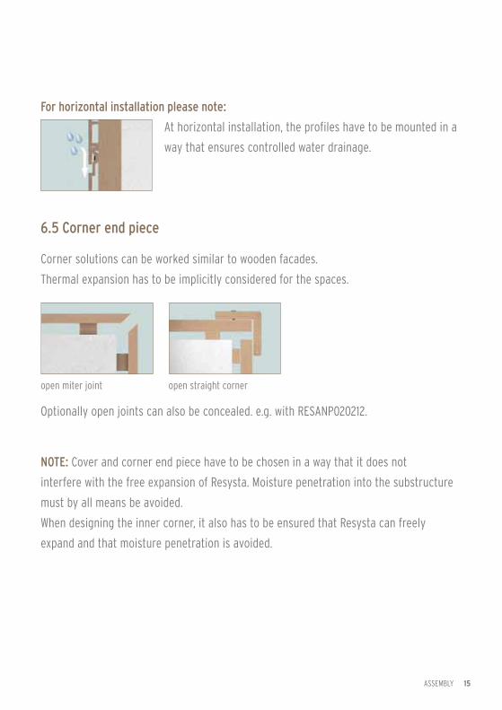
For horizontal installation please note:
6.5 Corner end piece
Corner solutions can be worked similar to wooden facades.
Thermal expansion has to be implicitly considered for the spaces.
At horizontal installation, the profiles have to be mounted in a
way that ensures controlled water drainage.
Optionally open joints can also be concealed. e.g. with RESANP020212.
NotE: Cover and corner end piece have to be chosen in a way that it does not
interfere with the free expansion of Resysta. Moisture penetration into the substructure
must by all means be avoided.
When designing the inner corner, it also has to be ensured that Resysta can freely
expand and that moisture penetration is avoided.
open miter joint open straight corner
ASSEMBLy

16
6. Assembly6.6. Lateral end piece
recessed end piece
overlaying end piece
consider joint distances at lateral
end pieces
ASSEMBLy

17
6.7. Joining
Connections can also be carried out with various Resysta
profiles, for instance apron walls with RESIN5812.
When designing the connections, thermal expansion of Resysta
has to be taken into account.
Joining to roof frames, window lintels, window reveals, apron walls etc., has to be
carried out in a manner that avoids ingress of water into the substructure and allows
for controlled water drainage. In this regard the use of aluminum Z-profiles is
recommended.
ASSEMBLy

18
7. Important Information
!resysta is a new construction material. Basic constructions, fixing material,
etc. have to be conducted in accordance with the general state of technical
knowledge and adjusted to the respective application area and purpose.
!Check material quality prior to installation.
In case of complaints the material may not be installed.
!Please adhere to all current standards and regulations as well as VoB.
!Illustrations in this guideline are no mechanical drawings and display no
technical solutions.
IMPORTANT INFORMATION

19
8. Technical Data
TECHNICAL DATA
Density ASTM D2395:2002 approx. 1.46 kg/m3
Coefficient of Linear Thermal Expansion
ASTM D696 3.6x10(-5)mC
Water Absorption and Air Humidity Behaviour
ASTM D1037:2006a none or very low water absorpti-on (only surface wetting)
Weathering and UV Resistance QUV Test Resysta surfaces treated with glaze show extremely high resistance
Skid Resistance DIN 51097 C Rating (highest rating)
Fire Behaviour (German Standard)
EN ISO 11925-2 B2, normal flammability (by adding flame retardants, a higher rating of B1 can be reached)
Fire Behaviour (US Standard)
ASTM E84 A Rating (flame propagation 25, smoke emission 450)
Fire Behaviour (British Standard) BS 476 Part 6&7 Rating 1
Durability (Resistance to Wood-Destructive Fungi)
DINV ENV 12038:2002 the material has not been affec-ted, highest durability – Class 1
Emission DIN EB ISO 9001/14001 passed
Brinell Hardness (HB) EN 1534 81,1 N/mm2
Friction Coefficient µ untreated EN 13893 0,46
Friction Coefficient µ with 2K EN 13894 0,52
Screw Withdrawal Resistance EN 320.2011-07 5777 N

The Future Formula Is Called Resysta
www.resysta.com
All specifications provided are subject to our installation guidelines and appropriate use at outdoor exposure.
The installation guide may be adapted to technical progress without prior notice.
A download link for the current version is available at www.resysta.com.
Subject to alteration. Slight deviations in color, photos and graphics could occur due to printing process.
commodities used:
approx. 60% rice husks + approx. 22% rock salt + approx. 18% mineral oil = Resysta