installation & service instructions kingfisher...
TRANSCRIPT

About the Boiler See inside cover for models covered by these instructions.This Floor Mounted Fan Assisted Gas Boiler is available as Conventional or Balanced Flue.This boiler is for use with Natural Gas (G20) only at 20mbar and for use in GB & IE.
About Safety The Gas Safety (Installation and Use) Regulations 1998.
‘‘ In your own interest, and that of safety, it is law that all gas appliances are installed by competentpersons, in accordance with the above regulations. Failure to install appliances correctly couldlead to prosecution.’’
Installation must be in accordance with the Installation & Service Instructions and the rules inforce.
Leave these instructions and the Benchmark Log Book with the user for use on future calls.
Installation & Service Instructions Kingfisher MfRSL40 - 100, CFL40 -100
CO
N00
05A
TM
The code of practice for the installation,commissioning & servicing of central heating systems

Publication No. 51029772
Flame Lock-out Re-set
0
Control Panel Serial Number Badge
CO
N00
92B
Data Badge50 -100
Data Badge40
Contents
Contents
Technical Data........................................................3
Introduction..................................................................5Health & Safety Information............................................5Codes of Practice...........................................................5
1. Installation Requirements................................61.1 Gas Supply.......................................................61.2 Electricity Supply..............................................61.3 Location of Boiler..............................................61.4 Air Supply - CFL/RSL..................................7/91.5 Flue Systems - CFL/RSL.............................8/91.6 The System...................................................11
2. Installation...................................................152.1 Install the Boiler...............................................152.2 Install the Flue CFL.........................................15
Install the Flue RSL........................................172.3 Connect the Gas Supply.................................192.4 Connect the Water Supply..............................192.5 Connect the Power Supply Cable.....................202.6 Install the Optional Programmer......................21
3. Commissioning............................................223.1 Commission the Boiler....................................233.2 Final Adjustments..........................................233.3 Instruct the User.............................................243.4 Advise the User..............................................24
4. Service & Replacement of Parts......................254.1 General Access.............................................264.2 Electronic Control Board..................................274.3 Air Pressure Switch........................................274.4 Temperature Sensor.......................................274.5 Overheat Thermostat......................................274.6 Burner, Gas Valve, Injector &
Electrode...................................................284.7 Combustion Chamber Insulation......................294.8 Fan & Flue Hood.............................................294.9 Products Discharge Safety Device
- TTB (CFL Models Only).................................295. Wiring Diagrams..............................................306. Fault Finding....................................................327. Short List of Spares.........................................368. Flue Kits & Optional Extras...............................38
The boiler model and serial number are givenon the boiler data label which is located on theheat exchanger cover plate.
The models covered by these instructions are:-Kingfisher Mf CFL 40 - G.C. No. 41 590 24Kingfisher Mf CFL 50 - G.C. No. 41 590 28Kingfisher Mf CFL 60 - G.C. No. 41 590 29Kingfisher Mf CFL 70 - G.C. No. 41 590 30Kingfisher Mf CFL 80 - G.C. No. 41 590 31Kingfisher Mf CFL 90 - G.C. No. 41 590 32Kingfisher Mf CFL 100 - G.C. No. 41 590 34
Kingfisher Mf RSL 40 - G.C. No. 41 590 35Kingfisher Mf RSL 50 - G.C. No. 41 590 36Kingfisher Mf RSL 60 - G.C. No. 41 590 37Kingfisher Mf RSL 70 - G.C. No. 41 590 38Kingfisher Mf RSL 80 - G.C. No. 41 590 39Kingfisher Mf RSL 90 - G.C. No. 41 590 40Kingfisher Mf RSL 100 - G.C. No. 41 590 41
SAFETY, PERFORMANCE & QUALITYKingfisher Mf boilers have been assessed by a
Government appointed Notified Body and shown tomeet the 'Essential Requirements' of the European
Gas Appliance Directive.
The Directive lays down requirements for the safetyand efficiency of the appliance, together with its
design, construction, and use of materials.It also requires the production process to be covered
by an approved and monitored system of qualityassurance.
Fig. 1
Potterton is a member of the Benchmark initiative andfully supports the aims of the programme. Benchmarkhas been introduced to improve the standards ofinstallation and commissioning of central heatingsystems in the UK and to encourage the regularservicing of all central heating systems to ensuresafety and efficiency.
Important – Failure to install and commission thisappliance to manufacturer’s instructions mayinvalidate the warranty. This note does not affect yourstatutory rights.

Publication No. 5102977 3Technical Data
Technical Data
Heat Input & Efficiencyfigures are quoted as gross
Boiler models
40 50 60 70 80 90 100
Maximum Rate
Output kW 11.72 14.65 17.58 20.52 23.45 26.38 29.31
Btu/h 40,000 50,000 60,000 70,000 80,000 90,000 100,000
Input kW 14.47 18.31 22.00 25.60 28.95 32.98 36.76
Btu/h 49,372 62,474 75,064 87,347 98,777 112,528 125,425
Gas rate m³/h 1.38 1.75 2.10 2.44 2.76 3.14 3.50
ft³/h 48.73 61.65 73.98 86.31 97.42 110.97 123.75
Efficiency % 81.0 80.0 80.0 80.0 81.0 80.0 79.7
Burner Pressure mbar 13.5 14.8 11.9 12.1 11.3 13.1 13.0
in wg 5.42 5.92 4.76 4.54 4.54 5.24 5.20
Injector Size mm 2.9 3.2 3.7 3.9 4.3 4.4 4.7
Maximum Working Head 30.5 m (3 bar)
Minimum Working Head 300 mm
Minimum Circulating Head - Gravity 1.2 m
Gas Supply Pressure 20 mbar
Gas Supply Connection Rc. ½ (½ in BSP Female)
Maximum Flow Temperature 82 °C
Flow Connection 28 mm Copper
Return Connections - Gravity 28 mm Copper
Return Connections - Pumped 28 mm Copper
Water Content 6.5 litres
Appliance Weight Installed - Dry 65.0 kg RSL / 69.0 kg CFL
Electricity Supply 230v ~ 50Hz Fused at 3A
Internal Fuse Type 2 AT (2 off)
Power Consumption 80 Watts (excluding pump)
Classifications CAT I 2H
2H G20 20 mbar
B22, C12, C32 (40 - 70 models)
B22, C12 (80 - 100 models)
IP20
NOx Class 1 - CFL90, 100 & RSL60, 70, 80, 90, 100 models
NOx Class 2 - CFL40, 60, 70, 80 & RSL40, 50 models
NOx Class 3 - CFL50 model
SEDBUK Declaration for Kingfisher
Model Seasonal Efficiency(SEDBUK) (%)
RSL CFL40 78.5 78.450 78.5 78.560 78.5 78.070 78.1 78.080 78.2 78.390 78.1 78.0100 78.0 78.0
This value is used in the UKGovernment's Standard AssessmentProcedure (SAP) for energy rating ofdwellings. The test data from which ithas been calculated have been certifiedby 0086.
Publication No. 51029774 Technical Data
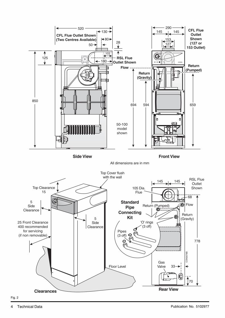
Fig. 2
CO
N00
78B
CFL FlueOutletShown(127 or
153 Outlet)
CFL Flue Outlet Shown(Two Centres Available)
RSL FlueOutletShown
RSL FlueOutlet Shown
25 Front Clearance400 recommended
for servicing(if non removable)
50-100modelshown
103

Publication No. 5102977 5
Introduction
Introduction
The Gas Safety (Installation and Use) Regulations 1998.
This appliance must be installed and serviced by acompetent person, in accordance with the aboveregulations.
In the UK 'Corgi' Registered Installers (including the regionsof British Gas Services) undertake to work to a safe andsatisfactory standard.
Failure to install appliances correctly could lead toprosecution.
It is in your own interest, and that of safety, to ensure thatthe regulations are complied with.
Kingfisher Mf boilers are fully automatically controlled,floor standing, fan powered, balanced or conventionalflued appliances using a cast iron heat exchanger and areavailable in outputs ranging from 11.72 - 29.31 kW (40,000- 100,000 Btu/h)
The boilers are designed for use on fully pumped openvented or sealed water systems with an indirect hot watercylinder or open vented gravity systems. THEY MUSTNOT BE CONNECTED TO A DIRECT CYLINDER.
The boilers are for use on Natural Gas (G20) only.
Samples of the Kingfisher Mf gas boilers have beenexamined by Advantica Technologies Limited, a UnitedKingdom Notified Body. The range is certified to complywith the essential requirements of the Gas ApplianceDirective 90/396/EEC, the Low Voltage Directive 72/23/EEC and shows compliance with the Electro MagneticCompatibility Directive 89/336/EEC, the Boiler EfficiencyDirective 92/42/EEC and are therefore permitted to carrythe CE Mark.
Delivery & Kits Available
RSL Model is delivered in two packages (1) the boiler withfittings and (2) the flue assembly.CFL Model is delivered in one package.
Various flue kits and other options for the Kingfisher Mfrange of boilers are shown on Pages 38 & 39.
Health and Safety Information for the Installerand Service Engineer
Under the Consumer Protection Act 1987 and Section 6of the Health and Safety at Work Act 1974, we are requiredto provide information on substances hazardous to health.
Small quantities of adhesives and sealants used in theproduct are cured and present no known hazards.
The following substances are also present.
Insulation and Seals
Material - Man Made Mineral Fibre.
Description - Boards, Ropes, Gaskets.
Known Hazards - Some people can suffer reddeningand itching of the skin. Fibre entry into the eye willcause foreign body irritation which can cause severeirritation to people wearing contact lenses. Irritation torespiratory tract.
Precautions - Dust goggles will protect eyes. Peoplewith a history of skin complaints may be particularlysusceptible to irritation. High dust levels are only likelyto arise following harsh abrasion. In general, normalhandling and use will not present high risk, follow goodhygiene practices, wash hands before, touching eyes,consuming food, drinking or using the toilet.
First Aid - Medical attention must be sought followingeye contact or prolonged reddening of the skin.
Codes of Practice
The boiler must be installed in accordance with: The GasSafety (Installation and Use) Regulations 1998 and thecurrent issue of:-
The Building Regulations, Building Standards (Scotland)Regulations, Local Building Regulations, Model and localWater Undertaking Bye-laws, IEE Wiring Regulations andHealth & Safety Document No. 635 "The Electricity atWork Regulations 1989".
For Ireland install in accordance with I.S. 813 "Installationof Gas Appliances".
IMPORTANTThis appliance has been certified for safety. It is therefore important that no external control device (e.g. fluedampers, economisers, etc.) be directly connected to the appliance unless covered by these Installation &Service Instructions or otherwise recommended in writing. Any direct connection of a control device notapproved by Potterton could invalidate the CE Certification and normal appliance warranty.
Publication No. 51029776 Installation Requirements
1. Installation Requirements
1.1 Gas Supply
The meter and supply pipes must be capable of deliveringthis quantity of gas in addition to the demand from any otherappliances in the house and must be governed at themeter.
On 90 & 100 models, due to the gas flow rate required,22mm gas supply pipe should be used up to the inletconnection of the gas cock on the boiler.
The complete installation must be tested for gas soundnessand purged as described in BS6891.
1.2 Electricity Supply
230V ~ 50Hz via a fused double pole switch with a contactseparation of at least 3 mm in both poles adjacent to theboiler. Power consumption is approximately 80W. Theremust be only one common isolator for the boiler and itscontrol system and it must provide complete electricalisolation. A plug (if fitted) must be accessible to the userafter installation of the appliance.
Fuse the supply at 3 A. The minimum requirement for thepower supply cable is that it should be a PVC sheathedcord at least 0.75 mm² (24 x 0.2 mm) (code designationHO5 VV-F or HO5 VVH2-F) as specified in table 16 ofBS6500:1984.
All wiring external to the boiler shall comply with the latestIEE Wiring Regulations, and any local regulations whichapply.
WARNING: THIS APPLIANCE MUST BE EARTHED.
In the event of an electrical fault after installation of theboiler, preliminary electrical systems checks must becarried out i.e. Earth Continuity, Short Circuit, Polarity andResistance to Earth.
1.3 Location of Boiler
The boiler is not suitable for external installation. The boilermust stand firm and level. No special floor protection isneeded, but finishes which soften when warm e.g. linoleumand plastic floor tiles should be removed or may beprotected by an insulating sheet at least 10mm thick.
The boiler must be installed so that the flue terminal isexposed to the external air. It is important that the positionof the terminal allows the free passage of air across it at alltimes.
The boiler is suitable for installation against a combustiblewall e.g. wood cladding, provided that the flue duct is not
closer than 25 mm to combustible material. A metal sleeveshould be installed to surround the flue duct to provide a25mm annular space. Further guidance is given inBS5440:1:2000, sub-clause 4.4.
If the boiler is to be installed in a timber framed buildingit should be fitted in accordance with the Institute of GasEngineers document IGE/UP/7/1998 (also, British GasService publication Part 19 - Building and Kitchen Work).If in doubt advice must be sought from Potterton.
RSL boilers may be installed in any room, although particularattention is drawn to the requirements of the current IEEWiring Regulations and, in Scotland, the electrical provisionsof the Building Standards applicable in Scotland withrespect to the installation of the boiler in a room containinga bath or shower.
CFL boilers must not be installed in bath, shower rooms, orrooms used as sleeping accommodation.
RSL Models: Where a room-sealed appliance is installed ina room containing a bath or shower, any electrical switchor appliance control, utilising mains electricity should be sosituated that it cannot be touched by a person using thebath or shower.
CFL Models: Conventional flue boilers can be installedeither in a kitchen or utility room or inside a suitablyventilated, purpose designed or modified compartment.
Where the installation of the boiler will be in an unusualposition, special procedures may be necessary and BS6798and BS5546 give detailed guidance on this aspect.
A compartment used to enclose the boiler must be designedand constructed specifically for this purpose. An existingcompartment may be used provided that it is modified forthe purpose. Details of essential features of compartmentdesign including airing cupboard installations are given inBS6798 and BS5546 and should be complied with.
RSL Models: If the boiler is fitted under a worksurface it maybe located next to or between kitchen cabinets or fittingsproviding that the front of the boiler case is visible andunobstructed, the special requirements for an enclosedcompartment will not apply
If the boiler is to be fitted under a worksurface, theworksurface may need to be removed to install the boiler.It is advisable that the worksurface be removable to allowaccess for servicing if required.
If the boiler is to be fitted in a run of kitchen units it isrecommended that the boiler is fitted first or the adjacentunits removed.

Publication No. 5102977 7Installation Requirements
The boiler requires the clearances shown in Fig. 2.
Conventional Flue Models - See Page 7 & 8.Balanced Flue Models - See Pages 9 & 10.
Conventional Flue Models
1.4 Air Supply
The air requirements must meet BS 5440 Part 2.
The room in which the boiler is installed must be ventilated.Ventilation of the room containing the boiler shall includeair for combustion and correct operation of the flue (ieDraught Diverter dilution).
A permanent air vent shall be provided in an outside wallof the building either at high or low level in accordance withTable 1.
The opening may be:
a) Directly into the room or space containing the boileror indirectly via an opening of at least the samearea.
b) Via a duct either directly into the room or space orindirectly via an opening of at least the same freearea.
Where air is drawn indirectly from outside through morethan two air vents refer to BS 5440 Part 2.
Where an extraction fan is fitted in the room containing theboiler, special ventilation requirements must beimplemented. Refer to BS 5440 Part 2.
Any grille and/or duct should be so sited and of a type notto become easily blocked or flooded and should offer lowresistance to airflow.
If the boiler is installed in a compartment, permanent airvents are required in the compartment, one at high leveland one at low level (Table 2), either direct to the outsideair or to a room.
Both high level and low level air vents must communicatewith the same room or must be on the same wall to outsideair.
If the boiler is installed in a compartment with a door, allowat least 25 mm clearance between the front of the boilerand door for air movement. All other clearances are as Fig.2.
Fig. 3
Table 1
Combustion Air
Free Area cm sq.
CFL40 35CFL50 51CFL60 68CFL70 84CFL80 101CFL90 117CFL100 134
Table 2
Compartment Ventilation
Free Area cm sq. High Level Low Level
CFL40 132 264CFL50 165 330CFL60 198 396CFL70 231 462CFL80 264 528CFL90 297 594CFL100 331 662
Publication No. 51029778
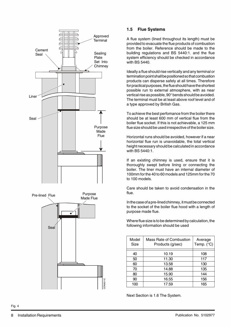
1.5 Flue Systems
A flue system (lined throughout its length) must beprovided to evacuate the flue products of combustionfrom the boiler. Reference should be made to thebuilding regulations and BS 5440:1. and the fluesystem efficiency should be checked in accordancewith BS 5440.
Ideally a flue should rise vertically and any terminal ortermination point shall be positioned so that combustionproducts can disperse safely at all times. Thereforefor practical purposes, the flue should have the shortestpossible run to external atmosphere, with as nearvertical rise as possible, 90° bends should be avoided.The terminal must be at least above roof level and ofa type approved by British Gas.
To achieve the best perfomance from the boiler thereshould be at least 600 mm of vertical flue from theboiler flue socket. If this is not achievable, a 125 mmflue size should be used irrespective of the boiler size.
Horizontal runs should be avoided, however if a nearhorizontal flue run is unavoidable, the total verticalheight necessary should be calculated in accordancewith BS 5440:1.
If an existing chimney is used, ensure that it isthoroughly swept before lining or connecting theboiler. The liner must have an internal diameter of100mm for the 40 to 60 models and 125mm for the 70to 100 models.
Care should be taken to avoid condensation in theflue.
In the case of a pre-lined chimney, it must be connectedto the socket of the boiler flue hood with a length ofpurpose made flue.
Where flue size is to be determined by calculation, thefollowing information should be used
Next Section is 1.6 The System.
Installation Requirements
Fig. 4
ModelSize
405060708090100
Mass Rate of CombustionProducts (g/sec)
10.1911.3013.5814.8815.9016.5517.59
AverageTemp. (°C)
108117130135144156165
Seal
Liner
ApprovedTerminal
CementSeal Sealing
PlateSet IntoChimney
Pre-lined Flue
Seal
CO
N00
11C
PurposeMadeFlue
PurposeMade Flue
Publication No. 5102977 9Installation Requirements
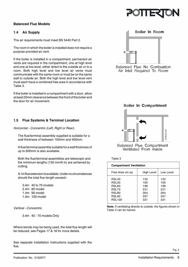
Balanced Flue Models
1.4 Air Supply
The air requirements must meet BS 5440 Part 2.
The room in which the boiler is installed does not require apurpose provided air vent.
If the boiler is installed in a compartment, permanent airvents are required in the compartment, one at high leveland one at low level, either direct to the outside air or to aroom. Both high level and low level air vents mustcommunicate with the same room or must be on the samewall to outside air. Both the high level and low level ventmust each have a combined free area in accordance withTable 3.
If the boiler is installed in a compartment with a door, allowat least 25mm clearance between the front of the boiler andthe door for air movement.
1.5 Flue Systems & Terminal Location
Horizontal - Concentric (Left, Right or Rear).
The flue/terminal assembly supplied is suitable for awall thickness of between 150mm and 400mm.
A flue/terminal assembly suitable for a wall thickness ofup to 600mm is also available.
Both the flue/terminal assemblies are telescopic andthe minimum lengths (150 mm/6 in) are achieved bycutting.
A 1m flue extension is available. Under no circumstancesshould the total flue length exceed:-
3.4m 40 to 70 models2.4m 80 model1.4m 90 model1.0m 100 model
Vertical - Concentric.
3.4m 40 - 70 models Only
Where bends may be being used, the total flue length willbe reduced, see Pages 17 & 18 for more details.
See separate Installation Instructions supplied with theflue.
Fig. 5
Table 3
Compartment Ventilation
Free Area cm sq. High Level Low Level
RSL40 132 132RSL50 165 165RSL60 198 198RSL70 231 231RSL80 264 264RSL90 297 297RSL100 331 331
Note: If ventilating directly to outside, the figures shown inTable 3 can be halved.
Publication No. 510297710
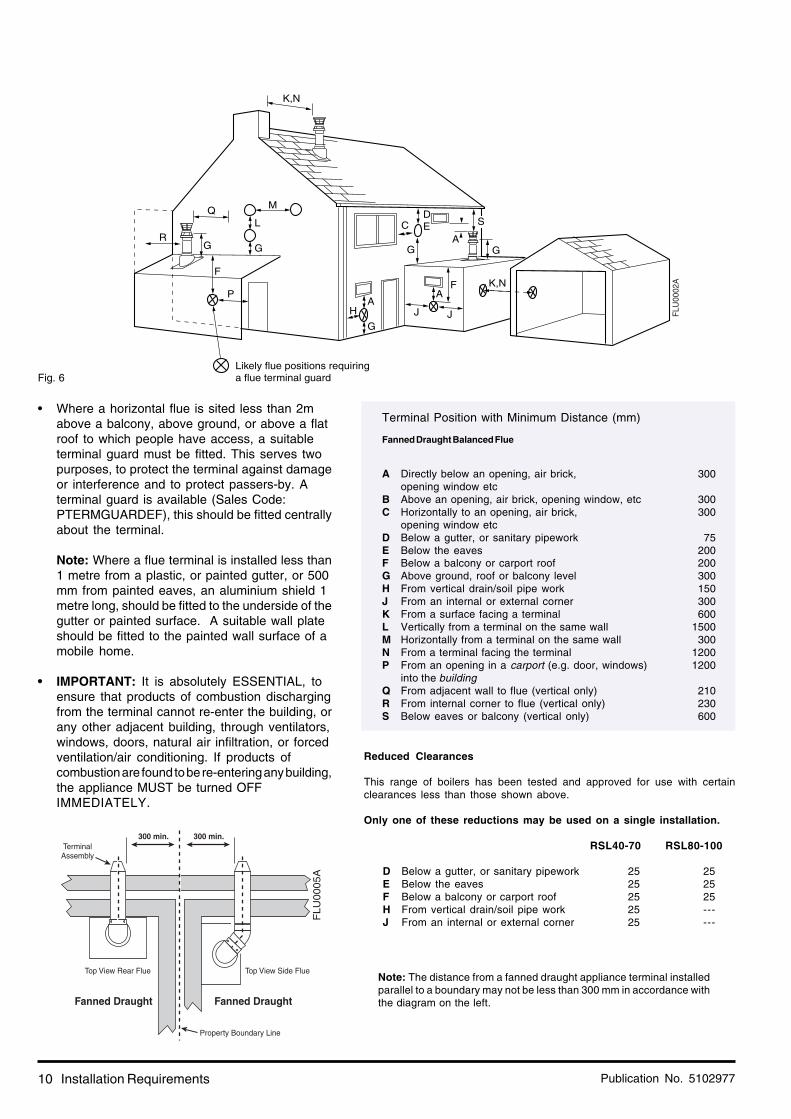
• Where a horizontal flue is sited less than 2mabove a balcony, above ground, or above a flatroof to which people have access, a suitableterminal guard must be fitted. This serves twopurposes, to protect the terminal against damageor interference and to protect passers-by. Aterminal guard is available (Sales Code:PTERMGUARDEF), this should be fitted centrallyabout the terminal.
Note: Where a flue terminal is installed less than1 metre from a plastic, or painted gutter, or 500mm from painted eaves, an aluminium shield 1metre long, should be fitted to the underside of thegutter or painted surface. A suitable wall plateshould be fitted to the painted wall surface of amobile home.
• IMPORTANT: It is absolutely ESSENTIAL, toensure that products of combustion dischargingfrom the terminal cannot re-enter the building, orany other adjacent building, through ventilators,windows, doors, natural air infiltration, or forcedventilation/air conditioning. If products ofcombustion are found to be re-entering any building,the appliance MUST be turned OFFIMMEDIATELY.
Installation Requirements
Fig. 6
M
G
G
H
F
L
G
AA
F
J
K,N
DE
J
Likely flue positions requiring a flue terminal guard
C
Q
AG
K,N
G
FLU
0002
A
P
S
R
Fanned Draught Balanced Flue
A Directly below an opening, air brick,opening window etc
B Above an opening, air brick, opening window, etcC Horizontally to an opening, air brick,
opening window etcD Below a gutter, or sanitary pipeworkE Below the eavesF Below a balcony or carport roofG Above ground, roof or balcony levelH From vertical drain/soil pipe workJ From an internal or external cornerK From a surface facing a terminalL Vertically from a terminal on the same wallM Horizontally from a terminal on the same wallN From a terminal facing the terminalP From an opening in a carport (e.g. door, windows)
into the buildingQ From adjacent wall to flue (vertical only)R From internal corner to flue (vertical only)S Below eaves or balcony (vertical only)
Terminal Position with Minimum Distance (mm)
Note: The distance from a fanned draught appliance terminal installedparallel to a boundary may not be less than 300 mm in accordance withthe diagram on the left.
300
300300
75200200300150300600
1500300
12001200
210230600
Top View Rear Flue Top View Side Flue
TerminalAssembly
Property Boundary Line
Fanned DraughtFanned Draught
300 min. 300 min.
FLU
0005A
Reduced Clearances
This range of boilers has been tested and approved for use with certainclearances less than those shown above.
Only one of these reductions may be used on a single installation.
RSL40-70 RSL80-100
D Below a gutter, or sanitary pipework 25 25E Below the eaves 25 25F Below a balcony or carport roof 25 25H From vertical drain/soil pipe work 25 ---J From an internal or external corner 25 ---
Publication No. 5102977 11Installation Requirements
1.6 The System
If plastic pipe is used for the central heating circuit theremust be a run of at least 1m of uninsulated copper pipe fromthe boiler flow and return connections.
The boiler must be used on INDIRECT hot water systemsonly. It is suitable for use on open vented gravity domestichot water/pumped central heating systems or, fully pumpedsystems which may be sealed or open vented.
Existing systems should be thoroughly cleansed prior toboiler installation.
The system should be designed so that the maximumstatic head does not exceed 30.5 m and there is a minimumon fully pumped systems of 300 mm. See Fig. 8.
Gravity domestic hot water circuits should have a minimumcirculating head of 1.2 m. See Fig. 7. Horizontal pipe runsshould be kept to a minimum. To prevent reverse circulationin the gravity circuit when the pump is running an injector teeis incorporated.
The pump should preferably be fitted in the flow, thoughinstallation in the return is acceptable providing care istaken to ensure air is not drawn into the system due to thenegative pressure effects of the pump. Isolating valvesmust be fitted as close as possible to allow replacementwithout system draining.
Drain off taps should be fitted in the pipework close to theboiler and in the low points of the system. A drain point isalso provided on the heat exchanger should the boiler needdraining - see Fig. 22.
Combined Gravity Hot Water Pumped CentralHeating Systems.
It is recommended that a cylinder thermostat and zonevalve are used to control the temperature of the hot waterand that a by-pass be installed in the gravity circuit. Asuggested method of doing this is shown in Fig. 7. where thebathroom radiator is connected into the gravity circuit andis fitted with two lockshield valves. Mechanically operatedthermostatic domestic hot water temperature control valveswhich allow the boiler to operate when the valve is closedor partially closed MUST NOT BE FITTED UNLESS abypass radiator is fitted. Note: The boiler has one flow andtwo return connections. On combined gravity DHW/Pumpedcentral heating a Tee will be needed in the flow which mustbe fitted directly to the connecting pipe provided.
Fully Pumped Systems
The pump must be wired directly to the terminal block (SeeFig. 20) as it will allow the pump to be controlled by the over-run device. This will ensure that the pump will continue torun after boiler shut down thus preventing nuisanceoperation of the overheat thermostat.
If a three port diverter valve is used as shown in Figs.8 &9, a by-pass is not necessary since one circuit is alwaysopen. Where a pair of two port valves are used, a by-passis necessary. It should be fitted with a lockshield valve andbe adjusted to maintain a minimum flow through the boilerof 4.5 litres/min (1 gal/min) see Figs. 8 & 9.Systems fitted with controls which allow the boiler tooperate when both the hot water and central heatingcircuits are closed i.e. mechanically operated thermostaticcontrol valves, must be fitted with a by-pass circuit capableof:-
1. Dissipating a minimum of 1kW (3,400 Btu/h)2. Maintaining a minimum water flow through the
boiler of 9 litres/min (2 gal/min).
A suggested method of meeting these requirements byusing a bathroom radiator fitted with two lockshield valvesis shown in Figs. 8 & 9.
Diagrammatic layouts of a fully pumped system and acombined pumped central heating/gravity hot water systemare shown in Figs. 7 & 8.
Sealed Systems (Fully Pumped)
InstallationThe installation must comply with the requirements of BS6798: 1987 and BS 5449: Pt 1. The British Gas publication"British Gas Specification for Domestic Wet Central HeatingSystems" should also be consulted.
Safety ValveA non-adjustable spring-loaded safety valve, preset tooperate at 3 bar (45lbf/in²) shall be used. It must complywith BS 6759: Pt 1. and include a manual testing device. Itshall be positioned in the flow pipe either horizontally orvertically upwards and close to the boiler. No shut-offvalves are to be placed between the boiler and the safetyvalve. The valve should be installed into a discharge pipewhich permits the safe discharge of steam and hot watersuch that no hazard to persons or damage to electricalcomponents is caused.
Pressure GaugeA pressure gauge incorporating a fill pressure indicator,covering the range 0 - 4 bar (60 lbf/in²) shall be fitted to thesystem. It should be connected to the system, preferablyat the same point as the expansion vessel. Its locationshould be visible from the filling point.
Expansion VesselA diaphragm type expansion vessel to BS 4814: Pt 1. shallbe fitted close to the inlet side of the pump. The connectingpipework should not be less than 15mm. Pipeworkconnecting the expansion vessel should not incorporatevalves of any sort. Methods of supporting the vessel aresupplied by the vessel manufacturer. The nitrogen or aircharge pressure of the expansion vessel shall not be lessthan the hydrostatic head, (height of the top point of thesystem above the expansion vessel).
Publication No. 510297712 Installation Requirements
CylinderThe hot water cylinder must be an indirect coil type or adirect cylinder fitted with an immersion calorifier suitablefor operating at a gauge pressure of 0.3 bar (5 lbf/in²) inexcess of safety valve setting. Single feed indirect cylindersare not suitable for sealed systems.
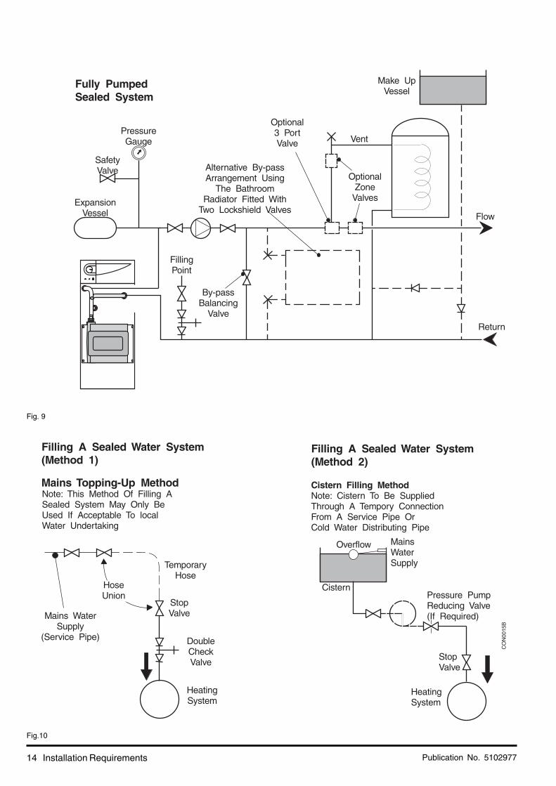
Method of Make-upProvision shall be made for replacing water loss from thesystem either:-
i) from a make-up vessel or tank mounted in a positionhigher than the top point of the system, and connectedthrough a non-return valve to the system on thereturn side of the hot water cylinder or the return sideof all heat emitters.or
ii) where access to a make-up vessel would be difficultby using the mains top up method or a remoteautomatic pressurisation and make-up unit as shownin Fig. 10.
Mains ConnectionThere shall be no connection to the mains water supply orto the water storage tank which supplies domestic hotwater even through a non-return valve, without the approvalof the Local Water Authority.
Filling PointThe system shall be fitted with a filling point at low levelwhich incorporates a stop valve to BS 1010 and a doublecheck valve of an accepted type to be fitted in this orderfrom the system mains, see Fig. 10.
Boiler Heat Exchanger: 6.5 litresSmall Bore Pipework: 1 litre per kW of system
outputMicro Bore Pipework: 7 litresSteel Panel Radiators: 8 litres per kW of system
outputLow Water Capacity Radiators: 2 litres per kW of system
outputHot Water Cylinder: 2 litres
If the system is extended, the expansion vessel volumemay have to be increased unless provision has been madefor extension. Where a vessel of the calculated size is notavailable, the next available larger size should be used.The boiler flow temperature is controlled at approximately82°C.
The vessel size can now be determined from the informationin Table 4 where V = System volume in litres.
1.0
1.0
V x 0.087
Vessel Charge Pressure (bar)
Initial System Pressure (bar)
Expansion Vessel Volume (litres)
0.5
1.0
V x 0.11
Table 4.
To size the expansion vessel it is first necessary tocalculate the volume of water in the system in litres. Thefollowing volumes may be used as a conservative guide tocalculating the system volume.
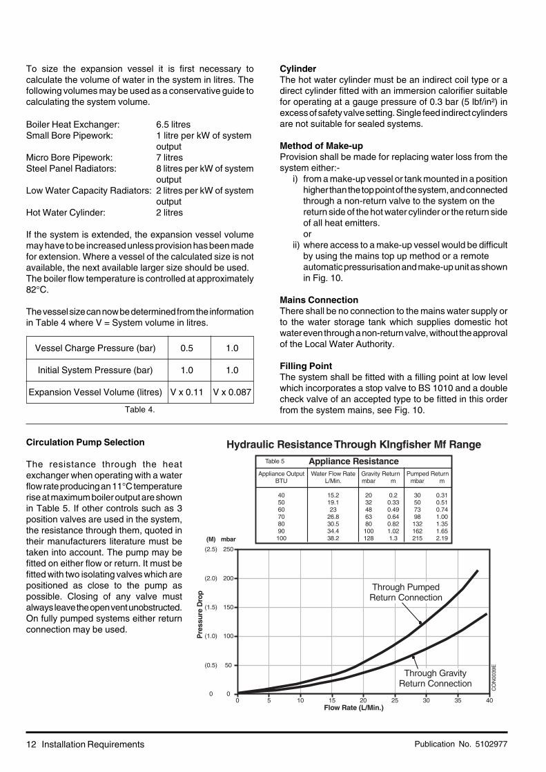
Circulation Pump Selection
The resistance through the heatexchanger when operating with a waterflow rate producing an 11°C temperaturerise at maximum boiler output are shownin Table 5. If other controls such as 3position valves are used in the system,the resistance through them, quoted intheir manufacturers literature must betaken into account. The pump may befitted on either flow or return. It must befitted with two isolating valves which arepositioned as close to the pump aspossible. Closing of any valve mustalways leave the open vent unobstructed.On fully pumped systems either returnconnection may be used.

Publication No. 5102977 13
CO
N00
93B
Installation Requirements
Fig. 8
Fig. 7
Publication No. 510297714 Installation Requirements
Fig. 9
Fig.10

Publication No. 5102977 15
2. Installation
2.1 Install the boiler
These instructions assume you have decidedon where the boiler will be located and the typeof flue system to be used.
1. Carefully unpack the boiler. Remove andplace aside the tailpipe/gravity stat kit andon CFL boilers, the ancillary bag containingthe top and rear blanking plates with sealand control panel.
2. Do not discard any packaging until all theitems are accounted for.
3. Temporarily position the boiler to ensurewhere required, the top cover touches thewall. This sets the minimum rear clearancefor the pipework. Mark the position on thefloor.
4. Remove the plinth - 2 screws.5. Remove the front door - 2 screws, unhook
and lift off.6. Remove the controls panel - open flap,
remove screw, unhook, disconnect the in-line connector and lift away.
7. Remove the top cover - 2 screws, pullforward and lift off.
Installation
Fig. 12
2.2 Install the flue
Install the flue type as required.
Conventional Flue:
1. Loosen the 4 screws securing the flue spigotto the boiler, line the spigot up with the flueand fully tighten the screws.
Note: From its fully rearward position thespigot will move forward 50mm.
CO
N00
21F
Fig. 11

Publication No. 510297716 Installation
Fig. 14
Centre ofthe Flue
Cut Out Hole
Front Edge
Rear Edge
Top View of the Work top
Minimumfrom Wall
Maximumfrom Wall
135Max.
C/L. C/L.
115
85 Minimum
200
200
100
100
200
200
CO
N00
75A
2. Attach the flue to the flue spigot.
This product is fitted with a combustionproducts discharge safety device (TTB) whichmust not be taken out of operation at anytime. The component is fitted to ensure thatany blockage or partial blockage of the fluedoes not result in combustion productsdischarging into the room.
Fitting under a Worktop (CFL Models)
1. Remove the top blanking plate from theboiler (if already assembled).
2. See Section 4.9 on page 28 of the Installation& Service Instructions, remove the productsdischarge safety device (TTB) and carefullyplace on top of the appliance.
3. Remove the flue spigot from the applianceby removing the 4 adjusting screws.
4. Mark the centre of the flue on the work topand cut a 200 mm square hole from thiscentre point. The centre point should be aminimum of 85 mm from the wall and amaximum of 135 mm from the wall beingdependent on the boiler position.
5. Place boiler in position under the work top.
6. Re-fit the flue spigot as shown in Fig. 13.
7. Refit the products discharge safety device(TTB) back onto the flue spigot and securewith the screw.
8. It is a requirement that after disturbing theproducts discharge safety device, a fulloperational check should be made to ensurecorrect operation i.e. with the boiler fullyoperating, temporarily block the flue. Thesafety discharge device should operate andthe boiler go to lockout in less than 2minutes.
9. Unblock the flue after the test.
Wall
Ceiling(Combustible
Material)
FlueSpigot
80Min.
Plus 50max
Minimum25mm
clearance
ConventionalFlue
Top BlankingPlate
RearBlanking
Plate
FlueSpigot
Air Box CO
N00
34E
Fig. 13

Publication No. 5102977 17
Fitting the Blanking Plate
1. If the flue is not fitted in the fully forwardposition, the rear blanking plate will need tobe cut to size, cut trim to length as required.See Fig. 15.
• If fitting under a worktop then drill 2 pilotholes through the holes in the rear blankingplate plate and into the work top. Securethe plate using 2 woodscrews (notsupplied).
2. Locate the top blanking plate as shown inFig. 15.
Balanced Flue:
1. Mark the flue outlet hole position on the wallas illustrated.
Note: Ensure that the correct allowance ismade for side outlet when the boiler is notbeing pushed fully back.
2. Carefully cut hole through wall.
Maximum flue lengths are as follows:
40 - 70 models 3.4 m80 model 2.4 m90 model 1.4 m100 model 1.0 m
These are for rear or side flue applicationssee Page 17 Fig. 16.
3. Determine dimension X +20 mm See Fig.13.
4. Extend telescopic flue to the required length,minimum 20 mm overlap.
5. Drill through the pilot hole and secure witha self tapping screw.
6. Wrap tape around the joint on the outer ductto seal the flue, slide drip ring into position tocoincide with the air gap in the wall cavity.
7. Slide the flue through the hole until it stopson the pin.
8. The boiler is supplied with the flue elbow setfor the rear. For side outlet slacken thescrews, turn the elbow as required andretighten screws.
Note: Ensure that the seals are still correctlylocated.
Air Box
Top Edge ofWork top
CutOutHole
Top ofBoiler
Work top
CO
N00
76A
Fit TopBlankingPlate
Refit FlueSpigot
Cut to size(if required) Fit Trim
Screw RearBlanking Plateto work surface
Installation
Fig. 16
CO
N00
77A
180 min180 min
778
110 Dia.Hole
31 min
73 min
70 Min.
Fig. 15
Publication No. 510297718 Installation
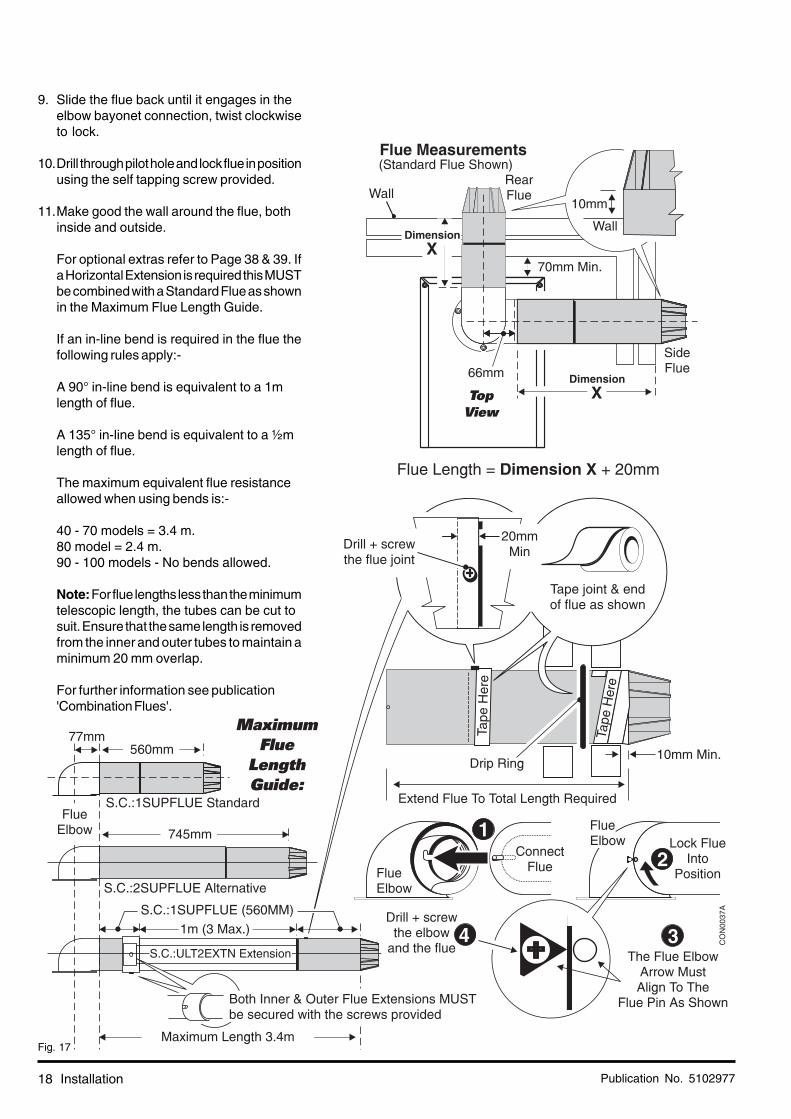
9. Slide the flue back until it engages in theelbow bayonet connection, twist clockwiseto lock.
10.Drill through pilot hole and lock flue in positionusing the self tapping screw provided.
11.Make good the wall around the flue, bothinside and outside.
For optional extras refer to Page 38 & 39. Ifa Horizontal Extension is required this MUSTbe combined with a Standard Flue as shownin the Maximum Flue Length Guide.
If an in-line bend is required in the flue thefollowing rules apply:-
A 90° in-line bend is equivalent to a 1mlength of flue.
A 135° in-line bend is equivalent to a ½mlength of flue.
The maximum equivalent flue resistanceallowed when using bends is:-
40 - 70 models = 3.4 m.80 model = 2.4 m.90 - 100 models - No bends allowed.
Note: For flue lengths less than the minimumtelescopic length, the tubes can be cut tosuit. Ensure that the same length is removedfrom the inner and outer tubes to maintain aminimum 20 mm overlap.
For further information see publication'Combination Flues'.
Fig. 17

Publication No. 5102977 19Installation
Fig. 19
2.3 Connect the Gas Supply
1. Ensure that the gas supply is isolated.2. Disconnect the gas cock from the gas valve.3. Connect the gas supply to the gas cock
using a suitable adaptor.
Important:Do not solder the fitting whilst
assembled to the gas cock.
The pipe diameter required will depend onthe boiler model and the pipe length fromthe gas meter. Ensure that the gas supplypipe is selected in accordance with BS 6891so that an adequate gas supply to the boileris provided.
4. Connect the gas cock to the gas valve.
Do not turn the gas supply on at this stage.
2.4 Connect the Water System
When attaching the standard pipe connecting kit to the boiler please note that the seal is made by use of an 'O' ring,therefore some pipe movement will be evident even though a water tight seal has been achieved. Excessive force isnot necessary and could result in damage to the appliance.
1. Connect system pipework to the boiler, compression fittings should be used. Arrange pipework to ensure correct ventingof pipes and boiler. On gravity systems a tee is required in the flow which must be fitted directly to the connecting pipesupplied. Note: Drain off taps should be installed at the lowest points in the system.
2. If on a Gravity DHW system position the overheat thermostat as shown.3. To do this - unscrew the overheat thermostat from the flow pipe and re-attach as shown using the bracket and screw
found in the tail pipe/gravity stat kit.
CO
N00
25B
Gas PipeInstalled
GasCock
Gas CockRc ½"
½" B.S.P.Female
GasValve
Connect Gas Pipe
Stage1
Stage2
'ON'
'OFF'
DisconnectGas Cockfrom the
Gas Valve
Return(Pumped)
Return(Pumped)
CO
N00
20D
Fig. 18

Publication No. 510297720 Installation
Fig. 20
2.5 Connect the Power Supply Cable
1. Cable clamping is provided on the front ofthe controls panel. Feed the cables up andover the back of the chassis, through theclamp and into the terminal connection.
Note: When connecting the power supplycable, ensure that the length of the earthwire is such, that if the power supply cablepulls out of the cable clamp the live andneutral wires become taut before the earthwire.
If fitting the optional integral programmer,refer to the instructions supplied with it forwiring details.
For Gravity DHW/Pumped CH Systems,the pump should be wired externally.
For Fully Pumped Systems, connect pumpto Pump 'L, N, E' on the terminal block.
2. Where no integral programmer is fitted,connect the wires as follows;
Gravity DHW/Pumped CH Systems
a. Fit a link between terminals MAINS 'SwL'and MAINS 'L'.
b. Switched live from external gravity DHWcontrol circuit to MAINS 'SwL'.
c. Neutral to MAINS 'N'.d. Earth to MAINS 'E'.e. The pump should be wired externally.
Fully Pumped Systems
a. Permanent live to terminal MAINS 'L'b. Switched live from external controls to
MAINS 'SwL'.c. Neutral to MAINS 'N'.d. Earth to MAINS 'E'.e. Pump to PUMP 'L, N, E'.
Open Vented Fully Pumped Systems
The boiler is fitted as standard with anoverheat thermostat and pump overrundevice which requires a permanent live tothe boiler. This is the recommendedinstallation method (see above).
However, in replacement situations where apermanent live is not available, it is possibleto wire the boiler with 3 core cable as follows,providing the system has a separate cold

Publication No. 5102977 21Installation
Fig. 21
feed and vent pipes (close coupling isacceptable) see BS 5449 for further details.
a. Re-position the overheat thermostat toGravity DHW position as explained under2.4, page 19.
b. Switched live from external control circuitto MAINS 'SwL'.
c. Fit a link between terminals MAINS 'SwL'and MAINS 'L'
d. Neutral to MAINS 'N'.e. Earth to MAINS 'E'.f. The pump should be wired externally.
3. Take up excess slack in the cables betweenthe terminal block and the cable clamp,then tighten the cable clamp screws.Ensure sufficient slack is available to thecable clamps to allow the control panel tohinge freely. Check by opening the controlpanel.
If fitting the optional integral programmer goto section 2.6 before performing steps 4and 5 below.
4. Secure the controls assembly to the chassisusing the screw previously removed.
5. Carry out preliminary electrical systemchecks i.e. Earth Continuity, Short Circuit,Polarity and Resistance to Earth.
Frost Thermostat:If a Frost Thermostat is to be fitted, theconnections should be made in the wiringexternal to the boiler. Refer to the wiringinstructions with the thermostat.
Do not switch on the electricity supply atthis stage.
2.6 Install the Optional Programmer
1. If fitting the optional integral programmer,refer to the instructions supplied with it forinstallation and wiring details.

Publication No. 510297722 Commissioning
3. Commissioning
ImportantWhen checking for gas soundness open
all windows and doors in the room.Extinguish all naked lights, cigarettes, pipes, etc.
ImportantThe commissioning and boiler adjustment must
only be carried out by a suitably qualifiedperson. Potterton offer this service on a
chargeable basis.
Fig. 22
Top Cover(RSL Model shown)
Flue Elbow(RSL Model shown)
CO
N00
79B
ImportantState of adjustment - Check that the stateof adjustment given on the data plate iscompatible with local supply conditions.
Publication No. 5102977 23
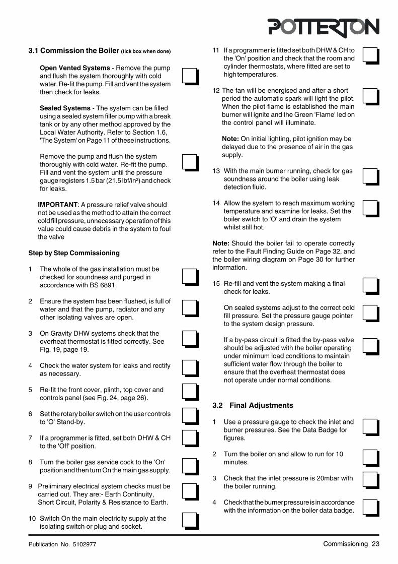
3.1 Commission the Boiler (tick box when done)
Open Vented Systems - Remove the pumpand flush the system thoroughly with coldwater. Re-fit the pump. Fill and vent the systemthen check for leaks.
Sealed Systems - The system can be filledusing a sealed system filler pump with a breaktank or by any other method approved by theLocal Water Authority. Refer to Section 1.6,'The System' on Page 11 of these instructions.
Remove the pump and flush the systemthoroughly with cold water. Re-fit the pump.Fill and vent the system until the pressuregauge registers 1.5 bar (21.5 lbf/in²) and checkfor leaks.
IMPORTANT: A pressure relief valve shouldnot be used as the method to attain the correctcold fill pressure, unnecessary operation of thisvalue could cause debris in the system to foulthe valve
Step by Step Commissioning
1 The whole of the gas installation must bechecked for soundness and purged inaccordance with BS 6891.
2 Ensure the system has been flushed, is full ofwater and that the pump, radiator and anyother isolating valves are open.
3 On Gravity DHW systems check that theoverheat thermostat is fitted correctly. SeeFig. 19, page 19.
4 Check the water system for leaks and rectifyas necessary.
5 Re-fit the front cover, plinth, top cover andcontrols panel (see Fig. 24, page 26).
6 Set the rotary boiler switch on the user controlsto 'O' Stand-by.
7 If a programmer is fitted, set both DHW & CHto the 'Off' position.
8 Turn the boiler gas service cock to the 'On'position and then turn On the main gas supply.
9 Preliminary electrical system checks must becarried out. They are:- Earth Continuity,Short Circuit, Polarity & Resistance to Earth.
10 Switch On the main electricity supply at theisolating switch or plug and socket.
11 If a programmer is fitted set both DHW & CH tothe 'On' position and check that the room andcylinder thermostats, where fitted are set tohigh temperatures.
12 The fan will be energised and after a shortperiod the automatic spark will light the pilot.When the pilot flame is established the mainburner will ignite and the Green 'Flame' led onthe control panel will illuminate.
Note: On initial lighting, pilot ignition may bedelayed due to the presence of air in the gassupply.
13 With the main burner running, check for gassoundness around the boiler using leakdetection fluid.
14 Allow the system to reach maximum workingtemperature and examine for leaks. Set theboiler switch to 'O' and drain the systemwhilst still hot.
Note: Should the boiler fail to operate correctlyrefer to the Fault Finding Guide on Page 32, andthe boiler wiring diagram on Page 30 for furtherinformation.
15 Re-fill and vent the system making a finalcheck for leaks.
On sealed systems adjust to the correct coldfill pressure. Set the pressure gauge pointerto the system design pressure.
If a by-pass circuit is fitted the by-pass valveshould be adjusted with the boiler operatingunder minimum load conditions to maintainsufficient water flow through the boiler toensure that the overheat thermostat doesnot operate under normal conditions.
3.2 Final Adjustments
1 Use a pressure gauge to check the inlet andburner pressures. See the Data Badge forfigures.
2 Turn the boiler on and allow to run for 10minutes.
3 Check that the inlet pressure is 20mbar withthe boiler running.
4 Check that the burner pressure is in accordancewith the information on the boiler data badge.
Commissioning
Publication No. 510297724 Service & Replacement of Parts
5 If burner pressure adjustment is required, turnthe pressure adjusting screw anti-clockwise toincrease pressure or clockwise to decrease.
6 Check at the gas meter that the gas rate iscorrect.
7 Shut down the boiler, remove the pressuregauges, re-fit the screws and check for gassoundness.
Control ThermostatAt its minimum and maximum settings, thethermostat should control the water flowtemperature at approximately 55°C - 82°C.
Set the temperature control knob to 'O' Standbyand check that the main burner shuts down.
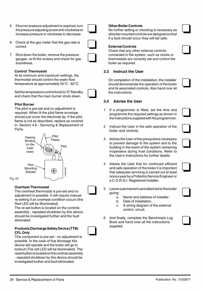
Pilot BurnerThe pilot is pre-set and no adjustment isrequired. When lit the pilot flame envelopeshould just cover the electrode tip. If the pilotflame is not as described, replace as coveredin Section 4.6 - Servicing & Replacement ofParts.
Overheat ThermostatThe overheat thermostat is pre-set and noadjustment is possible. It will require manualre-setting if an overheat condition occurs (theRed LED will be illluminated).The re-set button is located on the controlsassembly - repeated shutdown by this deviceshould be investigated further and the faulteliminated.
Products Discharge Safety Device (TTB)CFL OnlyThis component is pre-set - no adjustment ispossible. In the case of flue blockage thisdevice will operate and the boiler will go tolockout (The red LED will be illuminated). Thereset button is located on the controls assembly- repeated shutdown by this device should beinvestigated further and fault eliminated.
Other Boiler ControlsNo further setting or checking is necessary asall boiler mounted controls are designed so thatif a fault should occur they will fail safe.
External ControlsCheck that any other external controlsconnected in the system, such as clocks orthermostats are correctly set and control theboiler as required.
3.3 Instruct the User
On completion of the installation, the installershould demonstrate the operation of the boilerand its associated controls. Also hand over allthe instructions.
3.4 Advise the User
1 If a programmer is fitted, set the time andprogramme the required settings as shown inthe instructions supplied with the programmer.
2 Instruct the User in the safe operation of theboiler and controls.
3 Advise the User of the precautions necessaryto prevent damage to the system and to thebuilding in the event of the system remaininginoperative during frost conditions. Refer tothe User's Instructions for further deatils
4 Advise the User that for continued efficientand safe operation of the boiler it is importantthat adequate servicing is carried out at leastonce a year by a Potterton Service Engineer ora C.O.R.G.I. Registered Installer.
5 Leave a permanent card attached to the boilergiving:
a. Name and address of installer.b. Date of installation.c. A wiring diagram of the external
control circuit.
6 And finally, complete the Benchmark LogBook and hand over all the instructionssupplied.
Fig. 23
PilotMountingBracket
Pilot
ViewingWindow(in theoutercase)
PilotFlame
CO
N00
38A
Publication No. 5102977 25
4. Service & Replacement of PartsRead these: To ensure continued efficient operation of the appliance, it is recommended that it is checked and
cleaned as necessary at regular intervals.
The frequency of servicing will depend upon the particular installation conditions and usage but ingeneral once per year should be adequate.
It is the law that any service work must be carried out by a competent person who is C.O.R.G.I.Registered.
Before servicing, fire the appliance and check that the flames are blue. Yellow flame and excessivelifting indicate poor combustion.
WARNING: Before commencing work turn the temperature control knob to 'O' Stand-by and allow the appliance tocool, isolate the electricity supply.
If the gas valve is to be removed turn off the gas supply at the appliance service cock.
IMPORTANT: Always test for gas soundness after completing any servicing of gas carrying components and carryout functional checks of controls.
IMPORTANT: Ensure that the outer white case is correctly fitted and that the sealing strip fitted to the door is forminga tight seal with the boiler casing.
Remember to fill in the Benchmark Log Book
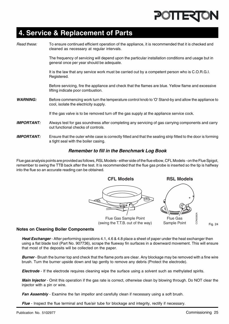
Flue gas analysis points are provided as follows, RSL Models - either side of the flue elbow, CFL Models - on the Flue Spigot,remember to swing the TTB back after the test. It is recommended that the flue gas probe is inserted so the tip is halfwayinto the flue so an accurate reading can be obtained.
Notes on Cleaning Boiler Components
Heat Exchanger - After performing operations 4.1, 4.6 & 4.8 place a sheet of paper under the heat exchanger thenusing a flat blade tool (Part No. 907736), scrape the flueway fin surfaces in a downward movement. This will ensurethat most of the deposits will be collected on the paper.
Burner - Brush the burner top and check that the flame ports are clear. Any blockage may be removed with a fine wirebrush. Turn the burner upside down and tap gently to remove any debris (Protect the electrode).
Electrode - If the electrode requires cleaning wipe the surface using a solvent such as methylated spirits.
Main Injector - Omit this operation if the gas rate is correct, otherwise clean by blowing through. Do NOT clear theinjector with a pin or wire.
Fan Assembly - Examine the fan impellor and carefully clean if necessary using a soft brush.
Flue - Inspect the flue terminal and flue/air tube for blockage and integrity, rectify if necessary.
Commissioning
Fig. 24CO
N00
80A
CFL Models RSL Models
Flue Gas Sample Point(swing the T.T.B. out of the way)
Flue GasSample Point
Publication No. 510297726
CO
N00
29G
Service & Replacement of Parts
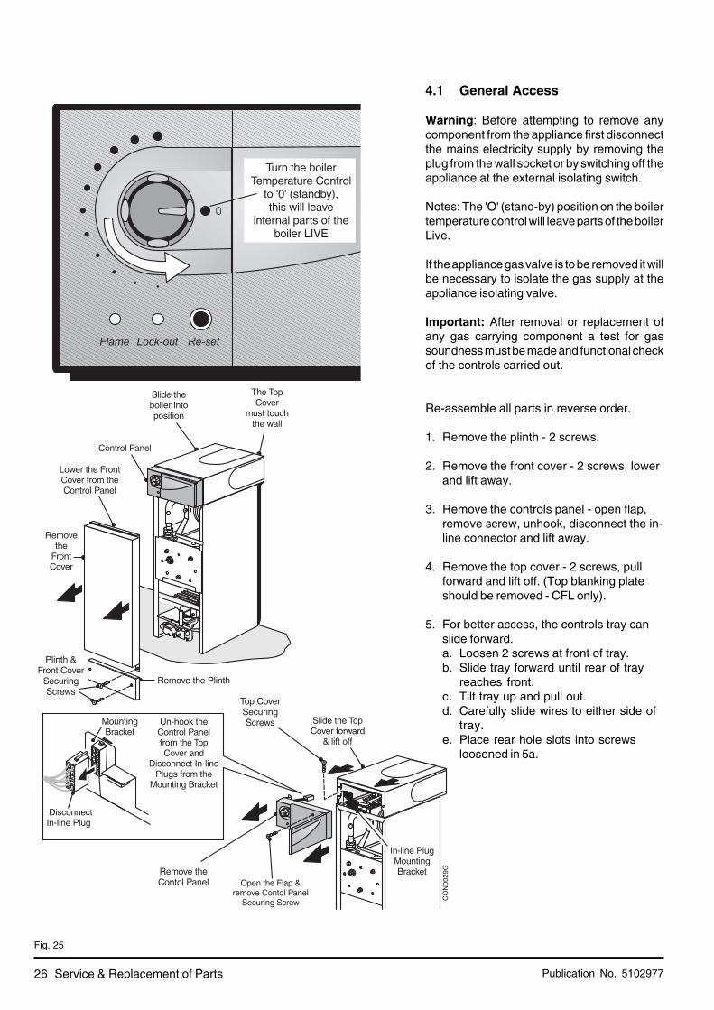
4.1 General Access
Warning: Before attempting to remove anycomponent from the appliance first disconnectthe mains electricity supply by removing theplug from the wall socket or by switching off theappliance at the external isolating switch.
Notes: The 'O' (stand-by) position on the boilertemperature control will leave parts of the boilerLive.
If the appliance gas valve is to be removed it willbe necessary to isolate the gas supply at theappliance isolating valve.
Important: After removal or replacement ofany gas carrying component a test for gassoundness must be made and functional checkof the controls carried out.
Re-assemble all parts in reverse order.
1. Remove the plinth - 2 screws.
2. Remove the front cover - 2 screws, lowerand lift away.
3. Remove the controls panel - open flap,remove screw, unhook, disconnect the in-line connector and lift away.
4. Remove the top cover - 2 screws, pullforward and lift off. (Top blanking plateshould be removed - CFL only).
5. For better access, the controls tray canslide forward.a. Loosen 2 screws at front of tray.b. Slide tray forward until rear of tray
reaches front.c. Tilt tray up and pull out.d. Carefully slide wires to either side of
tray.e. Place rear hole slots into screws
loosened in 5a.
Fig. 25

Publication No. 5102977 27
CO
N00
30D
CasingPressure
Pipe (White)
Fig. 26
4.2 Electronic Control Board
• Gain General Access - See 4.1For better access of controls tray See 4.1Note 5.
1. Disconnect all connectors and wires,unscrew the two securing screws andremove the board.
2. On re-assembly refer to the wiring diagramwhen re-connecting wires and connectors.
4.3 Air Pressure Switch
• Gain General Access - See 4.11. Remove the securing screws and allow the
control panel to pivot forwards - see 4.1Note 5.
2. Note the wire connections and disconnectthe wires to the air pressure switch.
3. Remove the screws securing the airpressure switch to the bracket.
4. Note the tube connections and remove thetubes from the switch.
5. Re-assemble in reverse order.
4.4 Temperature Sensor
• Gain General Access - See 4.11. Disconnect the wires from the sensor.2. Depress the clips on the outside of the
sensor and pull it clear of the heat exchanger.3. Re-assemble in reverse order, use fresh
conducting paste.
4.5 Overheat Thermostat
• Gain General Access - See 4.11. Disconnect the wires from the thermostat.2. Unscrew the thermostat from the pipe.3. Re-assemble in reverse order.
Service & Replacement of Parts
Publication No. 510297728
Plate onModels
50, 60 &70
CO
N00
81B To remove the Electrode,
push the Electrode back atthe base and pull down
Electrode
50-100Burner
CombustionChamber
Cover(50-100 models)
50-100 ModelBurner
40ModelBurner
CombustionChamber
Cover(40 model)
Burner
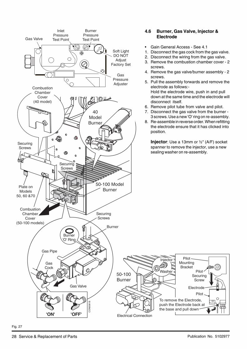
4.6 Burner, Gas Valve, Injector &Electrode
• Gain General Access - See 4.11. Disconnect the gas cock from the gas valve.2. Disconnect the wiring from the gas valve.3. Remove the combustion chamber cover - 2
screws.4. Remove the gas valve/burner assembly - 2
screws.5. Pull the assembly forwards and remove the
electrode as follows:-Hold the electrode wire, push in and pulldown at the same time and the electrode willdisconnect itself.
6. Remove pilot tube from valve and pilot.7. Disconnect the gas valve from the burner -
3 screws. Use a new 'O' ring on re-assembly.8. Re-assemble in reverse order. When refitting
the electrode ensure that it has clicked intoposition.
Injector: Use a 13mm or ½" (A/F) socketspanner to remove the injector, use a newsealing washer on re-assembly.
Fig. 27
Service & Replacement of Parts
Publication No. 5102977 29
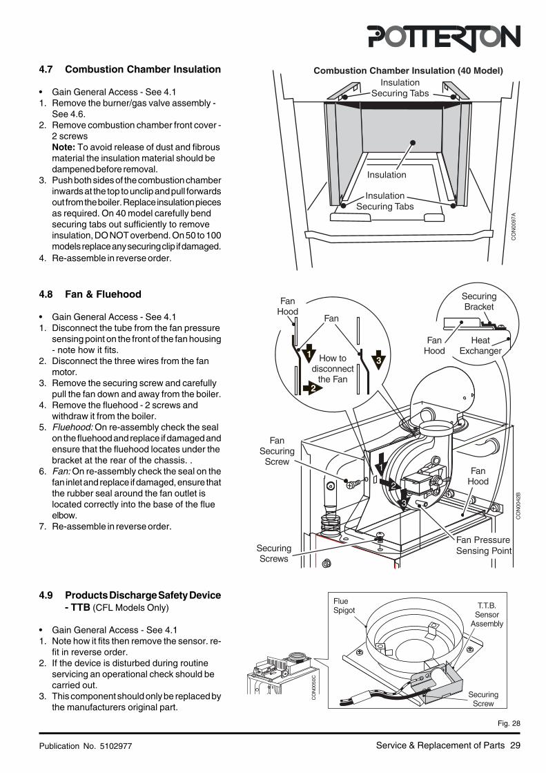
4.7 Combustion Chamber Insulation
• Gain General Access - See 4.11. Remove the burner/gas valve assembly -
See 4.6.2. Remove combustion chamber front cover -
2 screwsNote: To avoid release of dust and fibrousmaterial the insulation material should bedampened before removal.
3. Push both sides of the combustion chamberinwards at the top to unclip and pull forwardsout from the boiler. Replace insulation piecesas required. On 40 model carefully bendsecuring tabs out sufficiently to removeinsulation, DO NOT overbend. On 50 to 100models replace any securing clip if damaged.
4. Re-assemble in reverse order.
4.8 Fan & Fluehood
• Gain General Access - See 4.11. Disconnect the tube from the fan pressure
sensing point on the front of the fan housing- note how it fits.
2. Disconnect the three wires from the fanmotor.
3. Remove the securing screw and carefullypull the fan down and away from the boiler.
4. Remove the fluehood - 2 screws andwithdraw it from the boiler.
5. Fluehood: On re-assembly check the sealon the fluehood and replace if damaged andensure that the fluehood locates under thebracket at the rear of the chassis. .
6. Fan: On re-assembly check the seal on thefan inlet and replace if damaged, ensure thatthe rubber seal around the fan outlet islocated correctly into the base of the flueelbow.
7. Re-assemble in reverse order.
4.9 Products Discharge Safety Device- TTB (CFL Models Only)
• Gain General Access - See 4.11. Note how it fits then remove the sensor. re-
fit in reverse order.2. If the device is disturbed during routine
servicing an operational check should becarried out.
3. This component should only be replaced bythe manufacturers original part.
Service & Replacement of Parts
Fig. 28
Fan PressureSensing Point
Insulation
Combustion Chamber Insulation (40 Model)
InsulationSecuring Tabs
InsulationSecuring Tabs
CO
N00
97A
Publication No. 510297730
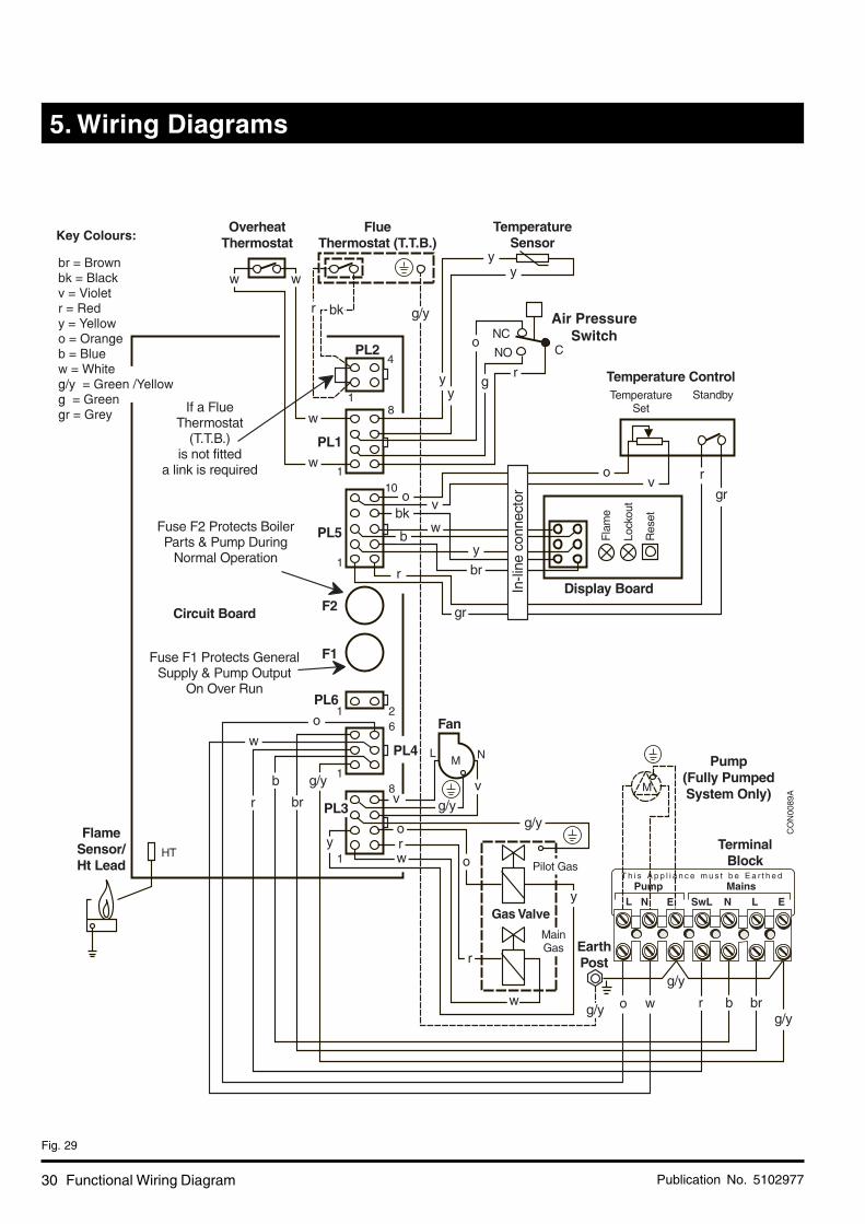
5. Wiring Diagrams
Functional Wiring Diagram
Fig. 29
Air PressureSwitch
CO
N00
89A

Publication No. 5102977 31
Fig. 30
Pictorial Wiring Diagram
CO
N00
82B
T.T.B. CFLModels Only

Publication No. 510297732 Fault Finding
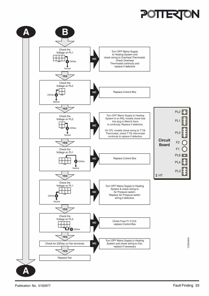
6. Fault Finding Guide
CO
N00
51C
ReplaceF2 fuse
with fuseof the
correct type
If Red LED is 'ON' and the Boiler fails to work check the following:Electrical Plugs (PL1 to PL6) are to remain connected to the Circuit Board for Fault Finding checks.
ALL Electrical Power to the Heating System OFF - NO External Call for Heat (Thermostat & Programmer OFF)Boiler Temperature Knob Set to'0' (Fully anti-clockwise 'click' OFF) - Gas & Water Connections Turned ONMain Supply Voltage is between 196Vac & 253Vac.
Publication No. 5102977 33Fault Finding
CO
N00
83A
Turn OFF Mains Supply to HeatingSystem & on RSL models check that
link plug is fitted & thereis continuity. Replace if defective.
On CFL models check wiring to T.T.B.Thermostat, check T.T.B. thermostat
continuity & replace if defective.

Publication No. 510297734 Fault Finding

Publication No. 5102977 35Fault Finding

Publication No. 510297736
7. Short List Of Spare Parts
Short List Spare Parts
Fig. 31
50-100Models
40Model
CON0060D
Publication No. 5102977 37Short List Spare Parts
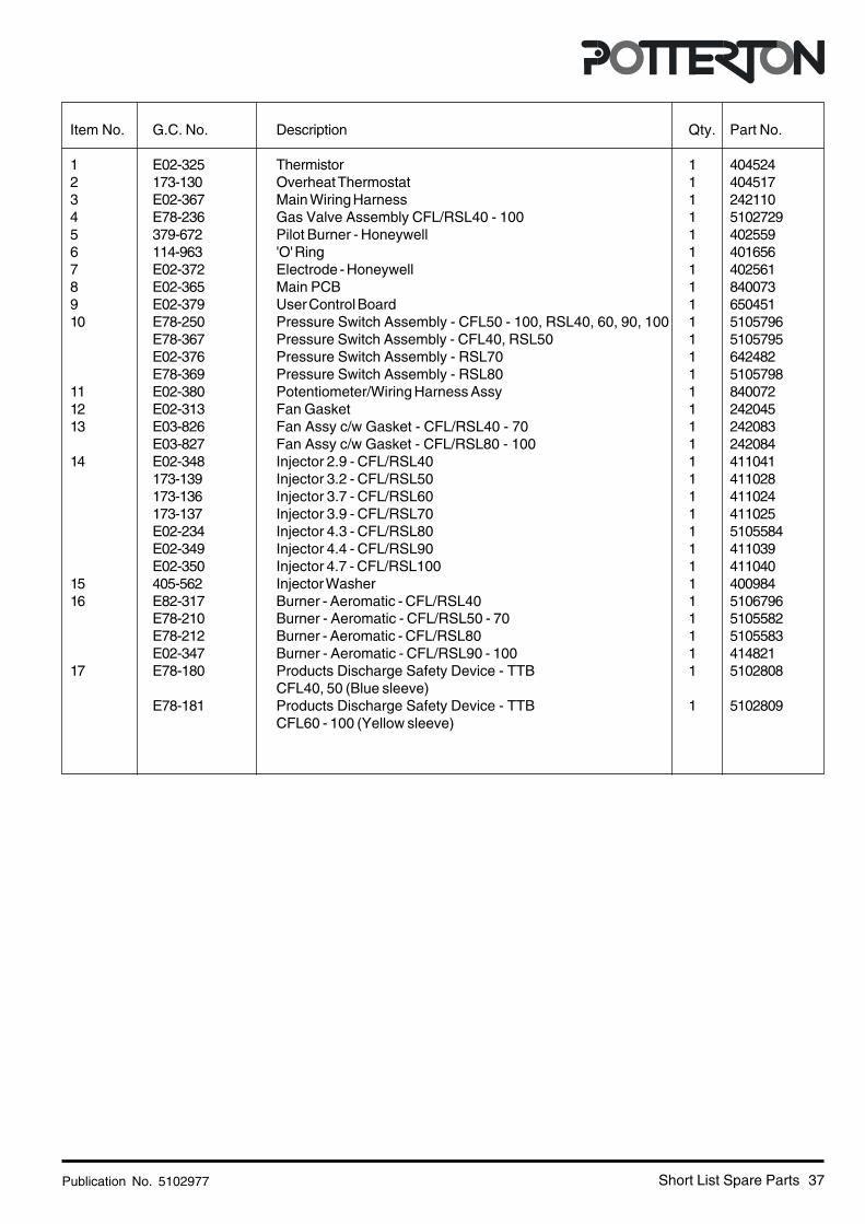
Item No. G.C. No. Description Qty. Part No.
1 E02-325 Thermistor 1 4045242 173-130 Overheat Thermostat 1 4045173 E02-367 Main Wiring Harness 1 2421104 E78-236 Gas Valve Assembly CFL/RSL40 - 100 1 51027295 379-672 Pilot Burner - Honeywell 1 4025596 114-963 'O' Ring 1 4016567 E02-372 Electrode - Honeywell 1 4025618 E02-365 Main PCB 1 8400739 E02-379 User Control Board 1 65045110 E78-250 Pressure Switch Assembly - CFL50 - 100, RSL40, 60, 90, 100 1 5105796
E78-367 Pressure Switch Assembly - CFL40, RSL50 1 5105795E02-376 Pressure Switch Assembly - RSL70 1 642482E78-369 Pressure Switch Assembly - RSL80 1 5105798
11 E02-380 Potentiometer/Wiring Harness Assy 1 84007212 E02-313 Fan Gasket 1 24204513 E03-826 Fan Assy c/w Gasket - CFL/RSL40 - 70 1 242083
E03-827 Fan Assy c/w Gasket - CFL/RSL80 - 100 1 24208414 E02-348 Injector 2.9 - CFL/RSL40 1 411041
173-139 Injector 3.2 - CFL/RSL50 1 411028173-136 Injector 3.7 - CFL/RSL60 1 411024173-137 Injector 3.9 - CFL/RSL70 1 411025E02-234 Injector 4.3 - CFL/RSL80 1 5105584E02-349 Injector 4.4 - CFL/RSL90 1 411039E02-350 Injector 4.7 - CFL/RSL100 1 411040
15 405-562 Injector Washer 1 40098416 E82-317 Burner - Aeromatic - CFL/RSL40 1 5106796
E78-210 Burner - Aeromatic - CFL/RSL50 - 70 1 5105582E78-212 Burner - Aeromatic - CFL/RSL80 1 5105583E02-347 Burner - Aeromatic - CFL/RSL90 - 100 1 414821
17 E78-180 Products Discharge Safety Device - TTB 1 5102808CFL40, 50 (Blue sleeve)
E78-181 Products Discharge Safety Device - TTB 1 5102809CFL60 - 100 (Yellow sleeve)
Publication No. 510297738
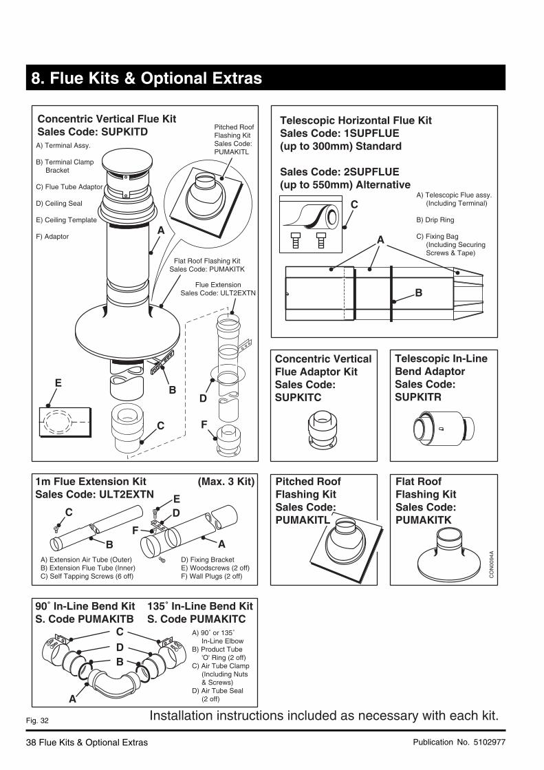
Concentric Vertical Flue KitSales Code: SUPKITDA) Terminal Assy.
B) Terminal Clamp Bracket
C) Flue Tube Adaptor
D) Ceiling Seal
E) Ceiling Template
F) Adaptor
Telescopic Horizontal Flue KitSales Code: 1SUPFLUE(up to 300mm) Standard
Sales Code: 2SUPFLUE(up to 550mm) Alternative
A) Telescopic Flue assy. (Including Terminal)
B) Drip Ring
C) Fixing Bag (Including Securing Screws & Tape)
Pitched RoofFlashing KitSales Code:PUMAKITL
Flat Roof Flashing KitSales Code: PUMAKITK
Flue ExtensionSales Code: ULT2EXTN
Installation instructions included as necessary with each kit.
A
C
A
B
BE
D
FC
1m Flue Extension KitSales Code: ULT2EXTN
(Max. 3 Kit)
A) Extension Air Tube (Outer)B) Extension Flue Tube (Inner)C) Self Tapping Screws (6 off)
Flat RoofFlashing KitSales Code:PUMAKITK
90˚ In-Line Bend KitS. Code PUMAKITB
A) 90˚ or 135˚ In-Line ElbowB) Product Tube 'O' Ring (2 off)C) Air Tube Clamp (Including Nuts & Screws)D) Air Tube Seal (2 off)
D) Fixing BracketE) Woodscrews (2 off)F) Wall Plugs (2 off)
A
ED
FB
Concentric VerticalFlue Adaptor KitSales Code:SUPKITC
BDC
A
135˚ In-Line Bend KitS. Code PUMAKITC
Min. Offset Flue KitSales Code: 3SUPKIT
A) Terminal ElbowB) Terminal AdaptorC) Terminal Assem.D) Drip RingE) Sealing TapeF) Screw PackG) Wall Template
F
E
G
AB
C
D
C
CO
N00
94A
Telescopic In-LineBend AdaptorSales Code:SUPKITR
Pitched RoofFlashing KitSales Code:PUMAKITL
8. Flue Kits & Optional Extras
Flue Kits & Optional Extras
Fig. 32
Publication No. 5102977 39Flue Kits & Optional Extras
Fig. 33
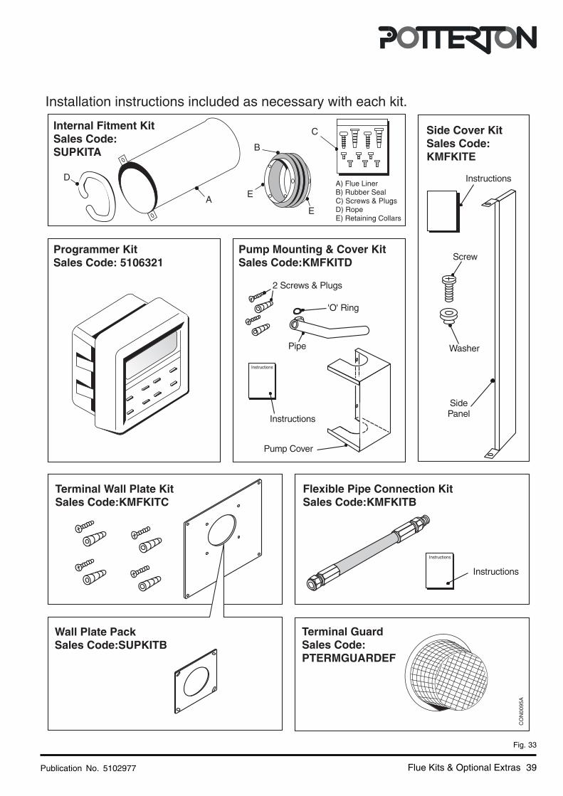
Installation instructions included as necessary with each kit.
CO
N00
95A

Baxi PottertonBrownedge Road, Bamber Bridge
Preston, LancashirePR5 6SN
www.potterton.co.uk
All descriptions and illustrations provided in this leaflet have been care-
fully prepared but we reserve the right to make changes and improve-
ments in our products which may affect the accuracy of the information
contained in this leaflet. All goods are sold subject to our standard
Conditions of Sale which are available on request.
* To aid continuous improvement and staff training, calls to this
line may be monitored or recorded.
���������������
���� �������������
����������
���� �������������
���������
���� �������������
���� ������������
���������������
���� �����������
Publication No. 5102977 - Iss. 03 (01/2002)