installer's guide to sip trunk integrations · installer's guide to sip trunk...
TRANSCRIPT

Installer's Guide to SIP Trunk Integrations www.incontact.com
Installer's Guide to SIP Trunk Integrations
2
Installer's Guide to SIP Trunk Integrations
• Version — This guide can be used with inContact WFO v5.5 or later.
• Revision — March 2016
• About inContact — inContact (NASDAQ: SAAS) is leader in cloud contact center software, helping organizations around the globe create customer and contact center employee experiences that are more personalized, more empowering and more engaging today, tomorrow and in the future. inContact focuses on continuous innovation and is the only provider to offer core contact center infrastructure, workforce optimization plus an enterprise-class telecommunications network for the most complete customer journey management. inContact offers customers a choice of deployment options. To learn more, visit www.inContact.com.
• Copyright — ©2016 inContact, Inc.
• Disclaimer — inContact reserves the right to update or append this document, as needed.
• Contact — Send suggestions or corrections regarding this guide to [email protected].
Installer's Guide to SIP Trunk Integrations
3
Table of Contents
Introduction ............................................................................................ 5
Audience................................................................................................................................5
Goals ......................................................................................................................................5
Assumptions .........................................................................................................................5
Need-to-Knows .....................................................................................................................6
SIP Trunk Recording Integrations ............................................................ 7
SIP Trunk Recording Integration Overview ........................................................................7
Customer Responsibilities ..................................................................................................8
Recording Integration Basics ................................................................... 9
Voice Boards Overview ........................................................................................................9
Create a Voice Board......................................................................................................... 10
Configure a Voice Board ................................................................................................... 11
Configure Channels ........................................................................................................... 11
CTI Core Overview ............................................................................................................. 12
Create a CTI Core ............................................................................................................... 12
Configure a CTI Core ......................................................................................................... 13
Increase the RTP Port Limit (optional) .................................................................................... 13
Specify Related Components ........................................................................................... 14
Add a CTI Module .............................................................................................................. 15
Configure CTI Monitors ............................................................................................................. 15
Configure Monitor Request Timeout (Optional)...................................................................... 16
Register the CTI Core as a Windows Service ................................................................. 16
Installer's Guide to SIP Trunk Integrations
4
Add the CTI Core to the Service Manager ....................................................................... 18
Install the Channel Script ................................................................................................. 18
Recording Integration Specifics ............................................................. 19
Install WinPcap .................................................................................................................. 19
Identify Listening Interface ID .......................................................................................... 19
Specific Settings for SIP Trunk Recording Integrations ............................................... 20
Voice Board Hardware Type ..................................................................................................... 20
Channel Settings ........................................................................................................................ 20
CTI Core Settings ....................................................................................................................... 20
Related Components ................................................................................................................. 20
CTI Module Settings (SIP Recorder) ........................................................................................ 20
Appendix: Integration Setting Definitions .............................................. 22
Voice Board Setting Definitions ....................................................................................... 22
Channel Configuration Setting Definitions ..................................................................... 32
Channel Assignment Settings Definitions............................................................................... 34
CTI Core Setting Definitions ............................................................................................. 35
Document Revision History ................................................................... 39

Installer's Guide to SIP Trunk Integrations
5
Introduction
Audience
This document is written for installation and support engineers at both inContact and our partner organizations who work with installing inContact WFO. Readers should have a basic level of familiarity with IP telephony, SIP trunks, general networking, the Windows operating system, and inContact WFO.
Goals
The goal of this document is to provide knowledge, reference, and procedural information necessary to configure inContact WFO for audio traffic recording and metadata collection using SIP trunk integration.
This document is NOT intended as a specific system or network design document. If further clarification is needed, consult the inContact WFO installation or project team, the customer, and/or the customer's telephony vendor.
Assumptions
This document assumes the inContact WFO team has:
• Confirmed the PBX hardware and software are working correctly.
• Obtained any necessary PBX and LAN information from the project team and/or the customer.
• Installed inContact WFO correctly. For more information on base installation, refer to the inContact WFO Installation Guide for the desired version of the software.
• Created inContact WFO recording schedules. Schedules can be created later and then associated with the CTI Core if necessary. No calls will record until schedules are created.
Installer's Guide to SIP Trunk Integrations
6
Need-to-Knows
To facilitate ease of use, this document takes advantage of PDF bookmarks. By opening the bookmark pane, you can easily jump directly to a specific integration. You can also use the bookmarks to return to the integration specifics after completing a procedure located in a different section of the guide.
To expand and collapse the bookmark pane, click on the bookmark icon on the left side of the document window.
This integration provides a means of audio capture only; if a CTI source will be leveraged for call control and metadata, additional steps may be required.
This integration supports live monitoring capability, can be used with inContact WFO Screen Recording, and should work with any standard SIP trunk. It has been tested with Cisco Unified Communications Manager and inContact Cloud PBX.
Additional information and procedures for configuring the customer environment can be found in the inContact WFO Customer Guide to SIP Trunk Integrations.
Installer's Guide to SIP Trunk Integrations
7
SIP Trunk Recording Integrations
SIP Trunk Recording Integration Overview
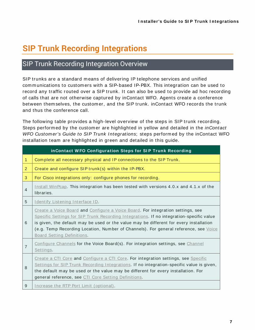
SIP trunks are a standard means of delivering IP telephone services and unified communications to customers with a SIP-based IP-PBX. This integration can be used to record any traffic routed over a SIP trunk. It can also be used to provide ad hoc recording of calls that are not otherwise captured by inContact WFO. Agents create a conference between themselves, the customer, and the SIP trunk. inContact WFO records the trunk and thus the conference call.
The following table provides a high-level overview of the steps in SIP trunk recording. Steps performed by the customer are highlighted in yellow and detailed in the inContact WFO Customer's Guide to SIP Trunk Integrations; steps performed by the inContact WFO installation team are highlighted in green and detailed in this guide.
inContact WFO Configuration Steps for SIP Trunk Recording
1 Complete all necessary physical and IP connections to the SIP Trunk.
2 Create and configure SIP trunk(s) within the IP-PBX.
3 For Cisco integrations only: configure phones for recording.
4 Install WinPcap. This integration has been tested with versions 4.0.x and 4.1.x of the libraries.
5 Identify Listening Interface ID.
6
Create a Voice Board and Configure a Voice Board. For integration settings, see Specific Settings for SIP Trunk Recording Integrations. If no integration-specific value is given, the default may be used or the value may be different for every installation (e.g. Temp Recording Location, Number of Channels). For general reference, see Voice Board Setting Definitions.
7 Configure Channels for the Voice Board(s). For integration settings, see Channel Settings.
8
Create a CTI Core and Configure a CTI Core. For integration settings, see Specific Settings for SIP Trunk Recording Integrations. If no integration-specific value is given, the default may be used or the value may be different for every installation. For general reference, see CTI Core Setting Definitions.
9 Increase the RTP Port Limit (optional).
Installer's Guide to SIP Trunk Integrations
8
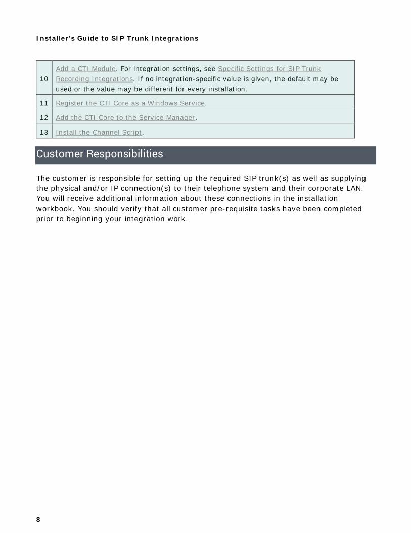
10 Add a CTI Module. For integration settings, see Specific Settings for SIP Trunk Recording Integrations. If no integration-specific value is given, the default may be used or the value may be different for every installation.
11 Register the CTI Core as a Windows Service.
12 Add the CTI Core to the Service Manager.
13 Install the Channel Script.
Customer Responsibilities
The customer is responsible for setting up the required SIP trunk(s) as well as supplying the physical and/or IP connection(s) to their telephone system and their corporate LAN. You will receive additional information about these connections in the installation workbook. You should verify that all customer pre-requisite tasks have been completed prior to beginning your integration work.
Installer's Guide to SIP Trunk Integrations
9
Recording Integration Basics Recording in inContact WFO involves two primary software components:
• Voice Boards: control how inContact WFO acquires audio. This component provides what inContact WFO is to record. You will need to configure at least one Voice Board for most integrations.
• CTI Core: integrates with the PBX/ACD and makes call recording decisions based on customer-defined Schedules. This component tells inContact WFO when to record. You will need to configure at least one CTI Core for most integrations.
This section provides basic knowledge and procedures for recording integrations. If you are already familiar with the basic procedures for configuring a recording integration in inContact WFO, you may wish to go directly to the Recording Integration Specifics section.
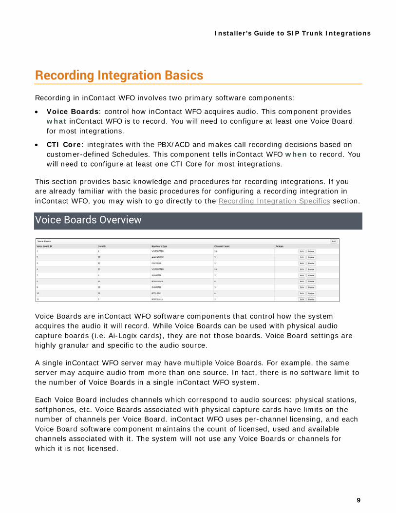
Voice Boards Overview
Voice Boards are inContact WFO software components that control how the system acquires the audio it will record. While Voice Boards can be used with physical audio capture boards (i.e. Ai-Logix cards), they are not those boards. Voice Board settings are highly granular and specific to the audio source.
A single inContact WFO server may have multiple Voice Boards. For example, the same server may acquire audio from more than one source. In fact, there is no software limit to the number of Voice Boards in a single inContact WFO system.
Each Voice Board includes channels which correspond to audio sources: physical stations, softphones, etc. Voice Boards associated with physical capture cards have limits on the number of channels per Voice Board. inContact WFO uses per-channel licensing, and each Voice Board software component maintains the count of licensed, used and available channels associated with it. The system will not use any Voice Boards or channels for which it is not licensed.
Installer's Guide to SIP Trunk Integrations
10
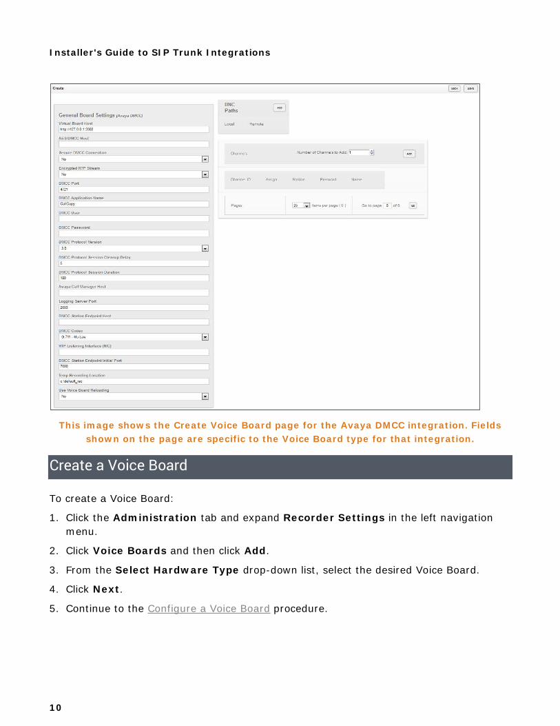
This image shows the Create Voice Board page for the Avaya DMCC integration. Fields shown on the page are specific to the Voice Board type for that integration.
Create a Voice Board
To create a Voice Board:
1. Click the Administration tab and expand Recorder Settings in the left navigation menu.
2. Click Voice Boards and then click Add.
3. From the Select Hardware Type drop-down list, select the desired Voice Board.
4. Click Next.
5. Continue to the Configure a Voice Board procedure.
Installer's Guide to SIP Trunk Integrations
11
Configure a Voice Board
This procedure can be followed as part of the initial Voice Board set-up, or to edit Voice Board settings at a later time. To configure a Voice Board (if you are configuring a Voice Board you just created, begin with step 4):
1. Click the Administration tab and expand Recorder Settings in the left navigation menu.
2. Click Voice Boards.
3. Click the Edit icon for the Voice Board you wish to configure.
4. Configure the Voice Board settings for the specific integration.
5. Follow the steps in the Configure Channels procedure if needed, or click Save.
When you are finished, you can click Back to return to the Voice Boards list, or simply navigate to another part of the Web Portal.
Configure Channels
Channel configuration associates the licensed software channels on the Voice Board with the audio sources that will be recorded. This procedure can be followed as part of the initial Voice Board set-up, or to edit Channel settings at a later time. To configure a Channel (if you are configuring Channels for a Voice Board you just created, begin with step 4):
1. Click the Administration tab and expand Recorder Settings in the left navigation menu.
2. Click Voice Boards.
3. Click the Edit icon for the Voice Board you wish to configure.
4. Under Channel Configuration, configure the channel settings for this installation.
5. Click Save.
When you are finished, you can click Back to return to the Voice Boards list, or simply navigate to another part of the Web Portal.
Installer's Guide to SIP Trunk Integrations
12
CTI Core Overview
CTI Core is the software component that provides the PBX/ACD integration and makes call recording decisions based on business logic configured in the Scheduler. CTI Core is also responsible for recording the raw audio files used for playback. It handles back-end communication for CTI messaging, CTI scripting, CallStarts/Stops/Updates, RecordStarts/Stops and PlaybackStarts/Stops.
inContact WFO supports multiple Cores, both on an individual inContact WFO server and within a multi-server inContact WFO system. Different Cores may be used for different integrations, to provide for failover recording as part of continuity and recovery planning, or for implementations with different geographic sites. The Core topology will be created during the discovery process by the inContact WFO Sales Engineer.
Integration settings in inContact WFO take effect when the CTI Core is started either manually or when the host machine starts. The Core must be restarted if:
• A Voice Board is changed, added, or removed.
• A Core setting is changed (except for adding, removing, or changing Schedules).
• A CTI module setting is changed or a module is added or removed.
Changes (for example, channel additions, removals, or settings changes) to monitors listed on CTI module pages do not require a restart. Core uses the Monitor Reload Frequency to know how often to check for new monitors.
Create a CTI Core
To create a CTI Core:
1. Click the Administration tab and expand Recorder Settings in the left navigation menu.
2. Click CTI Cores and then click Add Core.
3. Continue to the Configure a CTI Core procedure.
Installer's Guide to SIP Trunk Integrations
13
Configure a CTI Core
This procedure can be followed as part of the initial CTI Core set-up, or to edit CTI Core settings at a later time. To configure a CTI Core (if you are configuring a CTI Core you just created, begin with step 3):
1. Click the Administration tab and expand Recorder Settings in the left navigation menu.
2. Click CTI Cores.
3. Click the Edit icon for the CTI Core you wish to configure.
4. Configure the CTI Core settings for the specific integration.
5. Follow the steps in the Increase the RTP Port Limit (optional) task if needed.
6. Follow the steps in the Add a CTI Module procedure if needed.
7. Click Save.
Increase the RTP Port Limit (optional)
This procedure is required only if your configuration includes a Voice Board with 500 or more channels, and the CTI Core version is x.x.x.3263 or higher.
Beginning with version x.x.x.3263, CTI Core uses four ports for audio. This requires an adjustment to the core.ini file for some deployments, as noted above. To increase the RTP port limit:
1. On the inContact WFO server, browse to C:\Program Files (x86)\CallCopy\Recorder.
2. Find and open the CtiCore folder for the Core associated with the 500+ channel Voice Board.
3. Open (or create, if it is not there already) the file cc_cticore.ini. The INI filename should always match the name of the executable it configures.
4. Under the section [rtp], add the following value:
portPoolLength=
Specifies the number of ports available for RTP packets. This value should equal the number of Voice Board channels x4 (for example, 2600 for a 650-channel Voice Board).
5. Save the INI file.
Installer's Guide to SIP Trunk Integrations
14
Specify Related Components
This procedure can be followed as part of the initial CTI Core set-up, or to make changes to the Core at a later time. To specify components related to this CTI Core (if you are configuring a CTI Core you just created, begin with step 4):
1. Click the Administration tab and expand Recorder Settings in the left navigation menu.
2. Click CTI Cores.
3. Click the Edit icon for the CTI Core you wish to configure.
4. From the drop-down list, select the desired Voice Board and click the plus-sign icon to add it to Related Boards.
5. From the drop-down list, select any associated Cores that will be controlled by the Core you are configuring, and click the plus-sign icon to add them to Related Core(s).
6. From the drop-down list, select any schedules that should be associated with this Core and click the plus-sign icon to add them to the Related Schedules list. If you do not associate any schedules, the Core will use all schedules created in inContact WFO.
7. Return to the Configure a CTI Core procedure or click Save.
Installer's Guide to SIP Trunk Integrations
15
Add a CTI Module
Some integrations require that one or more CTI Modules be added to the CTI Core. This procedure can be followed as part of the initial CTI Core set-up, or to make changes to the Core's CTI Module at a later date (skip steps 4 and 5). To add a CTI Module (if you are adding the module as part of initial Core configuration, begin with step 4):
1. Click the Administration tab and expand Recorder Settings in the left navigation menu.
2. Click CTI Cores.
3. Click the Edit icon for the CTI Core you wish to configure.
4. From the drop-down list, select the desired CTI Module.
5. Click Add CTI Module.
6. Click the Edit icon for the CTI Module you wish to configure.
7. Configure the CTI Module settings for the specific integration.
8. Configure CTI Monitors if needed.
9. Click Save.
10.Return to the Configure a CTI Core procedure or click Save.
Configure CTI Monitors
Some CTI Modules require a list of devices to monitor. Any phone or device that should be monitored must be configured in this list. You can also establish Prefix and Postfix settings for all monitors, which can be used to distinguish extensions by areas or groups.
To configure devices for monitoring:
1. Select the desired choice from the Monitor Type list.
2. Enter the phone extensions for recording in the Monitor Values field as a single extension (e.g. ‘1234’), multiple extensions in a comma separated list (e.g. ‘1234,2345,4321’) or a range of extensions using a hyphen (e.g. 2300-2400).
3. Enter Prefix and/or Postfix settings if desired.
4. Click the Add icon to add the monitor types to the list.
5. Click Save.
To delete single items from the Monitor list:
• Click the Delete icon beside the item.
To delete multiple items from the list:
Installer's Guide to SIP Trunk Integrations
16
• Enter a range of items in the Monitor Values field and click the Delete icon.
To filter the displayed list of Monitor Types:
• Select a value from the Filter Monitors drop-down list and click the Filter icon.
Configure Monitor Request Timeout (Optional)
Some CTI Modules can cancel monitor registration requests if a response is not received before a timeout threshold is reached. The default threshold is 10 seconds, but you can configure a different timeout threshold if desired.
Setting the timeout to 0 does not disable this setting, but instead sets the request to timeout immediately.
To configure a monitor request timeout threshold:
1. On the inContact WFO server, browse to C:\Program Files (x86)\CallCopy\Recorder.
2. Find and open the CtiCore folder that corresponds to the Core with the desired module attached.
3. Open (or create, if it is not there already) the file cc_cticore.ini. The INI filename should always match the name of the executable it configures.
4. Under the section [cc_AvayaTSAPIFx], add the following value:
monitortimeout= Time to wait, in seconds, before timing out the request.
5. Save the INI file.
Register the CTI Core as a Windows Service
The CTI Core must be registered as a service on its host server. If you are installing multiple Cores on a server, you will need to assign an instance number to each. inContact WFO recommends matching the instance number to the unique "ident" number that inContact WFO assigned to the Core when you created it. The number is displayed in the # column of the CTI Cores List. To see this list:
• Click the Administration tab, expand Recorder Settings in the left navigation menu, and then click CTI Cores.
Registering the CTI Core as a Windows Service is done in the command line using these common parameters:
Installer's Guide to SIP Trunk Integrations
17
• -svcinst: Used to install the instance of a service. If you install multiple instances, the –instance parameter must be used to specify which instance is being added/removed. To uninstall, use –svcuninst.
• -instance #: Assigns an instance number to a service. This is used when the same service is installed and run multiple times on the same server. This command line argument is only usable when you install a module as a service.
• -autostart: Sets the service to start up automatically when the server boots. This is a Windows-level setting and works independently of the restart settings in the inContact WFO Service Manager.
• -options: Allows you to specify further settings for the service. The most common use is to specify the identifier, explained below.
• "-[Identifier Name]=X": Used with the –options parameter. Specifies the identifier to query for settings from the database. X should be an integer and a valid reference to an entry within the relevant table. The specific format of the identifier depends on the service being configured. In this case, X would be the number assigned to this Core by inContact WFO, as shown in the CTI Cores List.
To register the CTI Core:
1. Open a Command Prompt window.
2. Change to the Recorder directory.
3. Run the following command:
Cticore\cc_cticore.exe –svcinst –instance 1 –autostart –options "-core=1"
Installer's Guide to SIP Trunk Integrations
18
Add the CTI Core to the Service Manager
To add the CTI Core to the Service Manager:
1. Click Administration tab and expand Tools in the left navigation menu.
2. Click Service Manager.
3. Expand the Server Node on which the Core is running.
4. Click Add Application.
5. Under Application, enter cc_cticore.exe #, where # is the instance number you used to Register the CTI Core as a Windows Service.
6. Set Auto-Restart to Yes.
7. Click Save and, if the Core's status is not Running, click the Start button for that Core.
Install the Channel Script
inContact WFO uses a channel logic script in order to process CTI events into recordings. The channel script determines exactly which source events are processed as inContact WFO events, including recording start/stop triggers, call detail information, etc. Channel scripts are written in C# and stored in ‘.cs’ files.
Default scripts for integrations can be obtained from the inContact WFO inContact WFO installation team. To install the channel script:
1. Open Windows Explorer on the server running the CTI Core.
2. Navigate to Recorder\CTICore\channelscript\. If this folder does not exist, you will need to create it.
3. Copy the channel script into the folder.
If you have multiple CTI Cores, you will need to repeat this procedure with the correct channel script for each Core.

Installer's Guide to SIP Trunk Integrations
19
Recording Integration Specifics This section outlines procedures for and provides settings specific to this integration. If you are unfamiliar with the basic procedures for configuring a recording integration in inContact WFO, refer to the Recording Integration Basics section.
Install WinPcap
WinPcap is an open-source tool used in inContact WFO VoIP integrations. It enables applications to bypass the protocol stack when capturing and transmitting packets, and also provides useful diagnostic and filtering tools. You can get the installation files for WinPcap libraries from the inContact WFO installation team or from the WinPCAP website.
Identify Listening Interface ID
Wireshark can also be used for this task. For more information, visit the Wireshark website.
To properly capture audio from the network interface, you must obtain the Listening Interface ID for the NIC.
To use the inContact WFO Network Interface Browser utility to obtain this ID:
1. Navigate to the Recorder directory on the inContact WFO server.
2. Launch cc_interfaceBrowser.exe.
3. Select the network adapter you will use for the VoIP traffic.
4. Note the Listening Interface (NIC) value for use later in the configuration.
Installer's Guide to SIP Trunk Integrations
20
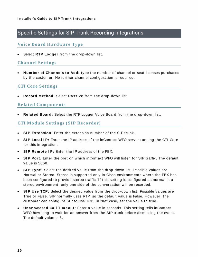
Specific Settings for SIP Trunk Recording Integrations
Voice Board Hardware Type
• Select RTP Logger from the drop-down list.
Channel Settings
• Number of Channels to Add: type the number of channel or seat licenses purchased by the customer. No further channel configuration is required.
CTI Core Settings
• Record Method: Select Passive from the drop-down list.
Related Components
• Related Board: Select the RTP Logger Voice Board from the drop-down list.
CTI Module Settings (SIP Recorder)
• SIP Extension: Enter the extension number of the SIP trunk.
• SIP Local IP: Enter the IP address of the inContact WFO server running the CTI Core for this integration.
• SIP Remote IP: Enter the IP address of the PBX.
• SIP Port: Enter the port on which inContact WFO will listen for SIP traffic. The default value is 5060.
• SIP Type: Select the desired value from the drop-down list. Possible values are Normal or Stereo. Stereo is supported only in Cisco environments where the PBX has been configured to provide stereo traffic. If this setting is configured as normal in a stereo environment, only one side of the conversation will be recorded.
• SIP Use TCP: Select the desired value from the drop-down list. Possible values are True or False. SIP normally uses RTP, so the default value is False. However, the customer can configure SIP to use TCP. In that case, set the value to true.
• Unanswered Call Timeout: Enter a value in seconds. This setting tells inContact WFO how long to wait for an answer from the SIP trunk before dismissing the event. The default value is 5.
Installer's Guide to SIP Trunk Integrations
21
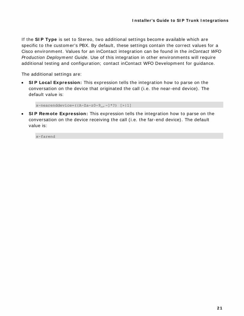
If the SIP Type is set to Stereo, two additional settings become available which are specific to the customer's PBX. By default, these settings contain the correct values for a Cisco environment. Values for an inContact integration can be found in the inContact WFO Production Deployment Guide. Use of this integration in other environments will require additional testing and configuration; contact inContact WFO Development for guidance.
The additional settings are:
• SIP Local Expression: This expression tells the integration how to parse on the conversation on the device that originated the call (i.e. the near-end device). The default value is:
x-nearenddevice=({A-Za-z0-9_,-]*?) [>|1]
• SIP Remote Expression: This expression tells the integration how to parse on the conversation on the device receiving the call (i.e. the far-end device). The default value is:
x-farend
Installer's Guide to SIP Trunk Integrations
22
Appendix: Integration Setting Definitions
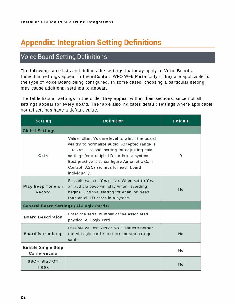
Voice Board Setting Definitions
The following table lists and defines the settings that may apply to Voice Boards. Individual settings appear in the inContact WFO Web Portal only if they are applicable to the type of Voice Board being configured. In some cases, choosing a particular setting may cause additional settings to appear.
The table lists all settings in the order they appear within their sections, since not all settings appear for every board. The table also indicates default settings where applicable; not all settings have a default value.
Setting Definition Default
Global Settings
Gain
Value: dBm. Volume level to which the board will try to normalize audio. Accepted range is 1 to -45. Optional setting for adjusting gain settings for multiple LD cards in a system. Best practice is to configure Automatic Gain Control (AGC) settings for each board individually.
0
Play Beep Tone on Record
Possible values: Yes or No. When set to Yes, an audible beep will play when recording begins. Optional setting for enabling beep tone on all LD cards in a system.
No
General Board Settings (Ai-Logix Cards)
Board Description Enter the serial number of the associated physical Ai-Logix card.
Board is trunk tap Possible values: Yes or No. Defines whether the Ai-Logix card is a trunk- or station-tap card.
No
Enable Single Step Conferencing
No
SSC – Stay Off Hook
No
Installer's Guide to SIP Trunk Integrations
23
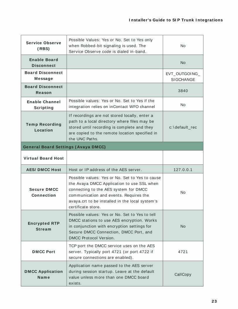
Service Observe (RBS)
Possible Values: Yes or No. Set to Yes only when Robbed-bit signaling is used. The Service Observe code is dialed in-band.
No
Enable Board Disconnect
No
Board Disconnect Message
EVT_OUTGOING_ SIGCHANGE
Board Disconnect Reason 3840
Enable Channel Scripting
Possible values: Yes or No. Set to Yes if the integration relies on inContact WFO channel
i
No
Temp Recording Location
If recordings are not stored locally, enter a path to a local directory where files may be stored until recording is complete and they are copied to the remote location specified in the UNC Paths.
c:\default_rec
General Board Settings (Avaya DMCC)
Virtual Board Host
AES/DMCC Host Host or IP address of the AES server. 127.0.0.1
Secure DMCC Connection
Possible values: Yes or No. Set to Yes to cause the Avaya DMCC Application to use SSL when connecting to the AES system for DMCC communication and events. Requires the avaya.crt to be installed in the local system’s certificate store.
No
Encrypted RTP Stream
Possible values: Yes or No. Set to Yes to tell DMCC stations to use AES encryption. Works in conjunction with encryption settings for Secure DMCC Connection, DMCC Port, and DMCC Protocol Version.
No
DMCC Port TCP port the DMCC service uses on the AES server. Typically port 4721 (or port 4722 if secure connections are enabled).
4721
DMCC Application Name
Application name passed to the AES server during session startup. Leave at the default value unless more than one DMCC board exists.
CallCopy
Installer's Guide to SIP Trunk Integrations
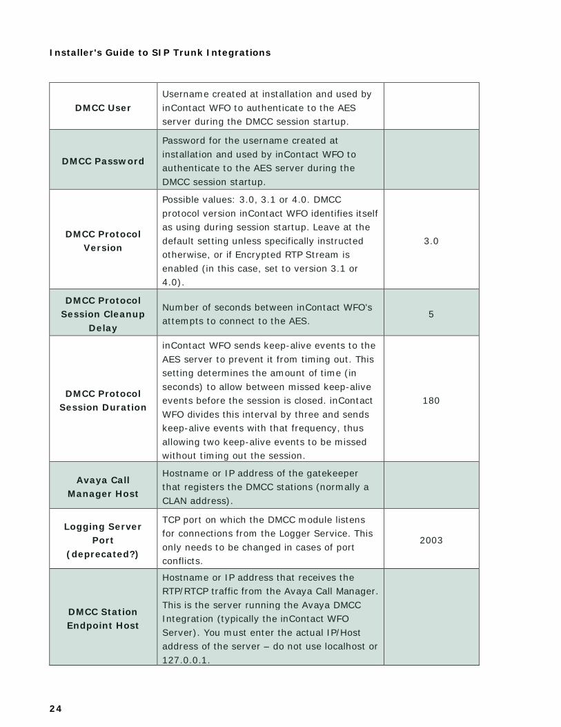
24
DMCC User Username created at installation and used by inContact WFO to authenticate to the AES server during the DMCC session startup.
DMCC Password
Password for the username created at installation and used by inContact WFO to authenticate to the AES server during the DMCC session startup.
DMCC Protocol Version
Possible values: 3.0, 3.1 or 4.0. DMCC protocol version inContact WFO identifies itself as using during session startup. Leave at the default setting unless specifically instructed otherwise, or if Encrypted RTP Stream is enabled (in this case, set to version 3.1 or 4.0).
3.0
DMCC Protocol Session Cleanup
Delay
Number of seconds between inContact WFO's attempts to connect to the AES.
5
DMCC Protocol Session Duration
inContact WFO sends keep-alive events to the AES server to prevent it from timing out. This setting determines the amount of time (in seconds) to allow between missed keep-alive events before the session is closed. inContact WFO divides this interval by three and sends keep-alive events with that frequency, thus allowing two keep-alive events to be missed without timing out the session.
180
Avaya Call Manager Host
Hostname or IP address of the gatekeeper that registers the DMCC stations (normally a CLAN address).
Logging Server Port
(deprecated?)
TCP port on which the DMCC module listens for connections from the Logger Service. This only needs to be changed in cases of port conflicts.
2003
DMCC Station Endpoint Host
Hostname or IP address that receives the RTP/RTCP traffic from the Avaya Call Manager. This is the server running the Avaya DMCC Integration (typically the inContact WFO Server). You must enter the actual IP/Host address of the server – do not use localhost or 127.0.0.1.
Installer's Guide to SIP Trunk Integrations
25
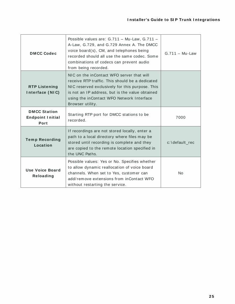
DMCC Codec
Possible values are: G.711 – Mu-Law, G.711 – A-Law, G.729, and G.729 Annex A. The DMCC voice board(s), CM, and telephones being recorded should all use the same codec. Some combinations of codecs can prevent audio from being recorded.
G.711 – Mu-Law
RTP Listening Interface (NIC)
NIC on the inContact WFO server that will receive RTP traffic. This should be a dedicated NIC reserved exclusively for this purpose. This is not an IP address, but is the value obtained using the inContact WFO Network Interface Browser utility.
DMCC Station Endpoint Initial
Port
Starting RTP port for DMCC stations to be recorded.
7000
Temp Recording Location
If recordings are not stored locally, enter a path to a local directory where files may be stored until recording is complete and they are copied to the remote location specified in the UNC Paths.
c:\default_rec
Use Voice Board Reloading
Possible values: Yes or No. Specifies whether to allow dynamic reallocation of voice board channels. When set to Yes, customer can add/remove extensions from inContact WFO without restarting the service.
No

Installer's Guide to SIP Trunk Integrations
26
General Board Settings (Loopback)
Board is trunk tap Possible values: Yes or No. Defines whether the Ai-Logix card is a trunk- or station-tap card.
No
Enable Single Step Conferencing
Possible Values: Yes or No. When set to Yes, inContact WFO acquires audio by establishing a conference call between the agent, the caller and recording channel.
No
General Board Settings (Nortel MLS)
Virtual Board Host http://127.0.0.1:2002
Logging Server Port
(deprecated?)
TCP port on which the DMCC module listens for connections from the Logger Service. This only needs to be changed in cases of port conflicts.
2003
Recording IP
Enter the IP address for the NIC on the inContact WFO server that will receive RTP traffic. This should be a dedicated NIC reserved exclusively for this purpose.
RTP Listening Interface (NIC)
NIC on the inContact WFO server that will receive RTP traffic. This should be a dedicated NIC reserved exclusively for this purpose. This is not an IP address, but is the value obtained using the Uptivity Network Interface Browser utility.
RTP Endpoint Initial Port
The starting UDP port inContact WFO uses to receive RTP for recording.
7000
Generate Warning Tone
Possible Values: Yes or No. Set to Yes if a recording warning tone is used.
No
Temp Recording Location
If recordings are not stored locally, enter a path to a local directory where files may be stored until recording is complete and they are copied to the remote location specified in the UNC Paths.
c:\default_rec
Installer's Guide to SIP Trunk Integrations
27
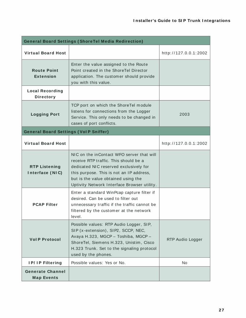
General Board Settings (ShoreTel Media Redirection)
Virtual Board Host http://127.0.0.1:2002
Route Point Extension
Enter the value assigned to the Route Point created in the ShoreTel Director application. The customer should provide you with this value.
Local Recording Directory
Logging Port
TCP port on which the ShoreTel module listens for connections from the Logger Service. This only needs to be changed in cases of port conflicts.
2003
General Board Settings (VoIP Sniffer)
Virtual Board Host http://127.0.0.1:2002
RTP Listening Interface (NIC)
NIC on the inContact WFO server that will receive RTP traffic. This should be a dedicated NIC reserved exclusively for this purpose. This is not an IP address, but is the value obtained using the Uptivity Network Interface Browser utility.
PCAP Filter
Enter a standard WinPcap capture filter if desired. Can be used to filter out unnecessary traffic if the traffic cannot be filtered by the customer at the network level.
VoIP Protocol
Possible values: RTP Audio Logger, SIP, SIP (x-extension), SIP2, SCCP, NEC, Avaya H.323, MGCP – Toshiba, MGCP – ShoreTel, Siemens H.323, Unistim, Cisco H.323 Trunk. Set to the signaling protocol used by the phones.
RTP Audio Logger
IP/IP Filtering Possible values: Yes or No. No
Generate Channel Map Events
Installer's Guide to SIP Trunk Integrations
28
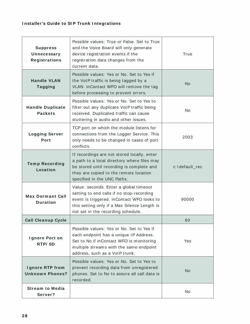
Suppress Unnecessary Registrations
Possible values: True or False. Set to True and the Voice Board will only generate device registration events if the registration data changes from the current data.
True
Handle VLAN Tagging
Possible values: Yes or No. Set to Yes if the VoIP traffic is being tagged by a VLAN. inContact WFO will remove the tag before processing to prevent errors.
No
Handle Duplicate Packets
Possible values: Yes or No. Set to Yes to filter out any duplicate VoIP traffic being received. Duplicated traffic can cause stuttering in audio and other issues.
No
Logging Server Port
TCP port on which the module listens for connections from the Logger Service. This only needs to be changed in cases of port conflicts.
2003
Temp Recording Location
If recordings are not stored locally, enter a path to a local directory where files may be stored until recording is complete and they are copied to the remote location specified in the UNC Paths.
c:\default_rec
Max Dormant Call Duration
Value: seconds. Enter a global timeout setting to end calls if no stop-recording event is triggered. inContact WFO looks to this setting only if a Max Silence Length is not set in the recording schedule.
90000
Call Cleanup Cycle 60
Ignore Port on RTP/SD
Possible values: Yes or No. Set to Yes if each endpoint has a unique IP Address. Set to No if inContact WFO is monitoring multiple streams with the same endpoint address, such as a VoIP trunk.
Yes
Ignore RTP from Unknown Phones?
Possible values: Yes or No. Set to Yes to prevent recording data from unregistered phones. Set to No to assure all call data is recorded.
No
Stream to Media Server?
No
Installer's Guide to SIP Trunk Integrations
29
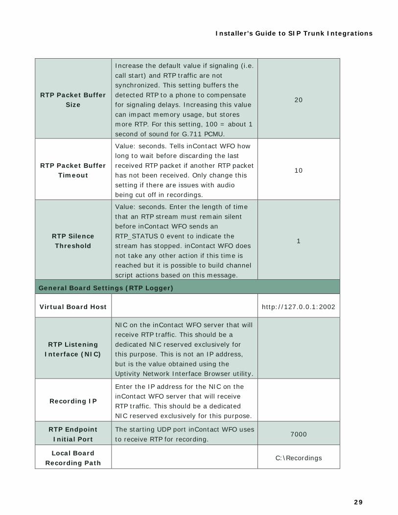
RTP Packet Buffer Size
Increase the default value if signaling (i.e. call start) and RTP traffic are not synchronized. This setting buffers the detected RTP to a phone to compensate for signaling delays. Increasing this value can impact memory usage, but stores more RTP. For this setting, 100 = about 1 second of sound for G.711 PCMU.
20
RTP Packet Buffer Timeout
Value: seconds. Tells inContact WFO how long to wait before discarding the last received RTP packet if another RTP packet has not been received. Only change this setting if there are issues with audio being cut off in recordings.
10
RTP Silence Threshold
Value: seconds. Enter the length of time that an RTP stream must remain silent before inContact WFO sends an RTP_STATUS 0 event to indicate the stream has stopped. inContact WFO does not take any other action if this time is reached but it is possible to build channel script actions based on this message.
1
General Board Settings (RTP Logger)
Virtual Board Host http://127.0.0.1:2002
RTP Listening Interface (NIC)
NIC on the inContact WFO server that will receive RTP traffic. This should be a dedicated NIC reserved exclusively for this purpose. This is not an IP address, but is the value obtained using the Uptivity Network Interface Browser utility.
Recording IP
Enter the IP address for the NIC on the inContact WFO server that will receive RTP traffic. This should be a dedicated NIC reserved exclusively for this purpose.
RTP Endpoint Initial Port
The starting UDP port inContact WFO uses to receive RTP for recording.
7000
Local Board Recording Path
C:\Recordings
Installer's Guide to SIP Trunk Integrations
30
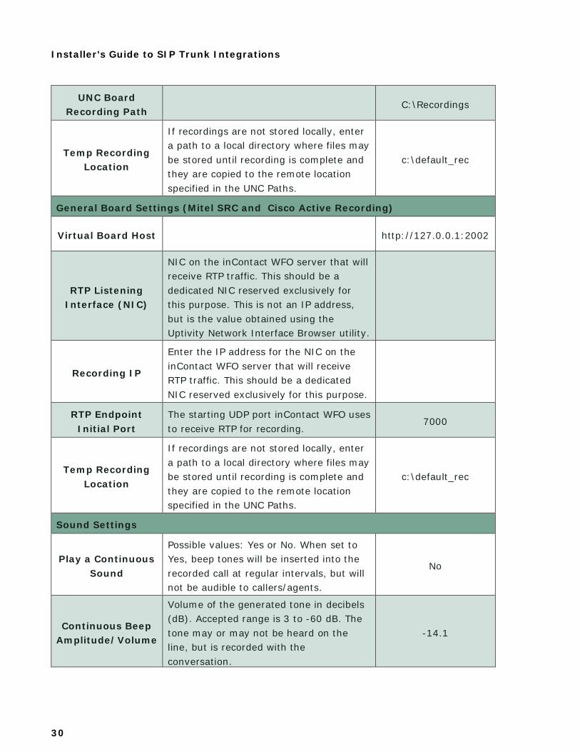
UNC Board Recording Path
C:\Recordings
Temp Recording Location
If recordings are not stored locally, enter a path to a local directory where files may be stored until recording is complete and they are copied to the remote location specified in the UNC Paths.
c:\default_rec
General Board Settings (Mitel SRC and Cisco Active Recording)
Virtual Board Host http://127.0.0.1:2002
RTP Listening Interface (NIC)
NIC on the inContact WFO server that will receive RTP traffic. This should be a dedicated NIC reserved exclusively for this purpose. This is not an IP address, but is the value obtained using the Uptivity Network Interface Browser utility.
Recording IP
Enter the IP address for the NIC on the inContact WFO server that will receive RTP traffic. This should be a dedicated NIC reserved exclusively for this purpose.
RTP Endpoint Initial Port
The starting UDP port inContact WFO uses to receive RTP for recording.
7000
Temp Recording Location
If recordings are not stored locally, enter a path to a local directory where files may be stored until recording is complete and they are copied to the remote location specified in the UNC Paths.
c:\default_rec
Sound Settings
Play a Continuous Sound
Possible values: Yes or No. When set to Yes, beep tones will be inserted into the recorded call at regular intervals, but will not be audible to callers/agents.
No
Continuous Beep Amplitude/Volume
Volume of the generated tone in decibels (dB). Accepted range is 3 to -60 dB. The tone may or may not be heard on the line, but is recorded with the conversation.
-14.1
Installer's Guide to SIP Trunk Integrations
31
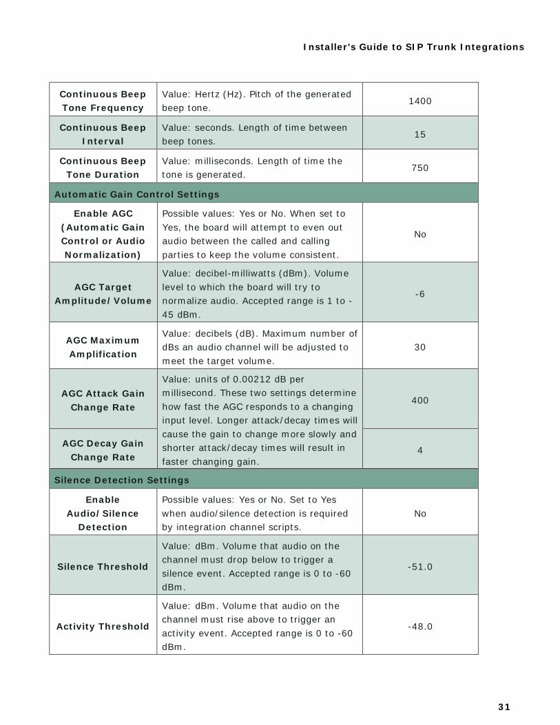
Continuous Beep Tone Frequency
Value: Hertz (Hz). Pitch of the generated beep tone.
1400
Continuous Beep Interval
Value: seconds. Length of time between beep tones.
15
Continuous Beep Tone Duration
Value: milliseconds. Length of time the tone is generated.
750
Automatic Gain Control Settings
Enable AGC (Automatic Gain Control or Audio Normalization)
Possible values: Yes or No. When set to Yes, the board will attempt to even out audio between the called and calling parties to keep the volume consistent.
No
AGC Target Amplitude/Volume
Value: decibel-milliwatts (dBm). Volume level to which the board will try to normalize audio. Accepted range is 1 to -45 dBm.
-6
AGC Maximum Amplification
Value: decibels (dB). Maximum number of dBs an audio channel will be adjusted to meet the target volume.
30
AGC Attack Gain Change Rate
Value: units of 0.00212 dB per millisecond. These two settings determine how fast the AGC responds to a changing input level. Longer attack/decay times will cause the gain to change more slowly and shorter attack/decay times will result in faster changing gain.
400
AGC Decay Gain Change Rate
4
Silence Detection Settings
Enable Audio/Silence
Detection
Possible values: Yes or No. Set to Yes when audio/silence detection is required by integration channel scripts.
No
Silence Threshold
Value: dBm. Volume that audio on the channel must drop below to trigger a silence event. Accepted range is 0 to -60 dBm.
-51.0
Activity Threshold
Value: dBm. Volume that audio on the channel must rise above to trigger an activity event. Accepted range is 0 to -60 dBm.
-48.0

Installer's Guide to SIP Trunk Integrations
32
Minimum Silence Duration
Value: milliseconds. Minimum time the volume level must stay below the silence threshold for an event to be triggered.
40
Maximum Silence Duration
Value: milliseconds. Maximum time in milliseconds that audio can be below the silence threshold before another event is triggered. Max allowed value for this field is 65,535; setting a value higher than this causes the system to reset to 1000.
30000
Minimum Activity Duration
Value: milliseconds. Minimum time the volume level must stay above the activity threshold for an event to be triggered.
40
Maximum Activity Duration
Value: milliseconds. Maximum time that audio can stay above the activity threshold before another event is triggered.
10000
PBX Addresses
Click Add to enter IP Addresses of any non-endpoint device that would be sending RTP to signaling traffic.
UNC Paths
Click Add to enter UNC path values that tell the module where to copy recordings to inContact WFO when recording is complete. You can specify multiple UNC paths in cases where different schedules store files to different locations. In Local, enter the location of the recordings directory on the inContact WFO server. In Remote, enter the UNC path used to reach this directory remotely.
Channel Configuration Setting Definitions
The following table lists and defines the settings that may apply to channels. Individual settings appear in the inContact WFO Web Portal only if they are applicable to the type of Voice Board and channel being configured. Therefore, the table lists all settings in alphabetical order. The table also indicates default settings where applicable; not all settings have a default value.
Setting Definition Default
Number of Channels
Select the number of channels and signal type the Ai-Logix card uses from the drop-down list.
Installer's Guide to SIP Trunk Integrations
33
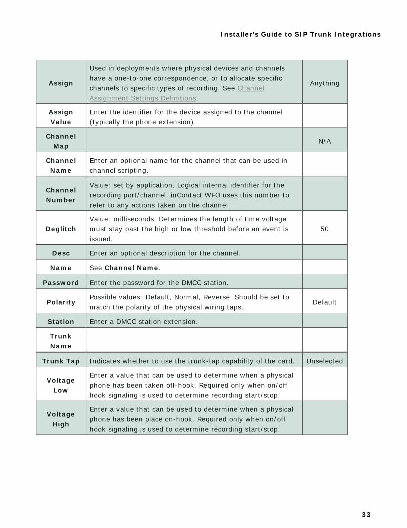
Assign
Used in deployments where physical devices and channels have a one-to-one correspondence, or to allocate specific channels to specific types of recording. See Channel Assignment Settings Definitions.
Anything
Assign Value
Enter the identifier for the device assigned to the channel (typically the phone extension).
Channel Map
N/A
Channel Name
Enter an optional name for the channel that can be used in channel scripting.
Channel Number
Value: set by application. Logical internal identifier for the recording port/channel. inContact WFO uses this number to refer to any actions taken on the channel.
Deglitch Value: milliseconds. Determines the length of time voltage must stay past the high or low threshold before an event is issued.
50
Desc Enter an optional description for the channel.
Name See Channel Name.
Password Enter the password for the DMCC station.
Polarity Possible values: Default, Normal, Reverse. Should be set to match the polarity of the physical wiring taps.
Default
Station Enter a DMCC station extension.
Trunk Name
Trunk Tap Indicates whether to use the trunk-tap capability of the card. Unselected
Voltage Low
Enter a value that can be used to determine when a physical phone has been taken off-hook. Required only when on/off hook signaling is used to determine recording start/stop.
Voltage High
Enter a value that can be used to determine when a physical phone has been place on-hook. Required only when on/off hook signaling is used to determine recording start/stop.
Installer's Guide to SIP Trunk Integrations
34
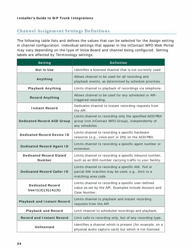
Channel Assignment Settings Definitions
The following table lists and defines the values that can be selected for the Assign setting in channel configuration. Individual settings that appear in the inContact WFO Web Portal may vary depending on the type of Voice Board and channel being configured. Setting labels are affected by Terminology settings.
Setting Definition
Not in Use Identifies a licensed channel that is not currently used.
Anything Allows channel to be used for all recording and playback events, as determined by schedule priorities.
Playback Anything Limits channel to playback of recordings via telephone.
Record Anything Allows channel to be used for any scheduled or API-triggered recording.
Instant Record Dedicates channel to instant recording requests from the API.
Dedicated Record ACD Group Limits channel to recording only the specified ACD/PBX group (not inContact WFO Group), independently of any schedules.
Dedicated Record Device ID Limits channel to recording a specific hardware resource (e.g., voice port or DN) on the ACD/PBX.
Dedicated Record Agent ID Limits channel to recording a specific agent number or extension.
Dedicated Record Dialed Number
Limits channel to recording a specific inbound number, such as an 800-number carrying traffic to your facility.
Dedicated Record Caller ID Limits channel to recording a specific ANI. Full or partial ANI matches may be used, e.g., limit to a matching area code.
Dedicated Record User1(2)(3)(4)(5)
Limits channel to recording a specific user-defined value as set by the API. Examples include Account and Case Number.
Playback and Instant Record Limits channel to playback and instant recording requests from the API.
Playback and Record Limit channel to scheduled recordings and playback.
Record and Instant Record Limit calls to recording only, but of any recording type.
Unlicensed Identifies a channel which is present (for example, on a physical audio capture card) but which is not licensed.
Installer's Guide to SIP Trunk Integrations
35
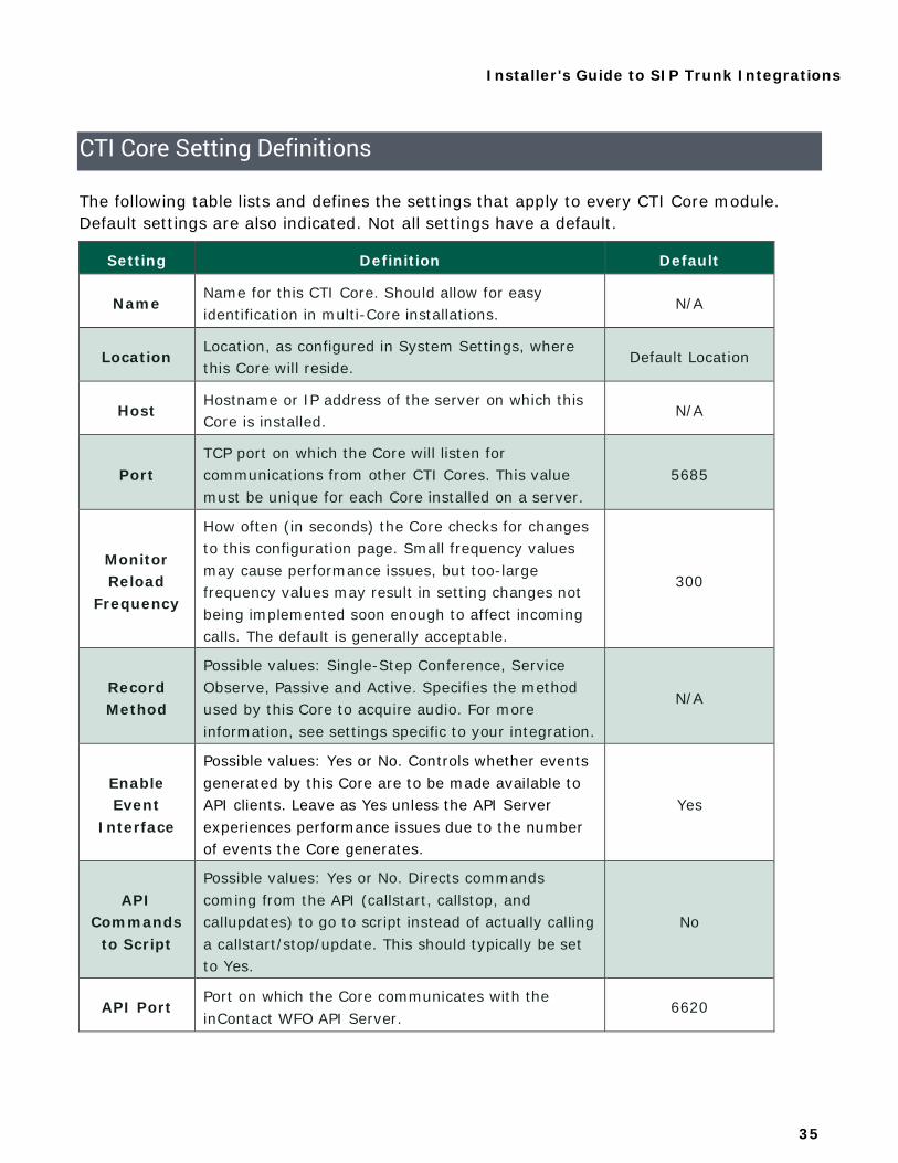
CTI Core Setting Definitions
The following table lists and defines the settings that apply to every CTI Core module. Default settings are also indicated. Not all settings have a default.
Setting Definition Default
Name Name for this CTI Core. Should allow for easy identification in multi-Core installations.
N/A
Location Location, as configured in System Settings, where this Core will reside.
Default Location
Host Hostname or IP address of the server on which this Core is installed.
N/A
Port TCP port on which the Core will listen for communications from other CTI Cores. This value must be unique for each Core installed on a server.
5685
Monitor Reload
Frequency
How often (in seconds) the Core checks for changes to this configuration page. Small frequency values may cause performance issues, but too-large frequency values may result in setting changes not being implemented soon enough to affect incoming calls. The default is generally acceptable.
300
Record Method
Possible values: Single-Step Conference, Service Observe, Passive and Active. Specifies the method used by this Core to acquire audio. For more information, see settings specific to your integration.
N/A
Enable Event
Interface
Possible values: Yes or No. Controls whether events generated by this Core are to be made available to API clients. Leave as Yes unless the API Server experiences performance issues due to the number of events the Core generates.
Yes
API Commands
to Script
Possible values: Yes or No. Directs commands coming from the API (callstart, callstop, and callupdates) to go to script instead of actually calling a callstart/stop/update. This should typically be set to Yes.
No
API Port Port on which the Core communicates with the inContact WFO API Server.
6620
Installer's Guide to SIP Trunk Integrations
36
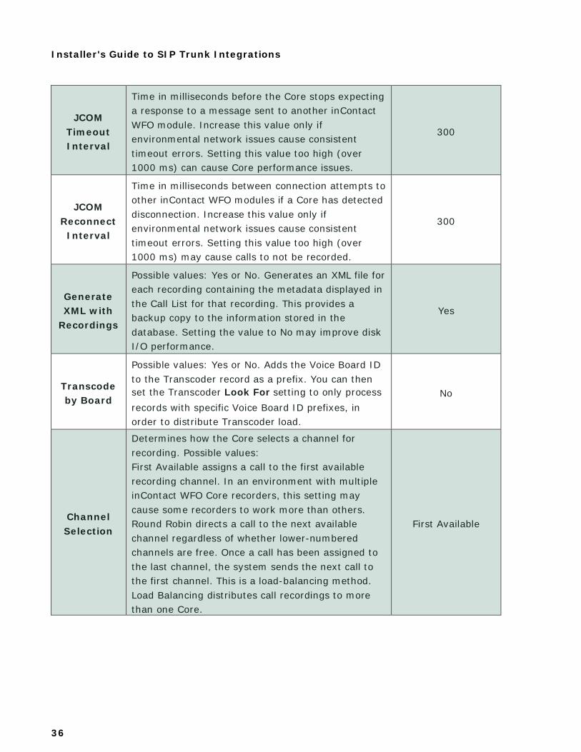
JCOM Timeout Interval
Time in milliseconds before the Core stops expecting a response to a message sent to another inContact WFO module. Increase this value only if environmental network issues cause consistent timeout errors. Setting this value too high (over 1000 ms) can cause Core performance issues.
300
JCOM Reconnect Interval
Time in milliseconds between connection attempts to other inContact WFO modules if a Core has detected disconnection. Increase this value only if environmental network issues cause consistent timeout errors. Setting this value too high (over 1000 ms) may cause calls to not be recorded.
300
Generate XML with
Recordings
Possible values: Yes or No. Generates an XML file for each recording containing the metadata displayed in the Call List for that recording. This provides a backup copy to the information stored in the database. Setting the value to No may improve disk I/O performance.
Yes
Transcode by Board
Possible values: Yes or No. Adds the Voice Board ID to the Transcoder record as a prefix. You can then set the Transcoder Look For setting to only process records with specific Voice Board ID prefixes, in order to distribute Transcoder load.
No
Channel Selection
Determines how the Core selects a channel for recording. Possible values: First Available assigns a call to the first available recording channel. In an environment with multiple inContact WFO Core recorders, this setting may cause some recorders to work more than others. Round Robin directs a call to the next available channel regardless of whether lower-numbered channels are free. Once a call has been assigned to the last channel, the system sends the next call to the first channel. This is a load-balancing method. Load Balancing distributes call recordings to more than one Core.
First Available
Installer's Guide to SIP Trunk Integrations
37
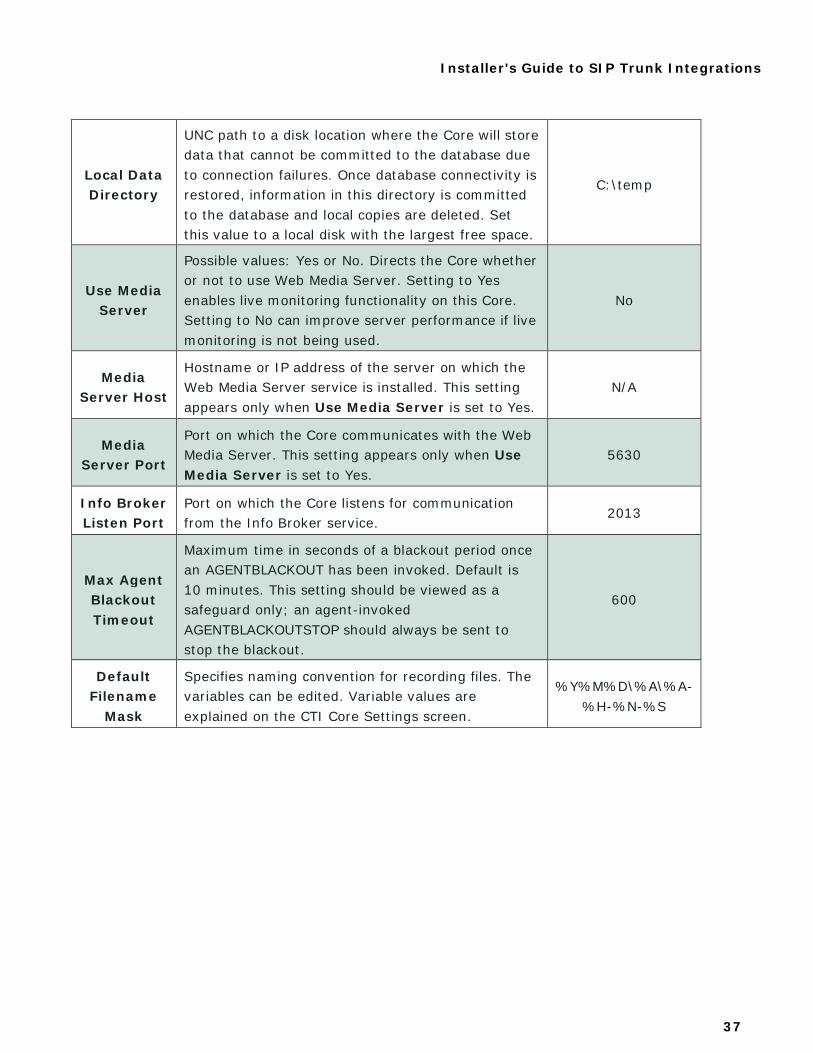
Local Data Directory
UNC path to a disk location where the Core will store data that cannot be committed to the database due to connection failures. Once database connectivity is restored, information in this directory is committed to the database and local copies are deleted. Set this value to a local disk with the largest free space.
C:\temp
Use Media Server
Possible values: Yes or No. Directs the Core whether or not to use Web Media Server. Setting to Yes enables live monitoring functionality on this Core. Setting to No can improve server performance if live monitoring is not being used.
No
Media Server Host
Hostname or IP address of the server on which the Web Media Server service is installed. This setting appears only when Use Media Server is set to Yes.
N/A
Media Server Port
Port on which the Core communicates with the Web Media Server. This setting appears only when Use Media Server is set to Yes.
5630
Info Broker Listen Port
Port on which the Core listens for communication from the Info Broker service.
2013
Max Agent Blackout Timeout
Maximum time in seconds of a blackout period once an AGENTBLACKOUT has been invoked. Default is 10 minutes. This setting should be viewed as a safeguard only; an agent-invoked AGENTBLACKOUTSTOP should always be sent to stop the blackout.
600
Default Filename
Mask
Specifies naming convention for recording files. The variables can be edited. Variable values are explained on the CTI Core Settings screen.
%Y%M%D\%A\%A-%H-%N-%S
Installer's Guide to SIP Trunk Integrations
38
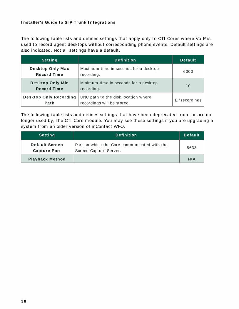
The following table lists and defines settings that apply only to CTI Cores where VoIP is used to record agent desktops without corresponding phone events. Default settings are also indicated. Not all settings have a default.
Setting Definition Default
Desktop Only Max Record Time
Maximum time in seconds for a desktop recording.
6000
Desktop Only Min Record Time
Minimum time in seconds for a desktop recording.
10
Desktop Only Recording Path
UNC path to the disk location where recordings will be stored.
E:\recordings
The following table lists and defines settings that have been deprecated from, or are no longer used by, the CTI Core module. You may see these settings if you are upgrading a system from an older version of inContact WFO.
Setting Definition Default
Default Screen Capture Port
Port on which the Core communicated with the Screen Capture Server.
5633
Playback Method N/A

Installer's Guide to SIP Trunk Integrations
39
Document Revision History Revision Change Description Effective Date
0 Initial version for this release 2016-03-29