institute of space systems - unipi.iteotvos.dm.unipi.it/workshop2010/talks/hdittus0210.pdf · folie...
TRANSCRIPT

Folie 1
The
DLR-Institute of Space Systems (DLR-RY)
and Fundamental Physics
Hansjörg Dittus

Folie 2GG-WS, Pisa, 12.2.2010
Institute of Space Systems Mission
…………
……The
Institute develops
concepts
for
innovative space
missions
on high
national and international standard. Space based
applications
needed
for
scienctific, commercial
and security-relevant
purposes
will be
developed
and carried
out in cooperative
projects
with
other
research
institutions
and industry.……………

Folie 3GG-WS, Pisa, 12.2.2010
Institute of Space Systems (DLR-RY) Structure
System Analysis
Orbital Systems
System Test
and
Verifiaction
Avionic
Systems
Science Missions
System Analysis
Space
Transportation Navigation
and
Control
Systems
Transport andPropulsion
Systems
Orbital Systems
and
Security
Exploration
Systems

Folie 4GG-WS, Pisa, 12.2.2010
AsteoridFinder
/ Start Phase B
System Lead, Institute of Space Systems, DLR-RY
Instrument development
(telescope) and scientific
lead, Institute of Planetary
Research, DLR-PF
6 more
DLR Institutes contributing:
RM, RB, DFD, FA, ME, SC
Scheduled
launch: 2012
Mission statement:TheAsteroidFinder
Mission observes the population of Near Earth Objects (NEOs), in particular IEOs
(Inner Earth Objects / Interior to Earth’s orbit
objects) wrt:•Number of objects•Orbit distribution and orbit parameters (ephemeris)•Scale distribution
spacecraftorbiting
the
Earth
Sun
Earth

Folie 5GG-WS, Pisa, 12.2.2010
AsteoridFinder
SSO (600 –
800 km), LTAN 06:00
Payload segment
Elektronic segment
Service segment(Batteries, Reaction wheels,Antennas)
Sun shield
Radiator(Sensor)
Telescopeapertur

Folie 6GG-WS, Pisa, 12.2.2010
AsteoridFinder
Satellite
Basis: satellite
platform: compact
S/C bus:
150 –
200 kg
To be
launched
as „piggy-back“
(secondary
payload)
in a Low-Earth-Orbit
(LEO)
3 axes
stabilised
attitude
no thrusters
unregulated voltage: 18-24V
power supply 285 W
Kcommunication: S-band (omni-direktional) and X-band
Passive thermal control system

Folie 7GG-WS, Pisa, 12.2.2010
Zodiacal
and stray
light
Zodiacal
Light rel.to
0°
declination
Zodiacal
Light over
elongation
0.550.45
16.8 mag / pixel
18.1 mag / pixel18.5 mag / pixel
15.7 16.8 18.1 18.5
16.4 17.4 18.7 19.1
16.6 17.6 18.9 19.4
SOHO
Vulcanoids?
15.7 mag / pixel
~14.9 mag / pixel
14.9
30°-60°
-40°
-+
40°

Folie 8GG-WS, Pisa, 12.2.2010
Instrument-Anforderungen und Möglichkeiten
Images: 5 s-1 (frames per second) (~200 ms exposure time)
Stacking of up to 300 frames within 60 s by means of guide stars .
Requirement: Vlim
> 18,5 mag:
No sunlight into the telescope
No remittance from earth (albedo) into the telescope
CCD temperature (on focal plane): < -80 °C
No sunlight on radiator
No earth infrared on radiator
BUT: Sufficient sunlight on solar panels for energy supply –
needs optimum pointing to the sun

Folie 9GG-WS, Pisa, 12.2.2010
MASCOT (Marco Polo Surface
Scout) Hayabusa
2
Small MASCOT Lander
for:
Hayabusa
2 (JAXA)
Launch: 2014
Asteorid
target: 1999JU3
Lander
touch-down: 2018
Marco Polo NEO Sample Return Mission (ESA/Cosmic
Vision -
Launch: 2018/2019)
Lander
mass: 20 kg
French contribution: power and communication
subsystems
Lander
able
to adjust
itself:
Guarantee
of measuring
position
& mobility
on the
NEO surface
(‚hopping‘)
Total mass
of experimental equipment: 3 kg
→
3 science
instruments
Experimental Experimental devicesdevices1.
Wide
angel
camera
(topography
& geology
of the
landing
terrains)2.
Mikroscope
+ IR spectrometer
(mineralogy
in μm-range)3.
Analyt. instrument
(chemical
composition) or
Radiotomographer
(innere structur)

Folie 10GG-WS, Pisa, 12.2.2010
System Analysis Space Transportation
Running
projects
Lead
of Study
„Bemannter Europäischer Raumtransport“
BERT (Manned
European Space Transportation)
ELV-system
design
in cooperation
with
EADS Astrium
and MT-
Aerospace
/ nationale studies
WOTAN and VENUS
SpaceLiner (in 2009 EU-Project
FAST20XX)
Mikro-Launcher
design
and in cooperation
with
CNES within
the
Aldébaran
Programme
Systems analyses
of propulsion
engine, e.g. ceramic
engine
EU-Hypersonic
projekts
LAPCAT, ATLLAS ...
Facility:
Support for
the
Concurrent
Engineering Facility
High heat-transfer(> 110 MW) thrust
chamber

Folie 11GG-WS, Pisa, 12.2.2010
German Upper Stage
Research Cooperation
Research Cooperation
Upper StageIn cooperation
with
German launcher
industry
EADS-
Astrium,
MT Aerospace, University of Bremen ZARM and 4 DLR-Institutes
Term of 3 years
Focus: Re-ignitable
cryogenic
upper
stage,
5 Technology-Roadmaps:
Propellant Management Technology
Further
Development
of CFD-Tools
Simulation Feeding
System
Composite
Fibre Technology
Avionics
Technology
Testfacility
in Bremen: CryolabCryogenics
LH2, LOX (50l), LN2 (1000l)
Vacuum
chamber
Sloshing
table
Functional in 2012
Photo: NASA Facility

Folie 12GG-WS, Pisa, 12.2.2010
REX- Free Flyer•
Orbital system
for
re-entry
and re-use•
Platform
for
experikments
under
weightlessness•
Highly
variable experimental time (hours
to weeks)
•
Excellent
µg-quality
(~10-6g)•
Platform
for
the
development
of innovative re-
entry
technology•
Re-enty
control•
Landing
control•
Variable size
and weight•
Open for
different launchers
Re-entry
Systems:

Folie 13GG-WS, Pisa, 12.2.2010
Thermal
StructureSystems
Power
Configuration
Scientists & Customer Table
Cost
Mission AnalysisCommunication
Data Mgmt.
Team Leader
PropulsionAOCS
DLR -
Concurrent Engineering Facility
Concurrent Engineering (CE):
Sketch: ESA
Domain
DataExchange
(verbally)
Pre. S/W-Tool: Integrated Design Model (ESA)
External Tool
Sketch: ESA

Folie 14GG-WS, Pisa, 12.2.2010
Rea
ktio
n W
hee
lsM
agn
etic
Torq
uer
Gyr
os
Mag
net
o-
met
erSt
ar-
sen
sor
GPS
Onboard Computer+ Software
GPS SignalGenerator
RotationTable
Tools for AOCS/GNC Development
In1 Out1
Thruster ActuationSystem
In1 Out1
SpacecraftDynamic
In1Out1
Sensors
Out1
OrbitDisturbances
1
Guidance
In1 Out1
Controller
In1
AnalysisMission Req
In1 Out1
Actuators &Configuration
Simulation S/W
Precise
modelling
Validation with
flight
data
Hardware-in-the-Loop-Testbed
Modular structure
Applicable
for
different missions
Tests facilities
for
AOCS componentsGPS-Simulator
3-Axis Rotation Table
Folie 15GG-WS, Pisa, 12.2.2010
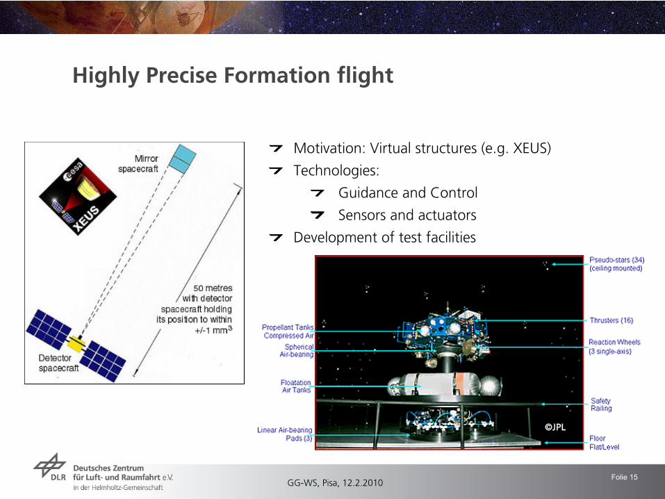
Highly Precise Formation flight
Motivation: Virtual structures (e.g. XEUS)
Technologies:
Guidance and Control
Sensors and actuators
Development of test facilities
©JPL

Folie 16GG-WS, Pisa, 12.2.2010
Autonomous Navigation for Exploration Missions
Motivation:
Precise and soft landing
Autonomous orbit control
Technologis:
Terrain basede
navigation
Hazard avoidance

Folie 17GG-WS, Pisa, 12.2.2010
System Technology Central avionics
Data management
for
space
systems: satellites, launchers
Design: board
computer
and software
Highest
reliability
Innovative concept: Network-Centric
Cooperationen:
STI Spacetec,
Astrium
IHP
Astrofein Technik (TET)
Kayser Threde
(TET)
DLR: OS & SISTEC

Folie 18GG-WS, Pisa, 12.2.2010
Space Technology: Exploration Systems
ProjectsExoMars-Instrument
HP3
Wheel development
for
ExoMars-Rover
StudiesCost-utilization-analysis
of in-situ
missios
vs. sample
return
Moon lander
mission
LAPIS
Geophysical
instrument
package
for
Titan lander
on TSSM
Contribution
to NEXT Lunar
Lander
Phase A (ESA)
Contribution
to Marco Polo Stuy
(‚Cosmic
Vision‘) (ESA)
Marco Polo Lander
‚MASCOT‘
Contribution
to ‚Landing
System‘
Study
(ESA, with
Alenia, Astrium)
Contribution
to HGF-Alliance
„Planetary
Development
and Life“
Running
mission
contributions:Mars Exploration Rover (NASA)
Rosetta (ESA)
HP3
ExoMars-Rad
Marco Polo

Folie 19GG-WS, Pisa, 12.2.2010
FacilitiesCentre for
planetary
landing
Bremen
Simulator LAMA forLanding
dynamics
Rover mobility
Cooperation
with
Astrium
DLR-FA
Planet simulation
chamber
2η11V
Lander
Aufhängung
mk
ΩωΩη
Kraft- und Momentensensorin der Roboterhand
Federelement
LanderKugelgelenk mit schnellerEntkopplung
Space Technology: Exploration Systems

Folie 20GG-WS, Pisa, 12.2.2010
System Test and Verification
Location: Berlin-Adlershof
Facilities
Simulation-
and Test facilities
forSpace environment, vacuum
Sun
Radiation
Mechanischal
loadShaker
shock
centrifuge
Thermal-vacuum
(climate)
EMC-Lab

Folie 21GG-WS, Pisa, 12.2.2010
Sciencet• Theory• Experiments
Universities research
institutes
Sceince
mission
scenarios• Ideas• Innovations•Analysis
RY -
WN
Technique• science
instruments
• classical
payloads
RY, other
DLR institutes, industrial
partners
Space technology• systems
engineering
•concurrent
engineering
RY, SARA
RY –
WN (Science Missions)

Folie 22GG-WS, Pisa, 12.2.2010
Fundamental Physics
Interests
MICROSCOPE (Co-I)
Inertial
sensors
S/C dynamics
–
„science
craft“
S/C precision
AOCS
Precision
thrusters
(laser
ablative
thrusters)
Quantum Optics in space
Quantum sensors
/ space
atom
interferometer
(SAI)
Space clocks
Optical
links / time links
Thermal Modelling
Space Time Anisotropy
Problems in deep
space: communication, energy, propulsion

Folie 23GG-WS, Pisa, 12.2.2010
Challenge: S/C dynamics
Study of appropriate attitude reconstruction method
Kalman
filter, batch filter, …
Development of attitude estimation procedure
Integration into Core Processes
Physical attitude dynamics modelling
Identification of satellite dynamics parameters Smoothing Estimation Results
(Theil et al)
Folie 24GG-WS, Pisa, 12.2.2010
S/C Simulator Objectives
Provide comprehensive simulation of the real system including
science signal and error sources
Provide simulation environment for control system performance validation
Generate data needed to test data reduction methods
Provide capability for identification of the satellite and instrument

Folie 25GG-WS, Pisa, 12.2.2010
Simulator Core Features
Simulation of full satellite and test mass/experiment dynamics in six degrees of freedom by numerical integration of the equations of motion
Multi-body system: e.g. STEP setup: satellite + 8 test masses calculation of 117 states
Consideration of linear and nonlinear coupling forces and torques between satellite and test masses/experiment as well as between test masses/experimental bodies
Modelling of cross-coupling interaction
Earth gravity model up to 360th degree and order,
influence of Sun, Moon and planets can be included
Gravity-gradient forces and torques
5th order Runge-Kutta
numerical integration, Bulirsch-Stoehr, Euler-Cauchy
Several error sources are considered in the model:
+ misalignment and attitude errors
+ coupling biases
+ displacement errors

Folie 26GG-WS, Pisa, 12.2.2010
Force & Torque Modeling
(1/2)
Modeling
of forces and torques acting on the satellite and test masses because of:
Gravitation and Gravity Gradients
Control (forces and torques applied by the control system)
Interaction with the upper layers of the Earth atmosphere
Electromagnetic radiation
heat, radio communication emission
Absorption and reflection of radiation incident (Sun, Albedo, etc.)
Interaction with the magnetic field
Interaction (coupling) between satellite and experiment
From sensor and actuation systems
Gravitational coupling

Folie 27GG-WS, Pisa, 12.2.2010
Force & Torque Modeling
(2/2)
Modeling
approaches:
1. Utilization AND extension of standard models
2. Derivation of parametric models from detailed FEM analysis of
specific
effects
Standard models used:
International Geomagnetic Reference Field (IGRF, IAGA)
Earth Gravity Model (GRACE-based)
Mass Spectrometer Incoherent Scatter Model (MSIS, NRL)
Short-term variations of Earth atmospheric density (analysis of CHAMP mission data)

Folie 28GG-WS, Pisa, 12.2.2010
Verification of Simulator
Comparison to analytical solution of simplified system
Simplified model renders ODE in Mathieu-FormVerification by comparison of stability boundaries
Comparison to Hill‘s Equation
Analytical description of uncoupled relative movement
Comparison to other orbit propagators
Verification of uncoupled attitude motion
Test of dynamic coupling between satellite and test masses
Verification with flight data (Gravity Probe B)

Folie 29GG-WS, Pisa, 12.2.2010
Simulator Architecture
User interface in Matlab/SimulinkSimulator for each mission is assembled from modules.
Modular design makes it easy to include new subsystems
Software
and hardware
in the
loop
capabilities
Application
example:
verification
with
GP-B

Folie 30GG-WS, Pisa, 12.2.2010
MICROSCOPE
X
Z
Y
x-axis: sensitive axisz-axis: satllite
spin
axis
Micro-satellite à Trainée Componsée pour l´Observation du Principe
d´Equivalence
Mission Parameter:
Sun synchronous Orbit: 660 km
Orbit-Excentricity : < 5 · 10-3
Spin-Rate: variabel for modulation, der Orbit-Frequenz
Signal frequency: (π
+1/2) forb und (π
+3/2) forb
Missions duration: 6 to 12 months
Satellite mass: < 120 kg
CNES-Project (with contributions from DLR and ESA)

Folie 31GG-WS, Pisa, 12.2.2010
Redundant measurements
Measuring
acceleration
of S/C on geodesic
via ranging and Doppler tracking
Measuring
redshift
of clocks
on-board
S/C
for
example
Pioneer Anomaly
Clock
exploration
does
not
depend
on geodesic
motion, independent from
non-gravitational
acceleration
Cock
exploration
is
cumulative
Clocks
automatically
isolate
the
pure gravity
sector
Clocks
represent
an absolute DC-accelerometer
Problem: Clocks
to explore
space-time
1390
202 10d1 xac
AU
AUPA
requirement
for
deep space
missions
Allan variance
Challenge:long term stability

Folie 32GG-WS, Pisa, 12.2.2010
Problem: Time transfer
(MWL)
MWL (Microwave
link to ISS) developed
from
PRARE for
time transfer
between
ISS and ground
Frequency
comparison
on the
10-16
level
(230 fs
per pass, 5 ps
per orbit)
2 symmetric
1-way links carrying
continous
pseudo-noise
coded
signals
High Ku-band
chip
rate (100 MChip/s) in order to increase
resolution
and suppress
potential multipath
1 W power (S and Ku-band)
Although
not
planned: ranging would
be
possible
with
λ/1,000 = 24 µm accuracy.

Folie 33GG-WS, Pisa, 12.2.2010
Direct
application
e.g. lunar
gravity
field
exploration
a path
to relativisitc
geodesy
F. Flechtner, GFZ

Folie 34GG-WS, Pisa, 12.2.2010
Future: Optical
linksOptical
transponders
(on-board
lasers, telescopes, timing
receiver)
Demonstrated
over
0.17 AU (24 million
km) with
Messenger S/C and Mars Global Surveyor
S/C (1-way)
Nd:YAG
laser, pulse rate 8 Hz
Needs
atmospheric
correction: calibration
can
be
done
by
ranging to near
earth
objects
(e.g. LAGEOS) from
differnt
stations
Echo transponder
for
e.g. lunar
laser
rangingTime delay
must
be
known
Asynchronous
transponder
for
satellite
laser
rangingRepetition rate must
be
known
Messenger S/C MOLA on Mars Global Surveyor
S/C (1-way only)
range 2.4·107
km 8·107
km
pulsewidth 10 ns (up), 6 ns (down) 5 ns
pulse energy 16 mJ (up), 20 mJ (down) 150 mJ
repetition
rate 240 Hz (up), 8 Hz (down) 56 Hz
laser
power 3.84 W (up), 0.16 W (down) 8.4 W
beam
divergence 60 μrad (up), 100 μrad (down) 50 μrad
receive
area 0.042 m2(up), 1.003 m2
(down) 0.196 m2John J. Degnan, in Lasers, Clocks, and Drag Free…

Folie 35GG-WS, Pisa, 12.2.2010
QUANTUS Collaboration
QUANTUS

Folie 36GG-WS, Pisa, 12.2.2010
Quantum sensorsBased
on:
(1)
Ultra-precise
optical
metrology
δν/ν
< 10-17
in the
optical
frequency
domain
(2)
Phase-sensitive atom
interferometry
δE/E
< 10-19
due
to the
sub-microscopic
quantum
mechanical
structure
Needs
experimental competence
in:
(1)
Processing
ultra-cold
atomic
ensembles:
-
„classical“
laser
cooled
ensembles: ~ 1 μK
-
Bose-Einstein
Condensates
(BEC): < 50 nK
-
ultra-cold
molecules
(2)
Measuring
the
phase
highly
precise:
-
highly
stable, phase-locked
EM-oscialltors
(RF-, THz-, optical)
(3)
Calibrating
oscillators:
-
frequency
comb
Detector Read-out
Quantum Sensor
Compa- rator

Folie 37GG-WS, Pisa, 12.2.2010
Long evolution
time in μg
BEC-TOF: 700 ms (meanwhile 850 ms)
Thermal background disappeared
Ca. 9,000 atoms
Large extension: ca. 0.5 mm

Folie 38GG-WS, Pisa, 12.2.2010
Outlook (Experiments)
Test of the Equivalence Principle with quantum objects
- Freely falling quantum probes / distinct atomic species
- CAPRICE experiment within QUEST- Programme (Quantum Engineering and Space-Time Research)
- M. Kasevich et al. (2007): - Atom interferometer height: ca. 10 m- Wavepackage separation: > 10 cm - statistical accuracy: δg/g < 10-15
- systematic uncertainty: δg/g < 10-16

Folie 39GG-WS, Pisa, 12.2.2010
Summary: DLR-RY competences
System apporach: AsteoridFinder: DLR compact
satellit
„Sciencecraft“Cooperation
with
other
DLR space
related
institutes
for
planetary
research, GSOC/operations, robotics
/mechatronics, communication
/ navigation, technical
physics, light structure
mechanics, construction, and S/W developmentSystem competence
at RY:Lander
(ES)AOCS / precision
attitude
control
(NR)S/C dynamic
simulationavionicssatellite
construction
(OR)System analysis
(SA)Mission analysis
/ concurrent
engineering
(OR / SA)Thermal analysis
(SK / OR)Test and verification
(SK)