instruction manual s1222, rev c air operated 5:1 oil ratio
TRANSCRIPT
1
INSTRUCTION MANUAL S1222, Rev C
Air Operated 5:1 Oil Ratio PumpOP-51Congratulations on purchase of this World Class Air Operated Oil Ratio Pump !
• World-class Industrial Oil Dispensing pumps with guaranteed performance & hassle free operation
• Pumps are designed to work in tough conditions & are ideal for use with high viscosity oils (up to SAE 240) for transferring over short & long distances (up to 50 metres), mostly used with Trolley mounted kits both with & without Hose Reels, as well as with fixed systems for centralized distribution
• All metal construction, fully CNC machined with hardened wear resistant moving parts
• Reciprocating piston operated 2-1/2” (63 mm) dia. Air Motor
• Stub Pumps are supplied with Non Return Valve threaded 1” (F) for use on the bottom of the Suction Tube. Other pump lengths have a built in Strainer at pump inlet to keep contaminants away
• Pumps are double acting with discharge up to 18 LPM (4.76 GPM). Air Consumption: 250 LPM (66 GPM)
• Available in three different sizes - Stub, 16 Gal & 55 Gal version
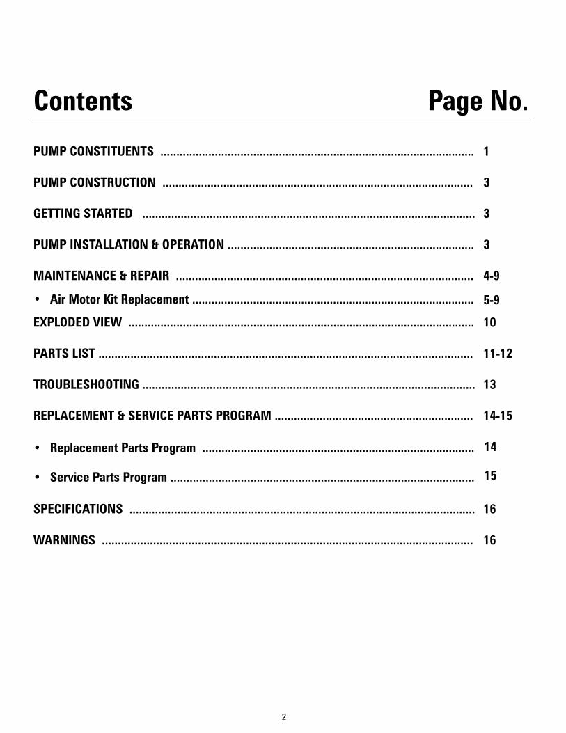
PUMP CONSTITUENTS
1 2
1. Pump Assembly 2. Bung Nut
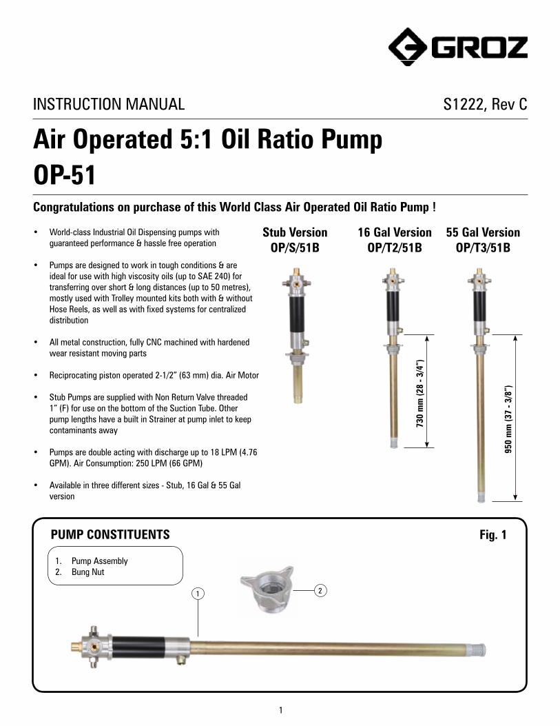
Stub VersionOP/S/51B
16 Gal VersionOP/T2/51B
55 Gal VersionOP/T3/51B
730
mm
(28
- 3/4
”)
950
mm
(37
- 3/8
”)
Fig. 1
2
1
3
3
3
4-9
10
11-12
13
14-15
16
16
Contents Page No.
PUMP CONSTITUENTS ..................................................................................................
PUMP CONSTRUCTION .................................................................................................
GETTING STARTED ........................................................................................................
PUMP INSTALLATION & OPERATION .............................................................................
MAINTENANCE & REPAIR .............................................................................................
EXPLODED VIEW ............................................................................................................
PARTS LIST .....................................................................................................................
TROUBLESHOOTING ........................................................................................................
REPLACEMENT & SERVICE PARTS PROGRAM ..............................................................
SPECIFICATIONS ............................................................................................................
WARNINGS ....................................................................................................................
• Air Motor Kit Replacement ........................................................................................
• Replacement Parts Program .....................................................................................
• Service Parts Program ...............................................................................................
14
15
5-9
3
PUMP CONSTRUCTION
DRIVE SECTION
PUMPING SECTION
The pump is made up of two sections as below :-
• DRIVE SECTION:- It consists of an Air Motor
Assembly driven by compressed air. The piston
diameter of the air motor is 2.5” / 63 mm. The motor
consists of an air cylinder with piston and one
reciprocal valve with a nylon slider. The valve directs
the compressed air alternately to the top or bottom of
the piston, thus producing a reciprocating motion of
the piston rod.
• PUMPING SECTION:- It consists of a pump in
which a piston lifts media through Non Return Valves
by reciprocating inside the suction tube. Media is
discharged with pressure (from the outlet located at
bottom of Air Motor) into the delivery hose / pipe.
NOTE• AIR MOTOR of this pump starts automatically
when the dispensing gun / tap is opened. When the
dispensing gun / tap is closed, air motor builds up
a back-pressure and stops operating the pumping
section.
• PRESSURE RATIO of the pump states the ratio of the
output fluid pressure to the incoming air pressure.
Since the pressure ratio is 5:1, we achieve an output
media pressure up to 750 PSI (50 BAR) when the
incoming air pressure is 150 PSI (10 BAR).
• AIR SUPPLY: An FRL (Filter-Regulator-Lubricator) unit must
be used in the Air supply, before it is connected to the
pump.
Set the regulator to 6 BAR (90 PSI) or any required inlet
pressure, but never more than 150 PSI (10 BAR) or less
than 30 PSI (2 BAR).
When not in use & at the end of each day , air supply to the
pump must be switched off.
• DISCHARGE HOSE: It is recommended to use a hose with
½” I.D., with a Working Pressure of not less than 400 PSI
(28 BAR). Burst Pressure must be atleast 1000 PSI (70
BAR) or more. Using a smaller I.D. hose will cause higher
pressure loss.
• DISPENSING GUN: Based on the application, you may use
a gun that is compatible with media being dispensed.
• THREAD SEALANT: Apply thread sealant on all threaded
connections to ensure leak-proof operation.
GETTING STARTEDBefore installing the pump, make sure the following are available: 1. Slide out the Bung from Suction Tube & screw it into the 2”
opening on the drum.
2. Loosen the ring nut on Bung & carefully insert the pump
Suction Tube through it. Once the Suction Tube touches the
bottom of drum, tighten the ring nut.
3. Connect the appropriate hose and dispensing gun to the
pump outlet. Use a thread sealant to avoid any leakage.
4. With the air supply turned off, connect the air line into the air
inlet on the pump. Remove the vent plug on drum to create
the required venting for pump operation.
5. Partially open the on/off air valve (It helps in creating initial
vacuum when filling a totally dry pump). Pump will start
operating automatically until it gets primed. Pump is said
to be Primed when media is available at the pump outlet,
making the pump ready to use. Once primed, the air motor
will stop. Open the on/off air valve fully.
6. Operate the dispensing gun, which will actuate the air motor
& pump will start dispensing.
PUMP INSTALLATION & OPERATION
Fig. 2
4
MAINTENANCE & REPAIR (Refer to Exploded View - Page 10)
General Precautions• Before performing any service operation, always shut off the air supply and release the system pressure i.e. let the media out so
that the pressure decreases. When storing the pump assembly out of the drum, cover the Filter Tube (62) with Filter Cap (63).
• Be careful not to damage any parts when dismantling. While removing shafts which do not have key flats, use a Pipe wrench,
Strap wrench or the like. The easiest way to remove such a shaft is to grip it in a vice with aluminium or copper jaws, clamp the
shaft in a hand-drill chuck and then turn the chuck by hand.
• Be careful when fitting O-rings and seals. Always lubricate them with oil before fitting. They must never be threaded over sharp
edges when being fitted. Lubricate all moving parts with oil.
• When troubleshooting, be on a lookout for dirt in valves / ball seats, scratches in sealing surfaces & damage in O-rings / seals /
gaskets.
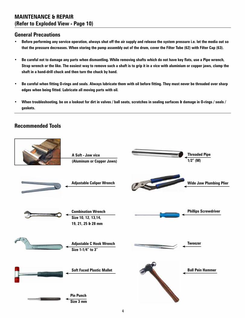
Recommended Tools
Combination Wrench
Size 10, 12, 13,14,
19, 21, 25 & 28 mm
Adjustable C Hook Wrench
Size 1-1/4” to 3”
Soft Faced Plastic Mallet Ball Pein Hammer
Wide Jaw Plumbing PlierAdjustable Caliper Wrench
A Soft - Jaw vice
(Aluminum or Copper Jaws)
Pin Punch
Size 3 mm
Tweezer
Threaded Pipe
1/2” (M)
Phillips Screwdriver
5
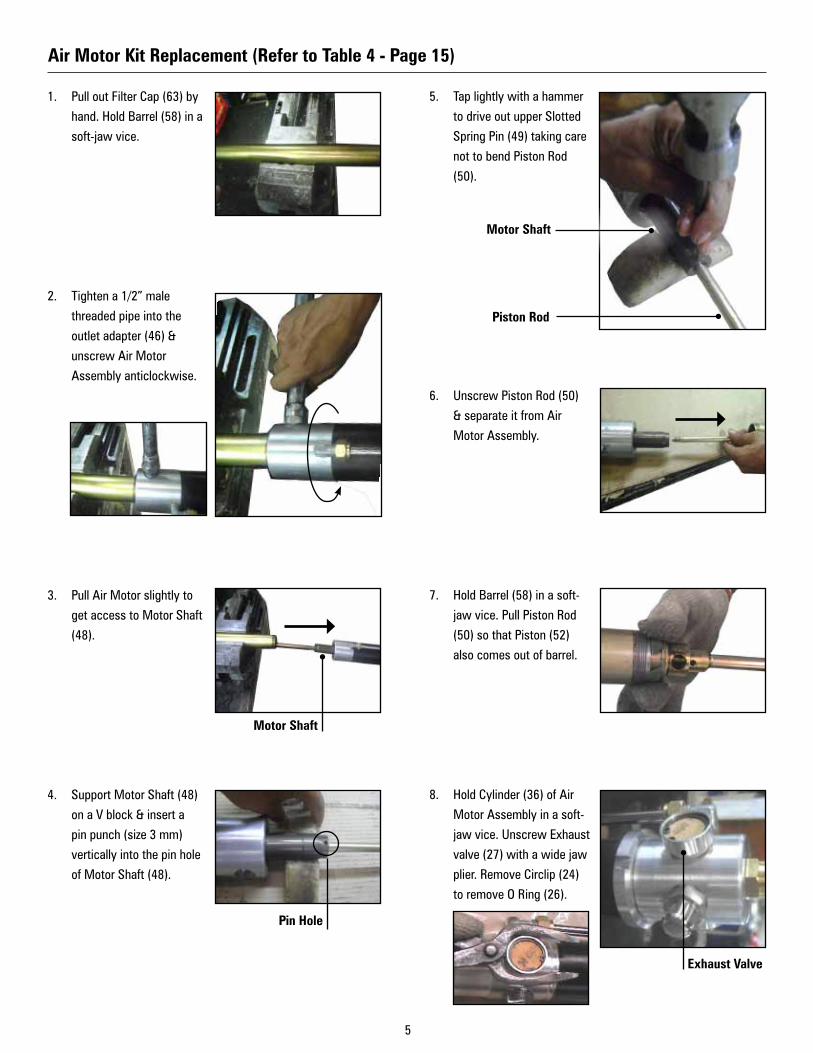
5. Tap lightly with a hammer
to drive out upper Slotted
Spring Pin (49) taking care
not to bend Piston Rod
(50).
6. Unscrew Piston Rod (50)
& separate it from Air
Motor Assembly.
7. Hold Barrel (58) in a soft-
jaw vice. Pull Piston Rod
(50) so that Piston (52)
also comes out of barrel.
8. Hold Cylinder (36) of Air
Motor Assembly in a soft-
jaw vice. Unscrew Exhaust
valve (27) with a wide jaw
plier. Remove Circlip (24)
to remove O Ring (26).
1. Pull out Filter Cap (63) by
hand. Hold Barrel (58) in a
soft-jaw vice.
2. Tighten a 1/2” male
threaded pipe into the
outlet adapter (46) &
unscrew Air Motor
Assembly anticlockwise.
3. Pull Air Motor slightly to
get access to Motor Shaft
(48).
4. Support Motor Shaft (48)
on a V block & insert a
pin punch (size 3 mm)
vertically into the pin hole
of Motor Shaft (48).
Air Motor Kit Replacement (Refer to Table 4 - Page 15)
Motor Shaft
Pin Hole
Piston Rod
Motor Shaft
Exhaust Valve
6
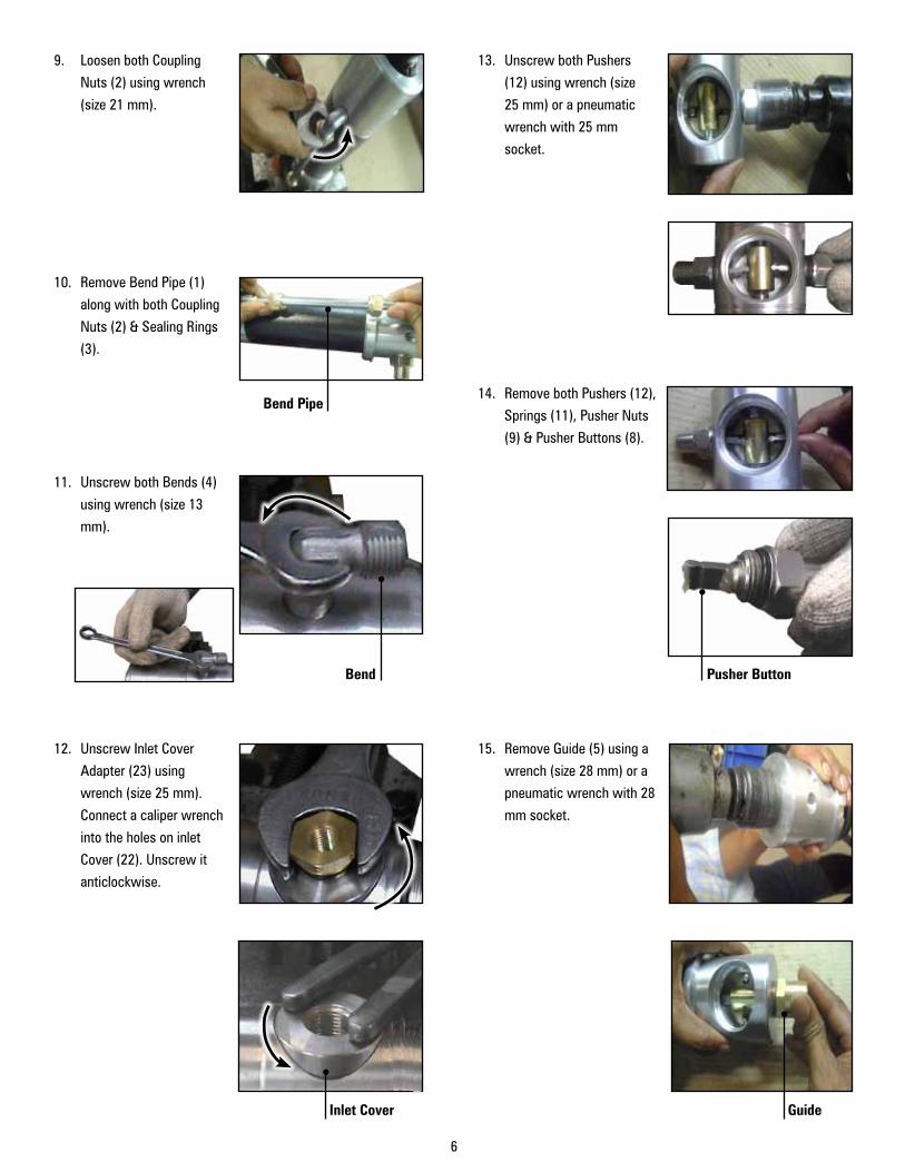
9. Loosen both Coupling
Nuts (2) using wrench
(size 21 mm).
10. Remove Bend Pipe (1)
along with both Coupling
Nuts (2) & Sealing Rings
(3).
11. Unscrew both Bends (4)
using wrench (size 13
mm).
12. Unscrew Inlet Cover
Adapter (23) using
wrench (size 25 mm).
Connect a caliper wrench
into the holes on inlet
Cover (22). Unscrew it
anticlockwise.
13. Unscrew both Pushers
(12) using wrench (size
25 mm) or a pneumatic
wrench with 25 mm
socket.
14. Remove both Pushers (12),
Springs (11), Pusher Nuts
(9) & Pusher Buttons (8).
15. Remove Guide (5) using a
wrench (size 28 mm) or a
pneumatic wrench with 28
mm socket.
Bend Pusher Button
Bend Pipe
Inlet Cover Guide

7
19. Pull out Rubber Plunger
(38).
20. Hold Stopper (39) with
a wrench (size 10 mm)
& unscrew Slider (19)
anticlockwise with a
wrench (size 12 mm).
Disconnect Plunger Rod
(29). Remove Slider (19)
from top of the Housing
(7).
21. Unscrew Housing Rod
Guide (33) anticlockwise
with a wrench (size 28
mm) or a pneumatic
wrench with 28 mm
socket.
16. Tap around Clamping
Ring (34) with a plastic
hammer. Loosen Clamping
Ring (34) using an
Adjustable C Hook
Wrench (Size 1-1/4” to
3”). Turn it anticlockwise.
17. Tap around Housing (7)
of Air Motor with plastic
hammer. Hold Housing
(7) in the Soft-jaw vice.
Tighten a 1/2” male
threaded pipe into the
outlet adapter (46) &
unscrew anticlockwise to
disconnect Housing (7)
from Cylinder (36) & Shaft
Body (41).
18. Hold Plunger Rod Guide
(37) with a wrench (size
19 mm). Unscrew Motor
Shaft (48) by turning it
anticlockwise with a pin
punch (size 3 mm).
Motor Shaft
Pin Hole
Turn the Slider
Hold the Stopper
Rod Guide
8
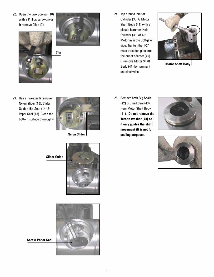
24. Tap around joint of
Cylinder (36) & Motor
Shaft Body (41) with a
plastic hammer. Hold
Cylinder (36) of Air
Motor in in the Soft-jaw
vice. Tighten the 1/2”
male threaded pipe into
the outlet adapter (46)
& remove Motor Shaft
Body (41) by turning it
anticlockwise.
25. Remove both Big Seals
(42) & Small Seal (43)
from Motor Shaft Body
(41). Do not remove the
Turcite washer (44) as
it only guides the shaft
movement (It is not for
sealing purpose).
22. Open the two Screws (18)
with a Philips screwdriver
& remove Clip (17).
23. Use a Tweezer & remove
Nylon Slider (16), Slider
Guide (15), Seat (14) &
Paper Seal (13). Clean the
bottom surface thoroughly.
Nylon Slider
Motor Shaft Body
Seat & Paper Seal
Slider Guide
Clip
9
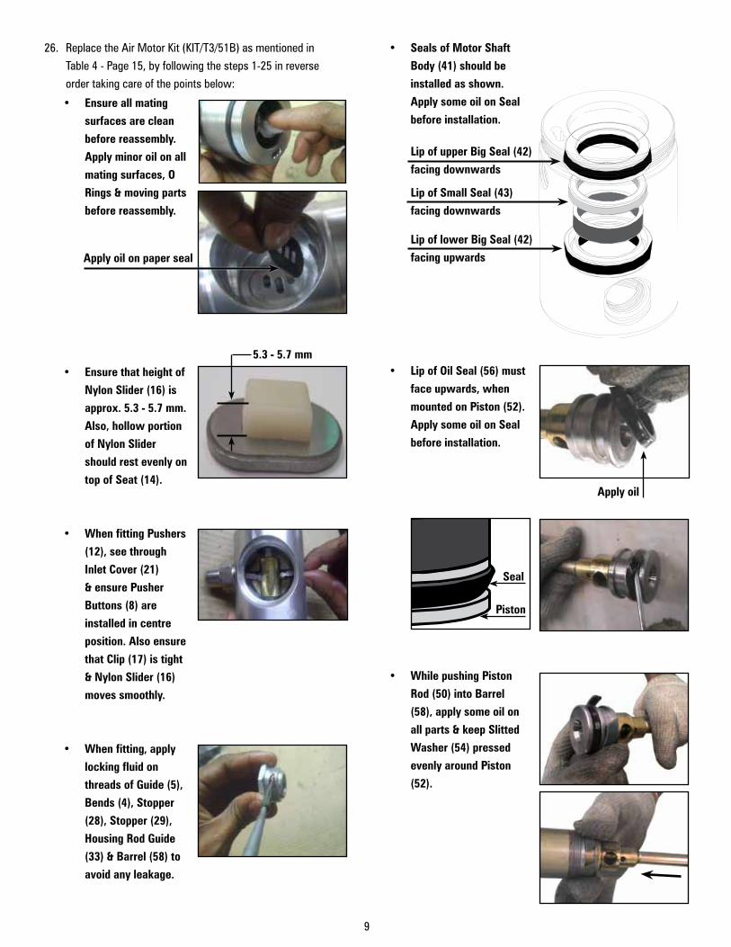
• Seals of Motor Shaft
Body (41) should be
installed as shown.
Apply some oil on Seal
before installation.
• Lip of Oil Seal (56) must
face upwards, when
mounted on Piston (52).
Apply some oil on Seal
before installation.
• While pushing Piston
Rod (50) into Barrel
(58), apply some oil on
all parts & keep Slitted
Washer (54) pressed
evenly around Piston
(52).
• Ensure all mating
surfaces are clean
before reassembly.
Apply minor oil on all
mating surfaces, O
Rings & moving parts
before reassembly.
• Ensure that height of
Nylon Slider (16) is
approx. 5.3 - 5.7 mm.
Also, hollow portion
of Nylon Slider
should rest evenly on
top of Seat (14).
• When fitting Pushers
(12), see through
Inlet Cover (21)
& ensure Pusher
Buttons (8) are
installed in centre
position. Also ensure
that Clip (17) is tight
& Nylon Slider (16)
moves smoothly.
• When fitting, apply
locking fluid on
threads of Guide (5),
Bends (4), Stopper
(28), Stopper (29),
Housing Rod Guide
(33) & Barrel (58) to
avoid any leakage.
5.3 - 5.7 mm
Apply oil on paper seal
Seal
Piston
26. Replace the Air Motor Kit (KIT/T3/51B) as mentioned in
Table 4 - Page 15, by following the steps 1-25 in reverse
order taking care of the points below:
Apply oil
Lip of upper Big Seal (42)
facing downwards
Lip of Small Seal (43)
facing downwards
Lip of lower Big Seal (42)
facing upwards
10
5
13
14
1718
1920
21
1
2
2
3
3
4
4
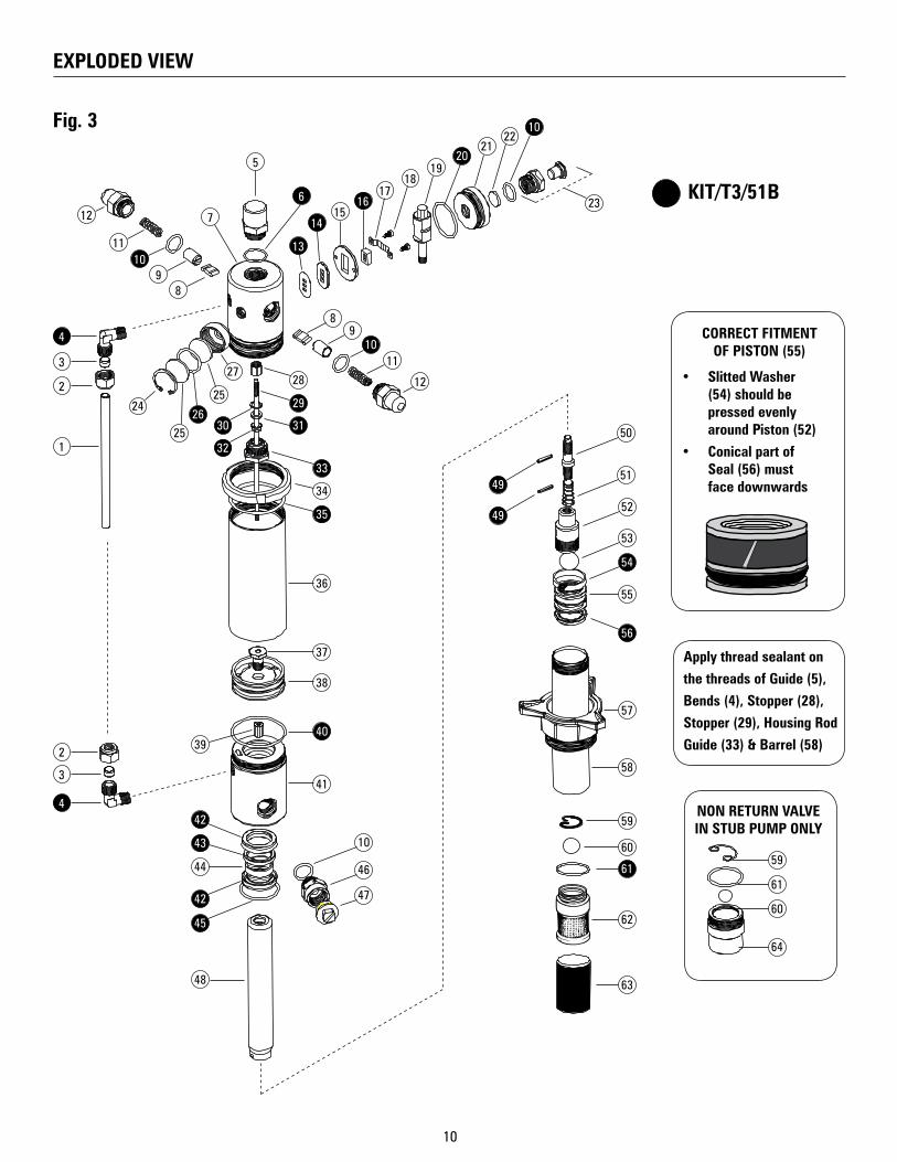
EXPLODED VIEW
Fig. 3
6
7
8
89
910
1011
12
12
11
1516
2210
23
24
2526
25
2728
29
3130
32
34
33
35
4039
42
48
42
49
49
45
10
50
51
53
54
55
57
58
59
60
61
64
60
61
59
62
63
56
52
46
47
43
44
36
37
38
41
Apply thread sealant on
the threads of Guide (5),
Bends (4), Stopper (28),
Stopper (29), Housing Rod
Guide (33) & Barrel (58)
NON RETURN VALVE IN STUB PUMP ONLY
CORRECT FITMENT OF PISTON (55)
• Slitted Washer (54) should be pressed evenly around Piston (52)
• Conical part of Seal (56) must face downwards
KIT/T3/51B
11
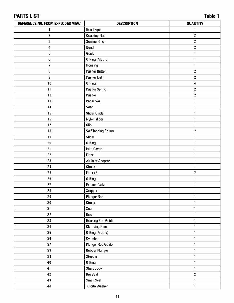
REFERENCE NO. FROM EXPLODED VIEW DESCRIPTION QUANTITY
1 Bend Pipe 1
2 Coupling Nut 2
3 Sealing Ring 2
4 Bend 2
5 Guide 1
6 O Ring (Metric) 1
7 Housing 1
8 Pusher Button 2
9 Pusher Nut 2
10 O Ring 4
11 Pusher Spring 2
12 Pusher 2
13 Paper Seal 1
14 Seat 1
15 Slider Guide 1
16 Nylon slider 1
17 Clip 1
18 Self Tapping Screw 2
19 Slider 1
20 O Ring 1
21 Inlet Cover 1
22 Filter 1
23 Air Inlet Adapter 1
24 Circlip 1
25 Filter (B) 2
26 O Ring 1
27 Exhaust Valve 1
28 Stopper 1
29 Plunger Rod 1
30 Circlip 1
31 Seal 1
32 Bush 1
33 Housing Rod Guide 1
34 Clamping Ring 1
35 O Ring (Metric) 1
36 Cylinder 1
37 Plunger Rod Guide 1
38 Rubber Plunger 1
39 Stopper 1
40 O Ring 1
41 Shaft Body 1
42 Big Seal 2
43 Small Seal 1
44 Turcite Washer 1
PARTS LIST Table 1
12
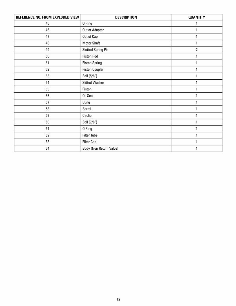
REFERENCE NO. FROM EXPLODED VIEW DESCRIPTION QUANTITY
45 O Ring 1
46 Outlet Adapter 1
47 Outlet Cap 1
48 Motor Shaft 1
49 Slotted Spring Pin 2
50 Piston Rod 1
51 Piston Spring 1
52 Piston Coupler 1
53 Ball (5/8”) 1
54 Slitted Washer 1
55 Piston 1
56 Oil Seal 1
57 Bung 1
58 Barrel 1
59 Circlip 1
60 Ball (7/8”) 1
61 O Ring 1
62 Filter Tube 1
63 Filter Cap 1
64 Body (Non Return Valve) 1

13
PROBLEM POSSIBLE CAUSE SOLUTION
Pump operates, but does not dispense media at all
Media viscosity is too highMake sure that media used has a viscosity of SAE 240 or lower
Drum is Empty Media level inside the drum may be too low. Refill drum
Pump inlet is blocked Remove suction tube & clean strainer at pump inlet
Air Inlet Pressure is too less Increase air pressure. It must be at least 30 PSI (2 BAR)
Pump not working / less discharge
Air Inlet pressure is too less Increase air pressure. It must be at least 30 PSI (2 BAR)
Nylon Slider (16) is jammed / overtight
1. Check for any build-up edge on Clip (17) & tighten it again. Make sure the movement of Nylon Slider (16) is neither very loose nor very tight
2. If needed, replace Nylon Slider (16). Also replace the Paper Seal (13) & Seat (14) to ensure the best fitting
Plunger (38) / Plunger Rod (39) / Piston Rod (50) / Piston (52) jammed.
1. Remove suction tube. Disconnect Air Motor Assembly from Pumping Section by removing the upper Slotted Spring Pin (49) from Motor Shaft (48)
2. Supply input air to Air Motor. If it works properly without the barrel assembly, then the problem lies with the pumping section. Otherwise check the Air Motor for smooth movement
3. After locating the faulty section, check the respective Piston / Plunger & the associated washers & seals for any overlap or wear & tear. Replace the defective parts from Repair Kit
4. Ensure to replace the moving parts having close tolerances (such as Nylon Slider (27), Paper Seal (13) & Seat (14) as a SET to ensure the best fitting
Pump continues to operate even after the trigger of dispensing gun has been released
Air Leakage in the pump assembly
Check all the connections to ensure they are air tight. Use thread sealant.Check O rings & seals for damage. Replace the defective parts from Repair Kit
Media comes through the air Exhaust Valve (27)
Media leaks into the Air Motor Check O Ring (45), Seals (42), (43), Oil Seal (56) & Slitted Washer (54) for wear & tear. Replace the damaged parts from Repair Kit
Air passes directly from inlet to the outlet & pump does not work
Nylon Slider (16) is jammed / overtight
1. Check for any build-up edge on Clip (17) & tighten it again. Make sure the movement of Nylon Slider (16) is neither very loose nor very tight
2. If needed, replace Nylon Slider (16). Also replace the Paper Seal (13) & Seat (14) to ensure the best fitting
Discharge suddenly stopped while the pump was running
Seals / O Rings DamageCheck all seals / O Rings & replace the damaged parts from Repair Kit
Chip / Other foreign particles get clogged at dispensing gun / discharge outlet
Clean all foreign particles / chips
Clogging of Filter Tube (62) / Non Return Valve Body (64)
Open, clean it & reassemble it properly
TROUBLESHOOTING (Refer to Exploded View - Page 10)
Table 2
14
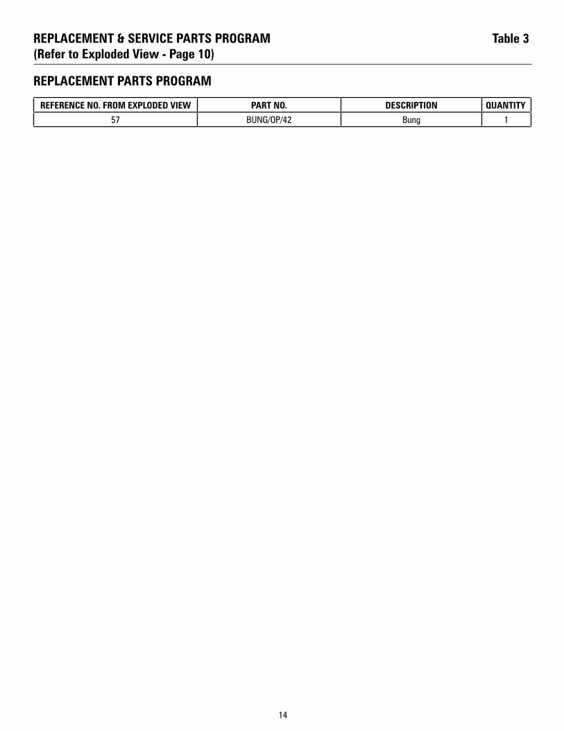
REPLACEMENT PARTS PROGRAM
REFERENCE NO. FROM EXPLODED VIEW PART NO. DESCRIPTION QUANTITY
57 BUNG/OP/42 Bung 1
REPLACEMENT & SERVICE PARTS PROGRAM (Refer to Exploded View - Page 10)
Table 3
15
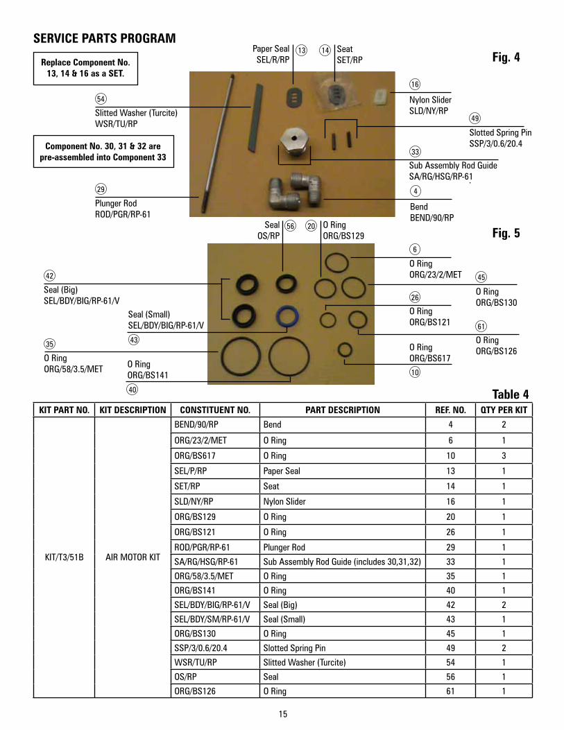
SERVICE PARTS PROGRAM
KIT PART NO. KIT DESCRIPTION CONSTITUENT NO. PART DESCRIPTION REF. NO. QTY PER KIT
KIT/T3/51B AIR MOTOR KIT
BEND/90/RP Bend 4 2
ORG/23/2/MET O Ring 6 1
ORG/BS617 O Ring 10 3
SEL/P/RP Paper Seal 13 1
SET/RP Seat 14 1
SLD/NY/RP Nylon Slider 16 1
ORG/BS129 O Ring 20 1
ORG/BS121 O Ring 26 1
ROD/PGR/RP-61 Plunger Rod 29 1
SA/RG/HSG/RP-61 Sub Assembly Rod Guide (includes 30,31,32) 33 1
ORG/58/3.5/MET O Ring 35 1
ORG/BS141 O Ring 40 1
SEL/BDY/BIG/RP-61/V Seal (Big) 42 2
SEL/BDY/SM/RP-61/V Seal (Small) 43 1
ORG/BS130 O Ring 45 1
SSP/3/0.6/20.4 Slotted Spring Pin 49 2
WSR/TU/RP Slitted Washer (Turcite) 54 1
OS/RP Seal 56 1
ORG/BS126 O Ring 61 1
Table 4
Fig. 4
Fig. 5
Slitted Washer (Turcite)WSR/TU/RP
Sub Assembly Rod Guide SA/RG/HSG/RP-61
Plunger RodROD/PGR/RP-61
Seal (Big)SEL/BDY/BIG/RP-61/V
O RingORG/58/3.5/MET
54
29
42
35
BendBEND/90/RP
Nylon SliderSLD/NY/RP
O RingORG/23/2/MET
O RingORG/BS121
O RingORG/BS617
O RingORG/BS130
O RingORG/BS126
SeatSET/RP
O RingORG/BS129
SealOS/RP
Slotted Spring PinSSP/3/0.6/20.4
4
16
6
26
10
45
61
49
33
Replace Component No. 13, 14 & 16 as a SET.
Component No. 30, 31 & 32 are pre-assembled into Component 33
Paper SealSEL/R/RP
13 14
2056
Seal (Small)SEL/BDY/BIG/RP-61/V
O RingORG/BS141
43
40
16
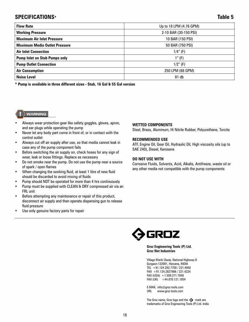
Groz Engineering Tools (P) Ltd.Groz Net Industries
Village Kherki Daula, National Highway-8Gurgaon-122001, Haryana, INDIATEL +91.124.282.7700 / 221.4050FAX +91.124.2827986 / 221.4224FAX (USA) +1.509.271.7848FAX (UK) +44.870.121.1854
E-MAIL [email protected] www.groz-tools.com
The Groz name, Groz logo and the mark are trademarks of Groz Engineering Tools (P) Ltd. India
Flow Rate Up to 18 LPM (4.76 GPM)
Working Pressure 2-10 BAR (30-150 PSI)
Maximum Air Inlet Pressure 10 BAR (150 PSI)
Maximum Media Outlet Pressure 50 BAR (750 PSI)
Air Inlet Connection 1/4” (F)
Pump Inlet on Stub Pumps only 1” (F)
Pump Outlet Connection 1/2” (F)
Air Consumption 250 LPM (66 GPM)
Noise Level 81 db
SPECIFICATIONS*
* Pump is available in three different sizes - Stub, 16 Gal & 55 Gal version
• Always wear protection gear like safety goggles, gloves, apron, and ear plugs while operating the pump
• Never let any body part come in front of, or in contact with the control outlet
• Always cut off air supply after use, so that media cannot leak in case any of the pump component fails
• Before switching the air supply on, check hoses for any sign of wear, leak or loose fittings. Replace as necessary
• Do not smoke near the pump. Do not use the pump near a source of spark / open flames
• When changing the working fluid, at least 1 litre of new fluid should be discarded to avoid mixing of fluids
• Pump should NOT be operated for more than 4 hrs continuously• Pump must be supplied with CLEAN & DRY compressed air via an
FRL unit• Before attempting any maintenance or repair of this product,
disconnect air supply and then operate dispensing gun to release fluid pressure
• Use only genuine factory parts for repair
WETTED COMPONENTSSteel, Brass, Aluminum, Hi Nitrile Rubber, Polyurethane, Turcite
RECOMMENDED USE ATF, Engine Oil, Gear Oil, Hydraulic Oil, High viscosity oils (up to SAE 240), Diesel, Kerosene
DO NOT USE WITH Corrosive Fluids, Solvents, Acid, Alkalis, Antifreeze, waste oil or any other media not compatible with the pump components
Table 5