instructions for building the openboat · ... rowing free e-booklets coaching balance the...
TRANSCRIPT

Instructions for building the Openboat
1
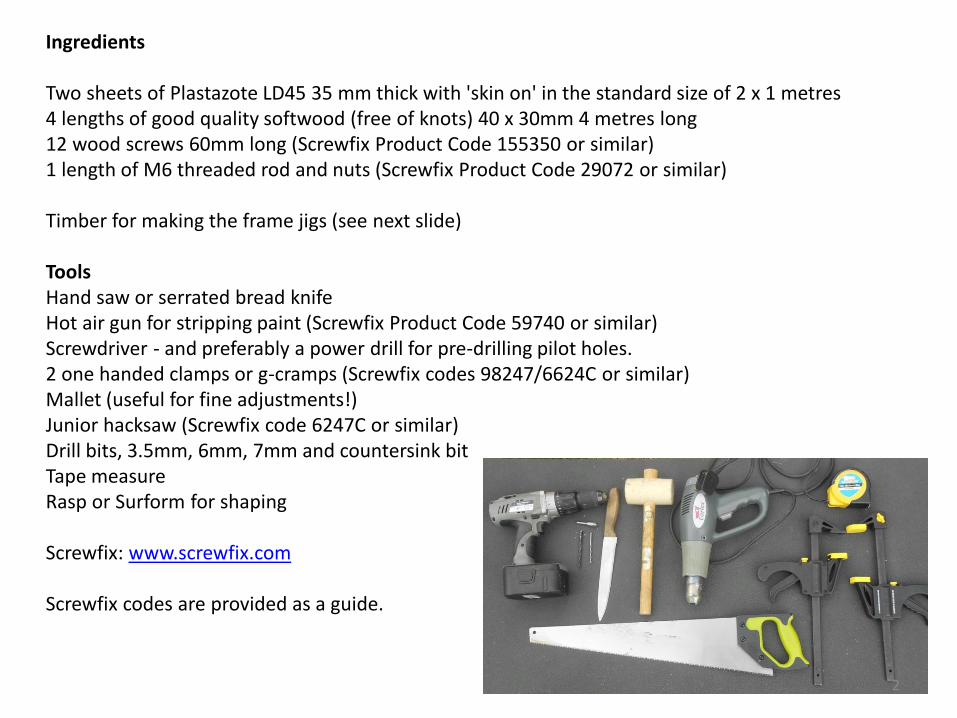
Ingredients Two sheets of Plastazote LD45 35 mm thick with 'skin on' in the standard size of 2 x 1 metres 4 lengths of good quality softwood (free of knots) 40 x 30mm 4 metres long 12 wood screws 60mm long (Screwfix Product Code 155350 or similar) 1 length of M6 threaded rod and nuts (Screwfix Product Code 29072 or similar) Timber for making the frame jigs (see next slide) Tools Hand saw or serrated bread knife Hot air gun for stripping paint (Screwfix Product Code 59740 or similar) Screwdriver - and preferably a power drill for pre-drilling pilot holes. 2 one handed clamps or g-cramps (Screwfix codes 98247/6624C or similar) Mallet (useful for fine adjustments!) Junior hacksaw (Screwfix code 6247C or similar) Drill bits, 3.5mm, 6mm, 7mm and countersink bit Tape measure Rasp or Surform for shaping Screwfix: www.screwfix.com Screwfix codes are provided as a guide.
2
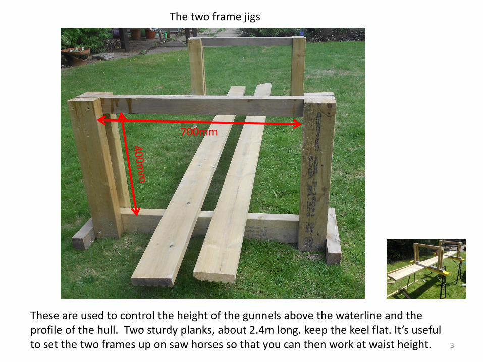
700mm
The two frame jigs
These are used to control the height of the gunnels above the waterline and the profile of the hull. Two sturdy planks, about 2.4m long. keep the keel flat. It’s useful to set the two frames up on saw horses so that you can then work at waist height. 3
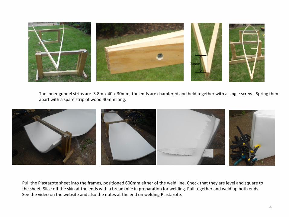
The inner gunnel strips are 3.8m x 40 x 30mm, the ends are chamfered and held together with a single screw . Spring them apart with a spare strip of wood 40mm long.
Pull the Plastazote sheet into the frames, positioned 600mm either of the weld line. Check that they are level and square to the sheet. Slice off the skin at the ends with a breadknife in preparation for welding. Pull together and weld up both ends. See the video on the website and also the notes at the end on welding Plastazote.
4
70mm
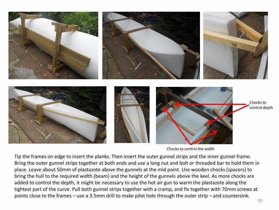
Tip the frames on edge to insert the planks. Then insert the outer gunnel strips and the inner gunnel frame. Bring the outer gunnel strips together at both ends and use a long nut and bolt or threaded bar to hold them in place. Leave about 50mm of plastazote above the gunnels at the mid point. Use wooden chocks (spacers) to bring the hull to the required width (beam) and the height of the gunnels above the keel. As more chocks are added to control the depth, it might be necessary to use the hot air gun to warm the plastazote along the tightest part of the curve. Pull both gunnel strips together with a cramp, and fix together with 70mm screws at points close to the frames – use a 3.5mm drill to make pilot hole through the outer strip – and countersink.
Chocks to control the width
Chocks to control depth
55

Chock both ends up otherwise the keel will curl downwards at the bow and stern. In this case leaving 200mm below the gunnel strip at the stern and 300mm at the bow.
Put three more 70mm woodscrews, evenly spaced, through the gunnel strips at both sides and ends to pull these tightly together. Before fitting the screws, check that the inner and outer gunnel strips are the same distance from the top edge of the plastazote sheet, otherwise they will not line up – and the screws might miss!
6
Next drill a 7mm hole in from each side at both bow and stern. These need to lined up carefully and avoid the screw holding the ends of the inner gunnels together. Run through a length of 6mm threaded rod and fits nuts and washers. Trim off the excess thread later.

Okay, you now have the opportunity to be a bit creative with the shape. In this case there is a swept up bow (useful for rough water) and a narrow vee cut in the keel at the bow and stern to provide for more ‘rocker’ (the curve of the keel). Also the plastazote has been trimmed and thinned to give a sharper bow and stern. Ensure that the surfaces are trimmed so that they fit together without strain – much easier to weld. Once welded, shape with a rasp or Surform tool then smooth with glass paper.
7
Shaping up!

8
Hull shapes
All of these hulls were made without the frame jigs and take their shape from the stiffness of the gunnel strips
Both canoes were make in the frame jigs – and in both with less ‘freeboard’ (the depth of height of the gunnels above the water, so that they are easier to paddle – in both cases the sheet width was reduced to 750mm. The black hulls would be suitable for rowers of 60 kilos or less; for heavier rowers, more freeboard is required so the orange hull uses the full 1000mm sheet width, A flatter hull bottom will be more stable, a more U shape will give a stiffer and faster hull shape – but at the expense of stability. If you are uncertain, start with a full-width sheet. It’s easy to lower the gunnel trips and trim of the excess – but less easy to weld some more on!

9
Welding Plastazote
It’s important to practise welding with scraps. If necessary, cut some from the ends of the sheet – the sheet with skin on is about 4.1m long so there is some to spare. If your supplier will weld the two sheets together for you, this is much easier.
When welding aim to direct the heat gun to heat the inner parts, not the edges that will tend to collapse. Press the surfaces tightly together. If successful a small ridge will appear at the joint. If overheated the area of the joint will become very soft and it will be difficult to apply pressure to the two surfaces. Holes can be filled with flakes of plastzote, heated gently and pressed in with a wooden spoon.
Area to be heated
10
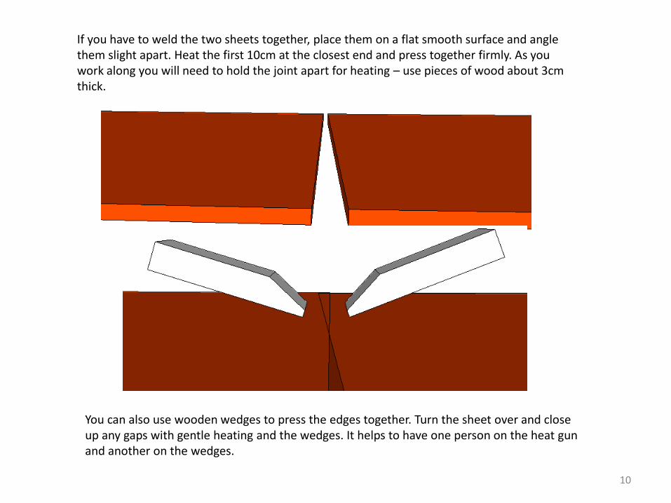
If you have to weld the two sheets together, place them on a flat smooth surface and angle them slight apart. Heat the first 10cm at the closest end and press together firmly. As you work along you will need to hold the joint apart for heating – use pieces of wood about 3cm thick.
You can also use wooden wedges to press the edges together. Turn the sheet over and close up any gaps with gentle heating and the wedges. It helps to have one person on the heat gun and another on the wedges.

Swivels can be bought new from boat suppliers but at £25 per swivel (sometimes called a 'gate') and £16 for the pin, these are expensive items (http://www.rowingcentre.co.uk/parts/006_rig.php). The swivel shown is made from 300mm x 25mm x 2.5mm stainless steel. Aluminium could be used but would need to be a thicker section, say 30mm x 4mm. The hinge is stainless steel and available as a pair from Screwfix for £3.99 (http://www.screwfix.com/p/ball-bearing-hinge-polished-stainless-76mm-1pr/75932). The wooden insert is made to fit the oars and needs a 4 degree taper to provide the correct stern pitch on the oar. The angle bracket connecting the swivel assembly to the rigger needs to be 4mm thick stainless steel or 6mm aluminium. Note: the two swivels must be 'handed' i.e. a right hand version and a left hand version.
Swivels (rowlocks) and riggers
The wing rigger shown here is made from 30mm Iroko but 50mm softwood is also suitable. The angle is 45 degrees and the centre points of the hinges (pins) should be around 158cm apart. The lowest point of the swivel needs to be at least 15cm above the seat.
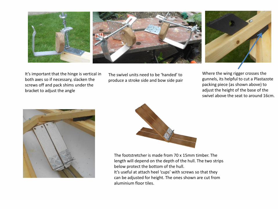
It’s important that the hinge is vertical in both axes so if necessary, slacken the screws off and pack shims under the bracket to adjust the angle
Where the wing rigger crosses the gunnels, its helpful to cut a Plastazote packing piece (as shown above) to adjust the height of the base of the swivel above the seat to around 16cm.
The footstretcher is made from 70 x 15mm timber. The length will depend on the depth of the hull. The two strips below protect the bottom of the hull. It’s useful at attach heel ‘cups’ with screws so that they can be adjusted for height. The ones shown are cut from aluminium floor tiles.
The swivel units need to be ‘handed’ to produce a stroke side and bow side pair

13
The sliding seat unit using fixed castors
The unit sits in the bottom of the boat and is moved backwards or forwards to suit the leg length of the rower.
Guide
The guide, fixed to the underside of the seat, needs about 2mm clearance The seat uses fixed castors (Screwfix Product Code: 69497)
Turn button
900mm
Two Plastazote strips about 100 x 50mm Fixed with screws and washers

14
Welding the hull with a hot air gun
The completed prototype Testing at Wokingham Canoe Club
This is a ‘Freestyle’ type of kayak made from Plastazote This is still in development . Plans and instructions will be available soon

15
For more information see: www.theopenboat.org Or contact: [email protected] For a related project, a self build rowing machine, See: http://openergo.webs.com/ Biographical notes: I'm a former lecturer in the Department of Design and Technology at Loughborough University, and Sub Dean of the Faculty of Technology at the UK Open University. Currently I'm a FISA Development Coach and British Rowing Coach Educator. Publications related to rowing:
Know the Game: Rowing http://www.amazon.com/Rowing-Know-Game-Amateur-
Association/dp/0713684313/ref=sr_1_1?ie=UTF8&qid=1453464262&sr=8-1&keywords=know+the+game+rowing
The Complete Guide of Indoor Rowing (with Charlie Simpson) http://www.amazon.co.uk/s/ref=nb_sb_ss_c_0_28?url=search-
alias%3Dstripbooks&field-keywords=the+complete+guide+to+indoor+rowing&sprefix=the+complete+guide+to+indoor%2Caps%2C149
Advanced Rowing: Perspectives on High Performance Rowing (with Charlie Simpson) http://www.amazon.co.uk/Advanced-Rowing-International-Perspectives-Performance/dp/1472912330/ref=sr_1_1?ie=UTF8&qid=1453464616&sr=8-1&keywords=advanced+rowing
Free E-booklets Coaching Balance http://www.rowperfect.co.uk/product/balance-by-jim-flood-ebook-2/
The Ergonomics of Rowing http://www.rowperfect.co.uk/product/the-ergonomics-of-rowing-by-jim-flood-2/
A Manifesto to Improve Club Rowing for Beginners http://www.rowperfect.co.uk/product/the-ergonomics-of-rowing-by-jim-
flood-2/
Why Slow the Boat When You Can Make It Go Faster http://www.rowperfect.co.uk/product/why-slow-the-boat-jim-flood/