integrated expert system development environment with an
TRANSCRIPT
Computer Science and Systems Analysis
Computer Science and Systems Analysis
Technical Reports
Miami University Year
Integrated Expert System Development
Environment With an Automatic
Verification Feature: An Application To
Grinding Process
Yueyi YuMiami University, [email protected]
This paper is posted at Scholarly Commons at Miami University.
http://sc.lib.muohio.edu/csa techreports/30
DEPARTMENT OF COMPUTER SCIENCE & SYSTEMS ANALYSIS
TECHNICAL REPORT: MU-SEAS-CSA-1994-004
Integrated Expert System Development Environment With an Automatic Verification Feature: An Application
To Grinding Process Yueyi Yu
School of Engineering & Applied Science | Oxford, Ohio 45056 | 513-529-5928

Integrated Expert System Development
Environment with an Automatic Verification
Feature: An Application to Grinding Process
Yueyi Yu Systems Analysis Department
Miami University Oxford, Ohio 45056
Working Paper #94-004 Sept. 1994

INTEGRATED EXPERT SYSTEM DEVELOPMENT ENVIRONMENT WITH AN AUTOMATIC VERIFICATION FEATURE: AN APPLICATION TO GRINDING PROCESS
Final Report
Submitted to the faculty of Miami University
in partial fulfillment of the requirements for the degree of
Master of Systems Analysis Department of Systems Analysis
Miami University
Yueyi Yu Miami University
Oxford, Ohio 1994
COMMITTEE MEMBERS:
Dr. Mufit Ozden, advisor :
Dr. Alton Sanders, member:
Dr. Valerie Cross, member :

ABSTRACT
The concerns of this Master degree project are the implementations of an expert system
development environment and an application to manufacturing. The environment is given the
name of IDEA (Integrated expert system Development Environment with Automatic verification
feature), and it integrates an expert system shell with a rule base verification facility and a rule
base builder into a single program. The interface of IDEA has the look of a general purpose
computer language. The knowledge bases referenced by IDEA consist of LF-THEN rules with
the syntax of Object-Attribute-Value (O-A-V) triples and confidence factors. An application is
developed for grinding chattering diagnosis problems using the IDEA.
The verification facility of IDEA realizes the main functions of CHECK, a verification
tool, developed by T. Nguyen et al, 1987, so that it can identify some major problems of
inconsistency and incompleteness. Different from CHECK, IDEA uses a unique approach based
on rule tree algorithm to check for some logic problems in a rule base. IDEA also has the ability
to draw the rule tree on a computer screen. This report discusses the problems of inconsistency
and incompleteness in detail, including the influence of introducing confidence factors. Some
problems identified in this report are not reported before.
The rule base builder of IDEA uses some techniques that can greatly reduce errors in a
rule base during its input phase and greatly speed up the input work. First, the builder uses
templates for rule input to eliminate the possible syntax errors of rules. Second, it uses an O-A-
V file for declared O-A-V triples. By checking the O-A-V file and the O-A-V triples used in the
rule base, the problems of illegal O-A-V triples and unreferenced O-A-V triples can be
identified. Finally, it has the ability to automatically generate the ask-part of the rule base, so
that no errors will exists in the ask-part and the input work can be efficient.
Grinding chattering is a kind of abnormal phenomenon in a grinding process, which
greatly degrades the surface quality of the workpiece ground. The grinding chattering diagnosis
rule base gives complete answers for the causes of chattering for external cylindrical grinding.
This report describes the rule base development work and its related grinding knowledge.

TABLE OF CONTENTS
3.1 Rule Base Builder ---------------------------------------------------------------------------- 16 3.1.1 Causes of Inconsistency and Incompieteness .................................. 16 3.1.2 Approaches ....................................................................... 16 3.1.3 Implementation ................................................................... 17

1. INTRODUCTION
The original objective of this research was to develop a knowledge acquisition environment for a
rule-based expert system and an application to manufacturing system. As the project progressed,
more emphasis was put on the expert system development environment. The environment is a
rule-based expert system shell integrated with editing and verification facilities. The
manufacturing application was developed with the guidance of Associate Professor Myron.
Schmenk, from the Manufacturing Engineering Department.
This report is intended to provide a description of the expert system development
environment developed in the Master degree project, and to discuss its associated concepts and
the techniques. Chapter 2 introduces the concept of verification and discusses the potential
problems in a knowledge base. Chapter 3 describes the work of developing the environment and
explores the possible approaches. Chapter 4 describes the developing work for the grinding
chattering diagnosis rule base.
In the following sections, the general concepts and terminology of expert systems and
knowledge representation formalisms are introduced, the domain selection work is described, and
a general description of the expert system environment developed is provided.
1 .1 Ex~ert Systems
Early expert systems arose in the late 1960's to the early 1970's. Well-known examples are
* DENDRAL, 1965, developed to identify the chemical molecular structures;
MACSYMA, 1969, the first mathematics expert system; and
* MYCIN, 1973, an expert system for medical diagnosis.
Since then, expert systems have experienced tremendous growth and popularity. Today, their
applications are 'found in all fields, including science, medicine, military, business, and
engineering.

Definition. A variety of definitions for expert systems has been offered by several prominent
researchers [11, 12, 13, 19. 201. In summary, an expert system is a computer program that
emulates the decision-making process of human domain experts. Based on the definition, expert
systems should have two basic features:
1. The problem that an expert system intends to solve is difficult enough to require
significant human expertise, usually in a narrow domain, for its solution.
2. Expert systems are symbolic reasoning oriented. Usually, judgments, rules of thumb,
and intuition are embodied in an expert system.
I4 Structure. The basic structure of an expert system is shown in Figure 1.1. The working
memory contains the specific factsldata for a problem and the intermediate to final results
produced by the system. The inference engine is the overall controller for the system. It
provides reasoning methods and produces conclusions, advice and explanations for the end use.
The knowledge base contains required expertise. The knowledge acquisition facility is the
Knowledge Engineer
Domain Knowledge Knowledge Expert
' acquisition base
\ facility 1
Figure 1.1 The structure of expert system
interface between domain experts and knowledge engineers. It includes methods and programs
for developing, verifying and validating a knowledge base. Another important concept is expert

system shell, first introduced by MYCIN. Usually, an expert system shell consists of a user
interface and an inference engine. Hence, the problem specific knowledge base is separated from
the solution search procedures of the system.
In principle, any consistent formalism in which the domain knowledge can be expressed can be
used for knowledge base building. However, the most popular formalisms are production rules,
semantic nets and frames. Their advantages and disadvantages are discussed below.
II Production Rules. Because most of production rules have the IF... THEN format, they are
also called IF-TLIEN rules (the terminology production rules and IF-THEN rules will be used
alternately below). The corresponding expert systems are called rule-based expert systems.
Production rules have remained the most frequently used knowledge representation
scheme. This resulted from their three significant advantages:
1 . Naturalness. A rule-based system mimics human experts in a natural way. IF-THEN
rules could be easily understood and accepted by non-computer-oriented experts.
This is a great benefit in knowledge acquisition.
2. Modularity. A rule base is highly modular. Each rule can be added, modified or
deleted independently of other rules.
3. Uniformity. All knowledge in the rule base is represented in exactly the same way.
This eases the work of rule base development.
On the other hand, production rules also have the following disadvantages:
1 . Flatness. This formalism is quite flat and great numbers of rules are needed to model
a real-world domain. This causes inefficiency when the rule base is executed.
2. Diflcultyfor tracing. Usually, knowledge in a rule base is not well organized, so it is
often difficult to trace over the rule base. Efforts are made in this project to address
this problem by introducing rule tree (see Section 3.3).
3. Non-descriptive. It is not natural to represent descriptive knowledge, such as the
characteristics of an automobile, by using IF-THEN rules.

W Semantic Nets and Frames, Semantic nets and frames are two similar formalisms in which
large sets of concepts and facts are directly attached to entities which they describe. Semantic
nets and frames have the following advantages over production rules:
1 . Inheritance. Entities' properties could be inherited from their ancestors. The
formalisms are deep in nature and the knowledge bases are easy to trace.
2. Eficiency. Because facts are directly connected to related nodes or frames', the search
time for a particular fact can be greatly reduced.
Frames also have the following additional advantages:
1. Object-oriented nature. Frames are actually objects, so they are adopted in a natural
way by object-oriented programming. This is the major reason why frames are
steadily growing in popularity.
2. Procedure attachment. As mentioned above, procedures can be attached in a frame.
This feature greatly expands the application domains for frame-based systems.
The disadvantages of semantic nets and frames include:
1. Dificulty of interpretation. Because the knowledge is stated in a less English like
way in semantic nets and frames, and there is lack of interpreting standards, the
knowledge bases are difficult to understand by domain experts and may be interpreted
in different ways.
2. Non-heuristic. It is difficult to represent heuristic knowledge without using IF-THEN
rules.
' 1.3 Domain Selection
Selection of an appropriate domain is very important for an expert system, because it has
significant influence over the knowledge representation scheme, the knowledge acquisition
facilities and the inference engine. The domain chosen should meet the basic requirements:
+ The domain is narrow enough to ensure the success of the project.
* The problems in the domain require symbolic reasoning for their resolutions.
+ There exists at least one expert who is available and willing to work on the project.
in our case, a tot of effort has been spent in surveying the literature for an application
area. The domain was finally limited to grinding problems, mainly because Associate Professor
M. Schmenk, a metal cutting expert, showed interest in development of the knowledge base.
Two possible tasks in grinding were identified:
1. grinding parameters selection; and
2. quality problem diagnosis.
The first task is suitable for data-driven expert systems but involves numerical calculations. The
second task is suitable for goal-driven expert system and involves only symbolic reasoning.
Therefore, the latter one is found to be more appropriate for the project. To further narrow the
domain, the final task was chosen as grinding chattering diagnosis. Grinding problems are
discussed in more detail in Chapter 4.
IDEA (Integrated expert system Development Environment with Automatic verification feature)
is the expert system development environment developed in this project, using Prolog. The
motivation for IDEA is to develop a prototypal expert system environment that would have the
appearance of a general purpose computer language. In other words, the objective for IDEA is to
have functions analogous to the editing, compiling, debugging and running options in C or
Pascal.
.I Selection of Knowledge Representation Formalism. IDEA uses IF-?HEN rules to represent
the knowledge. This decision was simply triggered by the availability of an inference engine that
could be utilized for a rule-based system built in Prolog.

II Syntax. A sample of toy rule base is shown in Appendix A. The ruie base is headed by a
top-goal "problem". This means the top-goal of the inference engine is to find what the
"problem" is.
The body part of the rule base consists of IF-WEN rules. Each IF-'THEN rule in turn
consists of a rule ID, le8-hand side (LHS) and right-hand side (RHS), and has the syntax:
Rule <RulelD>
IF [not]<Objectl> <Attribute1 > [<Value1 >]
[AND [not]<Object2> <Attribute2> [<Value2>]
AND [not]< ObjectM> <AttributeM> [< ValueM>]]
THEN <ObjectN> <AttributeN> [<ValueN>] [cf <CF>].
Where the contents inside < > are supplied by the knowledge engineer; the contents inside [ ] are
optional; the cf stands for confidence factor; cf has a value in the range of [-loo, 1001; the
default value for Value is yes; the default value for cf is 100. The LHS consists of IF conditions.
An IF condition includes an object-attribute-value triple (0-A-V triple) following an IF or an
AND. For example, the LHS of the first rule in Appendix A is:
IF engine turn-over
AND auto battery bad
The RHS consists of only a THEN conclusion. The THEN conclusion in turn includes a THEN,
an 0-A-V triple and a confidence factor. There are two kinds of IF conditions: IF conditions
that can be matched with other rules' THEN conclusions and IF conditions that can not be
matched. The latter IF conditions are given the name of leaf IF conditions. Note that an Object-
Attribute pair could be a variable. Because the inference engine used in IDEA does not have the
ability to deal with variables, they are not introduced in the application rule base.
Following the rules is the ask-part of the rule base. This part consists of queries to
acquire known basic facts from the end user. Each query corresponds to a leaf IF condition.

2. KNOWLEDGE BASE VERIFICATION
Verification is a part of the evaluation work for a written knowledge base. Different from
validation, verification does not deal with expertise, instead, it checks for only the faultiness in
an abstract knowledge base. In other words, a verified knowledge base is the one built in a
"right" way, but not necessarily a "right" one itself.
T. Nguyen, Walton, Perkins and Pecora (1987) wrote that the problems in a knowledge
base can be classified as inconsistency and incompleteness [I]. For inconsistency, they
identified the potential problems as redundant rules, conflicting rules, subsumed rules,
unnecessary IF conditions, and circular rules. For incompleteness, they identified the potential
problems as unreferenced attribute values, illegal attribute values, unreachable conclusions, and
dead-end IF conditions. Gonzalez and Dankel (1993) described the similar problems [13].
It should be pointed out that the potential problems in a knowledge base can be detected
only if the syntax of knowledge representation is sufficiently restricted. More important,
different kinds of knowledge base will have different kinds of problems. For the backward-
reasoning IF-THEN rules used in IDEA, we identified the problems :
1. syntax error
2. illegal 0-A-V triples
3. inconsistency
4. incompleteness
The first one is self-explanation. The second one refers to the 0-A-V triples which have not
been declared. In the case of IDEA, the illegal 0-A-V triples are the triples that are not included
in the 0-A-V file (see Section 3.1). This problem is caused by typing mistakes andtor misusing
terminology. The last two are discussed in more detail in the next two sections. This discussion
attempts to be as complete as possible, including some inconsistency forms that are not reported
before as well as the influence of introducing confidence factors, but it is limited in the scope of
pure theory. The implementation work for the verification facility will be discussed in the next
chapter. Again, the discussion is based on the rule base syntax defined in Section 1.4.

2.1 Checkina for Consislency
Inconsistency refers to a logical incorrectness in a rule base. Six potential problems ire
identified:
H Redundant Rules. Two rules are redundant if they have actually the same IF conditions and
the same THEN conclusion. For example, consider the two rules that follow:
Rule I
IF not engine turn-over
AND auto battery bad
THEN problem auto battery.
Rule 2
IF car battery bad
AND not engine turn-over
THEN problem car battery.
These two rules would be redundant, because they actually referred to the same conditions and
the same conclusion, though Rule 2 used "car battery" instead of "auto battery" and its IF
conditions were in a different order.
It should be pointed out that the above definition, based on T. Nguyen et a1 and Gonzalez
et al, is only a special case of redundant rules. In most cases, a redundant rule would be the one .
that can be derived from the other two or more rules. For example, with the notation of predicate
calculus, consider the set of rules that follow:
Apparently the first rule can be derived from the other two rules. Though this case is still quite
simple, it is already quite difficult to be detected by programs.
Note that with the introducing of confidence factors, two 'ITEN conclusions that have
the same 0-A-V triple but different confidence factors should be regarded as different

conclusions. For example, if rule 1 and rule 2 have different confidence factors, they should not
be regarded as redundant rules. Instead, they become conflicting rules (discussed below).
Although redundancy usually does not cause logic problems, it might affect efficiency.
In such cases, it is better to eliminate the redundancy.
Conflicting Rules. Two rules are conflicting if they have actually the same F conditions but
different THEN conc1usions. For example, consider the two rules that follow:
Rule 3
IF engine turn-over
AND auto radio weak
THEN auto battery bad.
Rule 4
IF engine turn-over
AND auto radio weak
THEN gas run-out.
These two rules are conflicting, because given the same IF conditions, different conclusions are
derived. Conflicting rules could cause serious logic problems. Usually only one rule among the
conflicting set is correct. The above description of conflicting rules is suitable for both cases of
with or without confidence factors. The way to fix this problem is to identify the incorrect
conflicting rules and eliminate them.
Note that conflicting rules do not necessarily cause logic problems. Under some
circumstances, conflicting rules are legal and they work as a single rule in which the THEN
conclusion has OR logical relations:
Rule <RuleZD>
IF <condition 1 >
AND <condition 2>
AND <condition m>
THEN <conclusion 1 >
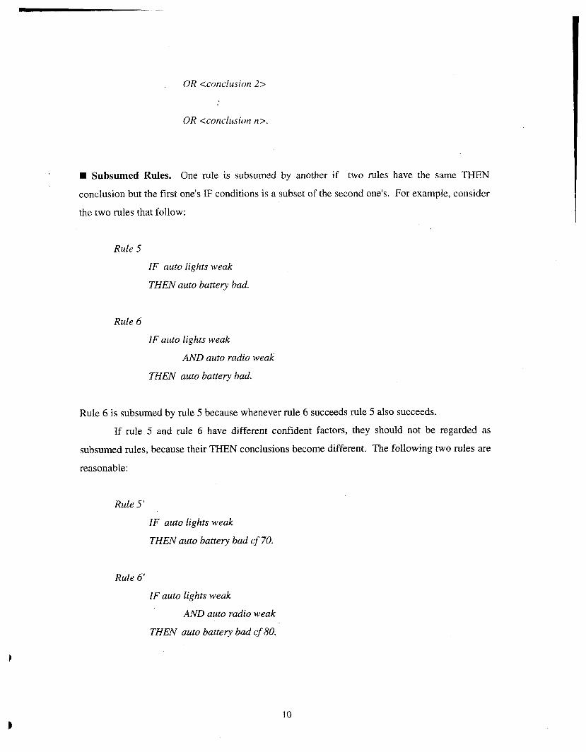
Subsumed Rules. One rule is subsumed by another if two rules have the same THEN
conclusion but the first one's IF conditions is a subset of the second one's. For example, consider
the two rules that follow:
Rule 5
IF auto lights weak
THEN auto battery bad.
Rule 6
IF auto lights weak
AND auto radio weak
THEN auto battery bad.
Rule 6 is subsumed by rule 5 because whenever rule 6 succeeds rule 5 also succeeds.
If rule 5 and rule 6 have different confident factors, they should not be regarded as
subsumed rules, because their THEN conclusions become different. The following two rules are
reasonable:
Rule 5'
IF auto lights weak
THEN auto battery bad cf 70.
Rule 6'
IF auto lights weak
AND auto radio weak
TMEN auto battery baa' cf 80.

The second IF condition in rule 6' could be purposely added to change the confidence. Because
the second IF condition favors the THEN conclusion, rule 6' has a larger confidence factor value
than that of rule 5'. Otherwise, a logic error must exist in the rule base.
Subsumed rules will cause logic errors. At most, only one rule among the subsumed set
is correct. The way to fix this problem is to identify the right one and to delete the rest of the
rules in the subsumed set.
H Unnecessary IF Conditions. Two rules contain unnecessary IF conditions if they have the
same THEN conclusion , a subset of IF conditions in the first rule is the negation of the
correspondent IF conditions in the second rule, and all other IF conditions are equivalent. For
example, consider the two rules that follow:
Rule 7
IF engine turn-over
AND auto radio weak
THEN auto battery bad.
Rule 8
IF not engine turn-over
AND auto radio weak
THEN auto battery bad.
The first IF condition in both rules is unnecessary, because the THEN conclusion will be true if
only the second IF condition is true.
Unnecessary IF conditions will effect efficiency, although it does not cause logic errors.
The way to fix this problem is to delete the unnecessary IF conditions and collapse the two rules
into one. For example, the above two rules could be collapsed into the single rule
Rule 7'
IF auto radio weak
THEN auto banery bad.
If rule 7 and rule 8 have different confidence factors, one of the first LF condition could
be still needed, so treat the two rules, as the case of rule 5'and rule 6'.
T. Nguyen et a1 pointed out the second form of unnecessary IF conditions [ I]. With the
notation of predicate calculus, this form can be represented as:
a(x) and not b(x) -> cfx); b(x) -> c(x).
To illustrate this consider the following two rules:
Rule 9
IF auto radio weak
AND not auto lights weak
THEN auto battery bad.
Rule 10
IF auto lights weak
THEN auto battery bad.
In this case, the second IF condition in rule 9 is unnecessary, but two rules are still needed. If
rule 9 and rule 10 have different confidence factors, they could be reasonable.
There is still the third form of unnecessary IF conditions that is not reported. With the
notation of predicate calculus, this form can be represented as:
a(x) and b(x) -> c(x); a(x) -> b(x).
To illustrate this, consider the following set of rules:
Rule 11
IF auto radio weak
AND auto battery bad
THEN problem auto battery.
Rule I2
IF auto radio weak
THEN auto battery bad
In this case, the first IF condition in rule 11 is unnecessany, even if the two rules have different
confidence factors. However, the two rules are still needed.
E Circular Rules. A set of rules is circular if they form a closed reasoning chain. The
following two rules &e an example of circularity:
Rule 13 '
IF auto radio weak
THEN auto battery bad.
Rule 14
IF auto battery bad
THEN auto radio weak.
This loop is apparent. But if a loop is formed by a long reasoning chain, it will be very difficult
to be detected by a knowledge engineer.
Gonzalez and Dankel (1993) reported another form of circularity [13]. Consider the
following rule:
Rule 15
IF X is bald
THEN X's son is bald.
If X = John and John is bald, this rule will derive that John's son is bald too. This conclusion in
turn satisfies the rule's only IF condition and will derive that John's son's son is bald, and so
forth.
The above descriptions sf circular rules are suitable for both cases of with or without
confidence factor. Circularity will lead the computer into an infinite loop, so it should be
avoided.

ill Duplieated 0 - A Pairs. This problem was identified when the grinding chattering diagnosis
rule base was being tested. Two 0-A pairs are duplicated if they are identical and belong to the
same rule's IF conditions. For example, consider the following rule:
Rule 16
IF engine idle-speed >1000rpm
AND engine idle-speed < 2000rpm
THEN engine idle-speed normal.
Rule 16 coitains a duplicated 0-A pair because "engine idle-speed" appeared twice in IF
conditions. The consequence of the duplicated 0-A pair is the user will be asked twice for the
same question:
engine idle-speed lr<lOOOrpm, > 1000rpm, <2000rpm, >2000rpm] ?
The user will be confused by the question and probably will choose an unwanted answer. For
example, the user might choose the answer ">lOOOrpmN twice. This rule should be modified as:
Rule 16'
IF engine idle-speed 1000-2000rpm
THEN engine idle-speed normal.
When the inference engine looks at rule 16', it will ask the user:
engine idle-speed [< 1 000rpm, 1000-2000rpm, >2000rpm] ?
In this time, the user will not be confused any more.
2.2 Checkina for Com~leteness
hcompleteness refers to the missing of rules, fact-asking and/or 0-A-V triples. Incompleteness
is not affected by confidence factors. Three potential problems are identified

Unreferenced 0-A-V Triples. A declared 0-A-V triple is unreferenced if it is not covered by
any rules. Unreferenced 0-A-V triples usually imply missing rules or IF conditions. The rules
or F conditions that cover the unreferenced 0-A-V triples should be added into the rule base,
otherwise these 0-A-V triples should be removed from the list of declared 0-A-V triples.
Unaskable IF Conditions. Unaskable IF conditions are usually called dead-end IF conditions
or dead-end rules. But the terminology "unaskable F conditions" is easier to be understood by
the end user. An IF condition is unaskable if it is not referenced in any other .rule's THEN
conclusion and is not referenced in the ask-part of the rule base. Unaskable IF conditions might
cause run time errors, so the correspondent queries should be added to the ask-part.
Unreachable Rules. A rule is unreachable if it is not linked with the top-goal by any
reasoning chain. Unreachable rules are usually caused by missing rules or IF conditions, or
caused by typing errors, so they might imply the existence of logic problems in the rule base. In
this case, the missing rules or IF conditions should be added to the rule base. Sometimes, an
unreachable rule could be a trash rule. In this case, it should be eliminated from the rule base.
3. fMPLEMENTATlON OF IDEA
IDEA consists of a rule base builder, a verification facility, a rule tree building facility, and an
inference engine.
3.1 Rule Base Builder
The rule base builder of IDEA consists of a rule base editor and an ask-part generator. There are
two main goals for the development of the builder. First, the builder should be a useful tool for
the user to build up a rule base with minimum errors. Second, the builder should be efficient.
To realize the first goal, the causes of potential problems are analyzed and appropriate
approaches for eliminating these problems are adopted. The second goal is mainly guaranteed by
the ask-part generator.
3.1 .I Causes of Inconsistency and Incompleteness
For an inconsistency andfor incompleteness rule base, four major causes are identified:
1. Typing errors. Typing errors are the most common errors and the major source for all
kinds of problems discussed in Chapter 2.
2. Misusing 0-A-V triples. Misusing 0-A-V triples is the direct cause for illegal 0-A-V
triples and may be responsible for some inconsistency and incompleteness problems.
They in turn could be the results of typing errors.
3. Missing rules, IF conditions andlor fact queries. Missing directly cause
incompleteness in rule base. It could also cause conflicting or subsumed rules.
4. Logic errors. Logic errors are the cause for inconsistency.
3.1.2 Approaches
The rule base builder follows the rule of thumb that all potential problems should be detected and
eliminated as early as possible. Its goal is to prevent, detect and eliminate syntax errors, illegal

0-A-V triples, unreferenced 0-A-V triples and unaskable IF conditions when a rule base is in its
editing phase.
In order to prevent syntax errors, our approach is to use a template for rule input. With
the ruIe template, the rule base developer is forced to type in syntactically correct rules.
For the problems of illegal and unreferenced 0-A-V triples, a special file, called 0-A-V
file, is introduced. An 0-A-V file consists of 0-A-V triples to be declared. An 0-A-V triple has
the syntax:
Object, Attribute, [Valuel, Value2, ..., ValueN].
When an 0-A-V triple has been entered by the rule base developer, the editor will search the 0-
A-V file for the same 0-A-V triple. If the 0-A-V triple is not found, the rule base developer will
be warned. When the rule base is saved, the set of referenced 0-A-V triples and the set of
declared 0-A-V triples will be compared. If any declared 0-A-V triple is not referenced, the rule
base developer will also be warned.
To eliminate unaskable IF conditions, the ask-part generator is developed. When a rule
base is saved, the generator will look up all IF conditions and determine if it is a leaf IF
condition. Then the generator will automatically write a fact query for each of leaf IF condition
onto the rule base file. In this approach, no rule will contain unaskable IF conditions,
meanwhile, no other error will exist in the ask-part of the rule base.
3.1.3 Implementation
First, a rule template is developed according to the syntax described in Chapter 1. The rule ID
could be either a number or a word, but must be unique. When an object or an attribute is
entered, the rule editor searches for the 0-A-V database to determine if it is a new 0-A pair. If it
is new, the user will be given options to create a new 0-A-V triple or to re-enter the 0-A pair.
When a value is entered, if it belongs to an existing 0-A-V triple, it will be checked if it is a
member of the value list; otherwise, it will not be checked. In the first case, if the value is new,
the user is again given options to create a new value or to re-enter it. When the user is prompted
to enter an object, all of the pre-declared objects are listed on the screen. The user can type in
only the index number instead of the whole object. This greatly saves typing work and reduces
typing errors. Similarly, when the user is prompted to enter an attribute, all of pre-declared
attributes that followed the object that was typed in are listed. When the user is prompted to
enter a value, the set of pre-declared values that belongs to the 0-A pair are listed.
Second, more editing functions are provided. If the user types in a rule ID that already
exists, he/she is given options to modify, delete or rename the rule, or to re-enter the rule ID.
Finally, when the user chooses to save the rule base file, the ask-part is automatically
generated. Meanwhile, illegal 0-A-V triples in the rule base and unreferenced 0-A-V triples in
the 0-A-V file, if exisit, are checked. If there are unreferenced 0-A-V triples, the user will be
informed whether it is the whole triple that is unreferenced or only some values that are
unreferenced.
3.2 Rule Base Verification Facilitv
The need for a rule base verification facility for IDEA is due to the fact that the rule base builder
is not capable of detecting inconsistency problems, though it can greatly reduce potential
problems. The rule base verification facility was developed to detect inconsistency and
unreachable rules.
Several verification tools have been reported since 1980's. One example is CHECK,
developed by T. Nguyen et al, 1987, for use with LES, a generic rule-based expert system
building tool [I]. CHECK is reported to be capable of detecting all problems described by the
developers (see Chapter 2).
PREPARE is another verification tool, implemented by Zhang and D. Nguyen, 1993
[14]. PREPARE used a special modeling methodology, called Predicate/Transition (Prn ) nets,
a subclass of Petri nets. Pr/T nets are also a graphical representation of first order predicate
logic. Pr/T nets are used to model the ruIe base so that it may be verified by detecting the
problem patterns associated with inconsistency and incompleteness.
3.2.1 Approaches
To detect redundant, conflicting, subsumed rules and unnecessary IF conditions, the approach
used in IDEA is similar to the one used in CHECK. For each rule in the rule base, the
verification facility compares it with the other rules one by one. If a rule is found to have the
same LHS, the facility will check if a redundant or conflicting rule exists. If a rule is found to
have the same RHS, the facility will check if a subsumed rule or an unnecessary F condition
exists.
For the problems of circular and unreachable rules, the approach is unique. This
approach is based on the fact that the rule bases referenced by IDEA are goal-driven rule bases.
Starting from the top-goal, the verification facility traces over the whole rule base and puts all of
the rules it encountered into a database. This database has a tree structure. The root node is the
top-goal. The leaf nodes are the rules that contain leaf IF conditions. Each node (rule) of the
tree in turn has a pointed4 structure:
poinier(~evel, RuleID, Children, History).
Where Children is a list containing the IDS of the rules the node points to; History is also a list
containing the IDS of the rules from the top-goal to the previous node. If a loop exists, it can be
detected by checking the History. The rules not covered by the database of pointed4 are
unreachable rules.
3.2.2 implementation
The actual work is a program that is capable of detecting the major problems described in
Chapter 2. These problems cover redundant rules, conflicting rules, subsumed rules, unnecessary
IF conditions, circular rules, and unreachable rules. This verification facility does not deal with
confidence factors, because the original scope of this project was merely to realize the basic
functions of CHECK.
For redundant rules, only the case illustrated by rule 1 and rule 2 in Chapter 2 is covered.
IDEA does not detect the rules that can be derived from the other two or more rules. Detecting
these rules might require considerable effort and consume considerable amount of memory space
and computing time. Considering that redundant rules do not cause logic errors, it is usually safe
without implementation of this function at this point.
For unnecessary IF conditions, IDEA covers only the case illustrated by rule 7 and rule
8. The case illustrated by rule 9 and rule 10 will be detected as subsumed rules, because the
program ignores the "not" in the second IF condition of rule 9. IDEA does not detect the case
illustrated by rule 11 and rule 12, because of the lack of time.
IDEA does not cover duplicated O-A pairs, because this problem was not identified until
the grinding chattering diagnosis rule base was tested. They should be detected by the rule base
builder.
For circular rules, the case illustrated by rule 15 dose not exists in the rule bases
referenced by IDEA, because these rule bases contain no variable, as mentioned in Section 1.4.
As to illegal O-A-V triples, unreferenced O-A-V triples and unaskable IF; conditions,
they are detected by the rule base builder.
3.3 Rule Tree
The capability of drawing a rule tree is a notable feature of IDEA. This feature provides the
user with
* a tool for the knowledge engineer to structurally build up a rule base;
a tool for the knowledge engineer to structurally test the rule base; and
* a tool for the end user to trace the rule base.
As a developing tool, the rule tree gives the knowledge engineer a graphical view of the structure
of a rule base. With the rule tree, the engineer knows the depth of the rule base, the number of
branches contained in the rule base, the logical interrelationships among the rules and even for
the rule loops. As a testing tool, the rule tree tells all the logical paths in the rule base. Using
these paths, the knowledge engineer can systematically test the rule base without any
unnecessary repetitive work. Moreover, the testing work can be independent of the inference
engine. As a tracing tool, the rule tree, together with the rule base, tells the end user how the
final conclusions are reasoned and why a suspected conclusion can not be reached.
In the subsections below, the alternative graphical representations of rule bases are
compared, the reason why rule tree is chosen is given, and the approach of drawing a rule tree is
discussed.
3.3.1 Graphical Representation of Rule Base
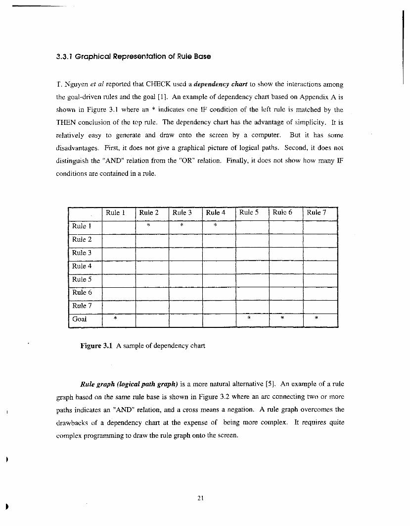
T. Nguyen et a1 reported that CHECK used a dependency chart to show the interactions among
the goal-driven rules and the goal [I]. An example of dependency chart based on Appendix A is
shown in Figure 3.1 where an * indicates one IF condition of the left rule is matched by the
THEN conclusion of the top rule. The dependency chart has the advantage of simplicity. It is
relatively easy to generate and draw onto the screen by a computer. But it has some
disadvantages. First, it does not give a graphical picture of logical paths. Second, it does not
distinguish the "AND" relation from the "OR" relation. Finally, it does not show how many IF
conditions are contained in a rule.
Figure 3.1 A sample of dependency chart
Rule graph (logicalpath graph) is a more natural alternative [5]. An example of a rule
graph based on the same rule base is shown in Figure 3.2 where an arc connecting two or more
paths indicates an "AND" relation, and a cross means a negation. A rule graph overcomes the
drawbacks of a dependency chart at the expense of being more complex. It requires quite
complex programming to draw the rule graph onto the screen.

Figure 3.2 A sample of rule graph
L 1 : engine turn-over; L2: auto high-beam weak;
L3: auto low-beam weak; LA: auto radio weak;
L5: smell gas; L6: gas gauge empty;
L7; gas gauge low; C1: auto battery bad.
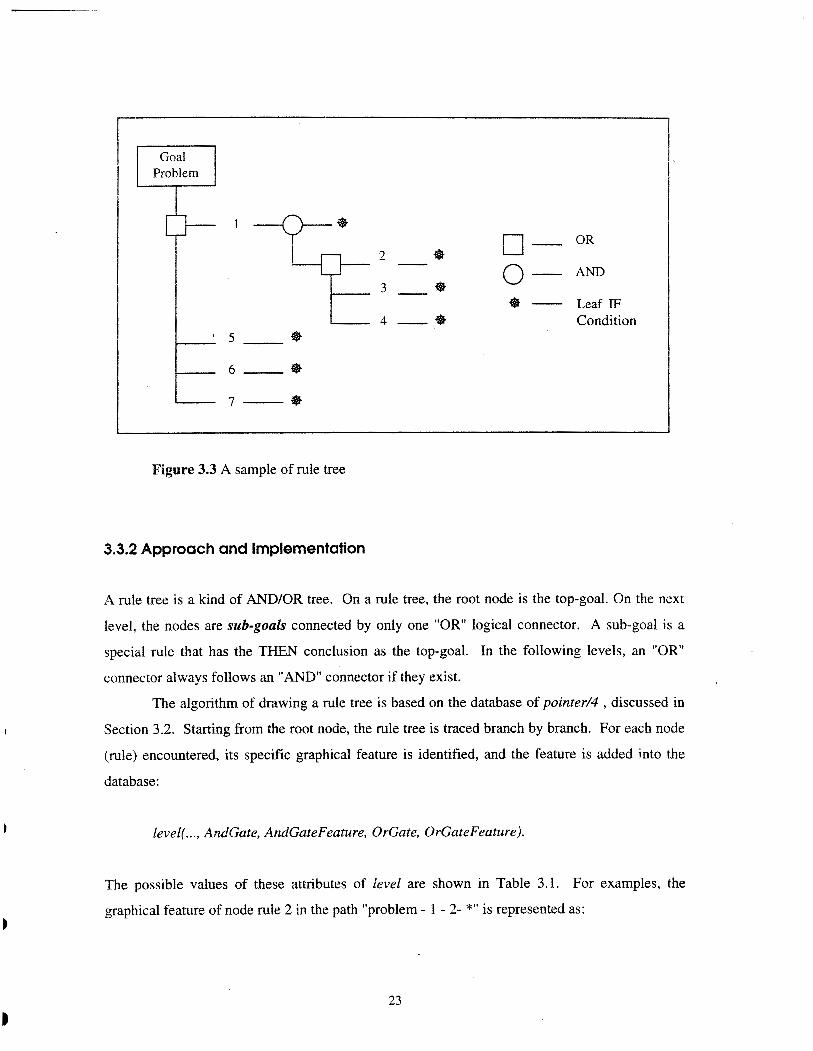
IDEA uses a rule tree to graphically represent a rule base. A rule tree is similar to a rule
graph and has almost the same advantages. The difference is that in a rule tree a node (rule) is
duplicated whenever it appears in a new path. It is easier to draw a rule tree than a rule graph.
This is the major reason why we chose a rule tree to graphically represent a rule base. Figure 3.3
shows a rule tree based on the same rule base as Figure 3.2.
0- 0" 2 - Q 0 - AND 3 - Q
@ - Leaf IF 4 - Q Condition
5 - Q
6 0
7 @
Figure 3.3 A sample of rule tree
3.3.2 Approach and Implementation
A rule tree is a kind of AND/OR tree. On a rule tree, the root node is the top-goal. On the next
level, the nodes are sub-goals connected by only one "OR" logical connector. A sub-goal is a
special rule that has the THEN conclusion as the top-goal. In the following levels, an "OR"
connector always follows an "AND" connector if they exist.
The algorithm of drawing a rule tree is based on the database of pointer/# , discussed in
Section 3.2. Starting from the root node, the rule tree is traced branch by branch. For each node
(rule) encountered, its specific graphical feature is identified, and the feature is added into the
database:
level( ..., AndGate, AndGateFeature, OrGate, OrGateFeature).
The possible values of these attributes of level are shown in Table 3.1. For examples, the
graphical feature of node rule 2 in the path "problem - 1 - 2- *" is represented as:
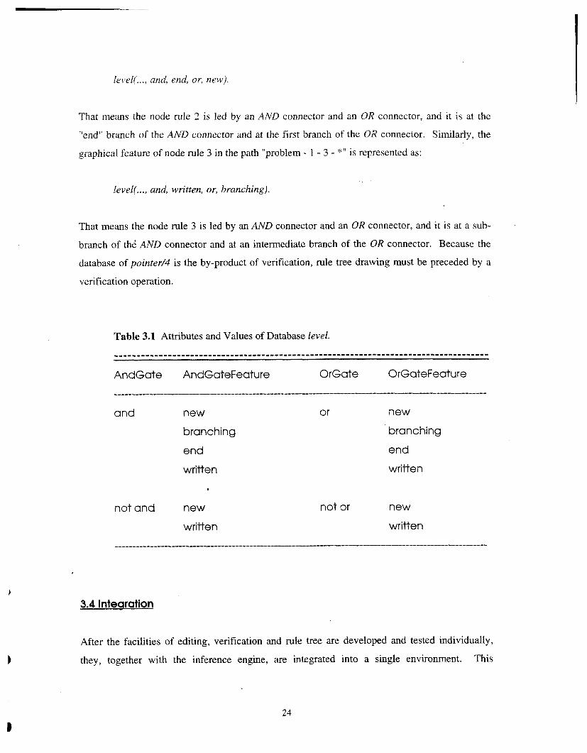
level! ..., and, end, or, new).
That means the node rule 2 is led by an AND connector and an OR connector, and it is at the
"end" branch of the AND connector and at the first branch of the OR connector. Similarly, the
graphical feature of node rule 3 in the path "problem - 1 - 3 - *" is represented as:
level( ..., and, written, or, branching).
That means the node rule 3 is led by an AND connector and an OR connector, and it is at a sub-
branch of thd AND connector and at an intermediate branch of the OR connector. Because the
database of pointed4 is the by-product of verification, rule tree drawing must be preceded by a
verification operation.
Table 3.1 Attributes and Values of Database level.
-----------------------------------------------------------------------------------*
AndGate AndGateFeature OrGate OrGateFeature
and new or new
branching branching
end end
written written
not and new not or new
written written .........................................................................................................
3.4 Intearation
After the facilities of editing, verification and rule tree are developed and tested individually,
they, together with the inference engine, are integrated into a single environment. This

environment is given the name IDEA, as mentioned above. IDEA has the user interface that has
a look of a general purpose computer language. In more detail, the interface has the options such
asfile, edit, veriJji (similar to "compile"), run, trace, help, and so on.
3.4.1 Inference Engine
The inference engine is based on the work implemented in the expert systems class, 1993,
lectured by Dr. Ozden. This work in turn is based on the textbook. Some modifications were
done and the interface was re-designed.
The inference algorithm used is goal-driven, backward-chaining. Starting from the top-
goal, the inference engine first checks if the top-goal is satisfied by an existing fact. If so, the
conclusion is immediately reached. Otherwise, the inference engine searches for the sub-goals.
The searching work is carried out by matching the top-goal with the THEN conclusions as the
sub-goals. When a rule fires (THEN conclusion matches), it will check for the IF conditions
contained by the sub-goal found. For each of the IF conditions, the inference engine will regard
it as a goal and do the above work over again. If an IF condition is neither satisfied by any
existing fact nor matched by any rule's 'REN conclusion, the inference engine will ask the user
to provide a basic fact that supports or rejects the IF condition. In both cases, the fact is added
into the working memory. If all the IF conditions contained in a rule are satisfied, the T I E N
conclusion is established. Otherwise, the rule is rejected.
The inference engine uses confidence factors of MYCJN to deal with uncertainty. If a
rule's IF conditions are supported by facts with confidence factors less than 100, the original
T m N conclusion confidence factor is replaced by the product of the minimum IF condition
confidence factor and the original TEEN conclusion confidence factor itself. For example, if we
have the rule:
Rule 17
IF auto radio weak
AND auto lights weak
THEN auto battery bad cf 90.
and the IF condition are supported by

auto radio weak cf 80;
auto lights weak cf 60.
The new conclusion should be
auto battery bad cf 54.
The additional functions of the inference engine are:
+ Tracing. This function is used to trace the reasoning process. The user will be told
which rule is called and if it is fired or rejected.
+ How Explanation. This function tells the user how the final conclusion is reached.
Why Explanation. When the user is prompted by a question, helshe can choose this
option to get the explanation for why this question is proposed.
* Why not Explanation. This function tells the user why an expected conclusion is not
reached.
3.4.2 Structure of Interface
IDEA has three modes: the main mode, the editing mode, and the run mode. Each mode contains
several push buttons. Each push button in turn may have several options. The hierarchical
structure of IDEA interface is shown in Figure 3.4.
The interface of IDEA is push-button-driven, somewhat different from ordinary menu-
driven interface. This interface has the following features:
1. Quick interface. Compared with a menu-driven interfaces, it may save one key stroke
to reach the same option.
2. Using modes. When the user chooses the edit option or the run option, it is likely that
helshe will stay in this option for a relatively long time. With the editing mode and
the run mode, the user can choose the related options more directly.
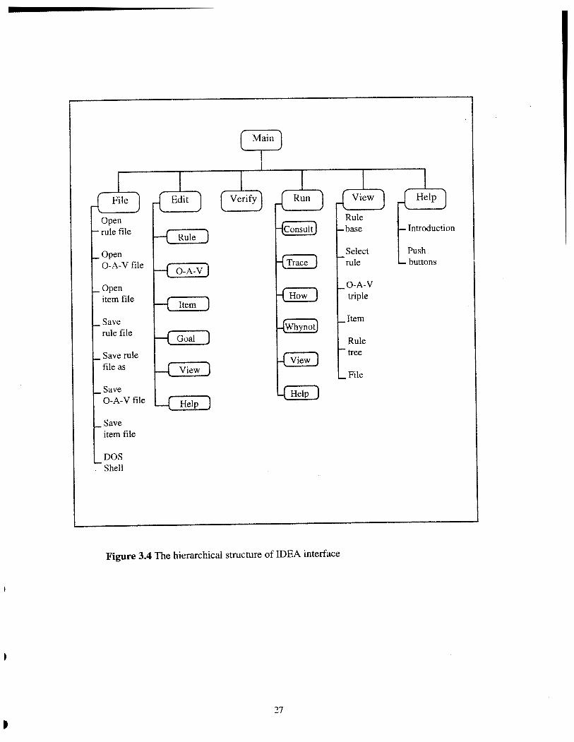
Figure 3.4 The hierarchical structure of IDEA interface
4. APPLICATION TO GRINDING PROCESS
This application is another major work accomplished in this project. The motivation is to build
up a prototype rule base that could be used to solve a real world problem using IDEA. As
mentioned in Chapter 1, the domain of this application is quite narrow so that it covers only the
chattering problems in external cylindrical grinding.
4.1 Grinding
Grinding is one of the major metal cutting process. The stocks on the surfaces of a work piece
are removed by a rotating grind wheel which is composed of tiny and hard bonded abrasive
grains. Each grain acts as a cutter. Grinding is usually used when the tolerance or finishing
requirements of the part to be machined are very high or the material is too hard to cut by other
metal cutting methods.
There are several reasons for building a grinding expert system:
1 . Lack of experts. The mechanism of grinding is much more complex than other
ordinary metal cutting methods, such as turning, shaping, milling, and so forth. When
turning, shaping or milling a work piece, only one or a few well-positioned and
shaped cutters cut materials at the same time. Whereas, in grinding process, there are
a large number of abrasive grains participating in the cutting process simultaneously.
The shape, position and size of each grain varies greatly. The consequence of the
complexity is the difficulty of fmding a grinding expert.
2. Cost. Grinding is an expensive and energy consuming process. The introducing of an
expert system is likely to have a significant payoff.
3. Importance. Grinding is typically used to process important parts with high quality
requirements, so it is worth having an expert system to provide process engineers with
a quality management tool.
There are many variations for the grinding process. The basic types of grinding are
surface grinding, external cylindrical grinding and internal cylindrical grinding, shown in Figure

4.1. External cylindrical grinding, for which the rule base is developed, is the one most
cornrnonliy used.
Figure 4.1 The types of grinding
4.2 Chattering
Chattering means vibrations occurred in a metal cutting process. For grinding processes, the
influences of chattering are significant:
1. It will generate chatter marks which greatly degrade the surface quality of the part
ground;
2. It might cause premature part failure as the result of fatigue;
3. It will create audible noise during the grinding process; and
4. It might disrupt lubrication.

There are tree types of vibrations that cause chatter marks: random vibration, forced vibration
and self-excited vibration [22]. In the rule base, the chattering caused by self-excited vibration
is called regenerative chatter.
Random vibration is caused by an occasionally created vibration source, for example, a
passing forklift truck or a passing train. If chatter marks are created by a random vibration, their
frequency could be irregular, and their amplitude could be variable. Random vibration does not
often cause problems, but its source is difficult to identify.
Forced vibration is caused by a fixed vibration source which could be either outside or
inside the grinder. The examples for an outside vibration source could be a punch press or an air
hammer. The inside vibration source is usually an unbalanced rotating component, such as an
unbalanced grinding wheel or an unbalanced idle wheel. If chatter marks are created by forced
vibration, their frequency will be synchronous with the vibration source, and their amplitude will
be constant.
The mechanism of self-excited vibration is quite complex. There are several
explanations for self-excited vibration, but none of them is commonly recognized. Generally
speaking, a self-excited vibration is agitated by a random event. For example, if the cutter
encounters a hard point in the material to be removed, it will cause the initial vibration. When a
self-excited vibration is stirred up, it can maintain itself by getting required energy from the
cutting process. Self-excited vibrations only occur when a cutting processing is going on. The
amplitude of chatter marks will become larger at the beginning of the cutting process until a
balance between the energy consumed and obtained is reached.
4.3 Rule Base
The actual work for the application to grinding process is a grinding chattering diagnosis rule
base that contains about forty rules (see Appendix B).
4.3.1 Implementation
The knowledge needed for building the rule base was mainly acquired from a grinding trouble-
shooting table, written by Lewis and Schleicher, 1976 [25] . Other resources include expertise
provided by Associate Professor M. Schmenk, materials provided by a grinding seminar,
sponsored by Institute of Advanced Manufacturing Science, Inc., 1993 [8]; and a chapter from a
text book, written by Yueyi Yu, 1991 [22]. The knowledge acquired was then translated into IF-
THEN rules
To write a well structured rule base, the most important thing is to group the rules
properly. With well organized rules, the end user can reach a conclusion with a minimum
number of questions answered, and the knowledge engineer will benefit when maintaining,
testing, and possibly expanding the rule base. Because the original trouble-shooting table is quite
flat, the chattering indications and causes were grouped according to the types of vibrations
before they were translated into rules. Some modifications for the original table were also done.
Ordering is another consideration for the rule base development. For some inference
engines, the order of rules will have an influence on efficiency. As a general principle, the rules
dealing with the most frequent events should be placed first. Although the inference engine used
for IDEA is not rule order sensitive, because it will look at all of possible conclusions, the rules
in the chattering diagnosis rule base were still ordered according to the principle. In more detail,
the rules about self-excited vibration were placed first, followed by the rules about forced
vibration and random vibration.
4.3.2 Result
After the rule base was built up, it was verified by the verification facility of IDEA, discussed in
Section 3.2. Through the verification, an inconsistency problem, duplicated 0-A pairs, which
was not reported before, was identified.
The rule base was then used to test the other facilities of IDEA. Through the testing
work, some problems with IDEA were also found and fixed.
Finally, the rule base was checked by Associate Professor M. Schmenk. According to
Associate Professor M. Schmenk, the rule base is moderately helpful for external cylindrical
grinding chattering diagnosis. This rule base has the following positive features:
1. it provides the end user with quite complete answers for the causes of chattering for
external cylindrical grinding;
2. the terms used in this rule base can be accepted by grinding process engineers; and
3. it is well structured, so it can be easily expanded to cover a wider range for grinding
diagnosis.
The limitations of this application are mainly due to the limited functions of the inference engine.
Because the deveIopment of an inference engine was beyond the original scope of this project,
some useful functions are not developed. Associate Professor M. Schmenk especially pointed
out the lack of the following functions:
1. Graphical View of Grinder. A picture of ,ginder will be very helpful for a less
experienced grinding process engineer to locate the source of chattering.
2. Undo option. The end user is likely to type in some wrong answers. An undo option
would be a great convenience for the end user to correct the errors.
3. Advises. After the source of chattering is identified, the program should provide the
end user with advice or instructions to fix the problem.

5. CONCLUSION AND FUTURE WORK
The major work accomplished in this project is the expert system development environment
IDEA and its testing in a grinding chattering diagnosis rule base. IDEA is a PC-based program
that has the following features:
1. Integrity. IDEA is a highly integrated expert system environment. It includes a rule
base builder, a rule base verification facility, and an inference engine, which are
incorp&ated in a single user interface.
2. Error avoiding and detecting. IDEA provides user with facilities to avoid syntax
errors, checks for typing mistakes, illegal 0-A-V triples and other inconsistency and
incompleteness problems.
3. Ask-part auto-generation. After rules are written, the ask-part of the rule base is
automatically generated.
4. Rule tree. IDEA uses rule tree to graphically represent the rule base. This tree is a
multi-functioned tool that can be utilized by knowledge engineer, end user, and
possibly domain expert.
5. Prolog-based. IDEA is a program built in Prolog . The benefits of using Prolog are
the efficiency in coding and the relative small size of program.
Because of the limitation of time, IDEA is still in its prototype stage. Many further
improvements can be easily identified. Examples are:
1. The duplicated 0-A pairs should be detected.
2. New functions should be added to 0-A-V file editor. This editor should allow the user
to modify or to delete an 0-A-V triple.
3. The inference engine should allow the user to undo an input or to restart from a
specified point.
4. The verification facility should have the ability to deal with confidence factors.
In the long iun, the author would like to point out some more interesting future research
topics:

1 . Knowledge representation issue. The trends of knowledge representation are arguably
featured by the popularity of hybrid formalism and object-oriented formalism. For
example, KEDE, a knowledge-based system building environment, reported by Zheng
and Li, 1993, integrated five different formalisms. It would be a promising research
topic to develop a knowledge base editor, a verification tool or an inference engine
that uses different types of knowledge representations.
2. Tree-based algorithm. As mentioned in section 1, one of the disadvahtages for
production rules is inefficiency. This is because the knowledge in the rule base is not
we'll organized. But after the rule base is verified by the verification facility of IDEA,
the rule IDS are added into the rule tree, and the knowledge becomes more organized.
It is possible to use the rule tree, the by-product of verification, to develop a new
algorithm for the inference engine. The new algorithm will store and retrieve a rule in
a tree structure, so it may considerably reduce the goal matching work discussed in
Section 3.4.

REFERENCES
1. Nguyen, T. A., Perkins, W. A. Laffey, T. J. and Pecora, D., "Knowledge Base Verification", A1 Magazine, Vol. 8(2), 1987, pp. 69-75
2. Freiling, M., Alexander, J., Messick, S., Rehfuss, S. and Shulman S., "Starting a Knowledge Engineering Project: A Step-by-step Approach!', AI Magazine, Voi. 6(3), 1985, pp. 150-164
3. Prerau. D. S., "Knowledge Acquisition in the Development of a Large Expert System", AI Magazine, Vol. 8(2), 1987, pp. 43-5 1
4. Mertens, P. and Kanet, J. J., "Expert Systems in Production Management: An Assessment", Journal of Operations Management, Vol. 6(4), 1986, pp. 393-404
5 . Kiper, J. D., "Structural Testing of Rule-based Expert System", ACM Transaction on Software Engineering and Methodology, Vol. 1(2), 1992
6. Miller, R. K., "Artificial Intelligence: A New Tool for Manufacturing", Manufacturing Engineering, April 1985
7. Mayer, R. J., Philips, D. T. and Young, R. E., "Artificial Intelligence: Applications in Manufacturing", CASADME Autofact 6 Conference, October 1984
8. Institute of Advanced Manufacturing Sciences, Inc., Grinding Principles and Practice, Seminar, Cincinnati, Ohio, 1993
9. Machinability Data Center, Metcut Research Associates, Inc., Low Stress Grinding, Cincinnati, Ohio, 1983
10. Barker, D., Developing Business Expert Systems with Level 5, Merrill Publishing Company, Columbus, Ohio, 1988
11. Dym, C. L. and Levitt, R. E., Knowledge-based Systems in Engineering, McGraw-Hill, Inc., New York, 1991
12. Giarratano, J. and Riley, G., Expert Systems, PWS-Kent Publishing Company, Boston, 1989
13. Gonzalez, A. J. and Dankel, D. D., The Engineering of Knowledge-based Systems, Prentice Hall, Inc., Englewood Cliffs, New Jersey, 1993
14. Zhang, D. and Nguyen, D., "A Tool for Knowledge Base Verification", Kitowledge Engineering Shells, World Scientific, Singapore, 1993, pp. 455-486
15. Lim, E. L., McCallum, J. and Chan, K. H., "Production Graph: A Graph Theoretical Model for Checking Knowledge Base Anomalies", Knowledge Engineering Shells, World Scientific, Singapore, 1993, pp. 487-523
16. Zheng, Z. and Li, W., "KEDE -- A Hybrid Knowledge Engineering Development Environment", Knowledge Engineering Shell, World Scientific, Singapore, 1993, pp. 279-320
17. Bratko, I., ProZog -- Programming for Artificial Intelligence, Second Edition, Addison-Wesley Publishing Company, Workingham, England, 1990
35
18. Torasso, P. and Console, L., Diagnostic Problem Solving, Van Nostrand Reinhold, New York, 1989
19. Luger, G. F. and Stubblefield, W. A., Artificial Intelligence, Second Edition, The BenjamidCurnrnings Publishing Company, Redwood City, California, 1993
20. Merritt, D., Building Expert Systems in Prolog, Springer-Verlay, New York, 1989
21. Badiru, A. B., Expert Systems: Applications in Engineering and Manufacturing, Prentice Hall, Inc., Englewood Cliffs, New Jersey, 1992
22. Yu, Y., "Surface Quality of machined parts", Manufacturing Engineering of Food and Pakage Machinary, Sichuan Educational Publishing Company, Chengdu, China, 1991, pp. 82-101
23. Yankee, H. W., " Grinding", Manufacturing Processes, Prentice-Hall, Inc., Englewood Cliffs, New Jersey, 1979, pp. 231-250
24. Roberts, A. D. and Lapidge, S. C., Manufacturing Processes, McGraw-Hill, Inc., New York, 1977
25. Lewis, K. B. and Schleicher, W. F., The Grinding Wheel, Grinding Wheel Institute, Cleveland, Ohio, 1976

APPENDiX A -- A SAMPLE OF RULE BASE
goal problem.
rule 1 if not engine turn-over and auto battery bad
then problem auto battery,
rule 2 if auto high-beam weak then auto battery bad cf 90.
rule 3 if auto low-beam weak then auto battery bad cf 80.
rule 4 if auto radio weak then auto battery bad cf 80.
rule 5 if engine turn-over and smell gas
then problem gas flooded cf 80.
rule 6 if engine turn-over and gas gauge empty
then problem gas runout cf 99.
rule 7 if engine turn-over and gas gauge low
then problem gas runout cf 80.
ask engine turn-over menu- yes no prompt 'engine turn-over ?'.
ask auto high-beam menu- weak strong prompt- 'auto high-beam ?'.
ask auto low-beam menu- weak strong prompt- 'auto low-beam ?'
ask auto radio menu- weak strong prompt- 'auto radio ?'.
ask smell gas menu- yes no prompt- 'smell gas ?'.
ask gas gauge menu- empty low full prompt- 'gas gauge ?'.
eof.
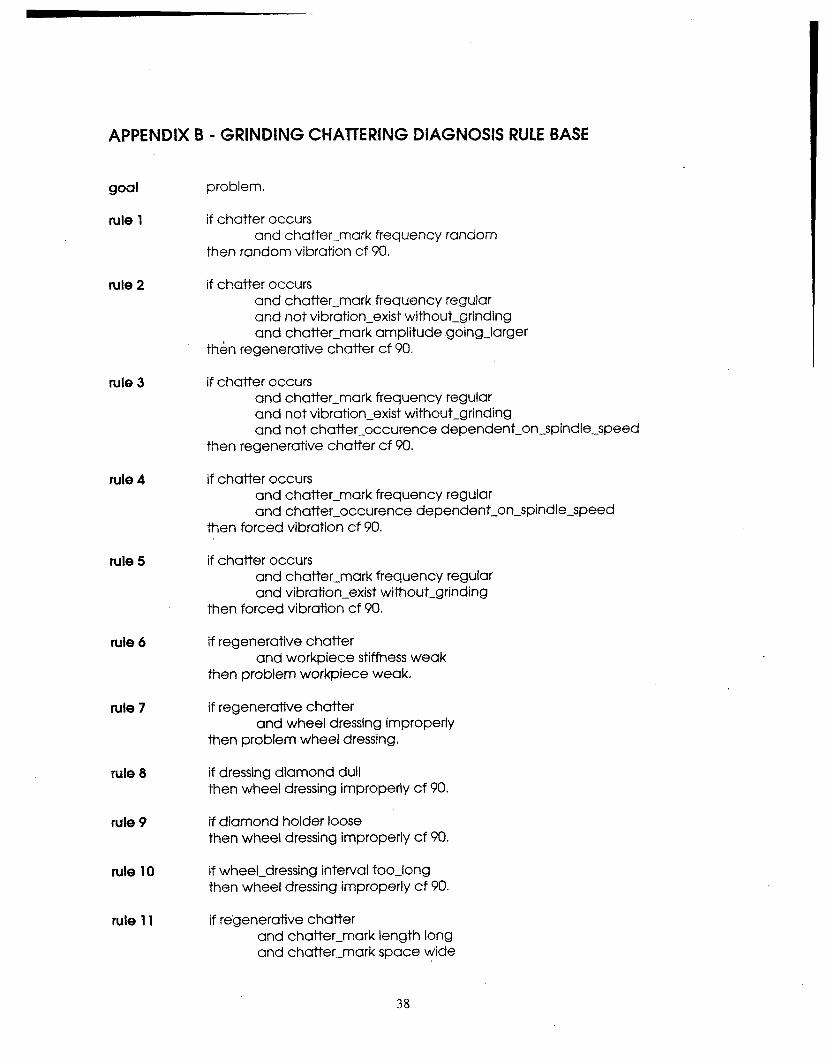
APPENDIX B - GRINDING 'CHATTERING DIAGNOSIS RULE BASE
goal problem.
rule 1 if chatter occurs and chatter-mark frequency random
then random vibration cf 90,
rule 2 if chatter occurs and chatter-mark frequency regular and not vibration-exist without-grinding and chatter-mark amplitude .going-larger
then regenerative chatter cf 90.
rule 3
rule 4
rule 5
rule 6
rule 7
rule 8
rule 9
rule 10
rule 11
if chatter occurs and chatter-mark frequency regular and not vibration-exist without-grinding and not chatter-occurence dependent-on-spindle-speed
then regenerative chatter cf 90.
if chatter occurs and chatter-mark frequency regular and chatter-occurence dependent-on-spindle-speed
then forced vibration cf 90.
if chatter occurs and chatter-mark frequency regular and vibration-exist without-grinding
then forced vibration cf 90.
if regenerative chatter and workpiece stiffness weak
then problem workpiece weak.
if regenerative chatter and wheel dressing improperly
then problem wheel dressing.
if dressing diamond dull then wheel dressing improperly cf 90.
if diamond holder loose then wheel dressing improperly cf 90.
if wheel-dressing interval too-long then wheel dressing improperly cf 90.
if re'generative chatter and chatter-mark length long and chatter-mark space wide

and workpiece discolored then problem wheel too-hard cf 90.
rule 12 if regenerative chatter and chatter-mark length long and chatter-mark space wide and wheel glazed-or-loaded
then problem wheel too-hard cf 90.
rule 13 if random vibration and thrust bearings work-bad
then problem thrust bearings.
rule 14 if thrust bearings out-of-round then thrust bearings work-bad.
rule 15 if thrust bearings worn-out then thrust bearings work-bad.
rule 16 if thrust bearings loose then thrust bearings work-bad.
rule 17 if random vibration and work-center-or-work-rest work-bad
then problem work-center-orwork-rest.
rule 18
ruie 19
rule 20
rule 21
rule 22
rub 23
rule 24
if not work-center-orwork-rest aligned then work-center-or-work-rest work-bad cf 90,
if work-center-or-workrest lubrication inadequate then work-center-or-work-rest work-bad cf 80.
if random vibration and not thrust bearings work-bad and not work-center-or-work-rest work-bad
then problem random-vibration outside-of-machine cf 60.
if forced vibration and thrust bearings work-bad
then problem thrust bearings.
if forced vibration and spindle belt with-metal-lacing
then problem spindle belt cf 90.
if forced vibration and chatter-mark length short and chatter-mark space close
then problem wheel-spindle bearings cf 80.
if forced vibration and chatter-mark length medium

rule 25
rule 26
rule 27
rule 28
rule 29
rule 30
rule 31
rule 32
rule 33
rule 34
rule 35
and chatter-mark space medium then problem wheel-spindle sprung-or-out-of-round cf 80.
if forced vibration and chatter-mark length medium and chatter-mark space wide
then problem wheel-spindle sprung-or-out-of-round cf 80.
if forced vibration and chatter-mark synchronous-with motor
then problem motor imbalance cf 90.
if forced vibration and chatter-mark synchronous-with electricity
then problem electricity imbalance cf 90.
if forced vibration and chatter-mark synchronous-with spindle and workpiece irregular
then problem workpiece imbalance cf 90.
if forced vibration and chatter-mark length short and chatter-mark space wide and flat-belt uneven.
then problem flat-belt uneven cf 90.
if forced vibration and chatter-mark length medium and chatter-mark space wide and flat-belt uneven
then problem flat-belt uneven cf 90.
if flat-belt thickness ununiform then flat-belt uneven.
if flat-belt width ununiform then flat-belt uneven.
if forced vibration and chatter-mark length short and chatter-mark space wide and not flat-belt uneven
then problem idlers loose~or~out~of~balance cf 80.
if forced vibration and chatter-mark length medium and chatter-mark space wide and not flat-belt uneven
then problem idlers loose~or~out~of~balance cf 80.
if forced vibration

rule 36
rule 37
ask
ask
ask
ask
ask
ask
ask
ask
ask
ask
and chatter-mark length long and chatter-mark pattern checkerboard
then problem wheel out-of-balance-or-round cf 80,
if forced vibration and chatter-mark synchronous-with wheel
then problem wheel out-of-balance-or-round cf 90.
if forced vibration and chatter-mark length long and chatter-mark space wide
then problem drive-gear back-lash cf 80.
chatter occurs menu- yes no prompt- 'chatter occurs ?I.
chatter-mark frequency menu- random regular prompt 'chatter-mark frequency ?'.
vibration-exist without-grinding menu- yes no prompt 'vibration-exist without-grinding ?',
chatte~mark amplitude menu- going-larger other prompt 'chatter-mark amplitude ?'.
chatter-occurence dependent-on-spindle-speed menu- yes no prompt 'chatter-occurence dependent-on-spindle-speed ? I .
workpiece stiffness menu- weak other prompt 'workpiece stiffness ?'.
dressing diamond menu- dull other prompt 'dressing diamond ?'.
diamond holder menu- loose other prompt- 'diamond holder ?'
wheel-dressing interval menu- too-long other prompt- 'wheeldressing interval ? I .
workpiece discolored menu- yes no prompt 'workpiece discolored ?'.
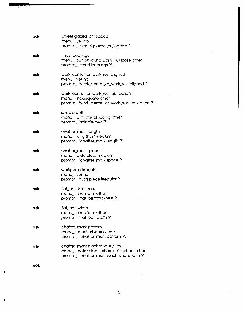
ask
ask
ask
ask
ask
ask
ask
ask
ask
ask
ask
ask
wheel glazed-or-loaded menu- yes no prompt- 'wheel glazed-or-loaded ?'.
thrust bearings menu- out-of-round worn-out loose other prompt- 'thrust bearings ?'.
work-center-or-work-rest aligned menu- yes no prompt 'work-center-or-work-rest aligned ?'.
work-center-orwork-rest lubrication menu- inadequate other prompt- 'work-center-or-work-rest lubrication ?'.
spindle belt menu- with-metal-lacing other prompt 'spindle belt ?'.
chatter-mark length menu- long short medium prompt 'chatter-mark length ?'.
chatter-mark space menu- wide close medium prompt 'chatter-mark space ?'.
workpiece irregular menu- yes no prompt 'workpiece irregular ?'.
flat-belt thickness menu- ununiform other prompt 'flat-belt thickness 7'.
flat-belt width menu- ununiform other prompt 'flat-belt width ?'.
chatter-mark pattern menu- checkerboard other prompt- 'chatter-mark pattern ?'
chatter-mark synchronous-with menu- motor electricity spindle wheel other prompt- 'chatter-mark synchronouswith ?'.
eof.