interface treatment in computational...
TRANSCRIPT
COMPDYN 20113rd ECCOMAS Thematic Conference on
Computational Methods in Structural Dynamics and Earthquake EngineeringM. Papadrakakis, M. Fragiadakis, V. Plevris (eds.)
Corfu, Greece, 25–28 May 2011
INTERFACE TREATMENT IN COMPUTATIONALFLUID-STRUCTURE INTERACTION
Thomas Kloppel, Alexander Popp and Wolfgang A. Wall
Institute for Computational Mechanics, Technische Universitat MunchenBoltzmannstr. 15, 85748 Garching b. Munchen, Germany
e-mail: kloeppel,popp,[email protected]
Keywords: Fluid-Structure Interaction, Non-Matching Meshes, Mortar Method, Dual LagrangeMultipliers, Finite Elements.
Abstract. Computational approaches for the simulation of fluid-structure interaction (FSI)problems have received much attention in recent years and their importance is still continuouslygrowing. The main reason for this is that FSI problems are of great relevance in all fields of en-gineering (civil, mechanical, aerospace, bio, etc.) as well as in the applied sciences. In order todevelop robust, reliable and efficient methods a number of challenges have to be met. This con-tribution focuses on the important question of how to treat the interface between solid and fluid.The topic is addressed by reviewing our novel, recently proposed method for dealing with non-matching grids in the context of moving grid FSI schemes. In contrast to available approachesin the literature, the proposed formulation is based on a mortar method with so-called dual La-grange multipliers and handles the additional complexity of coupling non-matching interfacemeshes at negligible computational cost. Owing to its generality, the resulting FSI frameworkdoes not introduce any restriction on the particular choice of finite element formulations neitherfor fluid, ALE nor structure. It allows for the application of state-of-the-art iterative solutionmethods to the resulting system matrices in a straightforward manner and shows an excellentperformance within monolithic FSI coupling algorithms.
1

Thomas Kloppel, Alexander Popp and Wolfgang A. Wall
1 INTRODUCTION
The numerical simulation of fluid-structure interaction (FSI) phenomena has long been afield of intensive research owing to its many applications in civil, mechanical, aerospace andbiomechanical engineering. Of particular interest is the interaction of incompressible flow withflexible structures undergoing finite deformations. We discuss here the most important featuresof our recently proposed dual mortar finite element method for dealing with non-matching in-terface meshes in the context of moving grid FSI schemes and monolithic coupling algorithms.The present contribution is thus a shortened version of our article [1] to which we refer for fulltechnical details, more profound discussion of the methods and further numerical examples.
Possible solution strategies for FSI problems range from weakly coupled partitioned overstrongly coupled partitioned to monolithic schemes. It could be shown that for some challeng-ing numerical problems such as collapsible tubes [2], thin-walled structures in the hemodynamicor respiratory system [3] or balloon-like problems of human red blood cells [4], monolithic cou-pling schemes outperform partitioned approaches or are even the only feasible schemes to solvethe problem at all. The issue of efficient and robust solvers for monolithic FSI scheme hasamong others been addressed in [5] where a novel algebraic multigrid preconditioner has beenproposed. In general and also in [5], monolithic schemes are derived based on the assumptionof a conforming interface discretization, i.e. fluid and structure share a common interface mesh.But only in very rare cases, this assumption will hold. Due to a manifold of reasons one gen-erally has to deal with non-matching grids at the fluid-structure interface. Most often differentresolution requirements in the different physical domains or quite simply the presence of com-plex interface geometries (e.g. in patient-specific biomechanics modeling) make the creation ofmatching fluid and structure meshes cumbersome or even impossible.
A possible remedy is provided by the mortar method, which has originally been introducedin the context of non-overlapping domain decomposition [6]. A characteristic feature of themortar method is the imposition of interface constraints in a variationally consistent mannerbased on Lagrange multipliers. This approach has seen a great thrust of research over the pastdecade. New fields of application such as finite deformation contact analysis [7, 8, 9, 10] havebeen established and the mathematical understanding concerning the choice of adequate discreteLagrange multiplier spaces has been deepened [11, 12, 13, 14].
Different other coupling methods for non-conforming interfaces in the framework of fluid-structure problems have been discussed for example in [15, 16, 17, 18, 19]. However, thosecontributions are limited to 2D analysis [16, 18] or only consider partitioned coupling schemes.The mortar method is referred to as a method with desirable mathematical and numerical prop-erties [15, 17], but it has not yet been used for FSI computations in a competitive manner. It isobvious that a straightforward application of the standard mortar method will raise numericalissues in the case of monolithic FSI schemes. The Lagrange multiplier degrees of freedom leadto a global system matrix with increased size and saddle point structure. Especially the latterlimits the practical use of this approach, since most iterative solvers rely on a matrix structurewith only non-zero diagonal entries. A condensation could remedy this problem but wouldnecessitate the inversion of a large matrix and is hence not feasible for practical purposes.
To overcome the numerical issues of the standard mortar method discussed above, we employa so-called dual mortar method [11, 12, 13, 14] with discrete Lagrange multipliers that areconstructed based on a biorthogonality relation with the primal shape functions at the fluid-structure interface. In contrast to standard mortar methods, the dual mortar approach allows foran elimination of the additional degrees of freedom by condensation at negligible computational
2
Thomas Kloppel, Alexander Popp and Wolfgang A. Wall
cost in the monolithic setting. This ensures that there are only non-zero diagonal entries in theglobal system matrix. We show that state-of-the-art iterative solvers for monolithic FSI systemswith matching interface meshes as proposed in [5] can be applied to the resulting global systemmatrices without any conceptual changes.
The remainder of this article is organized as follows: The next section briefly introduces themechanical problem and states the governing equations as well as the weak forms. In section 3the resulting monolithic system of equations after discretization and consistent linearization ispresented and we give some details on dual mortar coupling as well as on condensation of theLagrange multiplier degrees of freedom. Section 4 demonstrates the validity of the proposedapproach with a representative numerical example, and in section 5 we conclude the findings.
2 PROBLEM DESCRIPTION
FSI problems can formally be described as four field problems. To begin with, there aretwo physical fields, fluid and structure. Furthermore, to account for deformations of the fluiddomain, an arbitrary Lagrangian-Eulerian (ALE) approach is employed, constituting a third,non-physical mesh field later also called ALE field. Fluid and structure share a common FSIinterface Γ, but not necessarily a common finite element discretization of Γ. Therefore, couplingconditions are applied in a weak sense, introducing a field of Lagrange multipliers on Γ.
2.1 Fluid
The present FSI approach is not limited to a specific flow description. For the sake of brevitywe assume a fluid field governed by the instationary, incompressible Navier-Stokes equationsfor a Newtonian fluid on a deformable fluid domain ΩF. The unknown fluid domain deforma-tion dG is defined by a unique mapping ϕϕϕ given by
dG(x, t) = ϕϕϕ(dG
Γ ,x, t)
in ΩF× (0,T ), (1)
based on the mesh interface displacement dGΓ , that will later be related to the structure interface
displacement dSΓ. This mapping (1) is arbitrary and defines the domain velocity uG by
uG =∂ϕϕϕ∂ t
in ΩF× (0,T ), (2)
which has to match the fluid velocity uFΓ at the interface Γ, i.e.
uFΓ = uG
Γ in Γ× (0,T ). (3)
Equation (2) allows for the definition of the ALE convective velocity c = uF− uG, repre-senting the fluid velocity relative to the arbitrarily moving fluid domain. The Navier-Stokesequations of the fluid field hence read
∂uF
∂ t+ c ·∇∇∇uF−2ν∇∇∇ ·εεε(uF)+∇pF = bF, (4)
∇∇∇ ·uF = 0, (5)
both valid in ΩF× (0,T ), where fluid velocity uF and kinematic fluid pressure pF are unknown.In the momentum equation (4), bF denotes a body force, εεε(uF) = 1
2
(∇∇∇uF +(∇∇∇uF)T)
the strainrate tensor of the Newtonian fluid and ν its kinematic viscosity. Equation (5) states the fluid’s
3
Thomas Kloppel, Alexander Popp and Wolfgang A. Wall
incompressibility deduced from the conservation of mass and a constant density ρF. The fluidsystem is completed by the usual Dirichlet and Neumann boundary conditions and an initialdivergence-free velocity field uF
0 .The weak form of the incompressible Navier-Stokes equations (4) and (5) is obtained by
testing these equations with test functions δuF for velocity and δ pF for pressure and subsequentintegration by parts
0 =(
δuF,∂uF
∂ t
)
ΩF+
(δuF,c ·∇∇∇uF)
ΩF +(∇∇∇δuF,2νεεε(uF)
)ΩF −
(∇∇∇ ·δuF, pF)
ΩF
− (δuF,bF)
ΩF −(δ pF,∇∇∇ ·uF)
ΩF +(δuF, hF)
ΓFN+δW F
Γ , (6)
where ΓFN denotes the Neumann boundary and δW F
Γ denotes a contribution of the FSI interfacethat will be deduced in section 2.3.
2.2 Structure
In this work we assume a structure field governed by the nonlinear elastodynamics equation
ρS d2dS
dt2 = ∇∇∇ ·(FS)+ρSbS in ΩS× (0,T ), (7)
which states an equilibrium between the forces of inertia, internal forces and an external bodyforce bS in the undeformed structural configuration ΩS. Given the structural density ρS de-fined per unit undeformed volume, equation (7) has to be solved for the unknown structuraldisplacements dS. The internal forces are expressed in terms of the second Piola-Kirchhoffstress tensor S and the deformation gradient F.
Different constitutive relations can be employed in this context, but for the sake of simplicitya hyperelastic material behavior with strain energy function Ψ is considered in the remainderof this paper. The second Piola-Kirchhoff stress tensor S is thus defined as
S = 2∂Ψ∂C
, (8)
where the right Cauchy-Green tensor C = FTF has been introduced. Dirichlet and Neumannboundary conditions as well as the usual initial boundary conditions, given initial displacementsand velocities dS
0 and dS0 , respectively, have to be additionally satisfied.
Testing (7) with the virtual displacements δdS and integration by parts yield the weak form
0 =(
δdS,ρS d2dS
dt2
)
ΩS+
(∇∇∇δdS,FS
)ΩS −
(δdS,ρSbS)
ΩS −(δdS, hS)
ΓSN+δW S
Γ , (9)
where ΓSN denotes the Neumann boundary. The influence of the interface on the structure field
is accounted for by δW SΓ , which will be discussed in the following subsection.
2.3 Fluid-Structure Interface
Coupling of the different fields is realized by enforcing kinematic and dynamic constraintsat the fluid-structure interface Γ. Usually, the no-slip boundary condition
∂dSΓ
∂ t= uF
Γ in Γ× (0,T ) (10)
4

Thomas Kloppel, Alexander Popp and Wolfgang A. Wall
is applied, which prohibits both a mass flow across and a relative tangential movement of fluidand structure at the fluid-structure interface. In combination with (3) this condition (10) isequivalent to
dSΓ = dG
Γ in Γ× (0,T ), (11)
stating that structural deformation and fluid movement (represented by the ALE based fluiddomain deformation dG
Γ ) must match on Γ. In addition, equilibrium of forces requires thesurface tractions of fluid and structure to be equal, yielding
hSΓ =−hF
Γ in Γ× (0,T ). (12)
In preparation of the mortar finite element discretization to follow, the method of weightedresiduals is applied to the interface conditions. By introducing the Lagrange multiplier field λλλand corresponding test functions δλλλ on the fluid-structure interface Γ, we obtain the weak form
(δλλλ ,dS
Γ−dGΓ)
Γ = 0. (13)
This adds an integral version of the continuity constraint (11) to the general problem definition.Furthermore, the unknown surface tractions introduced in (12) have to be imposed in a weaksense on the respective physical field, yielding the missing coupling terms in fluid weak form(6) and structure weak form (9)
δW FΓ =
(hF
Γ,δuFΓ)
Γ , (14)
δW SΓ =
(hS
Γ,δdSΓ)
Γ . (15)
Identifying the Lagrange multiplier field λλλ with the unknown surface traction hSΓ =−hF
Γ, thesecoupling terms can be expressed as
δW FΓ =−(
λλλ ,δuFΓ)
Γ , (16)
δW SΓ =
(λλλ ,δdS
Γ)
Γ . (17)
Thus, fluid-structure coupling is established in a weak sense, which formally leads to a fourfield FSI system.
3 DISCRETIZATION AND SOLUTION ALGORITHM
3.1 The monolithic FSI system
To derive the monolithic FSI system of equations, the governing equations stated above arediscretized in space and time and the resulting non-linear equations are linearized consistentlyin order to apply a Newton-Raphson algorithm. Note that the presented algorithm is not limitedto a particular choice of these discretizations. In general, we use finite element discretizationsfor fluid, ALE and structure fields and implicit time integration schemes.
5
Thomas Kloppel, Alexander Popp and Wolfgang A. Wall
The final linear system of equation for timestep n+1 and iteration step i then emerges as
SII SIΓSΓI SΓΓ CT
SFII FIΓ + ∆t
2 FGIΓ FG
IIFΓI FΓΓ + ∆t
2 FGΓΓ FG
ΓI −CTF
0 ∆t2 AIΓ AII
CS −∆t2 CF
∆∆∆dS,n+1I,i
∆∆∆dS,n+1Γ,i
∆∆∆uF,n+1I,i
∆∆∆uF,n+1Γ,i
∆∆∆dG,n+1I,i
λλλ n+1i
=
−
fS,n+1I,i
fS,n+1Γ,i
fF,n+1I,i
fF,n+1Γ,i
00
−δi0∆t
00
FGIΓuF,n
ΓFG
ΓΓuF,nΓ
AIΓuF,nΓ
CFuF,nΓ
, (18)
where δi0 denotes the Kronecker delta. In equation (18) the vector of unknowns and the right-hand side are split in quantities defined on the FSI interface denoted by ·Γ and in the interiorfield denoted by · I. This split then propagates to the matrix block structure. The block structureof the structure stiffness matrix S is defined as Sαβ = ∂ fS
α/∂dSβ , α,β ∈ I,Γ, where fS denotes
the residual vector and dS the vector of discretized nodal displacements. To shorten the notationfor the fluid part, we have merged the pressure degrees of freedom into the vector of fluidinterior unknowns. Fluid entries are then defined as Fαβ = ∂ fF
α/∂uFβ and shape derivatives as
FGαβ = ∂ fF
α/∂dGβ ,α,β ∈ I,Γ. Here, fF denotes the fluid residual, uF the vector of discretized
fluid unknowns and dG the vector of fluid grid displacements. The ALE system matrix A is splitaccordingly into blocks AIΓ and AII.
The system is completed by coupling matrices CS and CF. The last row of (18) weaklyimposes the continuity constraint (11) and thus represents the discrete version of (13). Thecontributions of the vector of discretized Lagrange multiplier values λλλ , i.e. −CFλλλ and CSλλλ ,account for the additional surface tractions on the fluid and structure field, respectively, whichresult from the coupling at the FSI interface and correspond to (16) and (17).
3.2 Dual mortar coupling
Non-conforming finite element discretization brings about that fluid and structure surfacesat the FSI interface Γ do not match any more, as it is the case when using node-matchinginterface meshes. For making the following derivations more general, we define so-called slaveand master sides Γsl and Γma, introduce the displacement fields dsl
Γ and dmaΓ and derive the dual
mortar method as an abstract coupling strategy for two non-conforming meshes. The generalform of slave and master displacement interpolation then reads
dslΓ =
nsl
∑k=1
Nslk dsl
k , dmaΓ =
nma
∑l=1
Nmal dma
l , (19)
where shape functions Nslk , Nma
l are obtained based on their trace space relationship with theunderlying discretizations of the domains ‘behind‘ the mortar interface (in this context fluid
6
Thomas Kloppel, Alexander Popp and Wolfgang A. Wall
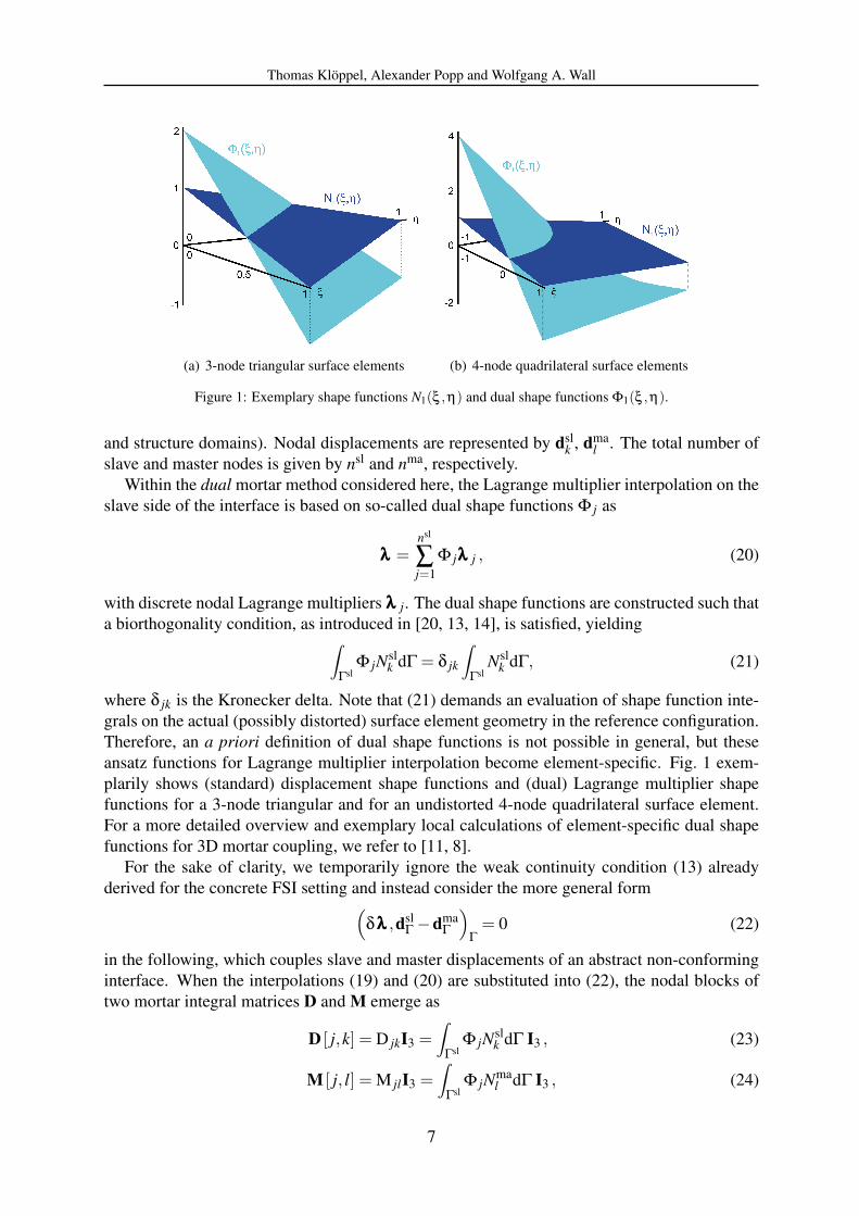
(a) 3-node triangular surface elements (b) 4-node quadrilateral surface elements
Figure 1: Exemplary shape functions N1(ξ ,η) and dual shape functions Φ1(ξ ,η).
and structure domains). Nodal displacements are represented by dslk , dma
l . The total number ofslave and master nodes is given by nsl and nma, respectively.
Within the dual mortar method considered here, the Lagrange multiplier interpolation on theslave side of the interface is based on so-called dual shape functions Φ j as
λλλ =nsl
∑j=1
Φ jλλλ j , (20)
with discrete nodal Lagrange multipliers λλλ j. The dual shape functions are constructed such thata biorthogonality condition, as introduced in [20, 13, 14], is satisfied, yielding
∫
ΓslΦ jNsl
k dΓ = δ jk
∫
ΓslNsl
k dΓ, (21)
where δ jk is the Kronecker delta. Note that (21) demands an evaluation of shape function inte-grals on the actual (possibly distorted) surface element geometry in the reference configuration.Therefore, an a priori definition of dual shape functions is not possible in general, but theseansatz functions for Lagrange multiplier interpolation become element-specific. Fig. 1 exem-plarily shows (standard) displacement shape functions and (dual) Lagrange multiplier shapefunctions for a 3-node triangular and for an undistorted 4-node quadrilateral surface element.For a more detailed overview and exemplary local calculations of element-specific dual shapefunctions for 3D mortar coupling, we refer to [11, 8].
For the sake of clarity, we temporarily ignore the weak continuity condition (13) alreadyderived for the concrete FSI setting and instead consider the more general form
(δλλλ ,dsl
Γ −dmaΓ
)Γ
= 0 (22)
in the following, which couples slave and master displacements of an abstract non-conforminginterface. When the interpolations (19) and (20) are substituted into (22), the nodal blocks oftwo mortar integral matrices D and M emerge as
D [ j,k] = D jkI3 =∫
ΓslΦ jNsl
k dΓ I3 , (23)
M [ j, l] = M jlI3 =∫
ΓslΦ jNma
l dΓ I3 , (24)
7
Thomas Kloppel, Alexander Popp and Wolfgang A. Wall
with the 3×3 identity matrix I3. Herein, D is a square 3nsl×3nsl matrix, whereas the definitionof M generally yields a rectangular matrix of dimensions 3nsl× 3nma. Inserting the biorthog-onality relation (21) into (23) allows for the advantageous simplification of D to become adiagonal matrix with nodal blocks
D [ j,k] = D jkI3 = δ jk
∫
ΓslNsl
k dΓ I3 . (25)
Finally, the discrete form of the general weak continuity condition (22) reads
DdslΓ −Mdma
Γ = 0, (26)
which naturally defines a discrete projection from master to slave displacements as
dslΓ = D−1Mdma
Γ . (27)
Equation (27) illustrates one major advantage of the dual mortar approach as compared withstandard mortar schemes. The discrete projection operator P = D−1M at a non-conforminginterface can be applied locally based on the trivial inversion of the diagonal matrix D. Thus,evaluating (27) does not require the solution of a possibly large linear system of equations.This evades the high computational cost associated with standard mortar coupling of two non-conforming grids. Note that depending on the choice of structure or fluid as slave side for themortar approach, the discrete coupling matrices CS and CF in (18) can be identified with themortar matrices D and M.
3.3 Condensed linear system
The four-field linear system in (18) is in general very hard to solve numerically with paralleliterative linear solvers, because of the saddle point type structure of the problem. Since largermodel sizes necessitate this type of solvers, the linear system is transformed into the sameblock-structure as the standard monolithic FSI system for conforming discretizations shown in[5]. The transformation is based on condensation of the Lagrange multipliers, which is onlypossible due to the dual mortar approach discussed in section 3.2.
Of course both choices for master and slave side of the mortar coupling are possible andresult in viable algorithms as has been shown in great detail in [1]. For the sake of brevity, inthis contribution only one possibility is discussed: we assume that the structure side of the FSIinterface Γ serves as slave side for the mortar coupling. Thus the coupling matrices in (18) canbe identified as CF = M and CS = D.
The second row of (18) is solved for the Lagrange multipliers λλλ n+1i , involving a trivial in-
version of the diagonal matrix D. The result can then be substituted into the fourth row of (18),so that the Lagrange multipliers are fully eliminated from the system. A further reduction canbe obtained by a transformation of the last row of (18), which allows to express the structureinterface displacement updates ∆∆∆dS,n+1
Γ,i in terms of fluid interface velocity updates ∆∆∆uF,n+1Γ,i .
8

Thomas Kloppel, Alexander Popp and Wolfgang A. Wall
Subsequent substitution and reordering yield the final reduced system of equations
SII∆t2 SIΓP
PTSΓI∆t2 PTSΓIP+FΓΓ + ∆t
2 FGΓΓ FΓI FG
ΓIFIΓ + ∆t
2 FGIΓ FII FG
II∆t2 AIΓ 0 AII
∆∆∆dS,n+1I,i
∆∆∆uF,n+1Γ,i
∆∆∆uF,n+1I,i
∆∆∆dG,n+1I,i
=
fS,n+1I,i
fF,n+1Γ,i +PTfS,n+1
Γ,i
fF,n+1I,i
0
+δi0 ∆t
SIΓPuF,nΓ(
PTSΓΓP+FGΓΓ
)uF,n
ΓFG
IΓuF,nΓ
AIΓuF,nΓ
. (28)
4 EXAMPLE
To demonstrate the efficiency of the proposed method, different discretizations of the samefluid filled circular pipe with traveling pressure wave are considered. The example is motivatedby [5, 21]. The tube is 0.1m long, has an inner radius of 0.01m and an outer radius of 0.011m.The structure is described with a Neo-Hookean material law with Young’s modulus E = 105 Pa,Poisson’s ratio ν = 0.3 and a density of ρS = 1,200kg/m3. The Newtonian fluid inside thetube has a dynamic viscosity of µ = 0.003Pas and a density of ρF = 1,000kg/m3. The inflowsurface is loaded with a surface traction of 1,000Pa for 0.003s. For the computation a timestepsize of ∆t = 1.0×10⁻⁴ s is used and 250 timesteps are performed. The fluid is discretizedwith stabilized hexahedral finite elements, the structure with hexahedral solid shell elementsproposed in [22].
We concentrate on four fluid discretizations denoted by A, B, C and D with different meshsizes, which range from 2,080 to 130,560 elements. For all fluid mesh sizes corresponding con-forming and non-conforming structure discretizations are considered. In the non-conformingversions the structure mesh is rotated such that the meshes overlap in circumferential direc-tion by approximately a third of an element length, see Fig. 2(a). Furthermore, it containstwo elements less than the fluid discretization across the length of the tube. The coarsest non-conforming model can be seen in Fig. 2.
Computations are performed in parallel on up to 12 processors. In order to study efficiencyand scalability of the proposed approach, we distinguish not only between conforming andnon-conforming (NC), but consider two solution methods for the conforming case: with mortar
(a) front view (b) side view
Figure 2: Coarse, non-conforming mesh A for pressure wave example.
9
Thomas Kloppel, Alexander Popp and Wolfgang A. Wall
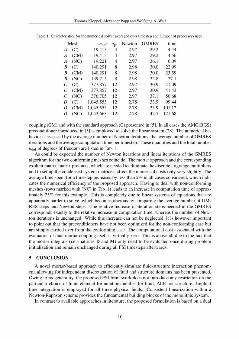
Table 1: Characteristics for the numerical solver averaged over timestep and number of processors used.
Mesh ndof npr Newton GMRES timeA (C) 19,413 4 2.97 29.2 4.44A (CM) 19,413 4 2.97 29.2 4.56A (NC) 19,221 4 2.97 36.1 6.09B (C) 140,291 8 2.98 30.0 22.99B (CM) 140,291 8 2.98 30.0 23.59B (NC) 139,715 8 2.98 32.8 27.1C (C) 377,857 12 2.97 30.9 41.09C (CM) 377,857 12 2.97 30.9 41.43C (NC) 376,705 12 2.97 37.1 50.68D (C) 1,045,553 12 2.78 33.9 99.44D (CM) 1,045,553 12 2.78 33.9 101.12D (NC) 1,043,663 12 2.78 42.7 121.68
coupling (CM) and with the standard approach (C) presented in [5]. In all cases the AMG(BGS)preconditioner introduced in [5] is employed to solve the linear system (28). The numerical be-havior is assessed by the average number of Newton iterations, the average number of GMRESiterations and the average computation time per timestep. These quantities and the total numberndof of degrees of freedom are listed in Tab. 1.
As could be expected the number of Newton iterations and linear iterations of the GMRESalgorithm for the two conforming meshes coincide. The mortar approach and the correspondingexplicit matrix-matrix products, which are needed to eliminate the discrete Lagrange multipliersand to set up the condensed system matrices, affect the numerical costs only very slightly. Theaverage time spent for a timestep increases by less than 2% in all cases considered, which indi-cates the numerical efficiency of the proposed approach. Having to deal with non-conformingmeshes (rows marked with ’NC’ in Tab. 1) leads to an increase in computation time of approx-imately 25% for this example. This is completely due to linear systems of equations that areapparently harder to solve, which becomes obvious by comparing the average number of GM-RES steps and Newton steps. The relative increase of iteration steps needed in the GMREScorresponds exactly to the relative increase in computation time, whereas the number of New-ton iterations is unchanged. While this increase can not be neglected, it is however importantto point out that the preconditioners have not been optimized for the non-conforming case butare simply carried over from the conforming case. The computational cost associated with theevaluation of dual mortar coupling itself is virtually zero. This is above all due to the fact thatthe mortar integrals (i.e. matrices D and M) only need to be evaluated once during probleminitialization and remain unchanged during all FSI timesteps afterwards.
5 CONCLUSION
A novel mortar-based approach to efficiently simulate fluid-structure interaction phenom-ena allowing for independent discretization of fluid and structure domains has been presented.Owing to its generality, the proposed FSI framework does not introduce any restriction on theparticular choice of finite element formulations neither for fluid, ALE nor structure. Implicittime integration is employed for all three physical fields. Consistent linearization within aNewton-Raphson scheme provides the fundamental building blocks of the monolithic system.
In contrast to available approaches in literature, the proposed formulation is based on a dual
10

Thomas Kloppel, Alexander Popp and Wolfgang A. Wall
mortar method and handles the additional complexity of non-matching interface meshes at neg-ligible computational cost. The complete four-field monolithic system initially has a saddlepoint type structure, but is then transformed into a three-field system by condensation of theLagrange multiplier degrees of freedom. The transformation requires the inversion of one ofthe coupling matrices, which is trivial due to its diagonal shape. This diagonality is a key fea-ture of the dual mortar approach as opposed to standard mortar coupling schemes. Because ofthe transformation the application of state-of-the-art iterative solution methods to the resultingsystem matrices is straightforward.
In particular, block-specific preconditioners tailored for conforming monolithic FSI showexcellent performance also in the non-conforming case, which is demonstrated with the well-known pressure wave example. It also shows that computational cost associated with the evalu-ation of dual mortar coupling itself and with the additional matrix-matrix multiplication neces-sary in some sub-blocks of the monolithic system is very low.
REFERENCES
[1] T. Kloppel, A. Popp, U. Kuttler, W.A. Wall, Fluid-structure interaction for non-conforminginterfaces based on a dual mortar formulation. Computer Methods in Applied Mechanicsand Engineering, submitted, 2010.
[2] M. Heil, An efficient solver for the fully coupled solution of large-displacement fluid–structure interaction problems. Computer Methods in Applied Mechanics and Engineer-ing, 193, 1–23, 2004.
[3] U. Kuttler, M. Gee, Ch. Forster, A. Comerford, W.A. Wall, Coupling strategies forbiomedical fluid-structure interaction problems. International Journal for NumericalMethods in Biomedical Engineering, 26, 305–321, 2010.
[4] T. Kloppel, W.A. Wall, A novel two-layer, coupled finite element approach for the non-linear elastic and viscoelastic behavior of human erythrocytes. Biomech. Model. Mechan.,DOI: 10.1007/s10237-010-0246-2, 2010.
[5] M. W. Gee, U. Kuttler, W. A. Wall, Truly monolithic algebraic multigrid for fluid-structureinteraction. Int. J. Numer. Meth. Engng., 85(8), 987–1016, 2011.
[6] C. Bernardi, Y. Maday, A.T. Patera, A new nonconforming approach to domain decompo-sition: the mortar element method. H. Brezis, J.L. Lions eds. Nonlinear partial differentialequations and their applications, Pitman/Wiley: London/New York, 1994.
[7] A. Popp, M.W. Gee, W.A. Wall, A finite deformation mortar contact formulation using aprimal-dual active set strategy. International Journal for Numerical Methods in Engineer-ing, 79, 1354–1391, 2009.
[8] A. Popp, M. Gitterle, M.W. Gee, W.A. Wall, A dual mortar approach for 3D finite defor-mation contact with consistent linearization. International Journal for Numerical Methodsin Engineering, 83, 1428–1465, 2010.
[9] M.A. Puso, T.A. Laursen, A mortar segment-to-segment contact method for large defor-mation solid mechanics. Computer Methods in Applied Mechanics and Engineering, 193,601–629, 2004.
11

Thomas Kloppel, Alexander Popp and Wolfgang A. Wall
[10] M.A. Puso, T.A. Laursen, A mortar segment-to-segment frictional contact method forlarge deformations. Computer Methods in Applied Mechanics and Engineering, 193,4891–4913, 2004.
[11] B. Flemisch, B.I. Wohlmuth, Stable lagrange multipliers for quadrilateral meshes ofcurved interfaces in 3D. Computer Methods in Applied Mechanics and Engineering, 196,1589–1602, 2007.
[12] M.A. Puso, A 3D mortar method for solid mechanics. International Journal for NumericalMethods in Engineering, 59, 315–336, 2004.
[13] B.I. Wohlmuth, A mortar finite element method using dual spaces for the Lagrange multi-plier. SIAM Journal on Numerical Analysis, 38, 989–1012, 2000.
[14] B.I. Wohlmuth, Discretization methods and iterative solvers based on domain decompo-sition. Springer-Verlag Berlin Heidelberg, 2001.
[15] A. de Boer, A.H. van Zuijlen, H. Bijl, Review of coupling methods for non-matchingmeshes. Computer Methods in Applied Mechanics and Engineering, 196, 1515–1525,January 2007.
[16] W. Dettmer, D. Peric, A computational framework for fluid-structure interaction: Finiteelement formulation and applications. Computer Methods in Applied Mechanics and En-gineering, 195, 5754–5779, 2006.
[17] C. Farhat, M. Lesoinne, P. Le Tallec, Load and motion transfer algorithms forfluid/structure interaction problems with non-matching discrete interfaces: Momentumand energy conservation, optimal discretization and application to aeroelasticity. Com-puter Methods in Applied Mechanics and Engineering, 157, 95–114, 1998.
[18] H.-G. Kim, A new coupling strategy for fluid-solid interaction problems by using theinterface element method. International Journal for Numerical Methods in Engineering,81, 403–428, 2010.
[19] M.R. Ross, M.A. Sprague, C.A. Felippa, K.C. Park, Treatment of acoustic fluid-structureinteraction by localized lagrange multipliers and comparison to alternative interface-coupling methods. Computer Methods in Applied Mechanics and Engineering, 198, 986–1005, 2009.
[20] S. Hueber, B.I. Wohlmuth, A primal-dual active set strategy for non-linear multibody con-tact problems. Computer Methods in Applied Mechanics and Engineering, 194, 3147–3166, 2005.
[21] J.F. Gerbeau, M. Vidrascu, A quasi-Newton algorithm based on a reduced model for fluid-structure interaction problems in blood flow. Mathematical Modelling and NumericalAnalysis, 37(4), 631–647, 2003.
[22] L. Vu-Quoc, X.G. Tan, Optimal solid shells for non-linear analyses of multilayer compos-ites. i. statics. Computer Methods in Applied Mechanics and Engineering, 192, 975–1016,2003.
12