seismic shear demand on rc structural...
TRANSCRIPT
COMPDYN 2011
III ECCOMAS Thematic Conference on
Computational Methods in Structural Dynamics and Earthquake Engineering M. Papadrakakis, M. Fragiadakis, V. Plevris (eds.)
Corfu, Greece, 25–28 May 2011
SEISMIC SHEAR DEMAND ON RC STRUCTURAL WALLS:
REVIEW AND BIBLIOGRAPHY
Avigdor Rutenberg
Technion – Israel Institute of Technology
Haifa 32000 Israel
Keywords: Earthquake engineering, structural walls & wall frames, higher modes, shear de-mand.
Abstract: Effect of higher vibration modes on the seismic shear demand of reinforced con-crete cantilever walls has been studied since the 1970’s. The shear amplification becomes
more important with increasing fundamental period (tall buildings) and increasing ductility
demand (R or q factors). Yet, studying the relevant recommendations of structural engineer-
ing researchers and provisions of various seismic codes reveals that there is no consensus re-
garding the extent of shear amplification and of the inter-wall distribution of shear demand in
structural systems comprising walls of different lengths.
Paper presents the available formulas for predicting shear amplification in ductile walls
and dual systems (wall-frames), as well as techniques for estimating the shear distribution
among interconnected unequal walls. The consideration, or absence, of these effects by lead-
ing seismic code provisions is also noted.
One effect that impacts the shear amplification is shear cracking mainly in the plastic hinge
zone of the wall near the base resulting in very low effective shear stiffness. Also, deliberately
allowing development of plastic hinging along the wall height (contrary to standard code re-
quirements) has been suggested. These appear to lead to appreciably lower shear amplifica-tion than previously predicted.
Finally, an extensive bibliography (circa 100 refs.) is provided.
Avigdor Rutenberg
2
1 INTRODUCTION
This paper reviews the literature on the seismic shear demand on RC cantilever walls. It is
mainly concerned with shear amplification due to higher vibration modes, and it also reports on the post-yield redistribution of shear demand among the walls in systems comprising sev-
eral walls of different lengths. Amplification of wall shear due to higher vibration modes in the elastic range was not widely recognized by structural engineers until the early 1970’s, alt-
hough it was, or at least should have been, a known phenomenon to users of modal analysis for the seismic design of RC walls in tall buildings. However, the larger shear magnification
in yielding flexural walls due to higher modes was first observed by New Zealand consulting
engineers, which led to the 1975 pioneering paper by Blakeley et al [9]. The problem was also
studied by researchers at the Portland Cement Association, and these resulted in a series of
PCA reports [21, 23] and papers [22, 24] by Derecho and coworkers. The amplification tables
proposed by Blakeley et al [9], the charts by Derecho et al [23], as well as later amplification
expressions or charts (e.g. [29, 36, 37, 79, 81, 88, 95, 96]; and for wall-frames: [4, 38, 39, 43,
56, 81, 89]) were mainly based on results of nonlinear response history parametric studies us-
ing suites of accelerograms. Obviously, the result depended on the choice of these suites.
Theoretically oriented general formulation for the shear amplification was given by Keintzel
[27, 50, 51]. Extensions were proposed by Priestley [79, 80, 81], and for wall-frames by Sul-
livan et al [100]. Very recently Fischinger et al [32] presented a correction to Keintzel’s for-
mula, and Pennucci et al [76] modification thereof.
Shear amplification becomes more important with increasing fundamental period (tall buildings) and increasing ductility demand (R or q factors). Yet, studying the relevant rec-
ommendations of structural engineering researchers and provisions of various seismic codes reveals that there is no consensus regarding the extent of shear amplification, its height-wise
variations, and the inter-wall shear demand distribution when the structural system consists of interconnected wall of different lengths.
This paper is concerned only with shear demand amplification on structural walls due to the effects of higher modes, but not with moment magnification along the height, which de-
rives from the same source. Issues related to the shear capacity and post-yield shear flexure
interaction are beyond the scope of the present study.
The phenomenon is described first, then available procedures to predict the amplification
are presented, and relevant code provisions are briefly discussed. Shear amplification in dual
or wall-frame structures is also included in the review, and post-elastic shear demand redistri-
bution among the walls in systems with walls of unequal length is considered. The paper clos-
es with a discussion including some unresolved issues.
The structural engineering communities in North America and in many other countries have been slow in recognizing the need to amplify shear demand, if at all. The objection of
many researchers and engineers to the rather large amplification in the nonlinear range ob-
tained from numerical simulations may perhaps explain the plethora of publications as essays
in persuasion, manifested by the quite long bibliography on this rather limited problem at the
end of this paper.
2 THE SHEAR AMPLIFICATION PHENOMENON
In the linear range the amplification of shear demand in flexural walls due to higher vibra-
tion modes has been routinely accounted for by means of response spectrum analysis. This
matter is well covered in standard textbooks. Figure 1, taken from Chopra [18], shows the base shear Vb normalized by the total weight W in buildings analyzed by the modal response
spectrum technique for a typical design spectrum. It can be seen that for a flexural cantilever

Avigdor Rutenberg
3
wall (ρ = 0 , ρ = beam to column stiffness ratio) the base shear increases appreciably with in-creasing natural period due the effect of higher modes compared with the design spectrum.
This fact explains the requirement in many seismic codes (e.g. [16]) to permit use of the
equivalent lateral force procedure only for buildings with T1 < max (4Τc, 2.0 sec), Tc = corner
period to the velocity related spectral acceleration region. As can be seen, in frame structures
(ρ >> 0) the shear amplification due to higher modes is appreciably much smaller. The main reasons for this difference are: (1) the combined effective mass of the higher modes in flexur-
al walls is circa 35% of the total mass vs. circa 25% in frames ; (2) the period ratios of the 1st
mode to the higher ones is much larger for flexural walls (e.g. 1st/2nd ≈ 6 vs. ≈ 3 for ideal
frames). Hence, when T1 of a flexural wall is in the velocity spectral region, the higher modes
- the spectral accelerations of which are usually located at the high acceleration plateau – have
a larger effect on the shear than in frames. This effect is even more pronounced when T1 is
longer so that Sa (T2) and even Sa (T3) are in the velocity spectral region. Indeed, the main ef-
fect of the higher modes is due to the 2nd mode (e.g. [50, 66, 68]) and, to a much lesser extent,
to the 3rd. mode. Evidently, the shape of the spectrum also strongly affects the extent of am-
plification. The reader is referred to Chopra [18] and Humar & Mahgoub [41] for detailed
consideration of the phenomenon. The way seismic codes consider this effect is described
subsequently.
Fig. 1: Normalized base shear Vb/W for 3 values of ρ; for walls ρ = 0 (Chopra 2001).
As already noted, the shear amplification due to higher modes in the nonlinear range has
attracted considerable interest since the Blakeley et al 1975 paper [9]. They showed, by means of nonlinear response history analysis (NLRHA), that shear demand increases with natural
period and falling damping ratio. Similar results were obtained by Derecho et al [21], Keintzel
[49] and Kabeyasawa [43, 44, 45], who also demonstrated that shear demand increases with ductility demand. The following explanation for the latter effect was given by Paulay &
Priestley [75]. At some instants during the response the higher modes combine with the 1st
Avigdor Rutenberg
4
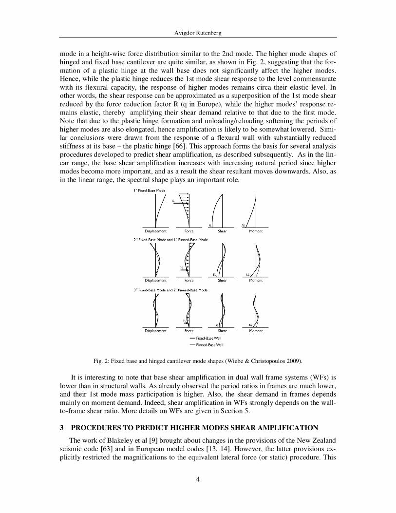
mode in a height-wise force distribution similar to the 2nd mode. The higher mode shapes of hinged and fixed base cantilever are quite similar, as shown in Fig. 2, suggesting that the for-
mation of a plastic hinge at the wall base does not significantly affect the higher modes. Hence, while the plastic hinge reduces the 1st mode shear response to the level commensurate
with its flexural capacity, the response of higher modes remains circa their elastic level. In other words, the shear response can be approximated as a superposition of the 1st mode shear
reduced by the force reduction factor R (q in Europe), while the higher modes’ response re-
mains elastic, thereby amplifying their shear demand relative to that due to the first mode.
Note that due to the plastic hinge formation and unloading/reloading softening the periods of
higher modes are also elongated, hence amplification is likely to be somewhat lowered. Simi-
lar conclusions were drawn from the response of a flexural wall with substantially reduced
stiffness at its base – the plastic hinge [66]. This approach forms the basis for several analysis
procedures developed to predict shear amplification, as described subsequently. As in the lin-
ear range, the base shear amplification increases with increasing natural period since higher
modes become more important, and as a result the shear resultant moves downwards. Also, as
in the linear range, the spectral shape plays an important role.
Fig. 2: Fixed base and hinged cantilever mode shapes (Wiebe & Christopoulos 2009).
It is interesting to note that base shear amplification in dual wall frame systems (WFs) is
lower than in structural walls. As already observed the period ratios in frames are much lower, and their 1st mode mass participation is higher. Also, the shear demand in frames depends
mainly on moment demand. Indeed, shear amplification in WFs strongly depends on the wall-to-frame shear ratio. More details on WFs are given in Section 5.
3 PROCEDURES TO PREDICT HIGHER MODES SHEAR AMPLIFICATION
The work of Blakeley et al [9] brought about changes in the provisions of the New Zealand
seismic code [63] and in European model codes [13, 14]. However, the latter provisions ex-
plicitly restricted the magnifications to the equivalent lateral force (or static) procedure. This

Avigdor Rutenberg
5
turned out to be unfortunate since the corollary was that amplification was understood not to
be required when using modal analysis (as, e.g. the Israeli seismic code [97] without Amend-
ment 3, is interpreted). It also led engineers to overlook the fact that a major part of the shear
amplification due to higher modes takes place in the post-elastic range. This attitude still per-
sists also in the National Building Code of Canada NBCC-2005 [61], which only accounts for
linear multi-mode shear amplification. However, the present Canadian Concrete code CSA-
A23.3-04 [19] requires considering nonlinear shear amplification, yet gives no guidance to that effect
(see also [10]), although the commentary to the 1994 version of that code suggested adopting the New
Zealand shear amplification formulas. Note that in the provisions and the proposals described subse-
quently it was tacitly assumed that the plastic hinge could form only at the wall base, and that the pre-
scribed moment envelope took care of that.
The amplified shear Va is given in in terms of the base shear Vd from analysis, as follows:
Va = ωv Vd (1)
In the New Zealand code:
. And in CEB:
As can be seen the NZ code is somewhat more conservative than CEB for 5< n< 15.
In spite of their widespread use there are several problems with these formulas. First, the
only governing parameter is the number of storeys, which is a crude proxy for the natural pe-riod. Also, the upper bound amplification is arbitrarily set at 1.8 for a 15 storey building.
However, perhaps a more serious limitation is their independence of the excitation level, which affects the shear demand appreciably, and of the shape of the applicable response spec-
trum. Note also that, by today’s standards, the Blakeley et al study [9] was based on a very limited data set: only 5 accelerograms, two of which were artificial. Also, bilinear moment-
curvature hysteresis was assumed, while many modern studies use the modified Takeda mod-el, considered to be more realistic. On the other hand, the bilinear model is somewhat more
conservative [62].
Shear amplification design charts were presented by Derecho et al, e.g., [22, 24]. These are
based on a parametric study on structural walls, 10 to 40 storey high, using the modified
Takeda model for the NLRHA carried out for 6 earthquake records. They presented shear am-
plification relative to the base shear as evaluated by the then governing UBC provisions vs.
fundamental natural period for several values of rotational ductility demand µr, as shown in
Fig.3. Since the set of records was normalized for a given Housner spectral intensity (SI= 1.5)
a correction factor (practically proportional) was provided for different SIs. One difficulty in
applying this approach is its dependence on µr rather than on the strength reduction factor R, requiring making assumptions regarding the relation between these two parameters.
>≤+
≤+=
6n8.130
n1.3
6n10
n0.9
ωv
>≤+
≤+=
5n8.125
n1.2
5n10
n0.9
ωv

Avigdor Rutenberg
6
Fig. 3: Base shear demand amplification for several values of rotational ductility
(Derecho et al 1981)
Based on parametric NLRHA several investigators proposed simple expressions to esti-
mate the maximum base shear Va by decomposing it into the 1st mode and the higher modes
responses. Kabeyasawa (e.g. [43], see also [4]) gave the following expression for wall frames:
Va = Vd + DmW Ae (2)
in which Vd = base shear of an inverted triangular loading, W = total weight, Ae = peak
ground acceleration and Dm is a given factor increasing with the number of storeys (i.e., peri-od). Based on shake-table tests Eberhard & Sozen [25] proposed Dm = 0.3 for 9 and 10 storey
wall frames, in agreement with Kabeyasawa’s results. The actual amplification in wall frames depends to a large extent on the base shear share carried by the wall. Hence the predictive
ability of formulas such as Eqn. 2 is rather limited. A similar formula for isolated walls was presented by Ghosh et al [36, 37] based on a par-
ametric study similar to that of Derecho et al [23]:
Va = My/0.67H + DmW Ae (3)
in which My = the yield moment at base and H = wall height. The advantage of this form is the explicit statement that the base shear is that at moment capacity level rather than at the
design shear obtained from analysis, which is usually lower. For isolated walls the study by Seneviratna [95, 96], described subsequently, confirmed the equation format of Kabeyasawa
and of Ghosh except for the short period range and for low values of R.
In 1988 Keintzel [27] proposed a simple expression for shear amplification by explicitly
assuming that the 1st mode shear is limited by the flexural capacity of the wall at the base,
and that the higher modes respond linearly. This formula was eventually incorporated into
Eurocode 8 [15, 16]:
max V dyn
V T
FUNDAMENTAL PERIOD , T1 (sec)
0 0.5 1.0 1.5 2.0 2.5 3.0
1.0
5.5
5.0
4.5
4.0
3.5
3.0
2.5
2.0
1.5
My
H
VT
4
3
2
5
µ µ µ µ = 6 a
~ H 2 3
r

Avigdor Rutenberg
7
(4)
ωv = 1st mode shear amplification factor – but see next paragraph
q = R = strength reduction (behaviour) factor
MEd = design bending moment at wall base
MRd = design flexural resistance at wall base
γRd = overstrength factor due to steel strain-hardening
T1 = fundamental period
Tc = higher period corner of the constant acceleration plateau (Fig. 2) Se (T) = Spectral ordinate (Fig. 2).
This is a very useful formula since it considers most of the parameters governing shear
amplification in structural walls. It does not require exact evaluation of the 2nd mode natural
period, and is practically spectrum-shape independent, in contradistinction to parametrically
evaluated amplification formulas or plots, which are not (e.g. [79, 88, 95, 96]). It also ac-counts for the two sources of overstrength. However, it is too conservative for very tall build-
ings, i.e., those with T2 in the velocity spectral region, and it is sensitive to the calculated value of the 1st mode spectral acceleration Sa, which for RC walls depends on design assump-
tions. It is believed that Sa at the natural period based on yield displacement should be the ap-propriate one (e.g. [68]). In view of the extensive use of this formula (EC8 is now applied in
circa 20 countries) some background information may be in order. Based on parametric stud-ies Keintzel assumed that the SRSS modal combination can also be applied in the post-elastic
range, and also that the contributions of the first two modes are important, hence:
( ) ( )2 2
a Ed,1 Ed,2V V qV= + (5)
in which VEd,i are the 1st and 2nd mode shear forces from analysis. He also assumed that the
contribution of the 2nd mode is 0.1 Se (T1)/ Se (T2), in which 0.1 ≈ 0.322 ≈ the 2nd to 1st
mode mass contribution ratio squared. Considering that design flexural overstrength (MRd/MEd) affects only the 1st mode, and dividing by VEd,1, Eqn.4 is obtained. This develop-
ment shows, as made clear by Fischinger et al [31, 32], that the amplification ωv should factor
only the 1st mode shear VEd,1. However, in EC8 ωv amplifies VEd as evaluated either by the
equivalent lateral force procedure (usually inversely triangular loading based on the total
building weight) or by modal analysis, and, without making the distinction, evidently leads to
different results. Keintzel concluded that ωv should be bounded by q (R), but this is too low
considering that the elastic bound should be based on the SRSS shear - not the 1st mode one.
Note also that the present EC8 restricts the application of Eqn. 4 to walls designed for high
ductility (DC-H), while for medium ductility walls (DC-M) ωv = 1.5. This has been found to
be too low [31, 32, 88], suggesting that Eqn.4 should be applied also to DC-M walls, as in-
deed was the case in past versions of EC8.
Keintzel [50] already observed that Eqn. 4 is a simplification of an expression he consid-ered to be more accurate. A different correction, which is based on an extensive parametric
study using the Modified Takeda model and assuming hinge formation only at wall base, was proposed by Fischinger et al [32]. This correction affects the 2nd term in Eqn.4 when
MRd/MEd is large, hence is of limited practical use. A natural extension of Keintzel’s formula proposed by Priestley [79], which can also pre-
dict the shear demand along the height of the wall and not only at base, is the following:
( )( )
qTS
TS0.1
M
M
q
γq
2
1e
Ce
2
Ed
RdRdv ≤
⋅+
⋅=ω
Avigdor Rutenberg
8
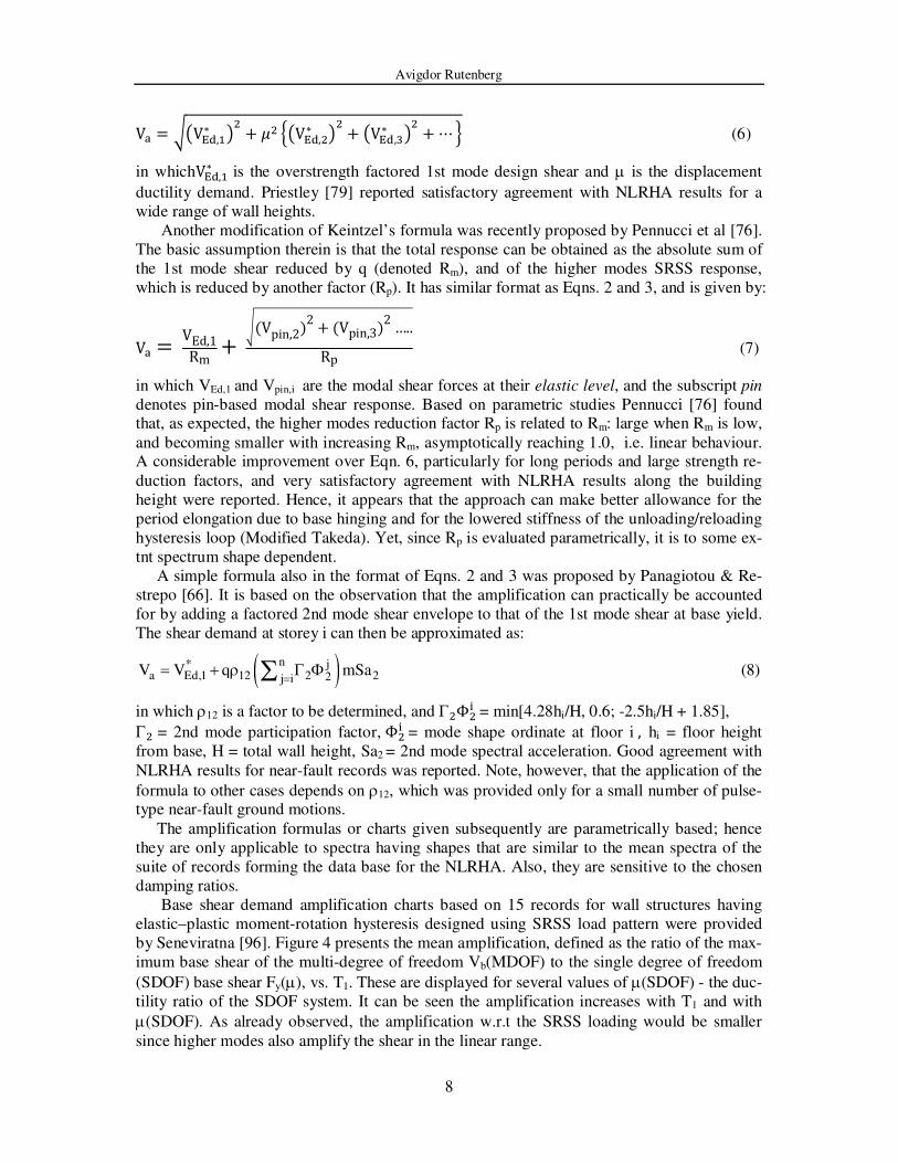
V� = ��V��,∗ �� + �� ��V��,�∗ �� + �V��,�∗ �� +⋯� (6)
in whichV��,∗ is the overstrength factored 1st mode design shear and µ is the displacement
ductility demand. Priestley [79] reported satisfactory agreement with NLRHA results for a
wide range of wall heights.
Another modification of Keintzel’s formula was recently proposed by Pennucci et al [76].
The basic assumption therein is that the total response can be obtained as the absolute sum of
the 1st mode shear reduced by q (denoted Rm), and of the higher modes SRSS response,
which is reduced by another factor (Rp). It has similar format as Eqns. 2 and 3, and is given by:
V� =VEd,1Rm +�(Vpin,2)2+(Vpin,3)2…..Rp (7)
in which VEd,1 and Vpin,i are the modal shear forces at their elastic level, and the subscript pin
denotes pin-based modal shear response. Based on parametric studies Pennucci [76] found that, as expected, the higher modes reduction factor Rp is related to Rm: large when Rm is low,
and becoming smaller with increasing Rm, asymptotically reaching 1.0, i.e. linear behaviour. A considerable improvement over Eqn. 6, particularly for long periods and large strength re-
duction factors, and very satisfactory agreement with NLRHA results along the building
height were reported. Hence, it appears that the approach can make better allowance for the
period elongation due to base hinging and for the lowered stiffness of the unloading/reloading
hysteresis loop (Modified Takeda). Yet, since Rp is evaluated parametrically, it is to some ex-
tnt spectrum shape dependent.
A simple formula also in the format of Eqns. 2 and 3 was proposed by Panagiotou & Re-
strepo [66]. It is based on the observation that the amplification can practically be accounted
for by adding a factored 2nd mode shear envelope to that of the 1st mode shear at base yield.
The shear demand at storey i can then be approximated as:
( )n j*a Ed,1 12 2 22j i
V V q mSa=
= + ρ Γ ΦΣ (8)
in which ρ12 is a factor to be determined, and Γ�Φ�$ = min[4.28hi/H, 0.6; -2.5hi/H + 1.85],
Γ� = 2nd mode participation factor, Φ�$ = mode shape ordinate at floor i ,hi = floor height
from base, H = total wall height, Sa2 = 2nd mode spectral acceleration. Good agreement with
NLRHA results for near-fault records was reported. Note, however, that the application of the
formula to other cases depends on ρ12, which was provided only for a small number of pulse-type near-fault ground motions.
The amplification formulas or charts given subsequently are parametrically based; hence
they are only applicable to spectra having shapes that are similar to the mean spectra of the
suite of records forming the data base for the NLRHA. Also, they are sensitive to the chosen
damping ratios.
Base shear demand amplification charts based on 15 records for wall structures having
elastic–plastic moment-rotation hysteresis designed using SRSS load pattern were provided
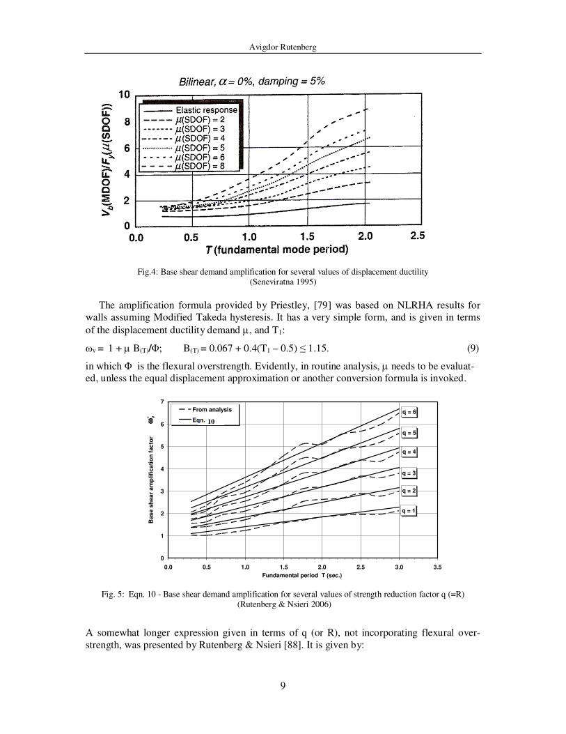
by Seneviratna [96]. Figure 4 presents the mean amplification, defined as the ratio of the max-
imum base shear of the multi-degree of freedom Vb(MDOF) to the single degree of freedom
(SDOF) base shear Fy(µ), vs. T1. These are displayed for several values of µ(SDOF) - the duc-
tility ratio of the SDOF system. It can be seen the amplification increases with T1 and with
µ(SDOF). As already observed, the amplification w.r.t the SRSS loading would be smaller
since higher modes also amplify the shear in the linear range.
Avigdor Rutenberg
9
Fig.4: Base shear demand amplification for several values of displacement ductility
(Seneviratna 1995)
The amplification formula provided by Priestley, [79] was based on NLRHA results for
walls assuming Modified Takeda hysteresis. It has a very simple form, and is given in terms
of the displacement ductility demand µ, and T1:
ωv = 1 + µ B(T)/Φ; B(T) = 0.067 + 0.4(T1 – 0.5) ≤ 1.15. (9)
in which Φ is the flexural overstrength. Evidently, in routine analysis, µ needs to be evaluat-
ed, unless the equal displacement approximation or another conversion formula is invoked.
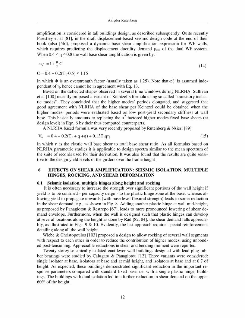
Fig. 5: Eqn. 10 - Base shear demand amplification for several values of strength reduction factor q (=R)
(Rutenberg & Nsieri 2006)
A somewhat longer expression given in terms of q (or R), not incorporating flexural over-
strength, was presented by Rutenberg & Nsieri [88]. It is given by:
q = 6
q = 5
q = 4
q = 3
q = 2
q = 1
0
1
2
3
4
5
6
7
0.0 0.5 1.0 1.5 2.0 2.5 3.0 3.5
Fundamental period T (sec.)
Bas
e s
he
ar
am
plifi
ca
tio
n f
ac
tor
From analysis
Eqn. 4ωω ωω
∗ v
10

Avigdor Rutenberg
10
Va = [0.75 + 0.22(T1 + q +T1q] Vd (10)
in which Vd is the base shear due to a triangularly distributed base shear. Eqn. 10 is shown in
Fig. 5 by the straight lines. Elastic-plastic response and 5% tangent stiffness damping in the
1st and 5th modes were assumed. Note that 5% damping is now believed to be too high for
very tall buildings (e.g. [92]), for which the major sources of damping have a lower effect.
4 STOREY SHEAR DEMAND
Whereas, as noted, Eqns. 6, 7 and 8 are able to predict the shear demand for the full wall
height, this is not the case with the other design equations listed above, that apply only to the
base shear. This is because in many cases the ωv normalized SRSS storey shears overestimate
the expected shear values for large wall portions of long period structures, as shown in Fig. 6.
Fig.6: 40-storey wall shear envelopes: code loading design pattern, T = 2.05s: mean for S1,a records, bilinear,
α = 0% , damping 5% (Seneviratna & Krawinkler 1997)
Apparently, this problem was first addressed by Iqbal & Derecho [42] who provided a wall height shear demand envelope that has not changed appreciably since. A design envelope as
function of the fundamental period T1 is shown in Fig. 7, in which ξ is given by:
ξ = 1 – 0.3T1 ≥ 0.5 (11)
Note that Eqn.11 resembles Fig. 5.4 in EC8 [16], but therein it is confined to walls in dual WF
systems. A similar but straight-line envelope with the wall-top shear of:
(0.9 – 0.3T1) Va ≥ 0.3 Va , (12)
was given by Priestley et al [81] and Model Code [56].
0 0.3 0.6 0.9 1.2 1.5
Rel
ati
ve
Hei
gh
t
1.0
0.8
0.6
0.4
0.2
0.0
Vi / Vbase
Vdyn, i / Vdyn, base (µµµµ (SDOF)=4) Vdyn, i / Vdyn, base (µµµµ (SDOF)=4)
Vdes, i / Vdes, base (UBC 94) Vdyn, i / Vdyn, base (Elas. Resp)

Avigdor Rutenberg
11
d
*
vV0.5ω
0.1H
H
d
*
vVω
H⋅ξ
Fig.7: Shear force design envelope (Rutenberg & Nsieri 2006)
5 MORE ON DUAL WALL FRAME (WF) SYSTEMS
Some studies on dynamic shear demand amplification in WFs followed naturally from
those on flexural walls, but not all. As already noted wall shear amplification in WFs was studied by Kabeyasawa (e.g. [44]) and Aoyama [4], see Eqn. 2. Paulay and his co-workers [38,
39] observed that, as in flexural walls, higher vibration modes amplified the shear force de-
mand on the walls of WFs, but to a lesser extent, and proposed a simple prediction formula
accounting for this response reduction. This extension of the shear amplification formula for
flexural walls based on Blakeley et al [9] to walls of dual systems is also given by Paulay &
Priestley [75]. This WF shear amplification factor ωv* is given by:
ωv* = 1 + (ωv -1) η (13)
in which ωv is the free standing wall shear amplification factor and η is the fraction of the base
shear carried by the walls. Although the format of this formula is appealing its predictive ca-
pability appears to be limited [89].
Alwely [3] made ωv* dependent on the non-dimensional frame-to-wall stiffness ratio αH,
as evaluated from the linear continuum approximation (e.g. [99]). Kappos & Antoniadis [46] proposed a procedure to estimate more realistically the shear demand in the upper storeys and
also a modified version of the Goodsir et al [38, 39] formula (Eqn. 13) to account for shear amplification in WFs with unequal walls. Very recently Kappos & Antoniadis [47, 48] pro-
vided formulas to improve the shear distribution match with NLRHA results all along the wall
height.
The codified guidance regarding the amplification factor ωv* is rather limited. The New
Zealand seismic code NZS 3101- 2006 [63] refers only to Paulay & Priestley [75] where Eqn.
13 is presented. Note that therein ωv is that given by Eqn. 1. It is clearly seen that when η
≤ 1.0 then 1 ≤ ωv*≤ ωv. Eqn. 13 assumes that ωv
*, as ωv, is independent of the expected ductil-
ity demand or q (R). Note also that Eqn. 1 depends indirectly on T1 through its dependence on
the number of storeys n.
EC8 [16] considers WFs in which η > 50% as “wall–equivalent”, hence in such cases wall
shear in high ductility class (DC-H) systems should be amplified per Eqn. 4.
Applicable US codes do not include dynamic shear amplification requirements even for
flexural walls (except the Commentary to the 1999 SEAOC code [93]). In practice, however,
Avigdor Rutenberg
12
amplification is considered in tall buildings design, as described subsequently. Quite recently
Priestley et al [81], in the draft displacement-based seismic design code at the end of their
book (also [56]), proposed a dynamic base shear amplification expression for WF walls,
which requires predicting the displacement ductility demand µsys of the dual WF system.
When 0.4 ≤ η ≤ 0.8 the wall base shear amplification is given by:
*v 1 C
µΦ
ω = + (14)
C = 0.4 + 0.2(T1-0.5) ≤ 1.15
in which Φ is an overstrength factor (usually taken as 1.25). Note that ω%∗ is assumed inde-
pendent of η, hence cannot be in agreement with Eq. 13.
Based on the deflected shapes observed in several time windows during NLRHA, Sullivan
et al [100] recently proposed a variant of Keintzel’s formula using so called “transitory inelas-
tic modes”. They concluded that the higher modes’ periods elongated, and suggested that good agreement with NLRHA of the base shear per Keintzel could be obtained when the
higher modes’ periods were evaluated based on low post-yield secondary stiffness at wall
base. This basically amounts to replacing the µ2 factored higher modes fixed base shears (at
design level) in Eqn. 6 by their thus computed counterparts.
A NLRHA based formula was very recently proposed by Rutenberg & Nsieri [89]:
Va = 0.4 + 0.2(T1 + q +η) + 0.13T1qη (15)
in which η is the elastic wall base shear to total base shear ratio. As all formulas based on NLRHA parametric studies it is applicable to design spectra similar to the mean spectrum of
the suite of records used for their derivation. It was also found that the results are quite sensi-
tive to the design yield levels of the girders over the frame height
6 EFFECTS ON SHEAR AMPLIFICATION: SEISMIC ISOLATION, MULTIPLE
HINGES, ROCKING, AND SHEAR DEFORMATION
6.1 Seismic isolation, multiple hinges along height and rocking It is often necessary to increase the strength over significant portions of the wall height if
yield is to be confined - per capacity deign - to the plastic hinge zone at the base; whereas al-
lowing yield to propagate upwards (with base level flexural strength) leads to some reduction
in the shear demand, e.g., as shown in Fig. 8. Adding another plastic hinge at wall mid-height,
as proposed by Panagiotou & Restrepo [67], leads to more pronounced lowering of shear de-
mand envelope. Furthermore, when the wall is designed such that plastic hinges can develop
at several locations along the height as done by Rad [82, 84], the shear demand falls apprecia-
bly, as illustrated in Figs. 9 & 10. Evidently, the last approach requires special reinforcement
detailing along all the wall height.
Wiebe & Christopoulos [103] proposed a design to allow rocking of several wall segments
with respect to each other in order to reduce the contribution of higher modes, using unbond-
ed post-tensioning. Appreciable reductions in shear and bending moment were reported.
Twenty storey seismically isolated cantilever wall buildings designed with lead-plug rub-
ber bearings were studied by Calugaru & Panagiotou [12]. Three variants were considered: single isolator at base, isolators at base and at mid height, and isolators at base and at 0.7 of
height. As expected, these buildings demonstrated significant reduction in the important re-sponse parameters compared with standard fixed base, i.e. with a single plastic hinge, build-
ings. The buildings with dual isolation led to a further reduction in shear demand on the upper
60% of the height.

Avigdor Rutenberg
13
Fig.8: Plastic hinge at base only vs. plastification at higher levels –base shear flexural strength assumed over building height (Rutenberg & Nsieri 2006)
6.2 Shear deformation
Already in 1988 Eibl & Keintzel [27] observed that smaller shear rigidity lowers the higher
modes dynamic amplification. In their study on the shear distribution among wall of different lengths Rutenberg & Nsieri [88] noted a substantial lowering in shear demand in cracked sec-
tions when the effective shear rigidity GAve was evaluated based on the analogous truss model [72], which is appreciably smaller than the recommended values based on the gross section
(GAvg) for both cracked and uncracked walls by ASCE 41-06 [6], or 50% thereof for cracked walls by EC8 [16]. Gerin & Adebar [33] provided expressions to predict the shear defor-
mation, including shear cracking and yielding, observing that a typical effective shear rigidity
of diagonally cracked concrete could approximately be taken as 10% GAvg, somewhat lower
than the GAve assumed by [88]. Rad & Adebar [82, 84] used effective shear stiffness as a
simple way to demonstrate the significant influence of cracking on shear amplification, as
shown in Fig 11. Wallace [102] suggested modelling the post-cracking shear stiffness in the
plastic hinge zone as circa 2.5% GAvg.
7 NOTES ON PRACTICE IN THE USA
Seismic design practice in the US, particularly in California, is highly regarded worldwide and often adopted; hence it may be useful to comment on the situation there with respect to
dynamic shear amplification.
It is interesting that although researchers, code-writers and practicing engineers were ex-
posed to the many publications on the post-yield shear demand magnification of higher modes,
this has not been manifested in US seismic codes, e.g., ASCE 7-05 [5], as would be expected,
particularly, since other major codes such as NZ3101 [63] and EC8 [16] included such provi-
sions for many years. As noted, only the Commentary to the 1999 SEAOC [93] considered
this issue, referring the reader to the New Zealand code. Also, shear amplification is recog-
nized, albeit to a limited extent, by ASCE 41-06 [6] code for upgrading of existing buildings:
q = 3
q = 1
q = 6
q = 4
q = 5
q = 2
0
1
2
3
4
5
6
0.0 0.5 1.0 1.5 2.0 2.5
Fundamental period T (sec.)
Ba
se
sh
ear
am
pli
fic
ati
on
fac
tor
Plastic hinge at base
Plastic hinges allowed at higher levels
q = 2, 3, 4, 5, 6

Avigdor Rutenberg
14
Fig. 9: Shear force envelopes with hinging permitted only at wall base, R =5 (Rad & Adebar 2008)
Fig. 10: Shear force envelopes, flexural hinging at many locations over height, R =5 (Rad & Adebar 2008)
Fig. 11: Influence of effective shear stiffness on average shear force envelopes, flexural hinging at many
locations along wall height, R =5 (Rad & Adebar 2008)
Avigdor Rutenberg
15
the shear force at the wall base is calculated assuming uniform lateral force distribution over
the wall height, i.e., the shear resultant is located at wall mid-height (clause 6.7.2.4 therein)
rather than at approximately its 2/3rd, thereby increasing the base shear by circa 35%. It is
only when NLRHA - one of the recommended procedures by US codes - is carried out that
dynamic shear amplification is accounted for. However, code based analysis per this proce-
dure appears to be the exception rather than the rule.
The resurgence in high-rise construction in the west coast of the United States during the
early and mid-2000’s has led to the application of performance-based non-prescriptive design
procedures ([20, 54, 94]. Such design requires using a suite of at least seven pairs of appropri-
ate ground motion histories; hence, dynamic amplification is thereby considered. Indeed, re-
searchers and practitioners in California were soon reporting on large higher modes magnifications [53, 57, 58, 59, 105]. For very tall buildings, circa 40 storeys, these studies
predicted shear amplifications on the order of 4 relative to code. It is interesting to note that one designer [52] observed, after designing over two dozen tall buildings, that “design which
follows the prescriptive provisions of the building code will likely result in a shear capacity
that falls well short of the likely demands the structure will experience during a significant
seismic event. As shear failure of a structural wall is typically viewed as non-ductile, undesir-
able response, this outcome raises serious concerns….”
8 POST-ELASTIC REDISTRIBUTION OF SHEAR DEMAND AMONG WALLS IN
SYSTEMS WITH INTERCONNECTED WALLS OF UNEQUAL LENGTH.
The shear force distribution among the walls in regular multistorey structures laterally
supported by a number of reinforced concrete cantilever walls with markedly different lengths is strongly affected by the different yield displacement levels of the walls. In the post-elastic
range the share of the shear force carried by the shorter walls is larger than their share in the bending moment.
In a single storey structure the shear distribution among the walls within the elastic range is proportional to their stiffness. Following yielding of the longer wall additional loads will be
carried by the shorter ones. It is evident that design for shear on the basis of relative stiffness
underestimates the forces on the shorter walls since shear capacity should be made propor-
tional to flexural strength. However, the situation in a multistory building is different as
shown in Fig.12, showing a simplistic model of a two storey system supported by two walls.
To fix ideas, assume Wall 2 is very much stiffer than Wall 1; hence, the horizontal force on
Wall 1 is negligible so long as Wall 2 has not yielded. With Wall 2 yielding at base the force
∆H is distributed as shown in Fig.12b, where for simplicity it was assumed that the floor dia-
phragms are pin-connected to the walls and are infinitely rigid in plane. It can be seen that displacement compatibility requires a shear force redistribution resulting in a very large shear
force acting on Wall 1.
Rutenberg and coworkers (e.g. [85, 86, 88]) demonstrated that the shear demand on the
flexible walls could be very much larger than commensurate with their relative stiffness or
even flexural strength. These studies were mainly carried out by means of cyclic pushover
analysis on bilinear force-displacement hysteretic models. However, since redistribution is
mainly due to compatibility enforcement rather than equilibrium it is sensitive to modelling
assumptions. Hence further studies replaced the routine modelling (G= 0.4E, in-plane floor
rigidity, bilinear hysteresis) with more realistic models. Indeed, the earlier results were shown
[7, 88] to overestimate the base shear demand on the shorter wall. Beyer [7] also observed
that the greatest effect was due to “locking in” of compatibility forces transmitted by the floor
diaphragms. Yet, it appears that the effect of this relaxation depends on the extent of plasticity

Avigdor Rutenberg
16
Fig. 12: Two-storey wall system: (a) properties and loading, (b) floor forces and deflected shapes
(Rutenberg 2004)
propagation along the wall’s cross-section, which in turn depends on whether the longitudinal reinforcement is mainly concentrated at the wall ends (flanges) or is uniformly distributed,
which was not considered. Also, Beyer’s conclusions were obtained from a two-wall model with modest lengths ratio (1.5: 6.0m & 4.0m respectively); more pronounced stiffness differ-
ences are likely to increase the share of the short wall shear force. However, Priestley et al [81] concluded, based on Beyer’s work [7], that these compatibility induced forces might
normally be ignored in design. Further study on redistribution, including these effects, is now under way [8].
Beyer [7] proposed using the pushover analysis [85] to test the propensity of the shorter wall for excessive shear demand. In that procedure the resultant lateral force is located at the
minimum dynamic effective height heq, dyn given by Eqn.16:
heq, dyn = heq, static / ωv (16)
In which heq, static is the height of the statically computed shear resultant, and ωv is the dynamic
amplification factor. Alternatively, heq, dyn may be taken for the applicable spectrum from
plots such as Fig. 2 in [91], if available. If the base shear on the short wall sharply increases
while the base shear of the long wall drops off after formation of the plastic hinge at the base
of the long wall, coupling effects are expected to be significant. Note that ωv in Eqn. 16 is predicated on the assumption that the total base shear on a group of walls is equal to that on
an isolated wall whose strength and stiffness equal the respective sums of these properties of the individual walls. This was found to be justified for the record suites used by Rutenberg &
Nsieri [88]. Adebar & Rad [1], using pushover analysis, studied a two-wall system with markedly dif-
ferent properties (a long flanged wall and a short rectangular one). They were mainly interest-ed in the effect of shear deformation on the response, modelling both flexure and shear with
tri-linear force displacement relations, i.e., a kink at cracking and a yielding plateau (very short for shear). As expected, cracking and yielding were found to affect the shear force redis-
tribution along the height, in some cases predicting shear failure. In particular, diagonal shear
Wall 1 Wall 2
(a) (b)
∆∆∆∆H ∆∆∆∆H 1.5∆∆∆∆H
h
h
3∆∆∆∆H
I1 (I1<<) I2
I1 (I1<<) I2
2.5∆∆∆∆H 1.5∆∆∆∆H

Avigdor Rutenberg
17
cracking led to significant shear force increase in the short wall at the 2nd floor level. Note,
however, that concentrated plasticity was not accounted for.
9 DISCUSSION
In many countries dynamic shear amplification is now routinely accounted for in wall de-
sign, yet, as shown, there are large differences in the extent of amplification - from relatively low ωv in the New Zealand code to quite high ones in EC8. As already noted, the Canadian
code requires considering amplification only when the equivalent lateral force procedure is carried out, and then only the linear multi-modal effect. Interestingly, the Romanian seismic
code P100-1/2006 [64], while generally adopting the EC8 provisions for RC structures, ex-
cluded Eqn. 4, based mainly on the peculiarities of the 1977 Vrancea earthquake record. In-
stead, it specifies ωv = 1.5 for statically computed base shear or 1.2Φ (Φ = flexural
overstrength), whichever is larger [77, 104].
The very large amplifications predicted by NLRHA were met in many instances with some
skepticism. For a widely expressed attitude it is perhaps best to quote Paulay [74], who wrote
w. r. t. computed magnifications much larger than given in the New Zealand provisions: “I
found at that time (early 1980’s, AR) that the duration of predicted extremely high shear de-
mands was typically 0.02 to 0.03 seconds. So we pacified our conscience with the unanswered
question: ‘is this time interval long enough to enable a wall region to fail in shear?’”. On the
other hand, ignoring shear peaks with durations less than 0.03 seconds do not appear to lead
to substantial reduction in shear demand. A preliminary study by Panagiotou & Calugaru [65]
on records of three earthquakes showed that demand was lowered only by 6%-15%. It has often been observed that the maximum shear may not occur simultaneously with
maximum moment over the wall height; hence the large amplification factors could be ques-tioned (e.g. [55]). Yet, simultaneous peaks at wall base level were observed in analyses by
Rad [82] and Tremblay et al [101] for several historical records; and the large amplifications were evaluated for the wall base. No doubt these two issues deserve study.
The main reason for the skepticism appears to be the feeling that standard nonlinear mod-elling of RC walls, particularly in the plastic hinge zone, does not capture faithfully the com-
plex response. As noted above, using the Takeda rather than the bilinear hysteresis lowers
computed shear demand somewhat, and more importantly, realistic shear behaviour modelling
results in substantial fall in shear demand (Fig. 11); considering shear-flexure interaction
might lower it further. On the other hand, it has been demonstrated that the 5% damping rou-
tinely assumed in NLRHA is quite unconservative for tall buildings design, and damping rati-
os lower than 2% were reported (e.g. [92]).
Another important issue is the experimental and historical evidence for nonlinear dynamic
shear amplification The study by Eberhard [25, 26, 98] on wall frames suggests that the for-mula proposed by Kabeyasawa (e.g. [43]) and Aoyama [4] is in approximate agreement with
the experimental results. The experimental study by Panagiotou et al [66, 68, 69] did not fo-
cus on shear amplification per se, yet this phenomenon has been observed in their shake table
tests. Shear amplification was also observed by Tremblay, Leger and their co-workers in an
on-going shake-table testing program [55]. The large dynamic amplifications predicted by the
many parametric studies listed in the bibliography and by Keintzel’s formula, or variations
thereof, were not observed in these studies.
On the whole it appears that the seismic performance of well-designed and constructed
cantilever wall buildings has been satisfactory. Yet, damage to shear walls was reported after
several earthquakes. Blakeley et al [9] referred to reports on two cases of extensive diagonal
tension cracking; however, it is not clear whether those or other such failures can be attributed
to dynamic shear amplification. Shear failures in walls were observed after the February 2010

Avigdor Rutenberg
18
Chile earthquake, but these were attributed mainly to discontinuities and similar effects such
as stress concentrations near openings. Targeted studies are now under way [11].
The reader who chooses not to perform NLRHA with refined modelling may well ask
which of the several formulas reviewed here he/she should adopt. In order to answer this
question it is necessary to perform extensive parametric studies. On the other hand it does not
appear that the differences among the several variants of Keintzel’s formula are excessive.
Strictly speaking, parametrically derived formulas and design charts are applicable only to the
mean spectrum of their data base.
These design procedures do not account for multiple hinges when the vertical wall rein-
forcement follows approximately (in several steps) modal analysis moment envelope. They
also do not consider wall shear cracking, which has significant effect on shear amplification, and on the response of interconnected walls. The actual impact of shear cracking on amplifi-
cation depends on cyclic shear-flexure coupling; but such a model is not yet available [102]. In view of the above, it is believed that judiciously conceived NLRHA-based design can
better account for the many variables affecting dynamic shear amplification.
10 ACKNOWLEDGEMENTS
The author is indebted to T. Postelnicu and D. Zamfirescu for explaining the relevant
provisions in the Romanian code P100-1/2006, to M. Panagiotou for providing peak shear
plots for several US records and to K. Beyer for her comments on interconnected walls. The
help of R. Adoni, A. Aines and I. Elkayam is gratefully acknowledged.
REFERENCES AND BIBLIOGRAPHY
The list below, although quite extensive, is by no means exhaustive, as can be seen from
relevant publications referred to in some of the listed publications. Research reports subse-
quently published in conference proceedings or journals are usually not included.
[1] Adebar P & Rad BR (2007). Seismic shear force distribution in high-rise concrete walls.
9th Canadian Conference on Earthquake engineering, Ottawa, Canada.
[2] Adebar P, Mutrie J & DeVall R (2005). Ductility of concrete walls: the Canadian seis-
mic design provisions 1984 to 2004. Canadian Journal of Civil Engineering, 32, 6,
1124-1137.
[3] Alwely F (2004). Seismic behavior of ductile wall-frame structural systems. M. Sc.
Thesis, Faculty of Civil & Environmental Engineering, Technion, Haifa, Israel (in He-
brew, English summary & captions).
[4] Aoyama H (1987). Earthquake resistant design of reinforced concrete frame buildings
with “flexural” walls. Journal Faculty of Engineering, University of Tokyo, XXXIX, 2, 87-109. Also in: Earthquake resistance of reinforced concrete structures, a volume
honoring Hiroyuki Aoyama, University of Tokyo, 1993.
[5] ASCE (2006) Minimum design loads for buildings and other structures. ASCE Standard
ASCE/SEI 7-05. American Society of Civil Engineers, Reston, VA.
[6] ASCE (2007). Seismic rehabilitation of existing buildings. ASCE Standard ASCE/SEI
41-06. American Society of Civil Engineers, Reston, VA.
[7] Beyer K (2005). Design and analysis of walls coupled by floor diaphragms. M.Sc. thesis,
Rose School, University of Pavia, Italy.

Avigdor Rutenberg
19
[8] Beyer K (2011). Personal communication, February.
[9] Blakeley RWG, Cooney RC & Megget LM (1975). Seismic shear loading at flexural
capacity in cantilever wall structures. Bulletin New Zealand National Society Earth-
quake Engineering, 8, 278-290.
[10] Boivin Y & Paultre P (2010). Seismic performance of a 12-storey ductile concrete shear
wall system designed according to the 2005 National building code of Canada and the
2004 Canadian Standard Association standard A23.3. Canadian Journal of Civil Engi-
neering, 37, 1-16.
[11] Boroschek ( 2011). Personal communication, January.
[12] Calugaru V. & Panagiotou M (2010). Seismic Isolation Using Single and Dual Shear
Hinging of Tall Cantilever Wall Buildings Subjected to Near Fault Ground Motions. 9th US National & 10th Canadian Conference on Earthquake Engineering, Toronto,
Canada.
[13] CEB (1980, 1983, 1985). Model Code for Seismic Design of Concrete Structures, Bul-
letin d’Information, Comite Europeen du Beton, No.133, 160, 165 (respectively), Lau-
sanne, Switzerland.
[14] CEN (1988). Eurocode No 8 – Structures in seismic regions –Design. Part 1 General and building”. Brussels, Belgium.
[15] CEN (1993). Eurocode 8 - Earthquake resistant design of structures. Pt. 1.3 General
rules – seismic actions and general requirements for structures. Final Draft PrENV,
Brussels, Belgium.
[16] CEN (2004). Eurocode 8 - Earthquake resistant design of structures. Pt. 1.3 General
rules – specific rules for various materials and elements”, Brussels, Belgium.
[17] Chaallal O & Gauthier D (2000). Seismic shear demand on wall segments of ductile
coupled shear walls. Canadian Journal of Civil Engineering, 27, 506-522.
[18] Chopra, AK (2001). Dynamics of Structures, 2nd edn. Prentice Hall, Upper Saddle Riv-
er, NJ.
[19] CSA (1994, 2004). Design of concrete structures. Standard CAN/CSA-A23.3-04, Cana-
dian Standards Association, Rexdale, Canada.
[20] CTBUH (2008). Recommendations for the seismic design of high-rise buildings. Coun-
cil on Tall Buildings and Urban Habitat, Chicago, IL.
[21] Derecho AT et al (1978). Structural walls in earthquake-resistant buildings – Analytical
investigations, dynamic analysis of isolated structural walls – Parametric Studies. Final
Report to the National Science Foundation RANN, Portland Cement Association, Skok-
ie, IL.
[22] Derecho AT, Iqbal M & Corley WG (1980). Determining design force levels for earth-
quake-resistant reinforced concrete structural walls. 7th World Conference on Earth-
quake Engineering, Istanbul, Turkey, Vol. 5.
[23] Derecho AT et al. (1981). Structural walls in earthquake resistant buildings, dynamic
analysis of isolated structural walls - development of design procedure, design force
level. Final Report to the National Science Foundation ASRA, Construction Technolo-
gy Laboratories, PCA, Skokie, IL.

Avigdor Rutenberg
20
[24] Derecho AT & Corley, WG (1984). Design requirements for structural walls in multi-
story buildings. 8th World Conference on Earthquake Engineering, San Francisco, CA,
Vol. 5.
[25] Eberhard MO & Sozen MA (1989). Experiments and analyses to study the seismic re-
sponse of reinforced concrete frame-wall structures with yielding columns, Structural Research Series 548, Civ. Engrg. Studies, University of Illinois, Urbana, IL.
[26] Eberhard MO & Sozen MA (1993). Behavior-based method to determine design shear
in earthquake-resistant walls. Journal of Structural Engineering ASCE, 119, 2, 619-640.
[27] Eibl J & Keinzel E (1988). Seismic shear forces in RC cantilever shear walls. 9th World
Conference on Earthquake Engineering, Tokyo-Kyoto, Vol. VI.
[28] fib (2010). Model Code 2010, First complete draft, Vol. 2. International Federation for Structural Concrete, Lausanne, Switzerland.
[29] Filiatrault A, Anderson DL & DeVall R (1992). The effect of weak foundation on the
seismic response of core wall type buildings. Canadian Journal of Civil Engineering,
19, 530-539.
[30] Filiatrault A, D’Aronco D & Tinawi R (1994). Seismic shear demand of ductile canti-
lever walls: a Canadian perspective. Canadian Journal of Civil Engineering, 21, 363-376.
[31] Fischinger M , Isakovic T & Rejec K (2010a). Seismic Behavior of RC Structural Walls
and Eurocode 8 Provisions. 9th US National & 10th Canadian Conference on Earth-
quake Engineering, Toronto, Canada.
[32] Fischinger M, Rejec K & Isakovic T (2010b). Shear magnification factors for RC Struc-
tural Walls in Eurocode 8. 14th European Conference on Earthquake Engineering,
Ohrid, Macedonia.
[33] Gérin M & Adebar P ( 2004). Accounting for shear in seismic analysis of concrete structures, 13th World Conference on Earthquake Engineering, Vancouver, Canada.
[34] Ghorbanirenani, I et al (2009a). Distribution of inelastic demand in slender R/C shear
walls subjected to Eastern North America ground motion. ATC-SEI Conference on Im-
proving the Seismic Performance of Existing Buildings and Other Structures, San Fran-
cisco, CA.
[35] Ghorbanirenani I et al (2009b). Shake table tests and repair of ductile slender reinforced
concrete shear walls. 9th US National & 10th Canadian Conference on Earthquake En-
gineering, Toronto, Canada.
[36] Ghosh SK (1992). Required shear strength of earthquake-resistant reinforced concrete
shear walls, in: Nonlinear seismic analysis and design of reinforced concrete buildings, P. Fajfar & H. Krawinkler eds., Elsevier, London.
[37] Ghosh SK & Markevicius VP (1990). Design of earthquake resistant shearwalls to pre-
vent shear failure. 4th US National Conference on Earthquake Engineering, Palm
Springs, CA, Vol. 2.
[38] Goodsir WJ, Paulay T & Carr AJ (1983). A study of the inelastic seismic response of reinforced concrete coupled frame-shear wall structures. Bulletin New Zealand National
Society for Earthquake Engineering, 16, 3, 185-200.

Avigdor Rutenberg
21
[39] Goodsir WJ, Paulay T & Carr AJ (1984). A design procedure for interacting wall-frame
structures under seismic actions. 8th World Conference on Earthquake Engineering,
San Francisco, CA, Vol. 5.
[40] Humar JL & Rahgozar MA (2000). Application of uniform hazard spectra in seismic
design of multistorey buildings. Canadian Journal of Civil Engineering, 27, 563-580.
[41] Humar J & Mahgoub MA (2003). Determination of seismic design forces by equivalent
static load method. Canadian Journal of Civil Engineering, 30, 287-303.
[42] Iqbal M & Derecho AT (1980). Inertia forces over height of reinforced concrete struc-
tural walls during earthquakes, in: Reinforced concrete structures subjected to wind and
earthquake forces. ACI Publication SP-63, American Concrete Institute, Detroit, MI.
[43] Kabeyasawa T & Ogata K (1984). Ultimate-state design of RC wall-frame structures, Transaction of the Japan Concrete Institute, 629- 636.
[44] Kabeyasawa T (1987). Ultimate-state design of RC wall-frame structures, Pacific Con-
ference Earthquake Engineering, Auckland, New Zealand, Vol. 1. Also in: Earthquake
resistance of reinforced concrete structures, a volume honoring Hiroyuki Aoyama,
University of Tokyo, Tokyo, 431- 440, (1993).
[45] Kabeyasawa T (1988). Evaluation of column and wall actions in the ultimate state de-sign of reinforced concrete structures. 9th World Conference on Earthquake Engineer-
ing, Tokyo-Kyoto, Vol. VIII.
[46] Kappos AJ & Antoniadis, P (2007). A contribution to seismic shear design of R/C
walls in dual systems. Bulletin of Earthquake Engineering, 5, 3, 443-466.
[47] Kappos AJ & Antoniadis PS (2010). An improved procedure for the seismic design of
reinforced concrete walls in dual systems. 14th European Conference on Earthquake
Engineering, Ohrid, Macedonia.
[48] Kappos AJ & Antoniadis PS (2011). Evaluation and suggestions for improvement in of seismic design procedures for RC walls. Earthquake Engineering and Structural Dy-
namics, 40, 35-53.
[49] Keintzel E (1984). Ductility requirements for shear wall structures in seismic areas. 8th
World Conference on Earthquake Engineering, San Francisco, CA, Vol. 5.
[50] Keintzel E (1990) Seismic design shear forces in reinforced concrete cantilever shear
wall structures. European Journal of Earthquake Engineering, 3, 7-16.
[51] Keintzel E (1992). Advances in the design for shear of RC structural walls under seis-
mic loading, in: Nonlinear seismic analysis and design of reinforced concrete buildings, P. Fajfar & H. Krawinkler eds., Elsevier, London.
[52] Klemencic R (2008). Performance based seismic design – rising. Structure- Magazine,
June, 10-13.
[53] Klemencic R et al (2007). Performance-based design of ductile concrete core wall
buildings – issues to consider before detailed analysis. The Structural Design of Tall
and Special Buildings, 16, 599-714.
[54] LATBSDC (2005, 2008). An Alternative Procedure for Seismic Analysis and Design of
Tall Buildings Located in the Los Angeles Region, Los Angeles Tall Buildings Struc-
tural Design Council, CA.

Avigdor Rutenberg
22
[55] Leger P (2010). Personal communication, March.
[56] Model Code for Displacement-Based Design (2009). GM Calvi & TJ Sullivan, eds.
DBD09, draft subject to public scrutiny, IUSS Press, Pavia, Italy.
[57] Moehle JP (2006) Seismic analysis design and review for tall buildings. The Structural
Design for Tall and Special Buildings, 15, 5, 495-513.
[58] Moehle JP (2008). Performance-based seismic design of tall buildings in the U.S. 14th
World Conference on Earthquake Engineering, Beijing, China.
[59] Moehle J, Bozorgnia Y & Yang TY (2007). The Tall Buildings Initiative. SEAOC Con-
vention, Squaw Creek, CA, 315-324.
[60] Naeim F ed. (2001). The Seismic Design Handbook, 2nd edn. Kluwer Academic, Bos-
ton, MS.
[61] NBCC (1995, 2005). National Building Code of Canada. Associate Committee on the
National Building Code. National Research Council of Canada, Ottawa.
[62] Nsieri E (2004). The seismic nonlinear behaviour of ductile reinforced concrete cantile-
ver wall systems. M.Sc. thesis, Technion, Haifa, Israel (in Hebrew, English summary &
captions).
[63] NZS (1982, 1995, 2006) “NZS 3101: Part1, Concrete Structures Standard; Part 2, Commentary on the design of concrete structures, New Zealand Standards, Wellington.
[64] P100-1/2006 (2006). Seismic design code P100 Part 1- Design provisions for buildings.
Technical University of Construction, Bucharest, September, (in Romanian).
[65] Panagiotou M (2011). Personal Communication, January.
[66] Panagiotou M & Restrepo JI (2007). Lessons learnt from the UCSD full-scale shake ta-
ble testing on a 7-story residential building. SEAOC Convention, Squaw Creek, CA.
[67] Panagiotou M & Restrepo JI (2009). Dual-plastic hinge design concept for reducing
higher-mode effects on high-rise cantilever wall building. Earthquake Engineering and
Structural Dynamics, 38, 12, 1359-1380.
[68] Panagiotou M & Restrepo JI (2010). A displacement-based method of analysis for regular reinforced concrete wall buildings: Application to a full-scale 7-story building
slice tested at UC San Diego. Journal of Structural Engineering ASCE, Posted ahead of
print, October.
[69] Panagiotou M, Restrepo JI & Conte JP (2010). Shake table test of a 7-story full scale re-inforced concrete wall building slice, Phase I: Rectangular wall. Journal of Structural
Engineering ASCE, Posted ahead of print, October.
[70] Panagiotou M, Calugaru V & Visnjic T (2009). Higher mode effects on the seismic re-
sponse of tall cantilever wall buildings subjected to near fault ground motions. 78th
SEAOC Annual Convention, San Diego, CA.
[71] Panneton P, Leger P & Tremblay R (2006). Inelastic analysis of a concrete shear wall
building according to the National Building Code of Canada 2005. Canadian Journal of
Civil Engineering, 33, 854-871.
[72] Park R & Paulay T (1975). Reinforced concrete structures. Wiley, New York.
[73] Paulay T (1986). Design of R/C structural walls. Earthquake Spectra, 2, 4, 810-814.
Avigdor Rutenberg
23
[74] Paulay T (2007). Personal communication, January.
[75] Paulay T & Priestley, MJN (1992). Seismic design of reinforced concrete and masonry
buildings. Wiley, New York.
[76] Pennucci D, Sullivan, TJ & Calvi GM (2010). Evaluation of higher mode effects in tall
building response. 14th European Conference Earthquake Engineering, Ohrid, Mace-
donia.
[77] Postelnicu T (2011). Personal communication, January.
[78] Priestley MJN (2003a). Myths and fallacies in earthquake engineering, revisited, The
Mallet Milne Lecture, 2003, IUSS Press, Pavia, Italy.
[79] Priestley MJN (2003b). Does capacity design do the job? An investigation of higher
modes effects in cantilever walls. Bulletin New Zealand Society for Earthquake Engi-
neering, 36, 4.
[80] Priestley MJN & Amaris A (2003). Dynamic amplification of seismic moments and shear forces in cantilever walls. fib Symposium, Concrete structures in Seismic Regions,
Athens, Greece.
[81] Priestley MJN, Calvi GM & Kowalsky MJ (2007). Displacement-Based Seismic Design
of Structures. IUSS Press, Pavia, Italy.
[82] Rad RB (2009). Seismic shear demand in high-rise concrete walls. Ph.D. thesis, Univer-
sity of British Columbia, Vancouver, Canada.
[83] Rad RB & Adebar P (2006). Shear demand on high-rise concrete walls: Influence of di-
aphragms below grade. 8th U.S. National Conference on Earthquake Engineering, EERI, San Francisco, CA.
[84] Rad BR & Adebar P (2008). Dynamic shear amplification in high-rise concrete walls:
effect of multiple flexural hinges and shear cracking. 14th World Conference on Earth-
quake Engineering, Beijing, China.
[85] Rutenberg A (2004). The seismic shear of ductile cantilever wall systems in multistorey
structures. Earthquake Engineering & Structural Dynamics, 33, 881-896.
[86] Rutenberg A & Leibovich E (2002a). On the lateral force distribution among structural
walls in multistorey buildings. Bulletin New Zealand Society for Earthquake Engineer-
ing, 35, 231-242.
[87] Rutenberg A & Leibovich E (2002b). The irregular post-yield behaviour of regular mul-
tistorey wall structures. 3rd European Workshop on Seismic Behaviour of Irregular and
Complex Structures, Florence, Italy.
[88] Rutenberg A & Nsieri E (2006). The seismic shear demand in ductile cantilever wall
systems and the EC8 provisions. Bulletin of Earthquake Engineering, 4, 1-21.
[89] Rutenberg A & Nsieri E (2010). On the seismic shear demand in ductile RC dual sys-tems. 9th US National & 10th Canadian Conference on Earthquake Engineering, To-
ronto, Canada.
[90] Rutenberg A, Nsieri E & Levy, R (2003). Seismic Shear Forces in Cantilever Wall Sys-
tems. Budownictwo, Centre of Structural Integrity, Opole Technical University, Poland, 294/2003, 43-57.

Avigdor Rutenberg
24
[91] Rutenberg A, Nsieri E & Levy R (2004). Seismic Shear demand on ductile systems in
multi-storey structures. 13th World Conference on Earthquake Engineering, Vancouver,
Canada.
[92] Satake N et al (2003). Damping evaluation using full-scale data of buildings in Japan.
Journal of Structural Engineering ASCE, 129, 4, 470-477.
[93] SEAOC (1999). Recommended lateral force requirements and commentary. Structural
Engineers Association of California, Sacramento, CA.
[94] SEAONC (2007). SEAONC Recommended Administrative Bulletin for San Francisco.
Structural Engineers Association of Northern California, San Francisco, CA.
[95] Seneviratna GDPK & Krawinkler H (1994). Strength and displacement demands for
seismic design of structural walls. 5th US National Conference on Earthquake Engi-
neering, Chicago, IL, Vol. 2.
[96] Seneviratna GDPK (1995). Evaluation of inelastic MDOF effects for seismic design.
Ph.D. Dissertation. Stanford University. Also: Seneviratna GDPK & Krawinkler H
(1997). Report 120, John A. Blume Earthquake Engineering Center. Stanford Universi-
ty, CA.
[97] SI 413 (1998) and Amendment No.3 (2009). Design provisions for earthquake re-sistance of structures. Standards Institution of Israel, Tel-Aviv.
[98] Sozen MA & Eberhard MO (1992). Design shear for earthquake-resistant walls, in:
Nonlinear seismic analysis and design of reinforced concrete buildings, Report 103,
John A. Blume Earthquake Engineering Research Center, Stanford University, CA.
[99] Stafford Smith B & Coull A (1991). Tall Building Structures: Analysis and Design.
Wiley, New York.
[100] Sullivan TJ, Priestley MJN & Calvi GM (2008). Estimating the higher mode response
of ductile structures. Journal of Earthquake Engineering, 12, 3, 456-472.
[101] Tremblay R et al (2008). Seismic response of multi-storey reinforced concrete walls
subjected to Eastern North America high frequency ground motions. 14th World Con-
ference on Earthquake Engineering, Beijing, China.
[102] Wallace JW (2010). Performance-based design of tall reinforced concrete core wall
buildings, in: Earthquake Engineering in Europe, M Garevski & A Ansal eds., Spring-
er, Utrecht, Germany.
[103] Wiebe L & Christopoulos C (2009). Mitigation of higher mode effects in base-rocking
systems by using multiple rocking sections. Journal of Earthquake Engineering, 13, 1, 83–108.
[104] Zamfirescu D (2011). Personal Communication, January.
[105] Zekioglu A et al (2007). Case study using the Los Angeles Tall Buildings Structural
Design Council guidelines: 40-storey concrete core wall building. The Structural De-
sign for Tall and Special Buildings, 16, 583-597.