interior inspection / reset checklist · 9. vide vite button (emergency fuel dump) guarded 07 10....
TRANSCRIPT

THR = Throttle — LHP = Left Horizontal Panel — LWP = Left Wall Panel — LIP = Left Instrument Panel —CC = Centre Console ST = Stick — RIP = Right Instrument Panel — RWP = Right Wall Panel — RHP = Right Horizontal Panel
NORMAL STEP FULL PROCEDURE STEP CONDITIONAL STEP NON-FUNCTIONAL STEP
INTERIOR INSPECTION / RESET CHECKLISTLe
ft Ho
rizon
tal P
anel 10 1. CDVE 5 SWITCH (FBW channel 5) GUARDED
09 2. TEST PA SWITCH (Autopilot test) A and GUARDED
FC Te
st P
anel 3. TEST CDVE SWITCH (FBW test) MIDDLE and GUARDED
4. PANNES EN VOL ELEC and HYD LIGHTS (Electric and Hydraulic Failure Adivsory)
OFF
5. RED and GREEN TEST LIGHTS OFF08 6. COUPURE P.C. SWITCH (Afterburner Shutdown) GUARDED
Emrg
. Pan
el 7. SEC HUILE (Emergency Oil) GUARDED8. SEC CALC (Emergency Rearm Calculator) MIDDLE and GUARDED9. VIDE VITE BUTTON (Emergency Fuel Dump) GUARDED
07 10. EMISSION RADAR AU SOL (On-ground Radar) OFF / DOWN11. MAGNETO SWITCH (Video Recorder) OFF /DOWN12. TRIM MODE DIAL N
06 13. RALL VOL SWITCH (Engine Air Restart) OFF / DOWN
Seat
Oxy
. Ctrls
.
14. AMPLIS SELECTOR (Radio Audo Amp) 115. EMGY SECOURS (LOX Emergency Supply) OFF / BACK16. TEST SURP TOGGLE (LOX Test) OFF / BACK17. LOX DILUTION LEVER N
05 18. PSIC BUTTON (A/A STT Selector) OFF
Thro
ttle Q
uadr
ant a
nd R
adar
Con
trols 19. BALAYAGE (Radar Scan Azimuth) 60
20. REMANENCE KNOB (Radar Persistence) N21. HFR-ENT-BFR SWITCH (Radar Frequency Mode) HFR22. LIGNES SWITCH (Radar Bars) 423. PPI-B SWITCH (Radar Display Mode) PPI24. ‘A’ BUTTON (On-ground Radar) OFF25. S-Z SWITCH (Radar TDC Mode) S26. DEC and ISO BUTTONS
(Altitude Separation and Ground Visualisation)OFF
27. THROTTLE STOP28. SEC CARB HANDLE (Emergency Throttle) GUARDED29. RADAR POWER KNOB A30. REJ SWITCH (Radar Doppler Reject) AUT31. GAIN FULLY CCW32. VAL BUTTON OFF

THR = Throttle — LHP = Left Horizontal Panel — LWP = Left Wall Panel — LIP = Left Instrument Panel —CC = Centre Console ST = Stick — RIP = Right Instrument Panel — RWP = Right Wall Panel — RHP = Right Horizontal Panel
NORMAL STEP FULL PROCEDURE STEP CONDITIONAL STEP NON-FUNCTIONAL STEP
INTERIOR INSPECTION / RESET CHECKLISTLe
ft Ho
rizon
tal P
anel
(con
t.) 04 33. PELLES and SOURIS (Engine Scoop and Cones) AUTO34. BECS (Slats) AUTO
03 35. ANTI COLL, FEUX NAV, and FEUX FORMAT (Anti-collision, Navigation, and Formation Lights)
A
Ext.
Light
s
36. FREINS SWITCH (Anti-skid) 1 and GUARDED37. SERPAM RECORDER SWITCH OFF / DOWN
02 38. PHARES-A.ROUL.-ATT SWITCH (External Lights) PHARES
V/UH
F Ra
dio 39. POLICE SWITCH (Police Lights) OFF / DOWN
40. V/UHF RADIO MODE SELECTOR AR41. V/UHF 5W-25W SWITCH 5W42. M-P-G SELECTOR (Radio Frequency Mode) P43. VHF FREQUENCY SELECTOR AS REQUIRED44. VHF CHANNEL SELECTOR AS REQUIRED45. VHF E+A2-R SWITCH (VHF Encryption) MIDDLE46. VHF SIL SWITCH (Squelch) SIL
01 47. UHF RADIO MODE SELECTOR AR
UHF
Radi
o 48. UHF 5W-25W SWITCH 5W49. UHF SIL SWITCH (Squelch) SIL50. UHF E+A2-R SWITCH (UHF Encryption) MIDDLE51. UHF CHANNEL SELECTOR AS REQUIRED
LWP 01 1. RVT.N-RVT.J-ARRET SWITCH (Air Refuelling) ARRET
2. CROSSE/PARACHUTE LEVER FULLY FORWARD3. SECOURS FRAGIL. VERRIERE LEVER (Emergency Canopy) FULLY BACK
Left
Instru
men
t Pan
el 04 1. LANDING GEAR LEVER DOWN and LOCKED
Hydr
aulic
s Pa
nel
2. LANDING GEAR EMERGENCY HANDLE FULLY IN3. SECU CANNON SWITCH (Gun Armed) DOWN and GUARDED4. GAIN CDVE-NORM. SWITCH (FBW Gain Mode) NORM and GUARDED5. FBW G-LIMITER SWITCH DOWN (CHARGES)6. LANDING GEAR, CROSS, DIR, SPAD, FREIN, A, and F
ADVISORY LIGHTS (Gear, Hook, Nosewheel, Anti-Skid, Wheel Brakes and Air Brakes)
OFF Gear lights green if ground
power is connected.
03 7. ARME SWITCH (Master Arm) OFF / DOWN
PCA 8. SEL SWITCH (Selective Jettison) GUARDED
9. CLOCK CHECK
THR = Throttle — LHP = Left Horizontal Panel — LWP = Left Wall Panel — LIP = Left Instrument Panel —CC = Centre Console ST = Stick — RIP = Right Instrument Panel — RWP = Right Wall Panel — RHP = Right Horizontal Panel
NORMAL STEP FULL PROCEDURE STEP CONDITIONAL STEP NON-FUNCTIONAL STEP
INTERIOR INSPECTION / RESET CHECKLISTLe
ft Ins
trum
ent
Pane
l (con
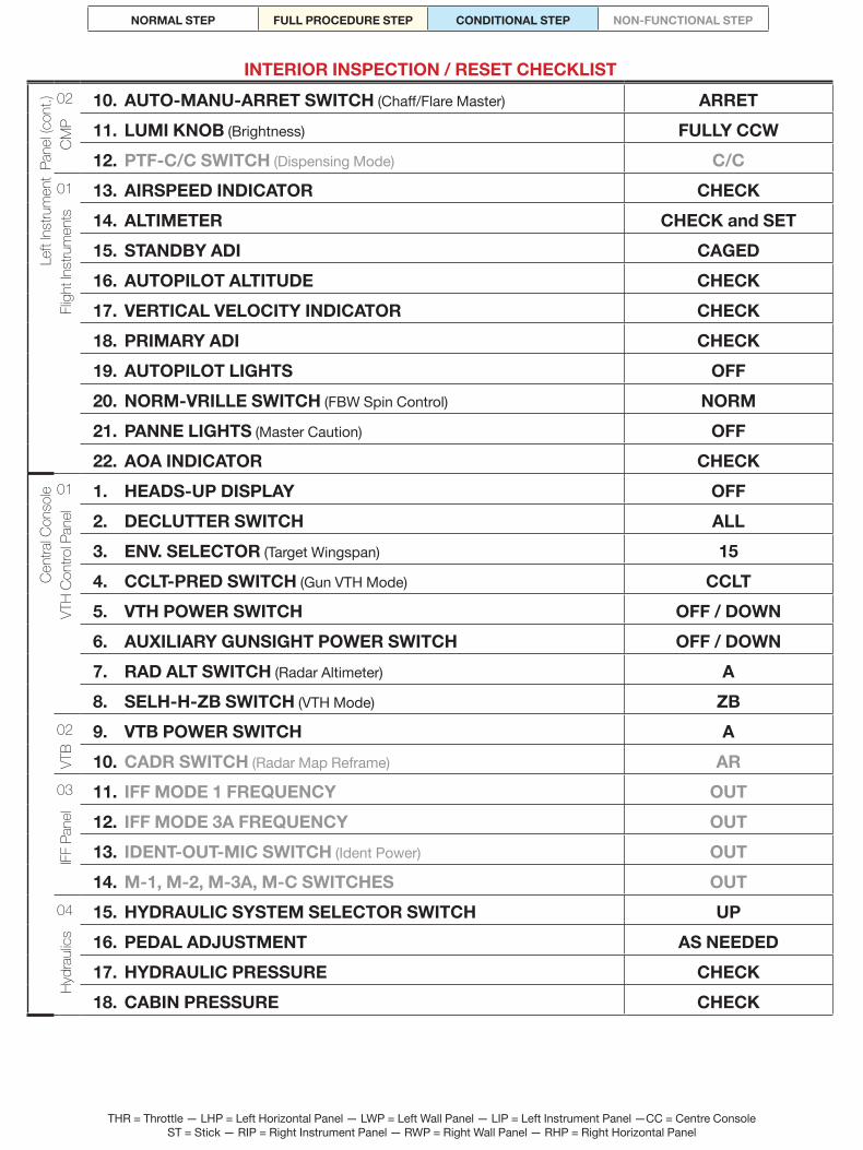
t.) 02 10. AUTO-MANU-ARRET SWITCH (Chaff/Flare Master) ARRET
CMP 11. LUMI KNOB (Brightness) FULLY CCW
12. PTF-C/C SWITCH (Dispensing Mode) C/C01 13. AIRSPEED INDICATOR CHECK
Fligh
t Inst
rum
ents 14. ALTIMETER CHECK and SET
15. STANDBY ADI CAGED16. AUTOPILOT ALTITUDE CHECK17. VERTICAL VELOCITY INDICATOR CHECK18. PRIMARY ADI CHECK19. AUTOPILOT LIGHTS OFF20. NORM-VRILLE SWITCH (FBW Spin Control) NORM21. PANNE LIGHTS (Master Caution) OFF22. AOA INDICATOR CHECK
Cent
ral C
onso
le 01 1. HEADS-UP DISPLAY OFF
VTH
Cont
rol P
anel 2. DECLUTTER SWITCH ALL
3. ENV. SELECTOR (Target Wingspan) 154. CCLT-PRED SWITCH (Gun VTH Mode) CCLT5. VTH POWER SWITCH OFF / DOWN6. AUXILIARY GUNSIGHT POWER SWITCH OFF / DOWN7. RAD ALT SWITCH (Radar Altimeter) A8. SELH-H-ZB SWITCH (VTH Mode) ZB
02 9. VTB POWER SWITCH A
VTB
10. CADR SWITCH (Radar Map Reframe) AR03 11. IFF MODE 1 FREQUENCY OUT
IFF P
anel 12. IFF MODE 3A FREQUENCY OUT
13. IDENT-OUT-MIC SWITCH (Ident Power) OUT14. M-1, M-2, M-3A, M-C SWITCHES OUT
04 15. HYDRAULIC SYSTEM SELECTOR SWITCH UP
Hydr
aulic
s 16. PEDAL ADJUSTMENT AS NEEDED17. HYDRAULIC PRESSURE CHECK18. CABIN PRESSURE CHECK
THR = Throttle — LHP = Left Horizontal Panel — LWP = Left Wall Panel — LIP = Left Instrument Panel —CC = Centre Console ST = Stick — RIP = Right Instrument Panel — RWP = Right Wall Panel — RHP = Right Horizontal Panel
NORMAL STEP FULL PROCEDURE STEP CONDITIONAL STEP NON-FUNCTIONAL STEP
INTERIOR INSPECTION / RESET CHECKLISTRi
ght In
stru
men
t Pan
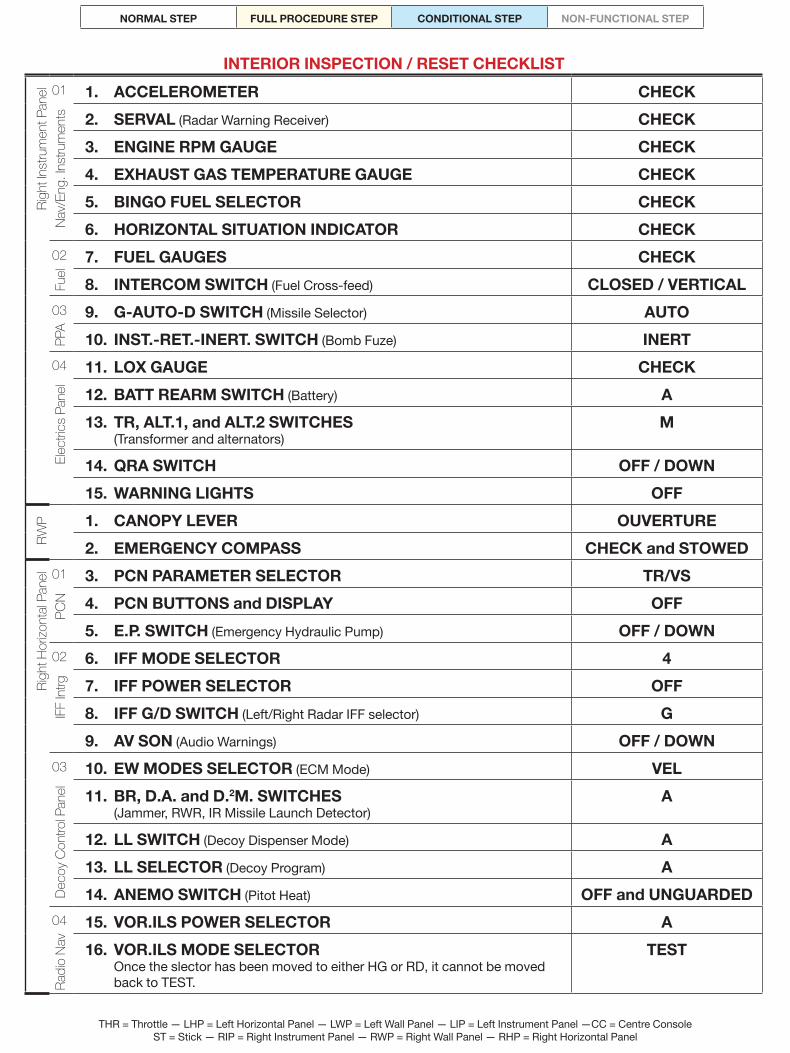
el 01 1. ACCELEROMETER CHECK
Nav/
Eng.
Inst
rum
ents 2. SERVAL (Radar Warning Receiver) CHECK
3. ENGINE RPM GAUGE CHECK4. EXHAUST GAS TEMPERATURE GAUGE CHECK5. BINGO FUEL SELECTOR CHECK6. HORIZONTAL SITUATION INDICATOR CHECK
02 7. FUEL GAUGES CHECK
Fuel
8. INTERCOM SWITCH (Fuel Cross-feed) CLOSED / VERTICAL03 9. G-AUTO-D SWITCH (Missile Selector) AUTO
PPA
10. INST.-RET.-INERT. SWITCH (Bomb Fuze) INERT04 11. LOX GAUGE CHECK
Elec
trics
Pane
l
12. BATT REARM SWITCH (Battery) A13. TR, ALT.1, and ALT.2 SWITCHES
(Transformer and alternators)M
14. QRA SWITCH OFF / DOWN15. WARNING LIGHTS OFF
RWP 1. CANOPY LEVER OUVERTURE
2. EMERGENCY COMPASS CHECK and STOWED
Righ
t Hor
izont
al Pa
nel 01 3. PCN PARAMETER SELECTOR TR/VS
PCN 4. PCN BUTTONS and DISPLAY OFF
5. E.P. SWITCH (Emergency Hydraulic Pump) OFF / DOWN02 6. IFF MODE SELECTOR 4
IFF In
trg 7. IFF POWER SELECTOR OFF8. IFF G/D SWITCH (Left/Right Radar IFF selector) G9. AV SON (Audio Warnings) OFF / DOWN
03 10. EW MODES SELECTOR (ECM Mode) VEL
Deco
y Con
trol P
anel 11. BR, D.A. and D.2M. SWITCHES
(Jammer, RWR, IR Missile Launch Detector)A
12. LL SWITCH (Decoy Dispenser Mode) A13. LL SELECTOR (Decoy Program) A14. ANEMO SWITCH (Pitot Heat) OFF and UNGUARDED
04 15. VOR.ILS POWER SELECTOR A
Radi
o Na
v
16. VOR.ILS MODE SELECTOR Once the slector has been moved to either HG or RD, it cannot be moved back to TEST.
TEST

THR = Throttle — LHP = Left Horizontal Panel — LWP = Left Wall Panel — LIP = Left Instrument Panel —CC = Centre Console ST = Stick — RIP = Right Instrument Panel — RWP = Right Wall Panel — RHP = Right Horizontal Panel
NORMAL STEP FULL PROCEDURE STEP CONDITIONAL STEP NON-FUNCTIONAL STEP
INTERIOR INSPECTION / RESET CHECKLISTRi
ght H
orizo
ntal
Pane
l (con
t.) 04 17. TACAN MODE SELECTOR OFF05 18. INS/PCN MODE SELECTOR AR
PSM 19. INS/PCN OPERATION MODE SELECTOR N
20. CAP SEC. SWITCH (Standby ADI) A06 21. EQUIP SWITCH (ECS Main Mode) AUT
Envir
onm
ent C
ontro
l
22. C and F BUTTONS (Avionics Hot and Cold Mode) OFF23. COND SWITCH (Air Conditioning) M24. DEPOLL CAB SWITCH (ECS Air Exchange) A25. ECS TEMPERATURE SELECT KNOB AUTO26. DESEMB SWITCH (Defogging) A
07 27. UV, PL DE BORD, BANQUETTES, VOYANTS NUIT/JOUR, BLANC KNOBS (Dashbord UV, Panel, Red Flood, Console Panel, Day/Night, and White Flood Light)
FULLY CCW
08 28. START BUTTON COVERED
Star
ter P
anel 29. POMPE SWITCH (Starter Fuel Pump) OFF / LEFT
30. POMPES BP G and D (Left and Right Fuel Pump) OFF / LEFT31. VENT-G-D SWITCH (Ignition/Ventilation Selector) D32. COUPE FEU SWITCH (Fuel Cutoff) OFF and UNGUARDED
09 33. ALL CIRCUIT BRAKERS IN34. PARKING BRAKE DISENGAGED / DOWN
END

THR = Throttle — LHP = Left Horizontal Panel — LWP = Left Wall Panel — LIP = Left Instrument Panel —CC = Centre Console ST = Stick — RIP = Right Instrument Panel — RWP = Right Wall Panel — RHP = Right Horizontal Panel
NORMAL STEP FULL PROCEDURE STEP CONDITIONAL STEP NON-FUNCTIONAL STEP
PREFLIGHT CHECKLISTLe
ft Ho
rizon
tal P
anel 10 1. CDVE 5 SWITCH OFF and GUARDED
09 2. TEST PA and CDVE SWITCHES OFF and GUARDED08 3. COUPURE P.C., SEC HIULE, and SEC CALC SWITCHES OFF and GUARDED
4. VIDE VITE BUTTON COVERED06 5. AUDIO VOLUMES CHECK and SET
6. R.ALL. VOL SWITCH OFF05 7. THROTTLE STOP
8. RADAR POWER KNOB A9. EMERGENCY THROTTLE COVERED
04 10. PELLES, SOURIS, and BECS SWITCHES AUTO03 11. EXTERNAL LIGHTS OFF
12. FREINS 1 and GUARDED02 13. V/UHF RADIO MODE SELECTOR PAL
14. M-P-G SELECTOR AS REQUIRED15. VHF FREQUENCY and CHANNEL AS REQUIRED
01 16. UFH RADIO MODE SELECTOR M17. UHF CHANNEL AS REQUIRED
LWP 1. CROSSE/PARACHUTE LEVER FULLY FORWARD
2. SECOURS FRAGIL. VERRIERE LEVER FULLY BACKWARD
Left
Instru
men
t Pan
el 04 1. LANDING GEAR LEVER DOWN and SECURED2. GAIN CDVE-NORM SWITCH NORM and GUARDED3. A/A-CHARGES SWITCH AS REQUIRED
03 4. ARME SWITCH OFF5. SEL SWITCH OFF and GUARDED
01 6. STANDBY ADI UNCAGED7. NORM-VRILLE SWITCH NORM
Cent
ral C
onso
le 01 1. VTH POWER SWITCH ON2. RADAR ALTIMETER AS DESIRED
02 3. VTB POWER SWITCH M03 4. IDENT-OUT-MIC SWITCH OUT
5. M-3A and M-C SWITCHES ON
RIP 01 1. HORIZONTAL SITUATION INDICATOR Cm NAV or Cv NAV
2. BINGO FUEL SELECTOR SET

THR = Throttle — LHP = Left Horizontal Panel — LWP = Left Wall Panel — LIP = Left Instrument Panel —CC = Centre Console ST = Stick — RIP = Right Instrument Panel — RWP = Right Wall Panel — RHP = Right Horizontal Panel
NORMAL STEP FULL PROCEDURE STEP CONDITIONAL STEP NON-FUNCTIONAL STEP
PREFLIGHT CHECKLISTRI
P 02 3. INTERCOM SWITCH CLOSED / VERTICAL04 4. QRA SWITCH OFF / DOWN
Righ
t Hor
izont
al Pa
nel 01 1. E.P. SWITCH AUTO / MIDDLE
02 2. AV SON OFF / DOWN04 3. VOR.ILS POWER SELECTOR A
4. TACAN MODE SELECTOR OFF05 5. INS MODE SELECTOR AR
6. CAP SEC. SWITCH M08 7. PUMP SWITCHES OFF
8. POMPE SWITCH OFF / LEFT9. VENT-G-D SWITCH D10. COUPE FEU SWITCH OFF and UNGUARDED
09 11. ALL CIRCUIT BREAKERS INEND
BEFORE ENGINE START CHECKLIST
Righ
t Inst
rum
ent P
anel 04 1. BATT SWITCH ON
TR, ALT.1, ALT.2, HUILE, B.P., BP.G, BP.D, HYD.1, HYD.2, E.P., P.CAB, ANEMO, DECOL lights illuminate. If HYD.S light illuminates instead of E.P. light, the E.P. switch is in the OFF (down) position rather than AUTO (middle).
2. TRN, ALT.1 and ALT.2 SWITCHES ON3. EXTERNAL POWER SUPPLY CONNECTED
If requiredTR light goes out.
NOTE To expedite the lengthy INS alignment process and allow an early RDI warm-up, external power should be applied as early in the start-up
process as possible. This will allow the on-board systems to be set up and manipulated without unduly draining battery power or burning fuel to power the engine generators.
If multiple ground procedures are to be run through, the order of priority should be 1) ground power connected, 2) rearming and refuelling, 3) ground maintenance.
4. WARNING LIGHTS TEST SWITCH Switch should return to middle position when released.
1, then 2
Righ
t Hor
iz. P
an. 01 1. E.P. SWITCH
Switch should return to AUTO (middle) position when released.TEST / UP
05 2. INS ALIGN06 3. ENVIRONMENTAL CONTROLS AS DESIRED07 4. INTERNAL LIGHTS AS DESIRED
LHP 03 5. ANTI COLL SWITCH FAB or FORT
As required
END

THR = Throttle — LHP = Left Horizontal Panel — LWP = Left Wall Panel — LIP = Left Instrument Panel —CC = Centre Console ST = Stick — RIP = Right Instrument Panel — RWP = Right Wall Panel — RHP = Right Horizontal Panel
NORMAL STEP FULL PROCEDURE STEP CONDITIONAL STEP NON-FUNCTIONAL STEP
INS ALIGNMENT CHECKLISTRi
ght H
orizo
ntal
Pane
l 05 1. PCN OPERATIONAL MODE SELECTOR N2. INS/PCN MODE SELECTOR VEI
01 PREP Waypoint 00 is automatically selected on the PCN.
NOTE To Perform a Standard Alignment, follow steps 3–4, then proceed to step 6.
Standard Alignment is required when you start from the ramp or you have requested aircraft repairs from the ground crew.
3. INITIAL POSITION CHECK and SET• PCN Parameter Selector to L/G.• Press +/1 or -/7 to edit latitude. Use N/2 and S/8 to indicate northern or southern latitude, followed by 6 digits, confirm with INS button. Press +/3 or -/9 to edit longitude. Use W/4 and E/6 to indicate western or eastern longitude, followed by 7 digits. Confirm with INS button.
• PCN Parameter Selector to ALT.• Press +/1 or -/7 to edit altitude in feet, or +/3 or -/9 to edit altitude in meters. Begin with + or - to indicate positive or negative altitude, followed by 4 digits, confirm with INS button. Only one entry is needed – the other will update to match.
NOTE Refer to the kneeboard for initial position data.
05 4. INS/PCN MODE SELECTOR ALNNOTE
To perform a Memory Alignment, follow step 5, then proceed to step 6. Memory Alignment is required when you have requested a rearm/refuel from the ground crew.
5. INS/PCN MODE SELECTOR ALCM01 The ALN yellow light will blink; the VAL button will illuminate.
6. VAL BUTTON PRESSThe ALN yellow light will become steady, indicating that the INS is aligning; the VAL button will extinguish. At this point you can edit the waypoint data. The alignment process will abort if you click the INS/PCN Mode knob to another position or if you try to edit the Waypoint 00 data.
The ALN yellow light will turn off when the first coarse alignment (Class 4) has been reached. At the same time the PRET green light will start blinking. At this stage it is safe to abort the alignment process, the INS will remain aligned but its precision will be very low.
You can check the alignment process by clicking the PCN Operational Mode knob to STS.
7. PRET GREEN LIGHT STEADY When alignment complete.
8. PCN PARAMETER SELECTOR TR/VSNOTE
While taxiing, the INS/PCN ground speed indicator will be a better guide for safe speeds than the HUD or main instrument panel IAS gauge since both have minimum-speed thresholds and are affected by wind conditions. As such, they may indicate unsafe taxiing conditions as
safe and vice versa.
05 9. INS/PCN MODE SELECTOR NAV10. PCN OPERATIONAL MODE SELECTOR N
END

THR = Throttle — LHP = Left Horizontal Panel — LWP = Left Wall Panel — LIP = Left Instrument Panel —CC = Centre Console ST = Stick — RIP = Right Instrument Panel — RWP = Right Wall Panel — RHP = Right Horizontal Panel
NORMAL STEP FULL PROCEDURE STEP CONDITIONAL STEP NON-FUNCTIONAL STEP
ENGINE START CHECKLISTRH
P 09 1. PARKING BRAKE SETPARK light illuminates.
LIP 01 1. PANNE LIGHT PRESS
Righ
t Hor
izont
al Pa
nel 02 1. AV SON ON
08 2. COUPE FEU SWITCH ON and GUARDED3. POMPES BP G and D M4. VENT-G-D SWITCH D or G AS REQUIRED5. POMPE SWITCH ON6. START BUTTON UNCOVERED7. B.P. WARNING LIGHT CHECK OFF8. START BUTTON PRESS
Righ
t Inst
rum
ent P
anel 01 1. ENGINE RPM SPOOLS UP TO 10%
01 & 04
2. THROTTLE JUST PAST IDLE3. RPM and Tt7 GAUGES, WARNING LIGHTS
- HUILE, T7 warning lights - RPM - Exhaust Gas Temperature - Fuel Flow - HYD.S warning light - HYD.2, EP caution lights - TR, ALT.1, ALT.2 caution lights - HYD.1, BP.G, BP.D caution lights - PCA and PPA - Landing Gear Panel
MONITOR Out as engine starts
Steady climb to ~60% RPM Steady climb to <550°C
Steady climb to ~17 kg/min Out at ~20% RPM Out at ~25% RPM
Out at 40–45% RPM Out as transformer starts On as transformer starts
On as HYD.1 starts
NOTE If ground power is connceted, ALT.1 and ALT.2 caution lights will remain illuminated to indicate that the on-board alternators are not running.
The lights will go out as ground power is disconnected.
4. THROTTLE - RPM - Tt7 - Fuel Flow
IDLE 49%
~450°C 16 kg/min
5. REMAINING WARNING LIGHTS The following lights should or may still be on: - ALT.1 and ALT.2 - P.CAB - ANEMO - DECOL - PARK The lights will go out as post-start procedures are performed.
CHECK Reason:
If ground power is on Canopy open
Pitot heating off No FBW test, other warnings
Parking brake on
RHP 08 1. START BUTTON COVERED
2. POMPE SWITCH OFF3. VENT-G-D SWITCH VENT
END

THR = Throttle — LHP = Left Horizontal Panel — LWP = Left Wall Panel — LIP = Left Instrument Panel —CC = Centre Console ST = Stick — RIP = Right Instrument Panel — RWP = Right Wall Panel — RHP = Right Horizontal Panel
NORMAL STEP FULL PROCEDURE STEP CONDITIONAL STEP NON-FUNCTIONAL STEP
AFTER ENGINE START CHECKLISTLe
ft Ho
rizon
tal P
anel 02 1. POLICE LIGHT SWITCH ON
2. PHARES-A.ROUL.-ATT SWITCH A.ROUL.03 3. FEUX NAV, and FEUX FORMAT FAB or FORT
As required
05 4. RADAR POWER KNOB P.CHNOTE
The RDI needs a 2-minute warm up period before it is fully functional. While heating up, a blinking P will be displayed on the VTB. When the P becomes steady, the Radar Power Knob can be moved to SIL.
5. PPI-B SWITCH AS DESIRED09 6. CDVE TEST
Open the cover on the TEST CDVE switch and move it to the L position. Wait for the test to complete with a green light. Move the switch to the C position. Wait for the test to complete with a green light. Return the switch to the centre position and close the cover.
Completed tests are a requirement for the DECOL warning light to go out.
ѥ WARNING If the fly-by-wire self tests do not return a green result, the FBW system is degraded and take-off should be aborted pending testing
inspection and maintenance.
7. PA TESTOpen the cover on the TEST PA switch and move it to the M position. This will trigger the PA warning light and alert sound. Wait until the test completes with a green light. Move the switch back to the A position and close the cover.
A completed test is a requirement for the DECOL warning light to go out.
Ћ CAUTION If the autopilot self test does not return a green result, the AP system is degraded and all
flight will have to be done manually, pending inspection and maintenance.
Left
Instru
men
t 01 1. AUTOPILOT ALTITUDE SET2. BAROMETRIC ALTIMETER SET3. STANDBY ADI UNCAGED and SET
02 4. AUTO-MANU-ARRET SWITCH MANU03 5. PCA STORES and MODES CHECK
Righ
t Inst
r. 03 1. PPA TEST-PRES SWITCH Switch should return to middle position when released.
TEST
01 2. HSI SET3. SERVAL CHECK
RHP 04 1. VOR.ILS POWER SELECTOR M
2. VOR.ILS FREQUENCY SET3. TACAN MODE SELECTOR T/R4. TACAN CHANNEL SET

THR = Throttle — LHP = Left Horizontal Panel — LWP = Left Wall Panel — LIP = Left Instrument Panel —CC = Centre Console ST = Stick — RIP = Right Instrument Panel — RWP = Right Wall Panel — RHP = Right Horizontal Panel
NORMAL STEP FULL PROCEDURE STEP CONDITIONAL STEP NON-FUNCTIONAL STEP
AFTER ENGINE START CHECKLISTRi
ght H
orizo
ntal
Pane
l (con
t.) 03 5. EW MODES SELECTOR □
6. BR, D.A., and D.2M. SWITCHES T, then M7. L.L. MODE SWITCH S.A.8. L.L. PROGRAM SELECTOR AS REQUIREDProgram Name Chaff Flare Interval Cycles Cyc. Interval
1 BVR 1 6 0.50 12 BVR 2 6 0.50 2 2.003 BVR 3 6 0.50 3 2.004 CCM 1 1 15 CCM 2 1 1 16 SAM 1 12 0.75 17 SAM 2 20 0.25 18 IR SAM 6 0.25 19 AG Mix 20 6 0.25 110 Flare Jettison 32 0.05 1
02 9. IFF POWER SELECTOR SECT
Cent
re C
onso
le 01 1. VTH POWER SWITCH ON2. RAD ALT SWITCH TEST, then M3. MINIMUM ALTITUDE SETZB-H-SELH switch to SELH. Turn Rad Alt knob to set the minimum/abort altitude.
4. ZB-H-SELH SWITCH AS DESIRED02 5. VTB POWER SWITCH M04 6. HYDRAULIC PRESSURE CHECK
Change the Hydraulic System Selector switch from System 1 (up) to System 2 (down) and observe the Sdes gauge — it should read 280 PSI for both systems. With the handbrake engage, the Fs gauge should read 10 for both systems.
Cock
pit 1. RUDDER DEFLECTION CHECK
2. FLIGHT CONTROLS SURFACES CHECK3. AIRBRAKES and SLATS CHECK
To test the wing slats click the BECS switch to OUT. The slats should actuate out. Click the switch back to AUTO. The slats should return to its stowed position. This will trigger the BECS caution light and sound.
4. PANNE BUTTON PRESS To cancel testing alerts.
END

THR = Throttle — LHP = Left Horizontal Panel — LWP = Left Wall Panel — LIP = Left Instrument Panel —CC = Centre Console ST = Stick — RIP = Right Instrument Panel — RWP = Right Wall Panel — RHP = Right Horizontal Panel
NORMAL STEP FULL PROCEDURE STEP CONDITIONAL STEP NON-FUNCTIONAL STEP
TAXI CHECKLISTRi
ght H
orizo
ntal
Pane
l 05 1. INS/PCN MODE SELECTOR When INS alignment is complete and the green PRET light is stead on the PCN.
NAV
Ћ CAUTION Wait until alignment is complete before taxiing. Moving the aircraft while the INS is still
aligning will result in degraded performance and precision of the INS/PCN,
2. PCN OPERATIONAL MODE SELECTOR N03 3. ANEMO SWITCH ON and GUARDED
ANEMO caution light and DECOL warning light extinguish.
4. TAXI CLEARANCE REQUESTED5. GROUND POWER DISCONNECTEDALT.1 and ALT.2 caution lights extinguish.
08 6. HANDBRAKE OFFPARK caution light extinguishes.
Fligh
t con
trols
and
instru
men
ts 1. WHEEL BRAKES PRESS and RELEASEUnder certain conditions, the FREIN light may still be on after the handbrake is released. Pump the wheel brakes to actuate the brakes and make the FREIN light extinguish.
2. CANOPY CLOSED and LOCKEDP CAB caution light extinguishes.
3. TAKE-OFF CONFIGURATION - P CAB warning light - CONF caution light - DECOL warning light - PARK caution light
CHECK Off Off Off Off
The CONF caution light will not go out if the FBW G-limiter switch position does not match the stores carried:• A/A (up) — only Magic II and/or Super S530D are carried, or a clean aircraft.• Charges (down) — any other stores are carried.
The DECOL warning light will not go out if:• The slats are not in the AUTO position (indicated by the BECS caution light).• The ANEMO switch is not in the on position (indicated by the ANEMO caution light).• The FBW Gain Mode switch is not in the NORM position (indicated by the DSV warning light).• The CDVE 5 switch is not in the forward and guarded position.• The PA and CDVE tests have not been completed with green lights and the covers are closed.• The aircraft is not trimmed neutral (press Autopilot standby to reset trim).
4. NOSEWHEEL STEERING ENGAGE5. THROTTLE
To start rolling — the exact RPM depends on loadout.FORWARD To ~65% RPM
NOTE If properly aligned and calibrated, the TR/VS mode on the PCM provides accurate ground-speed readings even at low speed.
Ћ CAUTION Do not exceed 40 kts while taxiing, as nosewheel steering will disengage automatically, which may cause a sudden loss
of control. Avoid making sharp turns above 20 kts. If the canopy is left open during taxi, do not exceed 20 kts.
END

THR = Throttle — LHP = Left Horizontal Panel — LWP = Left Wall Panel — LIP = Left Instrument Panel —CC = Centre Console ST = Stick — RIP = Right Instrument Panel — RWP = Right Wall Panel — RHP = Right Horizontal Panel
NORMAL STEP FULL PROCEDURE STEP CONDITIONAL STEP NON-FUNCTIONAL STEP
TAKE-OFF CHECKLIST1. TAKEOFF REQUESTED2. RUNWAY LINED UP3. RADAR POWER KNOB
If warmed up and the VTB does not show a blinking P.SIL
4. NOSEWHEEL STEERING DISENGAGE5. HYDRAULICS ADVISORY LIGHTS ALL OFF6. CAUTION/WARNING LIGHTS ALL OFF7. FULL THROTTLE INTO MAX AFTERBURNER CHECK ACCEL.
(Jx) IN HUD8. PC ADVISORY LIGHT ON9. ROTATE AT 120 KNOTS.
Place horizon on the rotation pitch marker in the HUD
10. LANDING GEAR RETRACT and STOW Before 260 knots.
11. ANTI COLL. LIGHT SWITCH OFFEND
ENGINE AIR RESTART CHECKLIST1. AIRCRAFT PITCH DOWN2. THROTTLE IDLE3. ENGINE SHUTDOWN BUTTON PRESS4. POMPE SWITCH ON5. RALL VOL SWITCH ON6. THROTTLE FORWARD
Until RPM >50%
7. RALL VOL SWITCH OFF8. POMPE SWITCH OFF
END

THR = Throttle — LHP = Left Horizontal Panel — LWP = Left Wall Panel — LIP = Left Instrument Panel —CC = Centre Console ST = Stick — RIP = Right Instrument Panel — RWP = Right Wall Panel — RHP = Right Horizontal Panel
NORMAL STEP FULL PROCEDURE STEP CONDITIONAL STEP NON-FUNCTIONAL STEP
BEFORE LANDING CHECKLISTLe
ft Ins
trum
ent P
anel 03 1. ARME SWITCH OFF
2. SEL SWITCH OFF and GUARDED3. PCA MODE APP4. HOTAS SPECIAL MODES BUTTON PRESS
04 5. HYDRAULICS ADVISORY LIGHTS CHECK6. A/A-CHARGES SWITCH AS REQUIRED
NOTE Setting the FBW Mode switch to CHARGES dampens out stick input, allowing for more precise controls during approach and landing.
However, if only A/A stores are carried, this will trigger a CONF caution light and sound notice.
LHP 02 1. PHARES-A.ROUL.-ATT SWITCH ATT
03 2. EXTERNAL LIGHTS AS REQUIRED3. SPAD SWITCH ON and GUARDED
05 4. RADAR POWER KNOB SIL
Righ
t Hor
izont
al Pa
nel 04 1. VOR/ILS FREQUENCY SET
2. VOR/ILS POWER KNOB M3. TACAN CHANNEL SET4. TACAN MODE KNOB T/R
01 5. INS/PCN DESTINATION SETIf using the INS/PCN to guide to the runway, the BAD (offet) mode can be used to guide to a glideslope capture point. Turn the PCN Parameter Selector to ∆ALT and enter 3000' / 914m. Turn the selector to Ρ/Θ and enter the distance 10.00nm on the left and the inverse of desired runway heading on the right (e.g. if landing on a runway heading 087°, enter θ value 267). The BAD button in the PCN panel can be used to switch between navigation point and offset for navigation via the HSI.
NOTE If using preloaded WP data, selecting a designated landing WP on the PCN lets the HUD to display a synthetic runway in APP mode.
Righ
t Inst
rum
ent P
anel 01 1. HSI SET
If using a TACAN or VOR beacon to guide to the runway, the HSI TAC and VAD (offset) modes can be used to guide to a glideslope capture point. Select ρ mode and enter 10nm as the distance; select .θ mode and enter the inverse of the desired runway heading (e.g. if landing on a runway heading 087°, enter θ value 267). Select VAD mode to guide towards a capture point 10nm out at 3000' AGL. As the distance to the offset point reaches <2nm, switch to TAC mode to guide towards the TACAN or VOR beacon, or approach the runway using VFR from this point.
NOTE All radio navigation modes on the HSI use magnetic headings. If navigating using the INS/PCN, magnetic or true headings are displayed depending on whether the HSI is in NAV Cv (true) or NAV Cm (magnetic) mode, but all PCN inputs should be true headings. Ensure that
correct values are used when entering desired course and heading data.
1. HUD CHECK2. DECISION HEIGHT SET
Set the ZB-H-SELH switch to SELH. Use the RAD ALT knob to select an AGL altitude as the approach decision height.
3. ZB-H-SELH SWITCH H4. TEST-M-A SWITCH M5. LANDING CLEARANCE REQUESTED
END

THR = Throttle — LHP = Left Horizontal Panel — LWP = Left Wall Panel — LIP = Left Instrument Panel —CC = Centre Console ST = Stick — RIP = Right Instrument Panel — RWP = Right Wall Panel — RHP = Right Horizontal Panel
NORMAL STEP FULL PROCEDURE STEP CONDITIONAL STEP NON-FUNCTIONAL STEP
VFR LANDING CHECKLIST1. LANDING GEAR DOWN BELOW 260 KTS2. LANDING GEAR WARNING LIGHTS GREEN3. SPAD SWITCH CHECK4. HUD FLIGHT PATH MARKER ON RWY, IN BRACKETS5. HUD ACCELERATOR CHEVRONS IN BRACKETS
NOTE Use rudder inputs to correct left/right deviation from runway centreline. Avod rolling since it changes lift vectors and will also affect the speed and descent rate. Use throttle to adjust vertical velocity: if the flight path marker is short of runway, increase throttle; if the flight path marker is long, decrease throttle. Try to maintain a 7–800 ft/min VVI (300 ft/nm) depending on ground speed. Use pitch to adjust speed and angle of
attack — maintain a 14° α during descent at any given throttle setting. The HUD landing speed brackets offer a visual aid for the right balance between pitch and throttle.
6. AoA (α) ON FINAL APPROACH 14°7. WHEEL BRAKES ON BELOW 140 KNOTS
Whenever possible, release controls stick to allow the FBW to maintain a 14° AoA while rolling down the runway. This allows the delta wing to act as an airbrake, and allows wheel brakes to only be used below 100 kts to reduce wear and tear.
8. NWS ON BELOW 40 KNOTSEND
IFR/ILS LANDING CHECKLIST1. LANDING GEAR DOWN BELOW 260 KTS2. LANDING GEAR WARNING LIGHTS GREEN3. SPAD SWITCH CHECK4. PRIMARY ADI FOLLOW ILS NEEDLES5. HUD FLIGHT PATH MARKER IN ILS GUIDE BOX
NOTE Use rudder inputs to correct left/right deviation. Rolling changes lift vectors and will also affect speed and descent rate Use throttle to adjust vertical velocity: if below the needle, increase throttle; if above, decrease it. Use pitch to adjust speed and angle of attack — maintain a 14° α
during descent.
6. HSI CHECK HEADING7. VERTICAL VELOCITY INDICATOR ~7–800 FT/MIN
Depending on ground speed.
8. HUD ACCELERATOR CHEVRONS IN BRACKETS9. HUD FLIGHT PATH MARKER ON SYNTHETIC RWY
If available
10. AoA (α) ON FINAL APPROACH 14°11. WHEEL BRAKES ON BELOW 140 KNOTS
Whenever possible, release controls stick to allow the FBW to maintain a 14° AoA while rolling down the runway. This allows the delta wing to act as an airbrake, and allows wheel brakes to only be used below 100 kts to reduce wear and tear.
12. NWS ON BELOW 40 KNOTSEND

THR = Throttle — LHP = Left Horizontal Panel — LWP = Left Wall Panel — LIP = Left Instrument Panel —CC = Centre Console ST = Stick — RIP = Right Instrument Panel — RWP = Right Wall Panel — RHP = Right Horizontal Panel
NORMAL STEP FULL PROCEDURE STEP CONDITIONAL STEP NON-FUNCTIONAL STEP
AUTOPILOT LANDING CHECKLIST1. LANDING GEAR DOWN BELOW 260 KTS2. LANDING GEAR WARNING LIGHTS GREEN3. SPAD SWITCH CHECK4. AUTPILOT APPROACH MODE ON
NOTE The approach mode will go green and engage when an ILS glideslope has been captured and will apply stick input to attempt to follow the
glideslope.
Ћ CAUTION The autopilot will disengage if ILS signal is lost or if the aircraft flies too far outside of the indicated glideslope, which
may happen as result of the autpilot manoeuvring if starting too far offset or off angle from the glideslope.
ѥ WARNING The autopilot actuates stick movement only. The pilot has to maintain throttle to ensure correct descent rate and AoA. Maintain regular
VFR or IFR observations to ensure that the autopilot keeps the aircrat within acceptable landing parameters.
5. HUD FLIGHT PATH MARKER ON RWY6. HUD ACCELERATOR CHEVRONS IN BRACKETS
Ћ CAUTION The HUD landing speed brackets offer a visual aid for the correct balance between throttle and pitch, but can vary significantly as the
autopilot adjusts pitch and will also change as wind gusts influence the AoA meter.
Take care not to chase the chevrons and overcompensate throttle input — look to maintain a steady descent rate.
7. AoA (α) ON FINAL APPROACH 14°8. AUTOPILOT DISENGAGE
On touch-down.
9. WHEEL BRAKES ON Below 140 knots
Whenever possible, release controls stick to allow the FBW to maintain a 14° AoA while rolling down the runway. This allows the delta wing to act as an airbrake, and allows wheel brakes to only be used below 100 kts to reduce wear and tear.
10. NWS ON Below 40 knots
END
RUNWAY VACATED CHECKLIST1. LANDING LIGHTS TAXI2. ANTI COLL LIGHTS ON3. IFF OFF4. VOR/ILS A5. TACAN OFF
END

THR = Throttle — LHP = Left Horizontal Panel — LWP = Left Wall Panel — LIP = Left Instrument Panel —CC = Centre Console ST = Stick — RIP = Right Instrument Panel — RWP = Right Wall Panel — RHP = Right Horizontal Panel
NORMAL STEP FULL PROCEDURE STEP CONDITIONAL STEP NON-FUNCTIONAL STEP
PARKING CHECKLISTRI
HP
01 1. THROTTLE IDLE09 2. HANDBRAKE ON02 3. AV SON SWITCH OFF03 4. ANEMO SWITCH UNGUARDED and OFF
5. EXTERNAL POWER SUPPLY CONNECTEDNOTE
Unless supported by ground power, equipment on the AC and DC buses will disengage automatically from power loss as the engine and battery is shut down, respectively. To avoid power spikes and potential system damage, they should be shut down manually whenever
possible.
6. CANOPY OPEN
CC
01 7. VTH OFF8. TEST-M-A SWITCH A
02 9. VTB POWER SWITCH A
LIP
01 1. AUTOPILOT OFF2. STANDBY ADI CAGED
LHP 01 1. U/VHF and UHF MODE SWITCHES AR
05 2. RADAR POWER KNOB A3. ENGINE SHUTDOWN BUTTON PRESS
Once Tt7 <500°C
Righ
t Hor
izont
al Pa
nel 08 4. POMPES BP, G and D SWITCHES OFF
Once engine stopped.
5. COUPE FEU SWITCH UNGUARDED and OFF07 6. INTERIOR LIGHTS AS REQUIRED06 7. ENVIRONMENTAL CONTROL AS REQUIRED05 8. INS/PCN MODE SELECTOR AR
NOTE If parking for a hot reload/refuel, there is an advantage in leaving the PCN on under ground power in order to make use of the abbreviated INS
memory alignment procedure in preparation for the next take-off.
9. CAP SEC. SWITCH A03 10. EW MODES SELECTOR VEL
11. BR, D.A. and D.2M. SWITCHES A12. LL SWITCH A
01 13. EP SWITCH OFF (DOWN)RIP 04 14. BATT and TR SWITCHES A
END

THR = Throttle — LHP = Left Horizontal Panel — LWP = Left Wall Panel — LIP = Left Instrument Panel —CC = Centre Console ST = Stick — RIP = Right Instrument Panel — RWP = Right Wall Panel — RHP = Right Horizontal Panel
NORMAL STEP FULL PROCEDURE STEP CONDITIONAL STEP NON-FUNCTIONAL STEP
INS POSITION UPDATE CHECKLISTSe
tup 1. LANDMARK POSITION ENTERED AS
DESTINATION2. LANDMARK DESTINATION FLY TOWARDS3. INS NAVIGATION CUES DISREGARD WHEN IN
VISUAL RANGE4. UPDATE METHOD
Use either a Fly-by or a Radar Ranging method to feed INS with updated position data through PCN.
SELECTED
Fly-b
y up
date 1. LANDMARK FLY DIRECTLY OVER
2. INS/PCN REC BUTTON PRESS Once over the landmark
Rada
r ran
ging
upda
te Ћ CAUTION Once started, waypoint Radar Ranging Position Update will be cancelled if: 1) you click Master ARM to the ON
position, 2) you click the radar to POL mode, 3) you click the PCA to APP mode, or 4) you select a weapon.
1. PCA MODE ARME switch off, no other mode selected.
NAV
2. OBL BUTTON PRESSThe radar will enter TAS mode and a diamond shaped radar cue will appear in the HUD. This cue represents the exact spot where the radar beam is pointing
3. HUD CUE and LANDMARK FLY TO ALIGN4. HOTAS TAS RANGING BUTTON PRESS
Acce
pt/re
ject u
pdat
e da
ta 1. VAL BUTTON ILLUMINATED If position difference <15nm
NOTE If the difference between aircraft and landmark position is too great, the VAL buton will remain off and the REC button will blink, indicating
that the update cannot be accepted. Press the REC button to cancel the attempt.
2. PCN VALUES REVIEW3. VAL BUTTON TO ACCEPT or
REC BUTTON TO REJECT PRESS
If accepted, the accumulated gyro drift will be reset to 0 and the aircraft present position will be corrected. Both REC and VAL buttons will go dark. If rejected, the INS will not update its position and will continue using the values it already has, including the accumulated drift error.
4. RADAR If using Radar Ranging update process.
RETURN TO NORMAL
END

THR = Throttle — LHP = Left Horizontal Panel — LWP = Left Wall Panel — LIP = Left Instrument Panel —CC = Centre Console ST = Stick — RIP = Right Instrument Panel — RWP = Right Wall Panel — RHP = Right Horizontal Panel
NORMAL STEP FULL PROCEDURE STEP CONDITIONAL STEP NON-FUNCTIONAL STEP
INS NAVIGATION CHECKLISTRi
ght H
orizo
ntal
Pane
l 05 1. INS/PCN OPERATIONAL MODE SELECTOR N2. INS/PCN MODE SELECTOR NAV
01 3. PCN DESTINATION SET and SELECTEDTo create a waypoint:
• Press PCN PREP button followed by a waypoint number (01–20).• PCN Parameter Selector to L/G.• Press +/1 or -/7 to edit latitude. Use N/2 and S/8 to indicate northern or southern latitude, followed by 6 digits, confirm with INS button. Press
+/3 or -/9 to edit longitude. Use W/4 and E/6 to indicate western or eastern longitude, followed by 7 digits. Confirm with INS button.Optionally, enter a waypoint altitude:
• PCN Parameter Selector to ALT.• Press +/1 or -/7 to edit altitude in feet, or +/3 or -/9 to edit altitude in meters. Begin with + or - to indicate positive or negative altitude,
followed by 4 digits, confirm with INS button. Only one entry is needed – the other will update to match. The altitude is relative to the zero (QFE or QNH) as set by the barometric altimeter.
Optionally, enter a desired bearing and time on waypoint:• PCN Parameter Selector to RD/TD.• Press +/1 or -/7 to edit desired bearing in degrees. Press +/3 or -/9 to enter desired chronometer time on waypoint. Begin with + or - to
indicate time relative to the current INS clock.If the waypoint is an airport, optionally enter runway heading and glideslope:
• PCN Parameter Selector to CP/PD.• Press +/1 or -/7 to edit the runway heading in degrees. Press +/3 or -/9 to enter the desired glideslope angle (e.g. 2.8 for a 300ft/nm descent).
To create a waypoint (Bearing, Altitude, Distance) offset (e.g for a target IP waypoint or for bullseye navigation):• PCN Parameter Selector to Ρ/Θ.• Press +/1 or -/7 to edit offset distance in nautical miles. Press +3/ or -/9 to edit offset azimuth in degrees. Note the HSI mode will determine
whether true or magnetic heading will be displayed, wheras the PCN only uses true headings as input — ensure that the correct heading is entered.
• Or PCN Parameter Selector to ∆L/∆G.• Press +/1 or -/7 to edit latitude offset in km. Use N/2 and S/8 to indicate whether the offset is to the north or the south. Press +/3 or -/9 to edit
longitude offset in km. Use W/4 and E/6 to indicate whether the offset is to the east or the west.Optionally, enter an offset altitude:
• PCN Parameter Selector to ∆ALT.• Press +/1 or -/7 to edit altitude in feet, or +/3 or -/9 to edit altitude in meters. Begin with + or - to indicate positive or negative altitude,
followed by 4 digits, confirm with INS button. Only one entry is needed – the other will update to match. The altitude will be relative to the waypoint altitude.
To select a waypoint:• Press PCN DEST button followed by a prepared waypoint number (01-20). If the selected waypoint does not exist, the destination will default
to DEST 01.
4. BAD BUTTON Turn on to navigate to a desitnation offset. Offset navigation is indicated on the HUD with an asterisk next to waypoint number.
AS REQUIRED
5. PCN PAREMETER SELECTOR D/RLT
HUD,
RIP 1. HSI MODE Cv NAV or Cm NAV
2. HUD, PCN, and HSI CUES HUD cues only show up in NAV mode. PCN cues only show up when D/RLT parameters are selected.
FOLLOW
END

THR = Throttle — LHP = Left Horizontal Panel — LWP = Left Wall Panel — LIP = Left Instrument Panel —CC = Centre Console ST = Stick — RIP = Right Instrument Panel — RWP = Right Wall Panel — RHP = Right Horizontal Panel
NORMAL STEP FULL PROCEDURE STEP CONDITIONAL STEP NON-FUNCTIONAL STEP
TACAN/VOR NAVIGATION CHECKLISTRi
ght H
orizo
ntal
Pane
l 04 1. VOR/ILS FREQUENCY SET2. VOR/ILS POWER KNOB
HSI Needle 2 flag hidden if beacon is detected.M
NOTE If an active station is selected, the VOR needle will indicate the bearing even in Cm and Cv NAV mode. The bearing displayed by the needle
will be true or magnetic depending on the mode selected.
3. TACAN CHANNEL SET4. TACAN MODE KNOB
HSI Needle 1 flag hidden if beacon is detected.T/R or A/A
T/R is used to track land-based beacons. A/A is used to track aerial beacons, such as those used by refuelling aircraft.
Righ
t Inst
rum
ent P
anel 01 1. HSI MODE KNOB TAC or VAD
VAD mode is used to create an offset point to a TACAN station:• Turn HSI Mode knob to ρ. Use Input knob to enter the offset distance from the TACAN station.• Turn HSI Mode knob to θ. Use input knob to enter the offset magnetic bearing from the TACAN station.• Turn HSI Mode knob to VAD to display distance and bearing to fly to the offset point.
NOTE Both TAC and VAD modes use magnetic headings. Ensure that a corrected bearing is used when using VAD mode.
2. NEEDLE 1 (WIDE) TACAN/VAD BEARING3. NEEDLE 2 (THIN) VOR BEARING4. DME DISPLAY TACAN/VAD DISTANCE
END
AUTOPILOT NAVIGATION CHECKLIST
Left
Instru
men
t Pan
el 01 1. AUTOPILOT ON 2. AUTOPILOT ALTITUDE SELECTOR AS REQUIRED3. AUTOPILOT MODE AS DESIRED
In Basic (attitude) hold mode, the AP maintains current pitch and heading if wings are level. If the roll angle exceeds 10°, the Basic hold mode maintains current pitch and roll angle. If selected, the Altitude Hold, Selected Altitude Hold, and Approach Hold modes offer additional contol constraints:
• In Altitude Hold mode, the AP maintains the current altitude rather than the current pitch.• In Selected Altitude Hold mode, the AP in Basic mode until in range of the selected alttitude. It then climb/dives to the selected altitude, at
which point it reverts to Altitude Hold mode.• In Approach Hold mode, the AP maintains a captured ILS glideslope.
4. HOTAS TRIM HAT To command an AP-controlled turn, climb or dive.
AS REQUIRED
The HSI and HUD in NAV or APP mode display the following cues for the commanded AP behavious:• Selected Route caret along the HUD Heading Scale. If the caret is outside the displayed portion of the scale, the selected heading will appear
as a numerical value below the caret.• Selected Pitch asterisk along the middle of the HUD Flight Path Pitch Ladder.• Selected AP Course arrow along the HSI Compass Rose.
5. HOTAS AP DISENGAGE BUTTON To command a temporary pilot-controlled attitude change.
PRESS
6. HOTAS AP DISCONNECT LEVER To revoke AP and regain full pilot control.
PRESS
END

THR = Throttle — LHP = Left Horizontal Panel — LWP = Left Wall Panel — LIP = Left Instrument Panel —CC = Centre Console ST = Stick — RIP = Right Instrument Panel — RWP = Right Wall Panel — RHP = Right Horizontal Panel
NORMAL STEP FULL PROCEDURE STEP CONDITIONAL STEP NON-FUNCTIONAL STEP
INGRESS CHECKLISTLe
ft Ho
rizon
tal P
anel 03 1. ANTI COLL. and FEUX NAV LIGHTS OFF
05 2. RADAR POWER KNOB EM3. PPI-B, LIGNES and BALAYAGE SWITCHES AS DESIRED4. HFR-ENT-BFR SWITCH AS REQUIRED
Max ranges Lock typeDoppler filterSearch Lock TWS STT
HFR 65 50 Yes Yes 100%ENT 45 20 Yes No 50%BFR 25 N/A No No 0%
HFR or ENT mode is required to fire and guide the Super 530D missile. The STT lock of HFR offers more precise guidance and better BFR capability, but its Doppler filter makes it more prone to lose track of targets. Aircraft flying at a perpendicular angle, at a parallel path with low relative speed, or flying close to the ground in a look-down situation create low signal-to-noise targets. ENT mode in TWS offers less precision, but higher ability to maintain a lock-on on such targets. BFR mode should only be used to maintain situational awareness of targets in a high-noise situation, and/or to manoeuvre for a Magic II shot using IR guidance only.
5. DISTANCE +/- SWITCH AS DESIRED6. RADAR ELEVATION SET
LIP
04 1. A/A-CHARGES SWITCH AS REQUIRED2. SECU CANNON SWITCH UNGUARDED and UP
03 3. ARME SWITCH ON (UP)4. PCA STORES and MODE SELECTORS AS REQUIREDAPP Approach mode: instrument landing. RD Route Desirée: desired route navigation.EXT Simultaneous rocket release. RDO Ralliement Designation Poursuite: target
pursuit mode, automatically engaged on lock-on.
INT Individual rocket release.LEN Lent: set guns to slow (1,200) rate of fire.OBL Recalcage Oblique de la Centrale: radar-
based INS recalibration mode.RS Radar altimeter slant ranging for ground
attack.PI Point Initial: set IP for ground attack. TAF Unknown.
POL Police Mode: guidance to target; weapons firing disabled.
TAS Radar slant ranging for ground attack.TOP Guidage en vitesse: speed guidance.
RAP Rapide: set guns to rapid (1,800) rate of fire. ZBI INS-calculated impact point from IP.
5. HOTAS WEAPON SELECTOR SWITCH PCA SELECTNOTE
With Magic II missiles loaded and the SECU CANNON switch in the Up position, a third weapon, such as the S530D in an A/A configuration, can be selected on the PCA. This allows for instant switching between weapons as the situation dictates using only the HOTAS Weapon
Selector switch. No other interaction with any of the weapons control panels is needed.
02 6. AUTO-MANU-ARRET SWITCH MANURIP 03 1. PPA ARMAMENT SETUP CHECK
RHP 03 1. COUNTERMEASURES SET-UP CHECK
02 2. IFF POWER SELECTOR CONT3. HOTAS SPECIAL MODES BUTTON PRESS
END

THR = Throttle — LHP = Left Horizontal Panel — LWP = Left Wall Panel — LIP = Left Instrument Panel —CC = Centre Console ST = Stick — RIP = Right Instrument Panel — RWP = Right Wall Panel — RHP = Right Horizontal Panel
NORMAL STEP FULL PROCEDURE STEP CONDITIONAL STEP NON-FUNCTIONAL STEP
DEFA 554 AUTOCANNON EMPLOYMENT CHECKLISTSe
tup 1. SECU CANNON SWITCH UNGUARDED and UP
2. HUD ENV KNOB TO TARGET WINGSPAN3. HUD CCLT-PRED SWITCH AS DESIRED4. PPA CAN. ROQ. S530D BUTTON
PAR = 8 round burst; TOT = continuous fire.AS DESIRED
Air-t
o-air 1. HOTAS WEAPON SELECT SWITCH AA GUN SELECT
2. HOTAS SPECIAL MODES BUTTON PRESS then AS DESIRED3. RADAR PIPPER/GUN SNAKE ON TARGET4. HOTAS WEAPON RELEASE BUTTON PRESS
Air-t
o-gr
ound 1. PCA CAS BUTTON PRESS
2. HOTAS SPECIAL MODES BUTTON PRESS then FWD3. GUN PIPPER ON TARGET4. HOTAS WEAPON RELEASE BUTTON PRESS
Atta
ck
com
pl.
1. SECU CANNON SWITCH DOWN and GUARDED2. HOTAS WEAPON SELECT SWITCH PCA SELECT
END
R.550 MAGIC II EMPLOYMENT CHECKLIST
PPA 1. MAG BUTTON
Shows blinking P while warming up; stable P when ready. Press once to start 30-second warm-up process.
CHECK
2. G-AUTO-D SWITCH AS DESIRED
PCA 1. MAG BUTTON or
HOTAS WEAPON SELECT SWITCH PCA MAG button illuminates S when selected.
PRESS MAGIC SELECT
HOTA
S &
HUD 1. HOTAS SPECIAL MODES BUTTON PRESS then AS DESIRED
2. MAGIC SLAVE/AG DESIGNATE BUTTON or MAGIC SEARCH/NAV UPDATE BUTTON To slave or boresight missile seeker head to radar target.
PRESS PRESS
3. MISSILE SEEKER TONE CHECK4. LAUNCH PARAMETER INDICATORS
- Range scale - No-escape zone circle - TIR indicator - No shoot cross - PCA MAG button
CHECK In range
If radar locked and tracked If no-escape established
Off (g-load in limits) P illuminated
5. WEAPON RELEASE BUTTON PRESS and HOLD Until weapon launch.
END

THR = Throttle — LHP = Left Horizontal Panel — LWP = Left Wall Panel — LIP = Left Instrument Panel —CC = Centre Console ST = Stick — RIP = Right Instrument Panel — RWP = Right Wall Panel — RHP = Right Horizontal Panel
NORMAL STEP FULL PROCEDURE STEP CONDITIONAL STEP NON-FUNCTIONAL STEP
SUPER 530D EMPLOYMENT CHECKLISTPP
A 1. MIS BUTTON Shows blinking P while warming up; stable P when ready.
CHECK
2. G-AUTO-D SWITCH AS DESIRED3. CAN. ROQ. S530D BUTTON
PAR = 1 missile per trigger press; TOT = 2 missiles.AS DESIRED
HOTA
S &
PCA 4. 530 BUTTON
PCA 530 button illuminates S when selected.PRESS
5. HOTAS WEAPON SELECT SWITCH PCA SELECT
Rada
r, HO
TAS
& VT
B 1. HFR-ENT-BFR SWITCH HFR is necessary for missile guidance, but more prone to losing lock.
HFR or ENT As situation allows
2. HOTAS SPECIAL MODES BUTTON PRESS3. RADAR CURSOR SLEW TO TARGET4. TARGET LOCK BUTTON PRESS TO TWS5. IFF QUERY6. RADAR ELEVATION ADJUST7. TARGET LOCK BUTTON
If using HFR radar mode.PRESS TO STT
HOTA
S &
HUD 1. LAUNCH PARAMETER INDICATORS
- Range scale - No-escape zone circle - TIR indicator - PCA 530 button
CHECK In range
If tracked If no-escape established
P illuminated
2. WEAPON RELEASE BUTTON PRESS and HOLD Until weapon launch.
3. TARGET PURSUIT INDICATORS FOLLOW To guide missile onto target.
4. SPECIAL MODES DESELECT BUTTON PRESSEND
SNEB ROCKET POD EMPLOYMENT CHECKLIST
PPA 1. CAN. ROQ. S530D BUTTON
PAR = selected burst fire; TOT = continuous fire.AS DESIRED
PCA 1. HOTAS WEAPON SELECT SWITCH PCA SELECT
2. RK3 BUTTON RK3 button illuminates S when selected; P when ready to fire.
PRESS
3. HOTAS SPECIAL MODES BUTTON PRESS then FWD
HUD 1. ROCKET PIPPER ON TARGET
2. HOTAS WEAPON RELEASE BUTTON PRESSEND

THR = Throttle — LHP = Left Horizontal Panel — LWP = Left Wall Panel — LIP = Left Instrument Panel —CC = Centre Console ST = Stick — RIP = Right Instrument Panel — RWP = Right Wall Panel — RHP = Right Horizontal Panel
NORMAL STEP FULL PROCEDURE STEP CONDITIONAL STEP NON-FUNCTIONAL STEP
CCIP BOMBING CHECKLISTPP
A
NOTE The following high-drag bombs use CCIP mode:
StationName PCA Code 2+8 3+7 4+6 5 (centre)BAP-100 BF8 ●
BLG-66-AC Belouga BF6 ●➁ ● ● ●
Mk-82 SnakeEye BF1 ●➁ ● ● ●
1. INST.-RET.-INERT SWITCH Delayed fusig (RET) only applies to Mk-82 SnakeEye.
INST or RET
2. RIPPLE QUANTITY (NB SWITCH) SET3. RIPPLE DELAY (DIST. ×10M SWITCH) SET
PCA 1. HOTAS WEAPON SELECT SWITCH PCA SELECT
2. WEAPON STORE BUTTON PRESS3. TAS BUTTON or
RS BUTTON TAS (radar ranging) offers better precision than RS (radar altimeter ranging), but requires the radar to be in Emissions mode, allowing the aircraft to be detected at long range.
PRESS PRESS
4. HOTAS SPECIAL MODES BUTTON PRESS then FWD
HUD 1. TARGET SPOTTED
NOTE Target can be spotted visually, by using JTAC smoke, and/or INS navigation cues. If INS cues are available, a target position cue coss will
appear in the HUD. The M2000C has no way of detecting laser designations.
2. BOMB FALL LINE ALIGN WITH TARGET3. BOMB PIPPER ON TARGET4. HOTAS WEAPON RELEASE BUTTON PRESS and HOLD
Until ripple complete.
END

THR = Throttle — LHP = Left Horizontal Panel — LWP = Left Wall Panel — LIP = Left Instrument Panel —CC = Centre Console ST = Stick — RIP = Right Instrument Panel — RWP = Right Wall Panel — RHP = Right Horizontal Panel
NORMAL STEP FULL PROCEDURE STEP CONDITIONAL STEP NON-FUNCTIONAL STEP
CCRP BOMBING CHECKLISTPP
A
NOTE The following low-drag bombs use CCRP mode:
StationName PCA Code 2+8 3+7 4+6 5 (centre)GBU-12 EL1 ● ●➁
GBU-16 EL1 ●
GBU-24 EL1 ●
Mk-82 BL1 ●➁ ● ● ●
1. INST.-RET.-INERT SWITCH INST or RET2. RIPPLE QUANTITY (NB SWITCH)
If using Mk-82 bombs; GBUs will not ripple launch.SET
3. RIPPLE DELAY (DIST. ×10M SWITCH) SET
PCA 1. HOTAS WEAPON SELECT SWITCH PCA SELECT
2. WEAPON STORE BUTTON PRESS3. TAS BUTTON or
RS BUTTON TAS (radar ranging) offers better precision than RS (radar altimeter ranging), but requires the radar to be in Emissions mode, allowing the aircraft to be detected at long range.
PRESS PRESS
4. HOTAS SPECIAL MODES BUTTON PRESS then FWD
HUD
& HO
TAS 1. TARGET SPOTTED
NOTE Target can be spotted visually, by using JTAC smoke, and/or INS navigation cues. If INS cues are available, a target position cross cue will
appear in the HUD. The M-2000C has no means of detecting laser designations.
Ћ CAUTION If launching GBUs, a laser detected by the bomb seeker head is required for accurate guidance. However, since the M-2000C itself lacks a laser detector, regular spot/shift protocols cannot be followed. To ensure correct launch parameters, the target location either has to be
spotted visually or entered through the INS/PCN. For best precision, use INS-guided CCRP delivery procedures.
Alternatively, the launch needs to be done at such an altitude that the bomb seeker will cover a likely area for the target. A launch from 25–45k ft altitude, at 6–12 nm distance to target, travelling at M0.7–0.9 generates
a ballistic arc that allows for a large but imprecise designated target area to be covered.
2. RADAR RANGING DIAMOND CUE ON TARGET3. MAGIC SLAVE/AG DESIGNATE BUTTON PRESS TO DESIGNATE4. FLIGHT PATH MARKER WING CUES FOLLOW
While maintaining level flight, align and maintain alignment of the FPM with the “wing” line cues on the HUD to roll in on and line up the designated target spot. If correctly lined up, the CCRP launch line will climb up from the bottom of the HUD when 15 seconds away from the target. If the aircraft is correctly lined up when the launch line reaches the FPM, launch is authorised; otherwise, launch is rejected.
5. WEAPON RELEASE BUTTON Once CCRP launch line appears.
PRESS and HOLD Until release or rejection.
END

THR = Throttle — LHP = Left Horizontal Panel — LWP = Left Wall Panel — LIP = Left Instrument Panel —CC = Centre Console ST = Stick — RIP = Right Instrument Panel — RWP = Right Wall Panel — RHP = Right Horizontal Panel
NORMAL STEP FULL PROCEDURE STEP CONDITIONAL STEP NON-FUNCTIONAL STEP
INS-GUIDED CCRP BOMBING CHECKLISTPP
A , P
CA &
Miss
ion b
riefin
g NOTE INS guidance allows precision delivery on pre-determined targets through the use of waypoint offset (BAD) data, allowing weapons delivery on a target area without the need for the regular CCRP target spotting and designating procedure. The accuracy of the delivery is contingent
on an accurately aligned and updated INS position; on accurate offset information; and on precise following of the CCRP cues.
The designated IP of a guided run can be used as a radar ranging INS update point, and as such, it is advantageous if the IP is positioned over a recognisable landmark in the mission planning phase.
1. STANDARD CCRP PROCEDURES FOR PPA and PCA SET-UP and PREPARATION
COMPLETED
2. TARGET OFFSET DATA - Bearing from waypoint. - Altitude difference from waypoint. - Distance (in nm) from waypoint. and/or - Latitude/Longitude offset from waypoint.
CHECK
INS/
PCN NOTE
Refer to briefing or map for position of target relative to the IP waypoint/landmark. Note that the INS/PCN uses true headings for its calculations, and ensure that the correct headings are used. The headings are converted for display on HUD and HSI (if needed) using the
magnetic variation entered for the current position.
1. WAYPOINT BAD DATA - PCN Parameter selector to Ρ/Θ - PCN Parameter selctor to ∆ALT - PCN Parameter selector to ∆L/∆G
SET UP Input distance and bearing
Input altitude difference Input lat/long difference
2. BAD BUTTON OFF1. PCA PI BUTTON PRESS
NOTE Pressing the PI button prepares the INS for a radar ranging INS update, similar to the OBL navigation mode, with the same HUD radar
ranging cues. If an update is required, as indicated if the HUD cue is far off the assigned IP landmark, follow the regular update procedures by positioning the radar ranging cue over the correct spot on the terrain, pressing the HOTAS Magic Slave/AG Designate button, and accepting
with the PCN VAL button.
2. IP WAYPOINT FLY TOWARDS3. INS RADAR POSITION UPDATE
If required.PERFORMED
4. IP WAYPOINT FLY OVERWhen the aircraft passes over a waypoint while in IP mode, the CCRP flight guidance cues will appear in the HUD to guide the aircraft to the position entered in the PCN BAD section.
5. FLIGHT PATH MARKER WING CUES FOLLOWWhile maintaining level flight, align and maintain alignment of the FPM with the “wing” line cues on the HUD to roll in on and line up the designated target spot. If correctly lined up, the CCRP launch line will climb up from the bottom of the HUD when 15 seconds away from the target. If the aircraft is correctly lined up when the launch line reaches the FPM, launch is authorised; otherwise, launch is rejected.
6. WEAPON RELEASE BUTTON Once CCRP launch line reaches FPM.
PRESS and HOLD Until release or rejection.
END

THR = Throttle — LHP = Left Horizontal Panel — LWP = Left Wall Panel — LIP = Left Instrument Panel —CC = Centre Console ST = Stick — RIP = Right Instrument Panel — RWP = Right Wall Panel — RHP = Right Horizontal Panel
NORMAL STEP FULL PROCEDURE STEP CONDITIONAL STEP NON-FUNCTIONAL STEP
EGRESS CHECKLISTRH
P 03 1. FEUX NAV LIGHTS ON05 2. RADAR POWER KNOB SIL
RIP 04 1. A/A-CHARGES SWITCH AS REQUIRED
2. SECU CANNON SWITCH DOWN and GUARDED03 3. ARME SWITCH OFF (DOWN)
4. PCA STORES SELECTORS OFF5. PCA MODE SELECTOR AS REQUIRED6. HOTAS SPECIAL MODES BUTTON PRESS
END
AIR REFUELLING CHECKLIST
Join
tank
er a
ircra
ft NOTE The M-2000C is equipped with a drogue refuelling probe and thus cannot refuel from a flying boom tanker aircraft such as the KC-135. Only
S-3B, IL-78M and KC-135FR aircraft can refuel the M-2000C.
1. INTENT TO REFUEL DECLARE2. TANKER AIRCRAFT NAVIGATE TO
NOTE If the tanker is equipped with a TACAN system, it can tracked by the TACAN receiver in A/A mode and navigated to using standard TACAN
procedures. However, some tanker aircraft, such as the S-3B, is not equipped with TACAN and has to be located visually, via radar, or through AWACS navigation assistance.
Esta
blish
form
ation
fligh
t 1. RVT.N-RVT.J-ARRET SWITCH RVT.N sets lights for night refuelling; RVT.J for daylight.
RVT.N or RVT.J
2. RVT VOL LIGHT ILLUMINATED3. PHARE RAVIT KNOB AS DESIRED4. INTERCOM CROSSFEED KNOB OPEN5. READY PRE-CONTACT
Once in formation and within 0.1 nm from tanker.DECLARE
Refu
elling 1. APPROACH DROGUE 2-3 KTS CLOSING
2. PROBE INSERTED3. POSITION MAINTAIN
Until refuelled
NOTE Fly straight and level using small throttle inputs as the main means of controlling the aircraft — monitor acceleration chevrons to maintain stable speed. Use rudder inputs to correct left/right deviation. Avoid rolling, as rolling changes the lift vector and creates both vertical and
horizontal drift.
Refu
el co
mpl
ete 1. THROTTLE BACK
2. RVT.N-RVT.J-ARRET SWITCH ARRET3. RVT VOL LIGHT OFF
END