international journal of scientific & engineering research ... · the dynamic response of...
TRANSCRIPT

Abstract :Box girders are being made into use at many places.
Various studies has been Performed so as to develop a more stable
structure design. This paper aims at studying the effect of varying
shape of box girder, effect of material uncertainties of concrete on
the dynamic response of segmental box girder& effect of torsion on
the segmental prestressed box girder.
Keywords: segmental box girder, shape, torsion, material
uncertainties, stability
INTRODUCTION
Box girder bridges are very commonly used. It is a
bridge which has its main beams comprising of girders in
the shape of hollow boxes. The box girder normally
comprises of pre-stressed concrete, structural steel or steel
reinforced concrete. As shown in Figure 1, a box-girder
cross section may take the form of single cell (one box),
multiple spines (separate boxes), or multi-cell with a
common bottom flange (continuous cells) the box girder
bridge achieves its stability mainly because of two key
features: shape and pre-stressed tendons.
Fig 1- Types of segmental box girder
Segmental box girders (segments) are used for
building superstructure for bridges / other structure in
replacement of conventional construction via pre-cast beams
and cast-in-situ decks. The segments system reduces the
environmental disturbance compare to the conventional
method by carrying out the concreting works further away
From the construction site where is usually located at city
centers. Segmental box girders are mainly built as single span
structures to avoid coupling of post tensioning cables.
Furthermore in single spans the greater shear force is not
located in the same section as the greatest bending moment,
though the joint between the segments is always closed. A
standard span has a length of approximately 45m. It consists
of 12 to 14 segments as per the design. No continuous
reinforcement is provided across the match cast joints
between the segments. A main benefit of
the segmental bridge design is that it can help builders more
easily construct bridges over areas where it is difficult to
transport large sections of concrete. Segmental bridge
construction is also revising the basic thinking of design
engineers.
Effects of various shapes on box girder:
Chirag Garg & M V N sivakumar (May 2014)1,
studied the effect of various shape of a box girder on a
stability of structure.
This study basically covers the study of analyzing the
bridge structure with thickened joints and elongated
over-hanging beams together. Figure 1 shows the variation in
the shape studied. He studied & different cases by varying
loads on bridge structure. The pre-defined Concrete Bridge
AASHTO -PCI-ASBI has been considered for the study.
The loading taken for the analysis of these bridge sections
was a combination of three moving vehicle loads, moving in
the two lanes of the bridge deck; two sections were studied
for the combination of these loadings in SAP 2000.
After analyzing both the sections it was found that
the modified shape of a box girder with thickened joints and
elongated overhanging beam was more stable than the
ordinary one, as the increased thickness at the fixed end of the
cantilever beam reduces the stress acting on the entire span of
the beam. The benefit of this is that the bending moment
acting at the fixed end is reduced and the beam becomes more
stable. Also it helps to distribute stress transferred through
the sloping edges from deck easily, thus increases efficiency
of the section.
Fig.2 Difference in Shape of the Basic and the Modified Bridge Section
Study of factors affecting stability of Precast
Segmental Box Girder
Vaibhavi Mhatre1, Shilpa Kewate
2 Anoo Sebastian
3
1P.G student, Civil Engineering department, Saraswati College of Engineering, Maharashtra, India [email protected]
2Asst. Professor, Civil Engineering department, Saraswati College of Engineering, Maharashtra, India
[email protected] 3Asst. Professor, Civil Engineering department, Saraswati College of Engineering, Maharashtra, India
International Journal of Scientific & Engineering Research, Volume 5, Issue 12, December-2014 ISSN 2229-5518
33
IJSER © 2014 http://www.ijser.org
IJSER

Dynamic response of segmental box girder:
Limkatanyu, S. and Kuntiyawichai, (2007)2,
presented the effect of material uncertainties of concrete on
the dynamic response of segmental box girder bridge using
the finite element software SAP2000 Nonlinear. The
analyses deal with the material properties, i.e. uniform
material properties (uniform case) and non-uniform material
properties (non-uniform case) of the bridge. For the uniform
case, the dynamic responses of the bridge gave the highest
response at the resonance speed (V=174 km/hr) because of
the resonance phenomena. When considering the
non-uniform material properties (non-uniform case), the
effect of material uncertainties appears to have an effect on
both displacement and acceleration response. There is an
important evidence from this study that the dynamic factor
provided in the design code is sufficient for designing the
segmental box girder bridge containing either uniform or
non-uniform material properties for the train speeds
considered in this study.
Fig 3. Histograms of maximum displacement and acceleration at mid span,
V=100km/hr with 5, 10 & 15% variation.
Effects of Torsion on box girder:
M. A. Al-Gorafi, A. A. A. Ali, I. Othman, M. S.
Jaafar, (2008)3, they provided experimental and analytical
study on the effect of torsion on the segmental prestressed
girder. They tested two pilot modelled specimen in laboratory
and compared initial results with numerical model using
ANSYS software. The model is based on the finite element
method and accounts for deformation compatibility of the
entire member, and material, geometrical and contact
nonlinearities.
To investigate the effect of torsion in SEP box girder
bridge two beams with 3 m length were test. Each beam has
three segments (two edges and one middle). The cross section
is box beam with dimensions of 0.5 m x 0.5 m. the thickness
of box beam is 0.1 m. It used double 7 wires Φ 0.6 inch strand
prestressed tendon which are totally external and only contact
with the beam at anchorages and deviator. Each beam loaded
with three points load with 2.4m span length. The analysis
focused on the effect of torsion on the SEP box girder bridge.
The response was investigated in terms of deformation
chrematistics, strain variation, failure load and failure
mechanism.
From the experimental and analytical study they
provided that, the torsion load has a significant effect in
the response of segmental external prestressed box girder
beams. The torsion load effect does not only alter the value of
load failure of the beam but it will also alter the type of failure
mechanism.
LOADING ON SEGMENT
The various types of loads, forces, and stresses to be
considered in the analysis and design of the various
components of the bridge are given in IRC: 6-2000
Dead load (DL)
The dead load carried by the member consists of its own
weight and portions of the weight of the superstructure and
any fixed load supported by the member. The dead load can
be estimated fairly accurately during design and can be
controlled during erection and service.
Superimposed dead load (SIDL)
The weight of superimposed dead load includes footpaths,
earth-fills, wearing course, stay-in-place forms, ballast,
water-proofing, signs, pipes, conduits and any other
immovable appurtenances installed on the structures.
Live Load (LL)
Live loads are those caused by vehicles which pass over the
bridge and transient in nature. These loads cannot be
estimated precisely, and the designer has very little control
over them once the bridge is opened to traffic. However,
hypothetical loadings which are reasonably realistic need to
be evolved and specified to serve as design criteria. There are
four types of standard loadings for which road bridges are
designed.
1 IRC class 70R loading
2 IRC class AA loading
3 IRC class A loading
4 IRC class B loading
IRC Loadings (IRC:6-2000 Clause No. 207)
The Indian Roads Congress (IRC) specifies three classes of
loads, designated as Class 70-R, Class AA and Class A for
the design of permanent bridges, and all of them are followed
in India. The Class 70-R and Class AA are of two types each.
The first is a 700 KN tracked vehicle which .is
common to both the classes; the only difference is in the
loaded length, which is slightly more for the Class 70-R. The
second, which is of the wheeled type is a 1000 KN train of
vehicles on seven axles for the Class 70-R, and a 400 KN
vehicle on two closely spaced axles for the class AA. The
Class A loading is a 554 KN train of wheeled vehicles on
eight axles. Impact is to be allowed for in all the loadings as
per the formulae given. The formulae are different for steel
and concrete bridges.
All the three classes of loads ·are to be separately
considered in the design and the worst effect is to be taken.
For the design of two-lane bridges, only one lane of Class
70-R or Class AA load is considered, whereas both the -lanes
International Journal of Scientific & Engineering Research, Volume 5, Issue 12, December-2014 ISSN 2229-5518
34
IJSER © 2014 http://www.ijser.org
IJSER
are assumed to be occupied by Class A loading if that gives
worst effects.
Table 1 Classification of different types of loadings
S.N. Type of class Total
load
(tones)
Nose to
tail length
of vehicle
(meter)
Spacing
between
successive
vehicles
1 70-R Tracked
loading
70 7.92 30
2 70-R wheeled
loading
100 6.5 30
3 AA Tracked
loading
70 7.2 30
4 AA Wheeled
loading
40 6.3 90
5 A loading 55.4 20.5 18.4
Table 2 Lane classification
Carriageway
width
Number of lanes
for design
purpose
Load combination
Less than 5.3m 1 One lane of class A
considered
occupying 2.3m.
5.3m above but
less than 9.6m
2 One lane of class
70R or two lanes of
class A
9.3m above but
Less than 13.1m
3 One lane of class
70R with one lane
of class A Or 3 lanes
of class A
13.1m above but
Less than 16.6m
4 One lane of class
70R for every two
lanes
16.6m above but
Less than 20.1m
5 with one lane of
class A for the
remaining lanes, if
any
20.1m above but
Less than 23.6m
6 Or one lane of class
if any
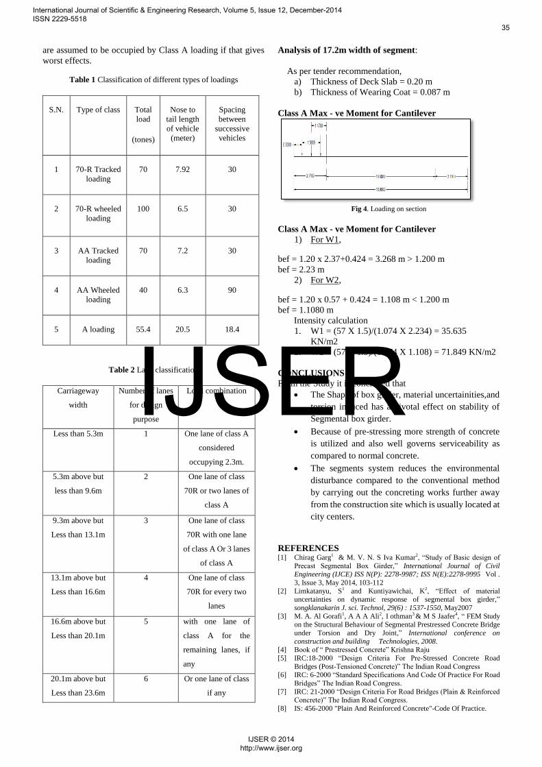
Analysis of 17.2m width of segment:
As per tender recommendation,
a) Thickness of Deck Slab = 0.20 m
b) Thickness of Wearing Coat = 0.087 m
Class A Max - ve Moment for Cantilever
Fig 4. Loading on section
Class A Max - ve Moment for Cantilever
1) For W1,
bef = 1.20 x 2.37+0.424 = 3.268 m > 1.200 m
bef = 2.23 m
2) For W2,
bef = 1.20 x 0.57 + 0.424 = 1.108 m < 1.200 m
bef = 1.1080 m
Intensity calculation
1. W1 = (57 X 1.5)/(1.074 X 2.234) = 35.635
KN/m2
2. W2 = (57 X 1.5)/(1.074 X 1.108) = 71.849 KN/m2
CONCLUSIONS
From the Study it is concluded that
The Shape of box girder, material uncertainities,and
torsion induced has a pivotal effect on stability of
Segmental box girder.
Because of pre-stressing more strength of concrete
is utilized and also well governs serviceability as
compared to normal concrete.
The segments system reduces the environmental
disturbance compared to the conventional method
by carrying out the concreting works further away
from the construction site which is usually located at
city centers.
REFERENCES
[1] Chirag Garg1 & M. V. N. S Iva Kumar2, “Study of Basic design of
Precast Segmental Box Girder,” International Journal of Civil Engineering (IJCE) ISS N(P): 2278-9987; ISS N(E):2278-9995 Vol .
3, Issue 3, May 2014, 103-112
[2] Limkatanyu, S1 and Kuntiyawichai, K2, “Effect of material uncertainties on dynamic response of segmental box girder,”
songklanakarin J. sci. Technol, 29(6) : 1537-1550, May2007
[3] M. A. Al Gorafi1, A A A Ali2, I othman3 & M S Jaafer4, “ FEM Study on the Structural Behaviour of Segmental Prestressed Concrete Bridge
under Torsion and Dry Joint,” International conference on
construction and building Technologies, 2008. [4] Book of “ Prestressed Concrete” Krishna Raju
[5] IRC:18-2000 “Design Criteria For Pre-Stressed Concrete Road
Bridges (Post-Tensioned Concrete)” The Indian Road Congress [6] IRC: 6-2000 “Standard Specifications And Code Of Practice For Road
Bridges” The Indian Road Congress.
[7] IRC: 21-2000 “Design Criteria For Road Bridges (Plain & Reinforced Concrete)” The Indian Road Congress.
[8] IS: 456-2000 "Plain And Reinforced Concrete"-Code Of Practice.
International Journal of Scientific & Engineering Research, Volume 5, Issue 12, December-2014 ISSN 2229-5518
35
IJSER © 2014 http://www.ijser.org
IJSER