internship report - ensta bretagne · this report describes my work during my internship in the...
TRANSCRIPT

Internship report
Autor: Clément Rolinat, SPID - Robotique
Internship supervisor: Maël Le Gallic

2
Table of Contents
Abstract 3
Context 4
Goals & concerns 4
Internship realisation 5
I) Deliberative collision avoidance 5
A) Introduction 5
B) Collision detection 6
C) Detection of the crossing of the sailing zone borders 9
D) Path replanning 10
E) Perspectives of improvement 17
II) Preparation for the WRSC 18
Economic analysis 19
Conclusion 20
Acknowledgment 21
References 22
Appendix 23

3
Abstract
This report describes my work during my internship in the Åland Sailing Robots
research team of the Åland University of Applied Science.
The main goal of this internship was to design a deliberative collision avoidance
algorithm. This algorithm should avoid the collision with the other boats, and avoid our boat
to cross the borders of a given sailing zone. It uses an interval analysis method. It is divided in
two main steps. The detection step check if there is any risk of collision or risk of crossing a
border of the sailing zone. If there is, the path replanning step start. It aims to choose a new
path, which avoid every obstacle, and in the same time assure that the boat doesn’t cross the
border of the sailing zone.
The end of my internship matched with the participation of the team to the World
Robotic Sailing Championship. I also took part in the preparation of this competition.

4
Context
My internship took place in the Åland Sailing Robots research team of the Åland
University of Applied Science. The goal of this research team is to develop an autonomous
sailboat, in order to develop Åland islands’ competency and innovation regarding unmanned
and autonomous shipping and green technology.
They are currently working on the ASPire project, which aims to develop a marine
research platform. This platform takes the shape of a 4 meters sailboat, with a free rotating
wingsail, which consists of a mainwing and a tailwing, instead of a classic soft sail. The goal of
this platform is to carry out some long survey missions in the Baltic sea, in order to gather
data on the water composition. This project has currently funding for three years, and at the
time of my internship the project was at the half of its development.
Figure 1: ASPire on her christening on July 2017
Goals & concerns
The main goal of my internship was to design a deliberative collision avoidance
algorithm. Indeed, during her missions, ASPire could meet some other boats, such as ferries,
containers ships, or pleasure boats. In order to assure her own safety and the safety of the

5
other boats, she has to be able to avoid them somehow. She also must stay in a defined sailing
zone, in order to avoid coasts and shallow waters.
A reactive collision avoidance algorithm has already been implemented. It is based on
a voter's system, which decide at a given frequency toward which direction the boat should
aim at. But this is most adapted for short range collision avoidance, because at long range this
algorithm can’t assure to reach the destination point in an efficient way.
For long range collision avoidance, the idea is to use a deliberative algorithm. It must
take into account all the information about every obstacle and allowed sailing zones, and
decide if it can follow the current path or if it has to change it. Currently, it is still at a prototype
and simulation stage, and it isn’t linked to the boat control system yet.
The end of my internship matched with our participation in the World Robotics Sailing
Championship (WRSC) in Horten, Norway. In order to prepare this competition, I contributed
to the development of the control system of the vessel and of its simulator. I was also involved
in the on-sea tests of this control system, before and during this competition.
Internship realisation
I) Deliberative collision avoidance
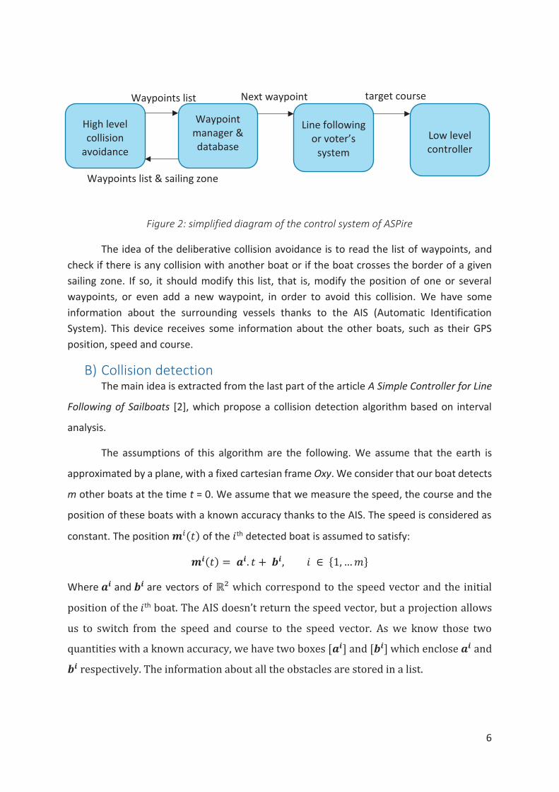
A) Introduction The control system of ASPire is organized on several levels. First, the lower level
controller has for inputs the desired course and the current course, and sends to the rudder
actuator and the tailwing actuator a command. Above that, we have currently two
possibilities available. The first option is a line following algorithm that takes for inputs two
waypoints, and sends to the lower level controller the desired course in order to follow the
line between the two waypoints. It considers the wind direction in order to allow the boat to
tack when needed. The other option is the reactive collision avoidance based on a voter’s
system. It considers the wind, the detected obstacles, and the next waypoint to determine a
target course. The list of every waypoints is stored in a database as a list of coordinates. A
waypoint manager checks when the next waypoint is reached, and if so, sends the new
waypoint to the line following algorithm.
6
Figure 2: simplified diagram of the control system of ASPire
The idea of the deliberative collision avoidance is to read the list of waypoints, and
check if there is any collision with another boat or if the boat crosses the border of a given
sailing zone. If so, it should modify this list, that is, modify the position of one or several
waypoints, or even add a new waypoint, in order to avoid this collision. We have some
information about the surrounding vessels thanks to the AIS (Automatic Identification
System). This device receives some information about the other boats, such as their GPS
position, speed and course.
B) Collision detection The main idea is extracted from the last part of the article A Simple Controller for Line
Following of Sailboats [2], which propose a collision detection algorithm based on interval
analysis.
The assumptions of this algorithm are the following. We assume that the earth is
approximated by a plane, with a fixed cartesian frame Oxy. We consider that our boat detects
m other boats at the time t = 0. We assume that we measure the speed, the course and the
position of these boats with a known accuracy thanks to the AIS. The speed is considered as
constant. The position !(") of the #th detected boat is assumed to satisfy:
$(") = &$. " + '$, # ∈ {1, … -}
Where &$ and '$ are vectors of ℝ² which correspond to the speed vector and the initial
position of the #th boat. The AIS doesn’t return the speed vector, but a projection allows
us to switch from the speed and course to the speed vector. As we know those two
quantities with a known accuracy, we have two boxes [&$] and ['$] which enclose &$ and '$ respectively. The information about all the obstacles are stored in a list.
High level collision
avoidance
Waypoint manager & database
Line following or voter’s
system
Low level controller
Waypoints list
Waypoints list & sailing zone
Next waypoint target course

7
Concerning our boat, we assume that its trajectory is the following:
0(") = &0. " + '0
The two vectors &0 and '0 depend on the line to be followed by our boat, so on the
position of the two waypoints that we want to link, on the speed of our boat, and on its
initial position. In a first approximation, we will assume that the initial position of the
boat is on the 1st waypoint. We also assume that the waypoints coordinates are expressed
in our fixed cartesian frame. We assume that we know the progression speed of the boat
on the followed line. In many case, it will correspond to the GPS speed projected on the
course, but when she tacks it won’t be the case. however, it will be possible to make an
estimation. Again, we can easily switch from the course and speed to the speed vector
with a projection. Here again, we will consider that we have two boxes [&0] and ['0]
which enclose &0 and '0.
In reality, the initial position of the boat may not be on the 1st waypoint. So, some
adjustment should be made in the current algorithm, for example create a waypoint on
the current position of the boat in the initialization of the algorithm. In any case, for the
good working of the method, we need to make sure that our boat is always somewhere
on the line between the two waypoints.
Then the article proposes a method based on Interval Analysis. It aims to prove that the robot’s trajectory is safe. The idea is to check in a time interval [0, tmax] if there is
a collision. There is a collision in our trajectory if:
∃# ∈ {1, … -}, ∃" ∈ [0, "456], $(") = 0(")
That is if the following system has a solution:
7 89: − 9!<. " + >: − >! = 0," ∈ [0, "456], # ∈ [1, … -]9: ∈ [9:], 9! ∈ ?9!@, >: ∈ [>:], >! ∈ [>!] By projecting this equation on x and y, and by combining the two equations obtained in a
3rd one, we get:

8
⎩⎪⎪⎨⎪⎪⎧
896: − 96! <. " + >6: − >6! = 0,89F: − 9F! <. " + >F: − >F! = 0,89F: − 9F! <8>6: − >6! < − 896: − 96! <8>F: − >F! < = 0," ∈ [0, "456], # ∈ [1, … -]96: ∈ [96:], 96! ∈ ?96! @, >6: ∈ [>6:], >6! ∈ [ >6! ]9F: ∈ ?9F:@, 9F! ∈ ?9F! @, >F: ∈ ?>F:@, >F! ∈ [ >F! ]
Then, if we express this system using intervals, we get that if:
∃# ∈ {1, … -}, G 0 ∈ 8[96:] − ?96! @< ∗ [0, "456] + [>6:] − ?>6! @ 9JK0 ∈ 8?9F:@ − ?9F! @< ∗ [0, "456] + ?>F:@ − ?>F! @ 9JK0 ∈ 8?9F:@ − ?9F! @< ∗ 8[>6:] − ?>6! @< − 8[96:] − ?96! @< ∗ 8?>F:@ − ?>F! @<
Then our boat will have a collision in the time interval [0, "456].
In order to check for collision between the two waypoints, we should take "456 so
that our boat reach the 2nd waypoint at "456. We can estimate "456, as we assume we
know the progression speed of the boat on the line between the two waypoints.
In case we have several waypoints, we can repeat this collision detection for each
segment of the trajectory. We assume that all the waypoints are stored in a list, and that
the last waypoint in the list is a checkpoint, that is we will have to reach it somehow and
we cannot modify it. It will be important for the path replanning step. In case we have
several waypoints, we must update the variables which represent the boat and obstacles
initial positions, so that they correspond to the value they should have at the beginning
of this new trajectory segment. We can calculate them because we consider that the speed
is constant, and that each trajectory is a line.
In case we detect a collision, we start the path replanning step, which will be
described later in the chapter D.

9
Figure 3: processing of the waypoint list and collision detection
C) Detection of the crossing of the sailing zone borders We decided to model the sailing zone as a list of polygons of which the boat shouldn’t
cross the sides. Each polygon is modelled by the list of the coordinates of its vertices. We
assume that those coordinates are expressed in a fixed cartesian frame. The crossing
conditions are inspired by the example presented in the article Path planning using intervals
and graphs [1].
We are in the same case than for the collision detection, that is the trajectory of our
boat is a segment between two waypoints. We can handle a case with several waypoints by
proceeding in the same way than in the collision detection. We consider that we have two
boxes A and B. The box A is the initial position of the boat, and the box B is the final position
of the boat. We denote by L! the #th vertex of a polygon. We assume that [M, N] denote the
set of all the segments with an endpoint in A and an endpoint in B. For each polygon of the
sailing zone, we need to check if:
∀#, ∀P ∈ [M, N], [L!, L!QR] ∩ P = ∅
If it’s true for all sides of all polygons, the boat never crosses the sailing zone border.
But it’s difficult to implement this relation. To avoid this issue, we will consider the
contrapositive and use these equivalent relations:
∃#, 7 ∃P ∈ [M, N], (L! , L!QR) ∩ P ≠ ∅ 9JK∃X ∈ (M, N), [L! , L!QR] ∩ X ≠ ∅ 9JK[L! ∪ L!QR] ∩ [M ∪ N] ≠ ∅

10
We assume that (M, N) denote the set of all the lines supported by a point in A and a point in
B, (L!, L!QR) the line supported by L! and L!QR, [L!, L!QR] the segment linking L! and L!QR, and [M ∪ N] and [L! ∪ L!QR] the smallest box including A and B or L! and L!QR respectively.
The last condition is important for a special case, where all the points are aligned. In
that case, the two first conditions will be true event if the trajectory doesn’t intersect the
polygon side.
We can’t implement directly the two first conditions, so we will use the following
equivalence in the code instead:
∃#, GKZ"8L\N^̂ ^̂ ^⃗ , L\M^̂^̂ ^⃗ < ∗ KZ"8L\QRN^̂^̂ ^̂ ^̂ ^̂ ^⃗ , L\QRM^̂^̂^̂ ^̂ ^̂ ^⃗ < ≤ 0 9JKKZ"8L\QRL\^̂ ^̂ ^̂ ^̂ ^̂ ^⃗ , L\M^̂^̂ ^⃗ < ∗ KZ"8L\QRL\^̂ ^̂ ^̂ ^̂ ^̂ ^⃗ , L\N^̂ ^̂ ^⃗ < ≤ 0 9JK[L! ∪ L!QR] ∩ [M ∪ N] ≠ ∅
If it’s true for one of the polygon of the sailing zone, then the boat trajectory is crossing this
polygon.
As A and B are boxes, the coordinates of the vectors are some intervals, and the result of the
determinants are intervals too. So, in fact we manipulate a set of vectors and a set of
determinants. The mathematical notations may be inappropriate, but in practice it gives some
good results. We make this test just after the collision detection. If we detect that the boat
will cross the sailing zone border, we call the path replanning method.
Figure 4: detection of the crossing of the sailing zone borders
D) Path replanning The second part, that is the modification of the list of waypoints, is a path planning
problem with dynamic obstacles. Some path planning problems, with static obstacles, can be
solved easily and efficiently with interval analysis method and graphs [1]. But the dynamic
obstacles make this approach much more difficult, because it also depends on time, and it’s
harder to define the configuration space.

11
The issue of dynamic path planning is not trivial, and the solution often chosen is to
consider that the obstacles are static, and make the calculation at a high frequency in order
to take into account the fact that the obstacles are moving. This solution is simple on the
theoretical level, and easy to implement, but it is not efficient, and it can be unsafe in some
situations. Some solution for the dynamic path planning had been developed recently. But
often, the papers describing those solutions aren’t freely available. And when they are, those
solutions are complex on the theoretical level, and we were not sure to have the skill and the
time required to adapt it to our situation and to implement it.
As the detection step uses some interval analysis, we choose to use the same
approach for the path replanning step. The general idea is to compute the set of all the speed
vectors that allow our boat to avoid a collision and that allow it to stay in the sailing zone.
For that, we use the separator algebra. We build a separator corresponding to the
collision condition of each obstacles, and to the crossing condition of each side of each
polygon of the sailing zone. Then, we compute the union of all these separators. Finally, we
can compute with a paving method the set of all the feasible speed vectors, that is the set
which avoid collisions and which avoid crossing the sailing zone borders. Then, we choose the
speed vector which is the closest to our initial speed vector.
We keep this speed vector during the same amount of time as it would take to our
boat to reach the waypoint with its previous speed vector. This assumption allows us to
compute a new waypoint, and to replace the former one by this one. For the last waypoint of
the list, we assume it is a checkpoint, so we shouldn’t modify it. In that case, we add a new
waypoint before the last one, instead of directly modifying it. However, if we are close enough
to the last waypoint, that is if the last waypoint is inside the final position uncertainty box of
the boat, we replace the last waypoint. It allows us to avoid some bugs link to the size of the
uncertainty box. If we compute a very long path, at the end the uncertainty box is so huge
that it could be impossible for the center of the box to reach the waypoint without a part of
the box collide with something or cross a border.
Collision separators
To build the collision separators, we use the same conditions than in the detection
part. We build one intermediary separator for each condition, then compute the intersection.
12
Then this separator, which correspond to one obstacle, goes in a list. This list aims to store all
the separators in order to make the union when we have built them all.
However, there is an issue with these conditions. Indeed, the inside of the set they
produce is empty. It produces a lot of boxes during the paving process and it can lead to a
very long execution time. In order to bypass this issue, we needed to rephrase these
constraints. We also needed to use the separators associated to the projection of the set
defined by the separator built with these constraints. Indeed, the dimension of the separators
is too high to allow them to have a non-empty inside. The projection allows us to decrease
this dimension. We rephrased the constraints as follow:
∃# ∈ {1, … -},⎩⎪⎨⎪⎧ ?>6! @ − [>6:] ∈ 8[96:] − ?96! @< ∗ [0, "456] 9JK?>F! @ − ?>F:@ ∈ 8?9F:@ − ?9F! @< ∗ [0, "456] 9JK
8?>F! @ − ?>F:@< ∈ 8?9F:@ − ?9F! @<8[96:] − ?96! @< ∗ 8?>6! @ − [>6:]< After building the separators linked with these constraints, we build the separators of
their projection. Then, we make the intersection of these three separators of projection.
Finally, we can add them in the separator list, as previously.
But the fact is that the projection operation is quite slow, so the execution time doesn’t improve as expected. Depending on the resolution of the paving and the number of obstacles, in some cases it’s faster to use projection, and in other cases, it’s faster without using it. So, we decided to let the two version in the code, and to allow the user
to choose which version he wants to use. That way, it will be easy to make more tests, and
eventually decide later which version we should use.
Example
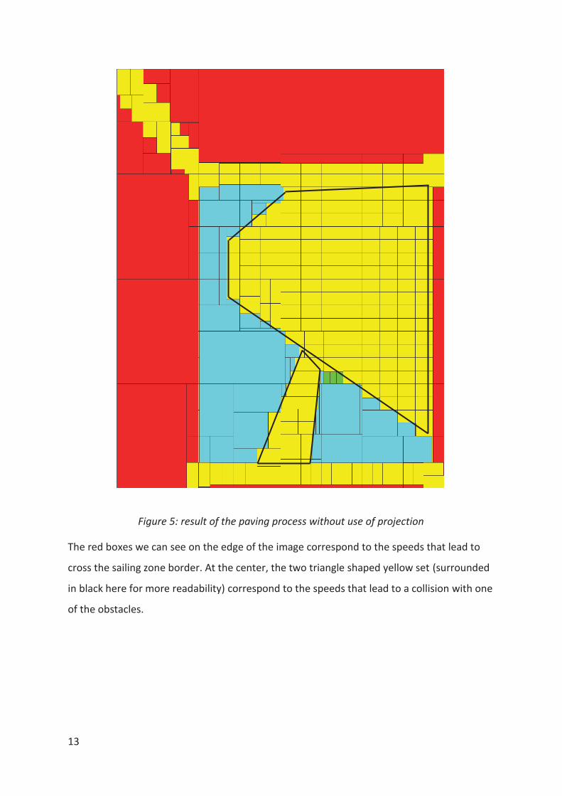
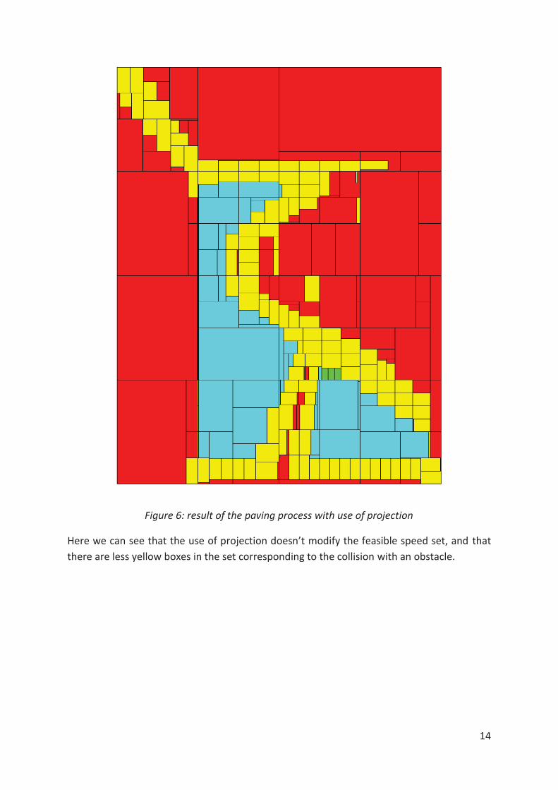
On figure 5 & 6, you can see two paving made in the same conditions. There are
three obstacles, and the sailing zone is defined by a square around the evolution area of
our boat.
The red boxes are inside the set of speed vectors that lead to a collision or to cross
a border of the sailing zone. The Yellow boxes are on the border of this set. Finally, the
light blue boxes are outside this set, so they represent the set of the feasible speed vectors.
The green box is the speed vector chosen by the algorithm.
13
Figure 5: result of the paving process without use of projection
The red boxes we can see on the edge of the image correspond to the speeds that lead to
cross the sailing zone border. At the center, the two triangle shaped yellow set (surrounded
in black here for more readability) correspond to the speeds that lead to a collision with one
of the obstacles.
14
Figure 6: result of the paving process with use of projection
Here we can see that the use of projection doesn’t modify the feasible speed set, and that
there are less yellow boxes in the set corresponding to the collision with an obstacle.

15
Figure 7: trajectories of the boats
On figure 7 we can see the trajectories of the different boats. In red is displayed the
sailing zone borders. In yellow we can see the initially planned path of our boat. In black, there
are the paths of the other boats that we need to avoid. Finally, in blue is displayed the path
16
of our boat after the collision avoidance. We are not able to see it here, but at run time we
display the different uncertainty boxes moving on their paths.
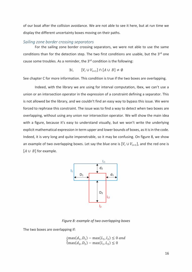
Sailing zone border crossing separators
For the sailing zone border crossing separators, we were not able to use the same
conditions than for the detection step. The two first conditions are usable, but the 3rd one
cause some troubles. As a reminder, the 3rd condition is the following:
∃#, [L! ∪ L!QR] ∩ [M ∪ N] ≠ ∅
See chapter C for more information. This condition is true if the two boxes are overlapping.
Indeed, with the library we are using for interval computation, Ibex, we can’t use a
union or an intersection operator in the expression of a constraint defining a separator. This
is not allowed be the library, and we couldn’t find an easy way to bypass this issue. We were
forced to rephrase this constraint. The issue was to find a way to detect when two boxes are
overlapping, without using any union nor intersection operator. We will show the main idea
with a figure, because it’s easy to understand visually, but we won’t write the underlying
explicit mathematical expression in term upper and lower bounds of boxes, as it is in the code.
Indeed, it is very long and quite impenetrable, so it may be confusing. On figure 8, we show
an example of two overlapping boxes. Let say the blue one is [L! ∪ L!QR], and the red one is [M ∪ N] for example.
Figure 8: example of two overlapping boxes
The two boxes are overlapping if:
zmax(KR, XR) − max(|R, ~�) ≤ 0 9JKmax(K�, X�) − max(~R, |�) ≤ 0
l1
L1
l2
L2
D1 d1
D2
d2

17
These conditions are used to build the separator, but the real expression is much more
complex. Indeed, all the variables depend on the relative position of the upper bounds or
lower bounds of the boxes A or B, and on the relative position of the two vertices.
Then, the separator corresponding to one side of a polygon is added in the separator
list, in the same way as for the collision condition separators.
E) Perspectives of improvement The various tests we made allowed us to find some potential issues with the actual
algorithm that may cause some troubles when we will use this algorithm in real conditions.
First, for now the algorithm assume that we can control the speed of our boat when
it chooses a new speed vector. Theoretically, it depends on the projection on the boat course
of the force applied on the wingsail, so on the wind speed and direction, on the heading of
the boat, and on the angle of attack of the wingsail. In theory, the angle of attack is controlled
thanks to the angle of the tailwing. So, it seemed to be possible to control the speed of the
boat. In practice, the on-sea tests we made show that it is very difficult to control the speed
of the boat because it depends on too many parameters. A simple way to bypass this issue
could be to choose a new speed vector which has the same norm as the actual speed vector.
Indeed, it will require more tests in real conditions, but it might be possible to assume that
our speed can remain constant, as soon as we process the collision avoidance on a reasonable
time interval, for example about few tens of minutes.
There may be some issue when we choose a direction where the boat will have to tack.
Indeed, the progression speed of the boat on the segment will be slightly slower than when
it doesn’t need to tack. This case need to be checked, because fixing this issue will require to
complexify the algorithm. Indeed, if we can’t choose the same speed norm than the actual
speed for some directions, we will need to know somehow which are these directions, and
which speed norm we can have in these directions. For that, the choose of the speed vector
will have to take into account the wind direction.
Another issue is linked to the uncertainty box corresponding to the position of our
boat. Actually, it doesn’t match the real uncertainty we have about the position of the boat.
Indeed, for each trajectory segment, we know that the boat will follow a line between the
two waypoints, and will stay in a given corridor around this line. So, the box shape doesn’t fit
with this knowledge. It causes some trouble when we process the collision avoidance on a

18
long amount of time. Indeed, the uncertainty box become huge, but it’s not consistent with
the reality, because we know that our boat will stay in a corridor around the line. The only
thing we don’t know is where exactly our boat is in this corridor, mainly because of the speed
uncertainty. It’s an issue, because if the uncertainty box is too large, it will detect some
collision whereas in reality there is no risk. In some cases when the box is very large, the set
of feasible speed vector can even become empty, and the algorithm will stop without finding
any path. So, we must choose carefully the amount of time on which we want to process the
collision avoidance, and make sure it isn’t too long. To avoid this issue, a simple solution would
be to consider that the speed isn’t an interval, but a fixed value. In that case the uncertainty
box corresponding to the position of our boat would have a fixed size. Of course, we would
lose partly the interest of the interval analysis, that allow us to take into account uncertainties.
It will require some tests in real conditions, because if in reality the speed of our boat doesn’t
vary a lot between two waypoints, the use of an interval to model it isn’t necessary.
II) Preparation for the WRSC
The end of my internship matched with the participation of the ASPire project team
to the WRSC (World Robotic Sailing Championship). In order to prepare this competition, we
needed to have a working simulator, to test the control system before the on-sea tests.
The simulator was reworked this summer and it wasn’t working properly yet. I was
assigned with fixing the remaining issue with this simulator. It is organised on a client-server
architecture. The server is the control system, and the client is the simulator and the display.
A lot of issues was linked to some conversion errors between two conventions. Indeed, the
control system use a north east down convention, and the simulator an east north up
convention. Moreover, in the simulator the angles are in the range [-180, 180], whereas in
the control system they are in the range [0, 360]. So, my main task was to check for each
variable that was sent from one side to another if it was in the right convention on both sides.
But when all the convention issues were fixed, the simulated boat still had some
illogical behaviours. I was assigned with investigating these remaining issues. I finally found
out that there was something wrong with the calculation of the force on the wingsail. I
couldn’t find exactly what was wrong, but the value and the sign of the force seems
19
incoherent with the heading of the boat and the wind direction. So, some further
investigation should be made on this part of the code, and maybe the physics equations
should be checked too.
I was also charged to develop a station keeping controller for the station keeping task
of the WRSC. The idea was to take advantage of the ability of our boat to go backward thanks
to the wingsail, to adjust our position as close as possible to the waypoint. Indeed, we could
stop on the waypoint, and if we start to drift forward, we could go back to the waypoint.
Likewise, if we drift backward, we could reach back to it. However, we haven’t any means to
know the direction of our speed at low speed. Indeed, we use the GPS speed, but at low speed
its direction is irrelevant. Without this knowledge, we can’t control correctly the rudder and
the tailwing, because obviously it won’t be the same control if we are going backward as if we
are going forward. Finally, we used the controller developed last year, which try to go back to
the waypoint when the boat passed it, using the line following controller. In practice, the boat
keeps turning around the waypoint.
Finally, during the WRSC, I was involved in the on-sea tests, and in the trials
preparation.
Economic analysis
The ASPire project is financed for three years by the European Union, through the
European Regional Development Fund (50%) and the Åland government, through the Åland's
program for structural funds "Entrepreneurship and competency" (50%). They contributed up
to around 350 000€.
Around 80% of this budget is dedicated to personnel costs. This include the project
leader wages for 3 years, 11.5 months of wages for a software developer, and 6.5 months of
wages for an electronic and mechanical engineer. A part of this budget is also dedicated to
some internships. Nevertheless, my internship wasn’t on this budget. Indeed, as it was an
Erasmus internship, I was paid by Erasmus.
About 9%, that is around 30 000€, of the total budget is allocated to the purchase of
services. For example, the seaworthiness calculation, some part of the construction of the
20
boat, the dimensioning and the construction of the wingsail, weren’t realised by the project
team, but were subcontracted.
Approximately the same part of the budget is dedicated to the purchase of materials
(electronic and mechanical) and tools, and the renting of machines and devices. However,
this budget is already almost entirely used whereas the project should still last for one year
and a half. Indeed, a great part of the construction wasn’t subcontracted, and some of the
building work that needed to be done was hardly predictable.
Finally, the remaining budget is allocated to travel expenses, such as travel allowances,
tickets, food & lodging, car costs… For example, this budget was used for attendance at HIPER
2017 and OCEANS 2017 conferences. Our trip to Norway for the WRSC and the expenses
made during our stay wasn’t on this budget, but on the budget of the Finnish Maritime
foundation.
Conclusion
First, this internship was for me the opportunity to gain a lot of technical skill, in some
various fields. First, I was able to increase my knowledge about interval analysis. Then, As the
whole project is in C++, it allowed me to practice this language a lot, and more particularly
the interval library, Ibex. Moreover, I’m now familiar with the git workflow, as the project is
using it. It was also the occasion to work in an international team, and to practice the scrum,
a project management method. So, on the technical field this internship was very rewarding.
It also allowed me to have an insight of the research world, as I was integrated in a
research team in the Åland University of Applied Science, and as my internship subject was
research oriented. This experience confirmed my wish to work in this sector.
So, this internship was very interesting on many aspects, and I hope my work will be
useful for the future developments of the project.

21
Acknowledgment
I thank Anna Friebe, my project manager, for offering me the opportunity to make this
internship, and for being as available as she could to answer my questions, on technical or
practical concerns.
I also thank Luc Jaulin, my school internship supervisor and one of my teachers, for giving me
Anna’s contact for this internship, and for his advices and explanations about interval analysis.
Finally, I thank Maël Le Gallic, my internship supervisor, for making sure that I had all the
information to understand well the goal of my internship subject and the actual status of the
project in general. I also thank him for revising this report.

22
References
[1] Luc Jaulin, Path planning using intervals and graphs, Reliable Computing Journal, 2001,
7(1), pp.1-15
[2] Luc Jaulin, Fabrice Le Bars, A Simple Controller for Line Following of Sailboats, Robotic
Sailing 2012, p 117-129
23
Appendix

