interoperability unit trans-european conventional rail ... report... · the transition period ......
TRANSCRIPT
EUROPEAN RAILWAY AGENCY
File: IU-ENE-090916-TSI 5 0.doc Page 1 of 64
INTEROPERABILITY UNIT
TRANS-EUROPEAN CONVENTIONAL RAIL SYSTEM
SUBSYSTEM ENERGY
Reference: IU-ENE-090916-TSI 5.0 Document
Type:
Technical Specification of Interoperability
Version: 5.0 Title: TSI
Date: 16/09/2009
Edited by Reviewed by Approved by
Name Stanislaw LIS Gianvittorio TAVOLA
Andrzej HARASSEK Jean-Charles PICHANT
Position Project Officers Adviser Head of Unit
Date
&
Signature
ERA INTEROPERABILITY UNIT
File: IU-ENE-090916-TSI 5 0.doc Page 2 of 64
Amendment record
Version Date Section
number
Modification/
Description Author
3.0 14/05/2009 All Approval by ERA for DG
TREN
Stanislaw Lis Gianvittorio Tavola
4.0 31/07/2009 All
After comments during RISC workshop and
Slovenian SCs + conformity assessment in chapter 6
Stanislaw Lis Gianvittorio Tavola
5.0 31/08/2009 All Editorial corrections Stanislaw Lis Gianvittorio Tavola
5.0 16/09/2009 All Editorial corrections –
clause 4.3, 6.3
Stanislaw Lis Gianvittorio Tavola
ERA INTEROPERABILITY UNIT
File: IU-ENE-090916-TSI 5 0.doc Page 3 of 64
Table of contents
1. INTRODUCTION ......................................................................................................... 6
1.1. Technical scope ..................................................................................................... 6
1.2. Geographical scope ............................................................................................... 6
1.3. Content of this TSI ................................................................................................. 6
2. DEFINITION AND SCOPE OF THE SUBSYSTEM .................................................... 7
2.1. Definition of the energy sub-system..................................................................... 7
2.1.1. Power supply ......................................................................................... 8 2.1.2. Overhead contact line and pantograph .................................................. 8
2.2. Interfaces with other subsystems and within the subsystem ............................ 9
2.2.1. Introduction ............................................................................................ 9 2.2.2. Interfaces concerning power supply ....................................................... 9 2.2.3. Interfaces concerning overhead line equipment and pantographs and
their interaction ...................................................................................... 9 2.2.4. Interfaces concerning phase and system separation sections ............... 9
3. ESSENTIAL REQUIREMENTS ................................................................................ 11
4. CHARACTERISATION OF THE SUBSYSTEM ........................................................ 13
4.1. Introduction .......................................................................................................... 13
4.2. Functional and technical specifications of the subsystem .............................. 13
4.2.1. General provisions ............................................................................... 13 4.2.2. Basic parameters characterising the energy subsystem ...................... 13 4.2.3. Voltage and frequency ......................................................................... 14 4.2.4. Parameters relating to supply system performance ............................. 14 4.2.5. Continuity of power supply in case of disturbances in tunnels .............. 15 4.2.6. Current capacity, DC systems, trains at standstill ................................ 15 4.2.7. Regenerative braking ........................................................................... 15 4.2.8. Electrical protection coordination arrangements .................................. 15 4.2.9. Harmonics and dynamic effects for AC systems .................................. 15 4.2.10. Harmonic emissions towards the power utility ...................................... 15 4.2.11. External electromagnetic compatibility ................................................. 15 4.2.12. Protection of the environment .............................................................. 16 4.2.13. Geometry of the overhead contact line ................................................ 16 4.2.14. Pantograph gauge ............................................................................... 18 4.2.15. Mean contact force .............................................................................. 18 4.2.16. Dynamic behaviour and quality of current collection ............................ 18 4.2.17. Pantograph spacing ............................................................................. 20 4.2.18. Contact wire material ........................................................................... 20 4.2.19. Phase separation sections ................................................................... 20 4.2.20. System separation sections ................................................................. 21 4.2.21. Electric energy consumption measuring equipment ............................. 21
4.3. Functional and technical specifications of the interfaces ................................ 23
4.3.1. General requirements .......................................................................... 23 4.3.2. Locomotives and Passenger Rolling Stock .......................................... 23 4.3.3. Infrastructure ....................................................................................... 23 4.3.4. Control - Command and Signalling ...................................................... 24 4.3.5. Traffic Operation and Management ..................................................... 24 4.3.6. Safety in Railway Tunnels .................................................................... 24
ERA INTEROPERABILITY UNIT
File: IU-ENE-090916-TSI 5 0.doc Page 4 of 64
4.4. Operating rules .................................................................................................... 25
4.4.1. Introduction .......................................................................................... 25 4.4.2. Management of power supply .............................................................. 25 4.4.3. Execution of works ............................................................................... 25
4.5. Maintenance rules ................................................................................................ 25
4.6. Professional qualifications.................................................................................. 26
4.7. Health and safety conditions .............................................................................. 26
4.7.1. Introduction .......................................................................................... 26 4.7.2. Protective provisions of substations and sectioning locations .............. 26 4.7.3. Protective provisions of overhead contact line system ......................... 26 4.7.4. Protective provisions of current return circuit ....................................... 26 4.7.5. Other general requirements ................................................................. 27 4.7.6. High Visibility Clothing .......................................................................... 27
4.8. Register of Infrastructure and Register of rolling stock ................................... 27
4.8.1. Introduction .......................................................................................... 27 4.8.2. Register of infrastructure...................................................................... 27 4.8.3. Register of rolling stock........................................................................ 27
5. INTEROPERABILITY CONSTITUENTS ................................................................... 28
5.1. List of constituents .............................................................................................. 28
5.2. Constituents' performances and specifications ................................................ 29
5.2.1. Overhead contact line .......................................................................... 29
6. ASSESSMENT OF CONFORMITY OF THE INTEROPERABILITY CONSTITUENTS
AND EC VERIFICATION OF THE SUBSYSTEMS ................................................... 30
6.1. Interoperability Constituents .............................................................................. 30
6.1.1. Conformity assessment procedures ..................................................... 30 6.1.2. Application of modules ......................................................................... 30 6.1.3. Innovative solutions for Interoperability Constituents ........................... 30 6.1.4. Particular assessment procedure for Interoperability Constituent - OCL31 6.1.5. EC declaration of conformity of Interoperability Constituents ............... 32
6.2. Energy subsystem ............................................................................................... 32
6.2.1. General provisions ............................................................................... 32 6.2.2. Application of modules ......................................................................... 32 6.2.3. Innovative solutions ............................................................................. 32 6.2.4. Particular assessment procedures for Subsystem ............................... 33
6.3. Sub-system containing Interoperability Constituents not holding an EC
declaration ............................................................................................................ 34
6.3.1. General ................................................................................................ 34 6.3.2. The transition period ............................................................................ 34 6.3.3. The certification of subsystems containing non-certified Interoperability
Constituents during the transition period .............................................. 34
7. IMPLEMENTATION .................................................................................................. 36
7.1. General ................................................................................................................. 36
7.2. Progressive strategy towards interoperability................................................... 36
7.2.1. Introduction .......................................................................................... 36 7.2.2. Migration strategy for voltage and frequency ....................................... 36 7.2.3. Migration strategy for pantographs and OCL geometry........................ 36
7.3. Application of this TSI to new lines .................................................................... 36
ERA INTEROPERABILITY UNIT
File: IU-ENE-090916-TSI 5 0.doc Page 5 of 64
7.4. Application of this TSI to existing lines.............................................................. 36
7.4.1. Introduction .......................................................................................... 36 7.4.2. Upgrading/renewal of the OCL and/or the power supply ...................... 37 7.4.3. Parameters related to maintenance ..................................................... 37 7.4.4. Existing subsystem that are not subject to a renewal or upgrading
project .................................................................................................. 37 7.5. Specific cases ...................................................................................................... 37
7.5.1. Introduction .......................................................................................... 37 7.5.2. List of specific cases ............................................................................ 37
8. LIST OF ANNEXES .................................................................................................. 42
ANNEX A – CONFORMITY ASSESSMENT OF INTEROPERABILITY CONSTITUENTS43
ANNEX B – EC VERIFICATION OF THE ENERGY SUBSYSTEM .................................. 44
ANNEX C – REGISTER OF INFRASTRUCTURE, INFORMATION ON THE ENERGY
SUBSYSTEM ............................................................................................................ 46
ANNEX D – REGISTER OF ROLLING STOCK, INFORMATION REQUIRED BY THE
ENERGY SUBSYSTEM ............................................................................................ 47
ANNEX E – DETERMINATION OF THE MECHANICAL KINEMATIC PANTOGRAPH
GAUGE ..................................................................................................................... 48
ANNEX F – PHASE AND SYSTEM SEPARATION SECTION SOLUTIONS .................... 57
ANNEX G – POWER FACTOR ......................................................................................... 59
ANNEX H – ELECTRICAL PROTECTION: MAIN CIRCUIT BREAKER TRIPPING ......... 60
ANNEX I – LIST OF REFERENCED STANDARDS .......................................................... 61
ANNEX Z – GLOSSARY ................................................................................................... 63
ERA INTEROPERABILITY UNIT
File: IU-ENE-090916-TSI 5 0.doc Page 6 of 64
1. Introduction
1.1. Technical scope
This TSI concerns the energy subsystem of the trans-European conventional rail system. The energy subsystem is included in the list of subsystems in Annex II to the Directive 2008/57/EC.
1.2. Geographical scope
The geographical scope of this TSI is the trans-European conventional rail system as described in Annex I chapter 1.1 to the Directive 2008/57/EC.
1.3. Content of this TSI
In accordance with Article 5(3) of the Directive 2008/57/EC, this TSI:
a. indicates its intended scope – Chapter 2;
b. lays down essential requirements for energy subsystem – Chapter 3;
c. establishes the functional and technical specifications to be met by the subsystem and its interfaces vis-à-vis other subsystems – Chapter 4;
d. determines the interoperability constituents and interfaces that must be covered by European specifications, including European standards, which are necessary to achieve interoperability within the rail system – Chapter 5;
e. states, in each case under consideration, which procedures are to be used in order to assess the conformity or the suitability for use of the interoperability constituents on the one hand, and the EC verification of the subsystems, on the other hand - Chapter 6;
f. indicates the strategy for implementing the TSI. In particular, it is necessary to specify the stages to be completed in order to make a gradual transition from the existing situation to the final situation in which compliance with the TSI shall be the norm – Chapter 7;
g. indicates, for the staff concerned, the professional qualifications and health and safety conditions at work required for the operation and maintenance of the subsystem concerned, as well as for the implementation of the TSI – Chapter 4.
Moreover, in accordance with Article 5(5), provision may be made for specific cases; these are indicated in Chapter 7.
Lastly, this TSI also comprises, in Chapter 4, the operating and maintenance rules specific to the scope indicated in paragraphs 1.1 and 1.2 above.
ERA INTEROPERABILITY UNIT
File: IU-ENE-090916-TSI 5 0.doc Page 7 of 64
2. Definition and scope of the subsystem
2.1. Definition of the energy subsystem
The Energy TSI specifies those requirements which are necessary to assure the interoperability of the rail system. This TSI covers all fixed installations, DC or AC that are required to supply, with respect to the essential requirements, traction energy to a train.
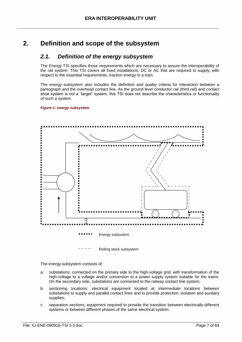
The energy subsystem also includes the definition and quality criteria for interaction between a pantograph and the overhead contact line. As the ground level conductor rail (third rail) and contact shoe system is not a ―target‖ system, this TSI does not describe the characteristics or functionality of such a system.
Figure 1: energy subsystem
The energy subsystem consists of:
a. substations: connected on the primary side to the high-voltage grid, with transformation of the high-voltage to a voltage and/or conversion to a power supply system suitable for the trains. On the secondary side, substations are connected to the railway contact line system;
b. sectioning locations: electrical equipment located at intermediate locations between substations to supply and parallel contact lines and to provide protection, isolation and auxiliary supplies;
c. separation sections: equipment required to provide the transition between electrically different systems or between different phases of the same electrical system;
Energy subsystem
Rolling stock subsystem
ERA INTEROPERABILITY UNIT
File: IU-ENE-090916-TSI 5 0.doc Page 8 of 64
d. contact line system: a system that distributes the electrical energy to the trains running on the route and transmits it to the trains by means of current collectors. The contact line system is also equipped with manually or remotely controlled disconnectors which are required to isolate sections or groups of the contact line system according to operational necessity. Feeder lines are also part of the contact line system;
e. return circuit: all conductors which form the intended path for the traction return current and which are additionally used under fault conditions. Therefore, so far as this aspect is concerned, the return circuit is part of the energy subsystem and has an interface with the infrastructure subsystem.
In addition, according to the Directive 2008/57/EC, the energy subsystem includes:
f. on-board parts of the electric consumption measuring equipment - for measurement of electric energy taken from or returned to (during regenerative braking) the contact line by the vehicle, supplied from the external electric traction system. The equipment is integrated into and put into service with the traction unit, and is in the scope of the conventional rail locomotives and passenger rolling stock TSI (CR LOC&PAS).
The Directive 2008/57/EC also foresees that the current collectors (pantographs), which transmit electrical energy from the overhead contact line system to the vehicle, are in the rolling stock subsystem. They are installed and are integrated into and put into service with the rolling stock and are in the scope of CR LOC&PAS TSI.
However, the parameters relating to the quality of current collection are specified in CR ENE TSI.
2.1.1. Power supply
The power supply system has to be designed such that every train will be supplied with the necessary power. Therefore, the supply voltage, current draw of each train and the operating schedule are important aspects for performance.
As with any electrical device, a train is designed to operate correctly with a nominal voltage and a nominal frequency applied at its terminals, i.e. the pantograph(s) and wheels. Variations and limits of these parameters need to be defined in order to assure the anticipated train performance.
Modern, electrically powered trains are often capable of using regenerative braking to return energy to the power supply, reducing power consumption overall. The power supply system can be designed to accommodate such regenerative braking energy.
In any power supply, short-circuits and other fault conditions may occur. The power supply needs to be designed so that the controls detect these faults immediately and trigger measures to remove the short-circuit current and isolate the affected part of the circuit. After such events, the power supply has to be able to restore supply to all installations as soon as possible in order to resume operations.
2.1.2. Overhead contact line and pantograph
A compatible geometry of the overhead contact line to the pantograph is an important aspect of interoperability. As far as geometrical interaction is concerned, the height of the contact wire above the rails, the variation in contact wire height, the lateral deviation under wind pressure and the contact force have to be specified. The geometry of the pantograph head is also fundamental to assure good interaction with the overhead contact line, taking into account vehicle sway.
In order to support interoperability of European networks, the pantographs specified in CR LOC&PAS TSI are the target.
ERA INTEROPERABILITY UNIT
File: IU-ENE-090916-TSI 5 0.doc Page 9 of 64
The interaction between an overhead contact line and a pantograph represents a very important aspect in establishing reliable power transmission without undue disturbances to railway installations and the environment. This interaction is mainly determined by:
a. static and aerodynamic effects dependent upon the nature of the pantograph contact strips and the design of the pantograph, the shape of the vehicle on which the pantograph(s) is (are) mounted and the position of the pantograph on the vehicle,
b. the compatibility of the contact strip material with the contact wire,
c. the dynamic characteristics of the overhead contact line and pantograph(s) for single unit or multiple unit trains,
d. the number of pantographs in service and the distance between them, since each pantograph can interfere with the others on the same overhead contact line section.
2.2. Interfaces with other subsystems and within the
subsystem
2.2.1. Introduction
The energy subsystem interfaces with some of the other subsystems of the rail system in order to achieve the envisaged performance. These are listed below:
2.2.2. Interfaces concerning power supply
a. Voltage and frequency and their permissible ranges interface with the rolling stock subsystem.
b. The power installed on the lines and the specified power factor determines the performance of the rail system and interfaces with the rolling stock subsystem.
c. Regenerative braking reduces energy consumption and interfaces with the rolling stock subsystem.
d. Electrical fixed installations and on-board traction equipment need to be protected against short circuits. Circuit breaker tripping in substations and on trains has to be coordinated. Electrical protection interfaces with the rolling stock subsystem.
e. Electrical interference and harmonic emissions interface with the rolling stock and control-command and signalling subsystems.
f. The current return circuit has some interfaces with control-command and signalling and infrastructure subsystems.
2.2.3. Interfaces concerning overhead line equipment and
pantographs and their interaction
a. The contact wire gradient and rate of change of gradient needs special attention in order to avoid loss of contact and excessive wear. The contact wire height and gradient interfaces with the infrastructure and rolling stock subsystems.
b. Vehicle and pantograph sway interfaces with the infrastructure subsystem.
c. The quality of current collection depends on the number of pantographs in service, their spacing and other traction-unit-specific details. The arrangement of pantographs interfaces with the rolling stock subsystem.
2.2.4. Interfaces concerning phase and system separation sections
a. To pass transitions between different power supply system and phase separation sections, without bridging, the number and arrangement of pantographs on trains shall be stipulated. This interfaces with the rolling stock subsystem.
ERA INTEROPERABILITY UNIT
File: IU-ENE-090916-TSI 5 0.doc Page 10 of 64
b. To pass transitions of power supply system and phase separation sections, without bridging, control of train current is required. This interfaces with the control-command and signalling subsystem.
c. When passing through power supply system separation sections, lowering of pantograph(s) may be required. This interfaces with the control-command and signalling subsystem.
ERA INTEROPERABILITY UNIT
File: IU-ENE-090916-TSI 5 0.doc Page 11 of 64
3. Essential requirements
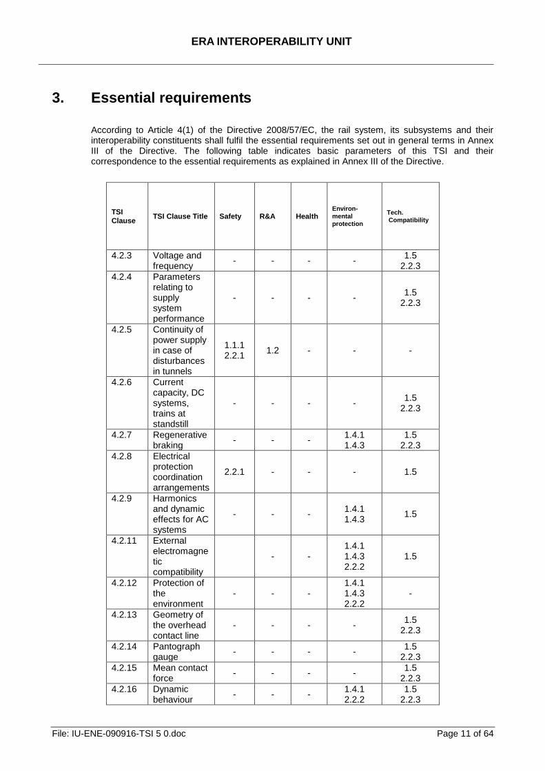
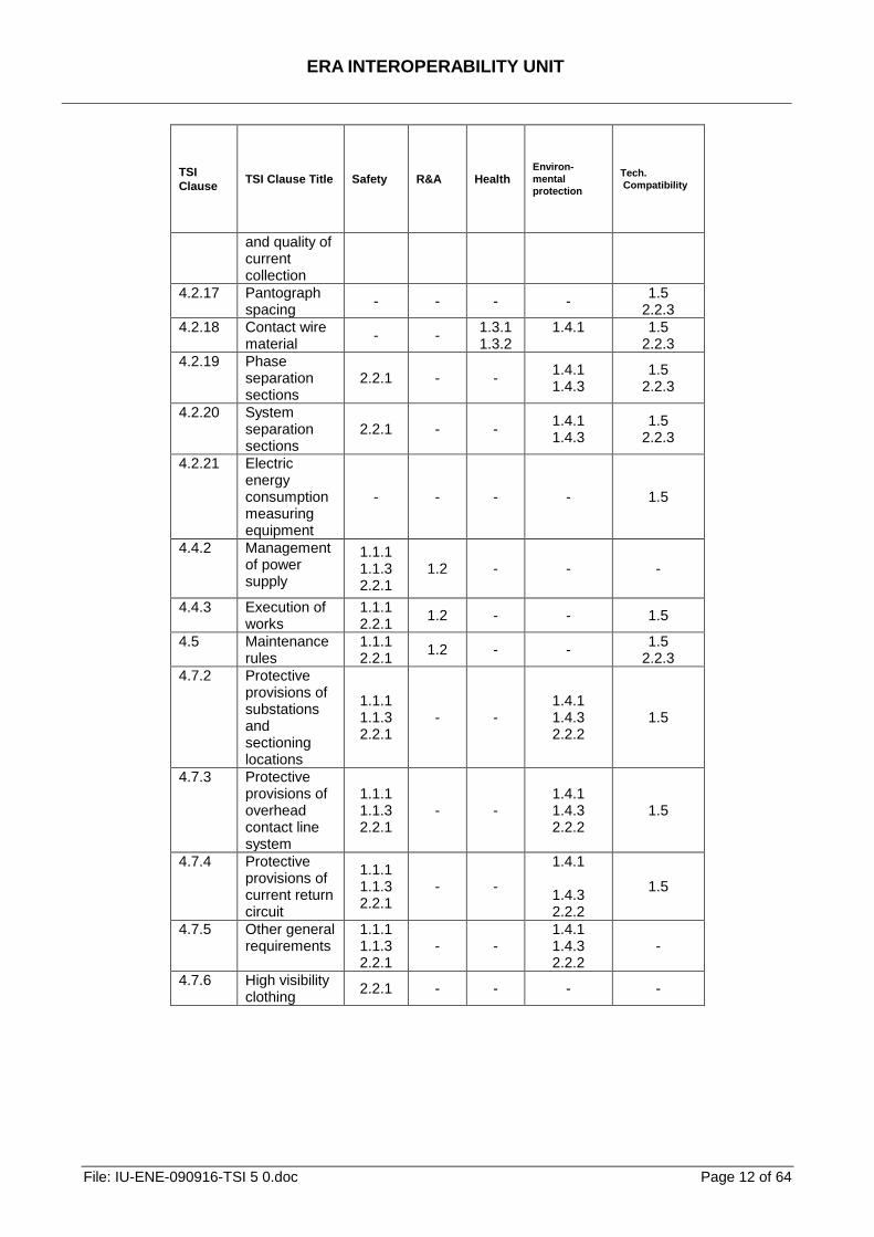
According to Article 4(1) of the Directive 2008/57/EC, the rail system, its subsystems and their interoperability constituents shall fulfil the essential requirements set out in general terms in Annex III of the Directive. The following table indicates basic parameters of this TSI and their correspondence to the essential requirements as explained in Annex III of the Directive.
TSI
Clause TSI Clause Title Safety R&A Health
Environ-
mental
protection
Tech.
Compatibility
4.2.3 Voltage and frequency
- - - - 1.5
2.2.3
4.2.4 Parameters relating to supply system performance
- - - - 1.5
2.2.3
4.2.5 Continuity of power supply in case of disturbances in tunnels
1.1.1 2.2.1
1.2 - - -
4.2.6 Current capacity, DC systems, trains at standstill
- - - - 1.5
2.2.3
4.2.7 Regenerative braking
- - - 1.4.1 1.4.3
1.5 2.2.3
4.2.8 Electrical protection coordination arrangements
2.2.1 - - - 1.5
4.2.9 Harmonics and dynamic effects for AC systems
- - - 1.4.1 1.4.3
1.5
4.2.11 External electromagnetic compatibility
- - 1.4.1 1.4.3 2.2.2
1.5
4.2.12 Protection of the environment
- - - 1.4.1 1.4.3 2.2.2
-
4.2.13 Geometry of the overhead contact line
- - - - 1.5
2.2.3
4.2.14 Pantograph gauge
- - - - 1.5
2.2.3
4.2.15 Mean contact force
- - - - 1.5
2.2.3
4.2.16 Dynamic behaviour
- - - 1.4.1 2.2.2
1.5 2.2.3
ERA INTEROPERABILITY UNIT
File: IU-ENE-090916-TSI 5 0.doc Page 12 of 64
TSI
Clause TSI Clause Title Safety R&A Health
Environ-
mental
protection
Tech.
Compatibility
and quality of current collection
4.2.17 Pantograph spacing
- - - - 1.5
2.2.3
4.2.18 Contact wire material
- - 1.3.1 1.3.2
1.4.1
1.5 2.2.3
4.2.19 Phase separation sections
2.2.1 - - 1.4.1 1.4.3
1.5 2.2.3
4.2.20 System separation sections
2.2.1 - - 1.4.1 1.4.3
1.5 2.2.3
4.2.21 Electric energy consumption measuring equipment
- - - - 1.5
4.4.2 Management of power supply
1.1.1 1.1.3 2.2.1
1.2 - - -
4.4.3 Execution of works
1.1.1 2.2.1
1.2 - - 1.5
4.5 Maintenance rules
1.1.1 2.2.1
1.2 - - 1.5
2.2.3
4.7.2 Protective provisions of substations and sectioning locations
1.1.1 1.1.3 2.2.1
- - 1.4.1 1.4.3 2.2.2
1.5
4.7.3 Protective provisions of overhead contact line system
1.1.1 1.1.3 2.2.1
- - 1.4.1 1.4.3 2.2.2
1.5
4.7.4 Protective provisions of current return circuit
1.1.1 1.1.3 2.2.1
- -
1.4.1
1.4.3 2.2.2
1.5
4.7.5 Other general requirements
1.1.1 1.1.3 2.2.1
- - 1.4.1 1.4.3 2.2.2
-
4.7.6 High visibility clothing
2.2.1 - - - -
ERA INTEROPERABILITY UNIT
File: IU-ENE-090916-TSI 5 0.doc Page 13 of 64
4. Characterisation of the subsystem
4.1. Introduction
The rail system, to which the Directive 2008/57/EC applies, and of which the subsystem is a part, is an integrated system whose consistency shall be verified. This consistency must be checked, in particular, with regard to the specifications of the subsystem, its interfaces vis-à-vis the system in which it is integrated, as well as the operating and maintenance rules.
The functional and technical specifications of the subsystem and its interfaces, described in chapters 4.2 and 4.3, do not impose the use of specific technologies or technical solutions, except where this is strictly necessary for the interoperability of the rail network. But innovative solutions for interoperability may require new specifications and/or new assessment methods. In order to allow technological innovation, these specifications and assessment methods shall be developed by the process described in chapters 6.1.3 and 6.2.3.
Taking account of all the applicable essential requirements, the energy subsystem is characterised by the specifications set out in clauses 4.2 to 4.7. A list of parameters relevant for the energy subsystem which shall be collected in the Register of infrastructure is in Annex C to this TSI.
Procedures for the EC verification of the energy subsystem are indicated in clause 6.2.4 and Annex B, Table B.1, to this TSI.
For Specific Cases, see chapter 7.5;
Where reference is made to EN standards, any variations called "national deviations" or "special national conditions" in the EN do not apply.
4.2. Functional and technical specifications of the subsystem
4.2.1. General provisions
The performance to be achieved by the Energy subsystem shall correspond to the relevant performance of the rail system, with respect to:
o the maximum line speed, type of train and o the power demand of the trains at the pantographs.
4.2.2. Basic parameters characterising the energy subsystem
The basic parameters characterising the energy subsystem are:
Power supply:
o Voltage and frequency (4.2.3) o Parameters relating to supply system performance (4.2.4) o Continuity of power supply in case of disturbances in tunnels (4.2.5) o Current capacity, DC systems, trains at standstill (4.2.6) o Regenerative braking (4.2.7) o Electrical protection coordination arrangements (4.2.8) o Harmonics and dynamic effects for AC systems (4.2.9), and
o Electric energy consumption measuring equipment (4.2.21)
Geometry of the OCL and quality of current collection:
ERA INTEROPERABILITY UNIT
File: IU-ENE-090916-TSI 5 0.doc Page 14 of 64
o Geometry of the overhead contact line (4.2.13) o Pantograph gauge (4.2.14) o Mean contact force (4.2.15) o Dynamic behaviour and quality of current collection (4.2.16) o Pantograph spacing (4.2.17) o Contact wire material (4.2.18) o Phase separation sections (4.2.19), and o System separation sections (4.2.20)
4.2.3. Voltage and frequency
Locomotives and traction units need standardisation of voltage and frequency. The values and limits of the voltage and frequency at the terminals of the substation and at the pantograph shall comply with EN50163:2004, clause 4.
The AC 25 kV 50 Hz system is to be the target supply system, for reasons of compatibility with the electrical generation and distribution systems and standardisation of substation equipment.
However, due to the high investment costs needed to migrate from other system voltages to the 25 kV system and the possibility of using multi-system traction units, the use of the following systems for new, upgraded or renewed subsystems is permitted:
o AC 15 kV 16.7 Hz o DC 3 kV, and o DC 1.5 kV
Nominal voltage and frequency shall be listed in the Register of infrastructure (see Annex C).
4.2.4. Parameters relating to supply system performance
The design of the energy subsystem is determined by the line speed for the planned services and the topography.
Therefore the following parameters have to be taken in consideration:
o the maximum train current o the power factor of trains, and o the mean useful voltage
4.2.4.1. Maximum train current
The Infrastructure Manager shall declare the maximum train current in the Register of infrastructure (see Annex C).
The energy subsystem design shall ensure the ability of the power supply to achieve the specified performance and permit the operation of trains with a power less than 2 MW without current limitation as described in clause 7.3 of EN50388:2005.
4.2.4.2. Power factor of trains
The power factor of trains shall be in accordance with requirements in Annex G and EN50388:2005 clause 6.3.
4.2.4.3. Mean useful voltage
The calculated mean useful voltage ―at the pantograph‖ shall comply with EN50388:2005, clauses 8.3 and 8.4, using the design data for the power factor according to Annex G.
ERA INTEROPERABILITY UNIT
File: IU-ENE-090916-TSI 5 0.doc Page 15 of 64
4.2.5. Continuity of power supply in case of disturbances in tunnels
The power supply and the overhead contact line system shall be designed to enable continuity of operation in case of disturbances in tunnels. This shall be achieved by sectioning overhead contact line in accordance with clause 4.2.3.1 of the CR SRT TSI.
4.2.6. Current capacity, DC systems, trains at standstill
The overhead contact line of DC systems shall be designed to sustain 300 A (for a 1.5 kV supply system) and 200 A (for a 3 kV supply system), per pantograph when the train is at standstill.
This shall be achieved using a static contact force as defined in clause 7.1 of EN50367:2006.
Where the overhead contact line has been designed to sustain higher values for maximum current at standstill, this shall be declared by the Infrastructure Manager in the Register of infrastructure (see Annex C).
The OCL shall be designed taking into account the temperature limits in accordance with EN50119:2009 clause 5.1.2.
4.2.7. Regenerative braking
AC power supply systems shall be designed to permit the use of regenerative braking as a service brake, able to exchange power seamlessly either with other trains or by any other means.
DC power supply systems shall be designed to permit the use of regenerative braking as a service brake at least by exchanging power with other trains.
Information about possibility of the use of regenerative braking shall be provided in the Register of infrastructure (see Annex C).
4.2.8. Electrical protection coordination arrangements
Electrical protection coordination design of the energy subsystem shall comply with the requirements detailed in EN50388:2005, clause 11 except table 8 which is replaced by Annex H of this TSI.
4.2.9. Harmonics and dynamic effects for AC systems
The CR energy subsystem and rolling stock must be able to work together without interference problems, such as over-voltages and other phenomena described in EN50388:2005 clause 10.
4.2.10. Harmonic emissions towards the power utility
Harmonic emissions towards the power utility shall be dealt with by the Infrastructure Manager taking into account European or national standards and the requirements of the power utility.
No conformity assessment is required within this TSI.
4.2.11. External electromagnetic compatibility
External electromagnetic compatibility is not a specific characteristic of the rail network. Energy supply installations shall comply with the Essential Requirements of the EMC Directive 2004/108/EC.
ERA INTEROPERABILITY UNIT
File: IU-ENE-090916-TSI 5 0.doc Page 16 of 64
No conformity assessment is required within this TSI.
4.2.12. Protection of the environment
Protection of the environment is covered by other European legislation concerning the assessment of the effects of certain projects on the environment.
No conformity assessment is required within this TSI.
4.2.13. Geometry of the overhead contact line
Overhead contact line shall be designed for use by pantographs with the head geometry specified in the CR LOC&PAS TSI clause 4.2.8.2.9.2.
The contact wire height, gradient of the contact wire in relation to the track and the lateral deviation of the contact wire under the action of a cross-wind all govern the interoperability of the rail network.
4.2.13.1. Contact wire height
The nominal contact wire height shall be in the range of 5.00 - 5.75 m. For the relation between the contact wire heights and pantograph working heights see EN50119:2009 figure 1.
The contact wire height may be lower in cases related to gauge (like bridges, tunnels). The minimum contact wire height shall be calculated in accordance with EN50119:2009 clause 5.10.4.
The contact wire may be higher in cases e.g. level crossings, loading areas, etc. In these cases the maximum design contact wire height shall not be greater than 6.20 m.
Taking into account tolerances and uplift in accordance with EN50119:2009 figure 1, the maximum contact wire height shall not be greater than 6.50 m.
The nominal contact wire height shall be listed in the Register of infrastructure (see Annex C).
4.2.13.2. Variation in contact wire height
The variation in contact wire height shall fulfil the requirements imposed by EN50119:2009 clause 5.10.3.
The contact wire gradient specified in EN50119:2009 clause 5.10.3 may be exceeded on an exceptional basis where a series of restrictions on the contact wire height e.g. level crossings, bridges, tunnels, prevents compliance; in this case when applying the requirements of clause 4.2.16., only the requirement related to the maximum contact force shall be complied with.
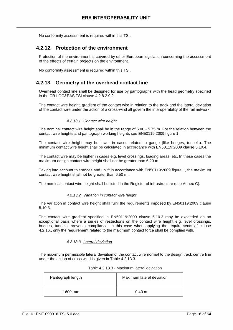
4.2.13.3. Lateral deviation
The maximum permissible lateral deviation of the contact wire normal to the design track centre line under the action of cross wind is given in Table 4.2.13.3.
Table 4.2.13.3 - Maximum lateral deviation
Pantograph length Maximum lateral deviation
1600 mm 0,40 m

ERA INTEROPERABILITY UNIT
File: IU-ENE-090916-TSI 5 0.doc Page 17 of 64
1950 mm 0,55 m
The values shall be adjusted taking into account the movement of the pantograph and track tolerances according to Annex E.
In the case of the multi-rail track, the requirement shall be fulfilled for each pair of rails (designed, to be operated as separated track) that is intended to be assessed against TSI.
The pantograph profiles that are permitted to operate on the route, shall be listed in the Register of infrastructure (see Annex C).
ERA INTEROPERABILITY UNIT
File: IU-ENE-090916-TSI 5 0.doc Page 18 of 64
4.2.14. Pantograph gauge
No part of the energy sub-system shall enter the mechanical kinematic pantograph gauge (see Annex E figure E.2) except for the contact wire and steady arm.
The mechanical kinematic pantograph gauge for interoperable lines is determined using the method shown in Annex E clause E.2 and the pantograph profiles defined in CR LOC&PAS TSI clause 4.2.8.2.9.2.
This gauge shall be calculated using a kinematic method, with values:
- for the pantograph sway - epu - of 0.110 m at the lower verification height - h`u ≤ 5,0 m and
- for the pantograph sway - epo - of 0.170 m at the upper verification height – h`o - 6,5 m,
in accordance with Annex E clause E.2.1.4 and other values in accordance with Annex E clause E.3.
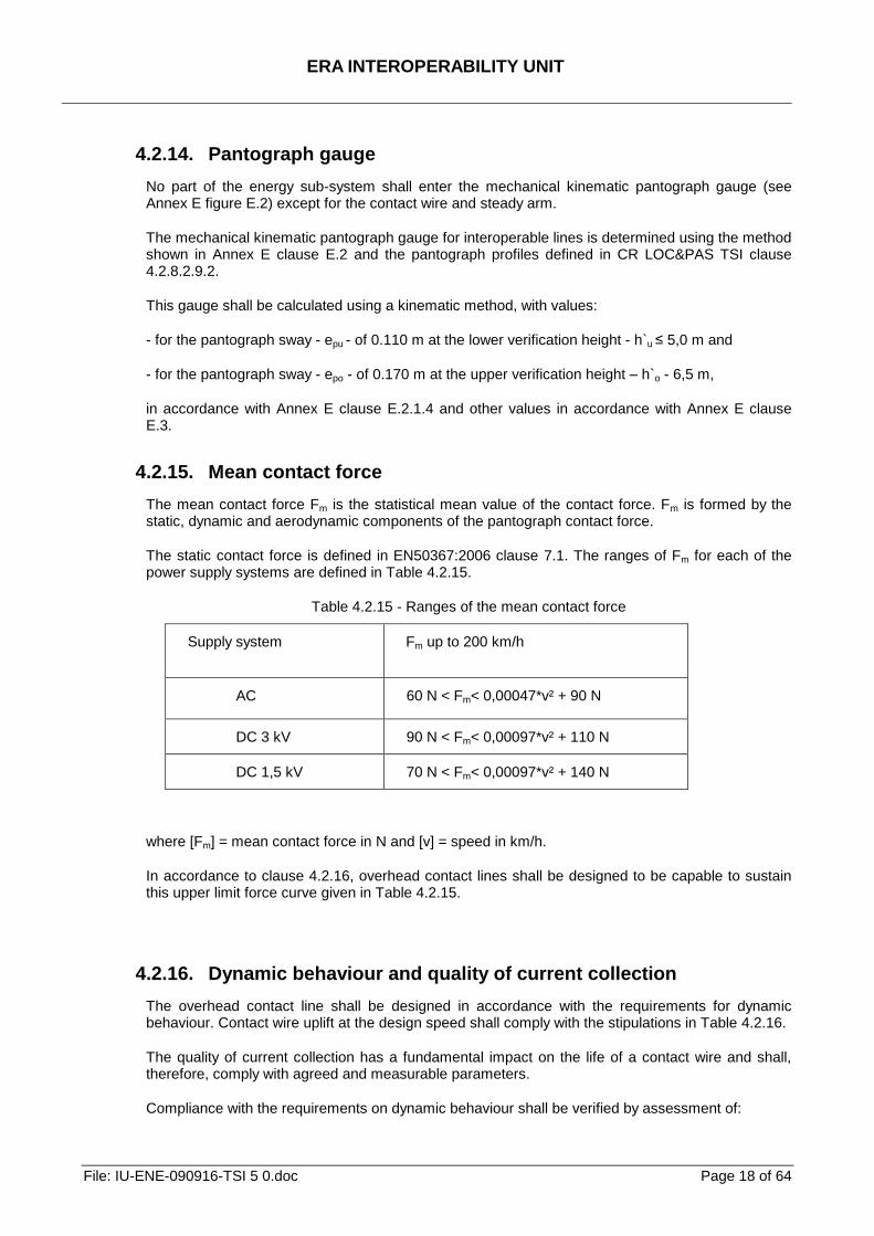
4.2.15. Mean contact force
The mean contact force Fm is the statistical mean value of the contact force. Fm is formed by the static, dynamic and aerodynamic components of the pantograph contact force.
The static contact force is defined in EN50367:2006 clause 7.1. The ranges of Fm for each of the power supply systems are defined in Table 4.2.15.
Table 4.2.15 - Ranges of the mean contact force
Supply system Fm up to 200 km/h
AC 60 N < Fm< 0,00047*v² + 90 N
DC 3 kV 90 N < Fm< 0,00097*v² + 110 N
DC 1,5 kV 70 N < Fm< 0,00097*v² + 140 N
where [Fm] = mean contact force in N and [v] = speed in km/h.
In accordance to clause 4.2.16, overhead contact lines shall be designed to be capable to sustain this upper limit force curve given in Table 4.2.15.
4.2.16. Dynamic behaviour and quality of current collection
The overhead contact line shall be designed in accordance with the requirements for dynamic behaviour. Contact wire uplift at the design speed shall comply with the stipulations in Table 4.2.16.
The quality of current collection has a fundamental impact on the life of a contact wire and shall, therefore, comply with agreed and measurable parameters.
Compliance with the requirements on dynamic behaviour shall be verified by assessment of:
ERA INTEROPERABILITY UNIT
File: IU-ENE-090916-TSI 5 0.doc Page 19 of 64
o Contact wire uplift
and either
o Mean contact force Fm and standard deviation σmax
or
o Percentage of arcing
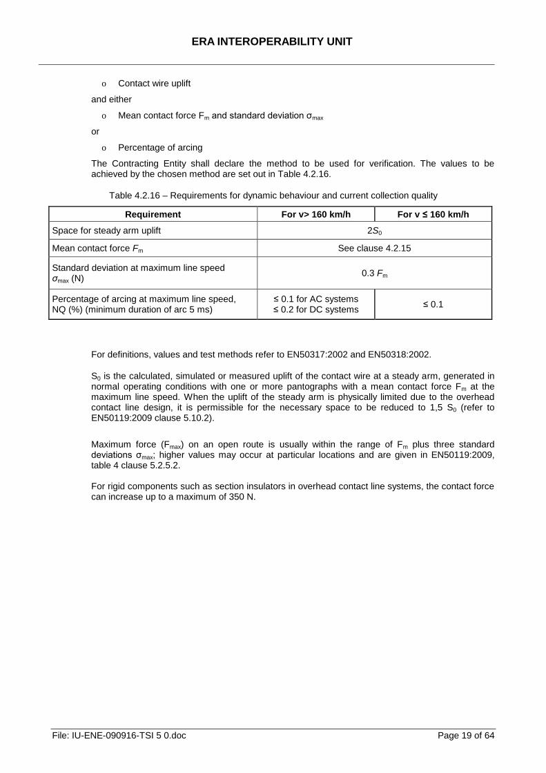
The Contracting Entity shall declare the method to be used for verification. The values to be achieved by the chosen method are set out in Table 4.2.16.
Table 4.2.16 – Requirements for dynamic behaviour and current collection quality
Requirement For v> 160 km/h For v ≤ 160 km/h
Space for steady arm uplift 2S0
Mean contact force Fm See clause 4.2.15
Standard deviation at maximum line speed σmax (N)
0.3 Fm
Percentage of arcing at maximum line speed, NQ (%) (minimum duration of arc 5 ms)
≤ 0.1 for AC systems ≤ 0.2 for DC systems
≤ 0.1
For definitions, values and test methods refer to EN50317:2002 and EN50318:2002.
S0 is the calculated, simulated or measured uplift of the contact wire at a steady arm, generated in normal operating conditions with one or more pantographs with a mean contact force Fm at the maximum line speed. When the uplift of the steady arm is physically limited due to the overhead contact line design, it is permissible for the necessary space to be reduced to 1,5 S0 (refer to EN50119:2009 clause 5.10.2).
Maximum force (Fmax) on an open route is usually within the range of Fm plus three standard deviations σmax; higher values may occur at particular locations and are given in EN50119:2009, table 4 clause 5.2.5.2. For rigid components such as section insulators in overhead contact line systems, the contact force can increase up to a maximum of 350 N.
ERA INTEROPERABILITY UNIT
File: IU-ENE-090916-TSI 5 0.doc Page 20 of 64
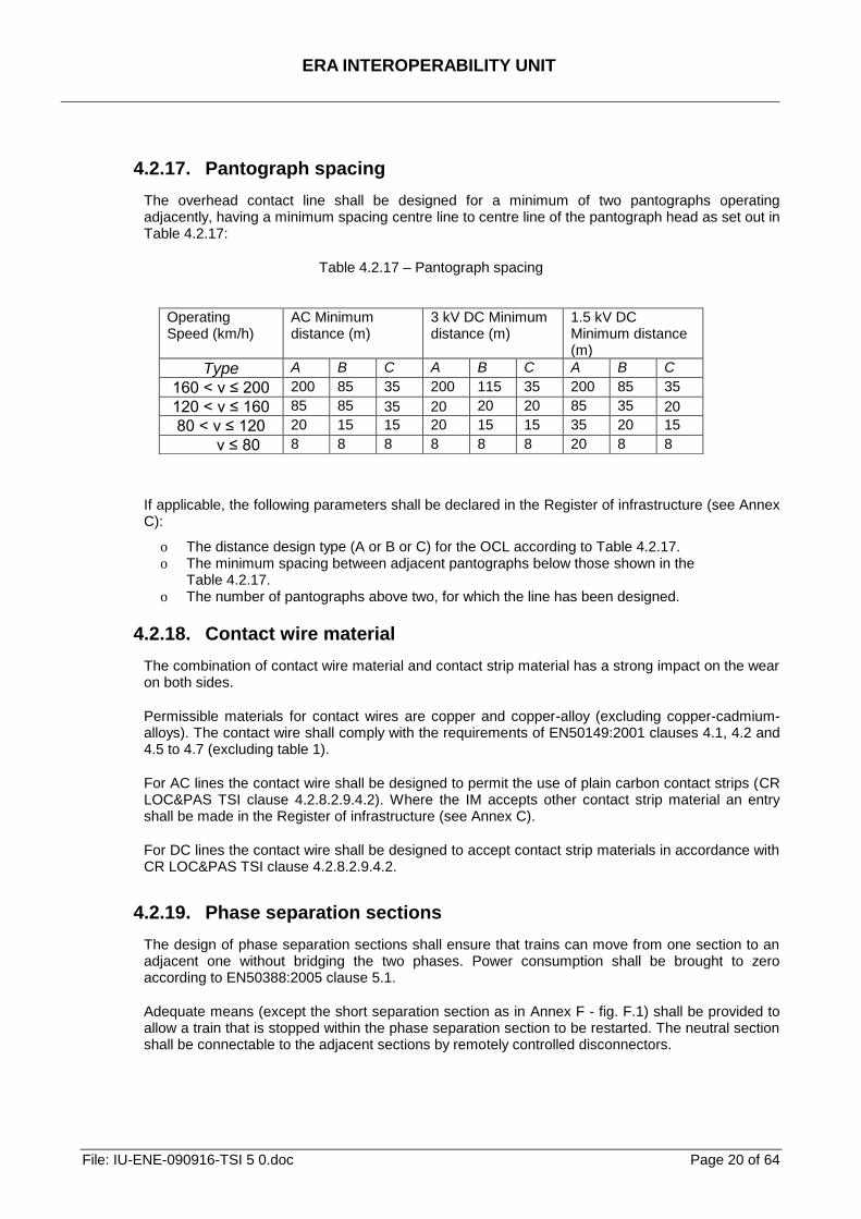
4.2.17. Pantograph spacing
The overhead contact line shall be designed for a minimum of two pantographs operating adjacently, having a minimum spacing centre line to centre line of the pantograph head as set out in Table 4.2.17:
Table 4.2.17 – Pantograph spacing
If applicable, the following parameters shall be declared in the Register of infrastructure (see Annex C):
o The distance design type (A or B or C) for the OCL according to Table 4.2.17. o The minimum spacing between adjacent pantographs below those shown in the
Table 4.2.17. o The number of pantographs above two, for which the line has been designed.
4.2.18. Contact wire material
The combination of contact wire material and contact strip material has a strong impact on the wear on both sides.
Permissible materials for contact wires are copper and copper-alloy (excluding copper-cadmium-alloys). The contact wire shall comply with the requirements of EN50149:2001 clauses 4.1, 4.2 and 4.5 to 4.7 (excluding table 1).
For AC lines the contact wire shall be designed to permit the use of plain carbon contact strips (CR LOC&PAS TSI clause 4.2.8.2.9.4.2). Where the IM accepts other contact strip material an entry shall be made in the Register of infrastructure (see Annex C).
For DC lines the contact wire shall be designed to accept contact strip materials in accordance with CR LOC&PAS TSI clause 4.2.8.2.9.4.2.
4.2.19. Phase separation sections
The design of phase separation sections shall ensure that trains can move from one section to an adjacent one without bridging the two phases. Power consumption shall be brought to zero according to EN50388:2005 clause 5.1.
Adequate means (except the short separation section as in Annex F - fig. F.1) shall be provided to allow a train that is stopped within the phase separation section to be restarted. The neutral section shall be connectable to the adjacent sections by remotely controlled disconnectors.
Operating Speed (km/h)
AC Minimum distance (m)
3 kV DC Minimum distance (m)
1.5 kV DC Minimum distance (m)
Type A B C A B C A B C
160 < v ≤ 200 200 85 35 200 115 35 200 85 35
120 < v ≤ 160 85 85 35 20 20 20 85 35 20
80 < v ≤ 120 20 15 15 20 15 15 35 20 15
v ≤ 80 8 8 8 8 8 8 20 8 8
ERA INTEROPERABILITY UNIT
File: IU-ENE-090916-TSI 5 0.doc Page 21 of 64
The design of separation sections shall normally adopt solutions as described in EN50367:2006 Annex A.1 or in Annex F of this TSI. Where an alternative solution is proposed, it shall be demonstrated that the alternative is at least as reliable.
Information on the design of phase separation sections and permissible configuration of raised pantographs shall be provided in the Register of infrastructure (see Annex C).
4.2.20. System separation sections
4.2.20.1. General
The design of system separation sections shall ensure that vehicles can move from one power supply system to an adjacent different power supply system without bridging the two systems. A system separation between AC and DC system needs additional measures to be taken in the return circuit as defined in EN50122-2:1998, clause 6.1.1.
There are two methods for traversing system separation sections:
a. with pantograph raised and touching the contact wire,
b. with pantograph lowered and not touching the contact wire.
The neighbouring Infrastructure Managers shall agree either (a) or (b) according to the prevailing circumstances. The method to be adopted shall be recorded in the Register of infrastructure (see Annex C).
4.2.20.2. Pantographs raised
If system separation sections are traversed with pantographs raised to the contact wire, their functional design is specified as follows:
o the geometry of different elements of the overhead contact line shall prevent pantographs short-circuiting or bridging both power systems.
o provision shall be made in the energy subsystem to avoid bridging of both adjacent power supply systems should the opening of the on-board circuit breaker(s) fail,
o variation in contact wire height along the entire separation section shall fulfil requirements set in EN50119:2009 clause 5.2.10.
The pantograph arrangements that are permitted to traverse the system separation with pantographs raised shall be provided in the Register of infrastructure (see Annex C).
4.2.20.3. Pantographs lowered
This option shall be chosen if the conditions of operation with pantographs raised cannot be met.
If a system separation section is traversed with pantographs lowered, it shall be designed so as to avoid the bridging by an unintentionally raised pantograph. Equipment shall be provided to switch off both power supply systems should a pantograph remain raised, e.g. by detection of short circuits.
4.2.21. Electric energy consumption measuring equipment
As it is specified in clause 2.1 of this TSI, requirements for the on-board electric energy consumption measuring equipment are set out in the CR LOC&PAS TSI.
The use of electric energy consumption measuring equipment is not mandatory.
ERA INTEROPERABILITY UNIT
File: IU-ENE-090916-TSI 5 0.doc Page 22 of 64
If an electric energy consumption measuring equipment is required for billing purposes, it shall be compatible with CR LOC&PAS TSI clause 4.2.8.2.8 and data provided by this system shall be accepted for billing.
ERA INTEROPERABILITY UNIT
File: IU-ENE-090916-TSI 5 0.doc Page 23 of 64
4.3. Functional and technical specifications of the interfaces
4.3.1. General requirements
From the standpoint of technical compatibility, the interfaces are listed in subsystem order as follows: rolling stock, infrastructure, control and command and signalling, traffic operation and management. They also include indications to safety in railway tunnels TSI (SRT TSI).
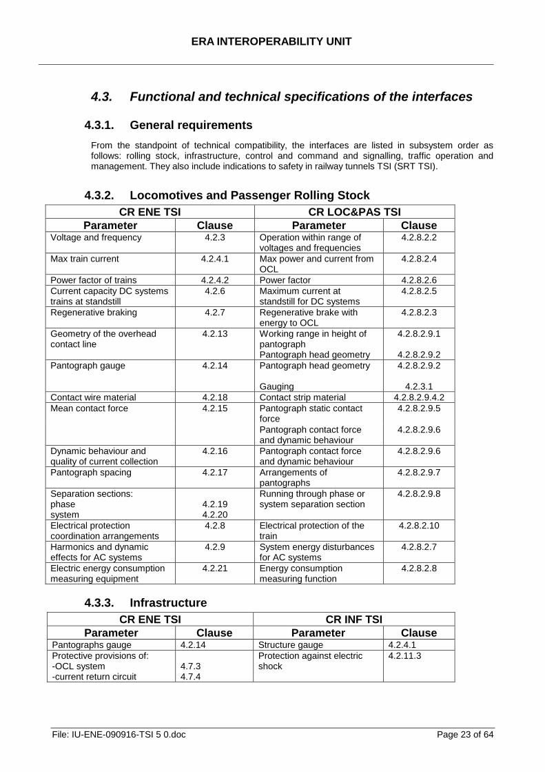
4.3.2. Locomotives and Passenger Rolling Stock
CR ENE TSI CR LOC&PAS TSI
Parameter Clause Parameter Clause Voltage and frequency
4.2.3 Operation within range of voltages and frequencies
4.2.8.2.2
Max train current 4.2.4.1 Max power and current from OCL
4.2.8.2.4
Power factor of trains 4.2.4.2 Power factor 4.2.8.2.6
Current capacity DC systems trains at standstill
4.2.6 Maximum current at standstill for DC systems
4.2.8.2.5
Regenerative braking 4.2.7 Regenerative brake with energy to OCL
4.2.8.2.3
Geometry of the overhead contact line
4.2.13 Working range in height of pantograph Pantograph head geometry
4.2.8.2.9.1
4.2.8.2.9.2
Pantograph gauge 4.2.14 Pantograph head geometry Gauging
4.2.8.2.9.2
4.2.3.1
Contact wire material 4.2.18 Contact strip material 4.2.8.2.9.4.2
Mean contact force 4.2.15 Pantograph static contact force
4.2.8.2.9.5
Pantograph contact force and dynamic behaviour
4.2.8.2.9.6
Dynamic behaviour and quality of current collection
4.2.16 Pantograph contact force and dynamic behaviour
4.2.8.2.9.6
Pantograph spacing 4.2.17 Arrangements of pantographs
4.2.8.2.9.7
Separation sections: phase system
4.2.19 4.2.20
Running through phase or system separation section
4.2.8.2.9.8
Electrical protection coordination arrangements
4.2.8 Electrical protection of the train
4.2.8.2.10
Harmonics and dynamic effects for AC systems
4.2.9 System energy disturbances for AC systems
4.2.8.2.7
Electric energy consumption measuring equipment
4.2.21 Energy consumption measuring function
4.2.8.2.8
4.3.3. Infrastructure
CR ENE TSI CR INF TSI
Parameter Clause Parameter Clause Pantographs gauge 4.2.14 Structure gauge 4.2.4.1
Protective provisions of: -OCL system -current return circuit
4.7.3 4.7.4
Protection against electric shock
4.2.11.3
ERA INTEROPERABILITY UNIT
File: IU-ENE-090916-TSI 5 0.doc Page 24 of 64
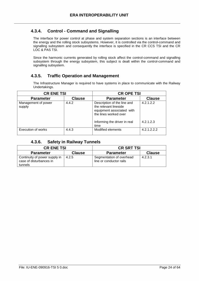
4.3.4. Control - Command and Signalling
The interface for power control at phase and system separation sections is an interface between the energy and the rolling stock subsystems. However, it is controlled via the control-command and signalling subsystem and consequently the interface is specified in the CR CCS TSI and the CR LOC & PAS TSI.
Since the harmonic currents generated by rolling stock affect the control-command and signalling subsystem through the energy subsystem, this subject is dealt within the control-command and signalling subsystem.
4.3.5. Traffic Operation and Management
The Infrastructure Manager is required to have systems in place to communicate with the Railway Undertakings.
CR ENE TSI CR OPE TSI
Parameter Clause Parameter Clause Management of power supply
4.4.2 Description of the line and the relevant lineside equipment associated with the lines worked over Informing the driver in real time
4.2.1.2.2 4.2.1.2.3
Execution of works 4.4.3 Modified elements 4.2.1.2.2.2
4.3.6. Safety in Railway Tunnels
CR ENE TSI CR SRT TSI
Parameter Clause Parameter Clause Continuity of power supply in case of disturbances in tunnels
4.2.5 Segmentation of overhead line or conductor rails
4.2.3.1
ERA INTEROPERABILITY UNIT
File: IU-ENE-090916-TSI 5 0.doc Page 25 of 64
4.4. Operating rules
4.4.1. Introduction
To meet the essential requirements in Chapter 3, the operating rules specific to the subsystem concerned by this TSI are as follows:
4.4.2. Management of power supply
4.4.2.1. Management of power supply under normal conditions
Under normal conditions in order to conform to clause 4.2.4.1, the maximum permissible train current shall not exceed the value contained in the Register of Infrastructure (see Annex C).
4.4.2.2. Management of power supply under abnormal conditions
Under abnormal conditions the maximum permissible train current (see Annex C) can be lower. The Infrastructure Manager shall give notice of the variation to the Railway Undertakings.
4.4.2.3. Management of power supply in case of danger
Procedures shall be implemented by the Infrastructure Manager to manage the power supply adequately in an emergency. Railway undertakings operating and companies working on the line shall be given notice of the temporary measures, of their geographic location, their nature and the means of signalling. The responsibility for earthing shall be defined in the emergency plan to be written by the Infrastructure Manager. Conformity assessment shall be carried out by checking the existence of communications channels, instructions, procedures and devices to be used in emergency.
4.4.3. Execution of works
In certain situations involving pre-planned works, it may be necessary to temporarily suspend the specifications of the energy subsystem and its interoperability constituents defined in chapters 4 and 5 of the TSI. In this case, the Infrastructure Manager shall define the appropriate exceptional operating conditions needed to ensure safety.
The following general provisions apply:
o the exceptional operating conditions not complying with the TSIs shall be temporary and planned,
o railway undertakings operating and companies working on the line shall be given notice of these temporary exceptions, of their geographic location, their nature and the means of indication.
4.5. Maintenance rules
The specified characteristics of the power supply system (including substations and sectioning locations) and the overhead contact line shall be upheld during their lifetime.
A maintenance plan shall be drawn up to ensure that the specified characteristics of the energy subsystem required to assure interoperability are upheld within the specified limits. The maintenance plan shall contain in particular the description of professional competences for the staff and of the personal protective safety equipment to be used by it.
ERA INTEROPERABILITY UNIT
File: IU-ENE-090916-TSI 5 0.doc Page 26 of 64
Maintenance procedures shall not downgrade safety provisions such as the continuity of return current circuit, limitation of overvoltages and detection of short circuits.
4.6. Professional qualifications
The IM is responsible for the professional qualifications and competence of the staff which operates and controls the energy subsystem; the IM has to ensure that the processes for competence assessment are clearly documented. The competence requirements for the maintenance of the energy subsystem shall be detailed in the maintenance plan (see clause 4.5).
4.7. Health and safety conditions
4.7.1. Introduction
The health and safety conditions of staff required for the operation and maintenance of the energy subsystem and for the implementation of the TSI, are described in the following clauses.
4.7.2. Protective provisions of substations and sectioning locations
Electrical safety of the traction power supply systems’ shall be achieved by designing and testing these installations according to EN50122-1:1997, clauses 8 (excluding reference to EN50179) and 9.1. Substations and sectioning locations shall be barred against unauthorised access.
The earthing of substations and sectioning locations shall be integrated into the general earthing system along the route.
For each installation, it shall be demonstrated that return current circuits and earthing conductors are adequate by design review. It shall be demonstrated that the provisions for protection against electric shock and rail potential, as designed, have been installed.
4.7.3. Protective provisions of overhead contact line system
Electrical safety of the overhead contact line system and protection against electric shock shall be achieved by compliance with EN50119:2009 clause 4.3 and EN50122-1:1997 clauses 4.1, 4.2, 5.1, 5.2 and 7, excluding requirements for connections for track circuits.
The earthing provisions of the overhead contact line system shall be integrated into the general earthing system along the route.
For each installation, it shall be demonstrated that earthing conductors are adequate, by design review. It shall be demonstrated that the provisions for protection against electric shock and rail potential, as designed, have been installed.
4.7.4. Protective provisions of current return circuit
Electrical safety and functionality of the current return circuit shall be achieved by designing these installations according to EN50122-1:1997, clauses 7 and 9.2 to 9.6 (excluding reference to EN 50179).
For each installation it shall be demonstrated that return current circuits are adequate by design review. It shall also be demonstrated that the provisions for protection against electric shock and rail potential, as designed, have been installed.
ERA INTEROPERABILITY UNIT
File: IU-ENE-090916-TSI 5 0.doc Page 27 of 64
4.7.5. Other general requirements
In addition to clauses 4.7.2 to 4.7.4, and the requirements specified in the maintenance plan (see clause 4.5), precautions shall be taken to ensure health and safety for maintenance and operations staff, in accordance with the European regulations and the national regulations that are compatible with European legislation.
4.7.6. High Visibility Clothing
Staff engaged in the maintenance of the energy subsystem, when working on or near the track, shall wear reflective clothes, which bear the CE mark (and therefore satisfy the provisions of Directive 89/686/EEC of 21 December 1989 on the approximation of the laws of the Member States relating to personal protective equipment).
4.8. Register of Infrastructure and Register of rolling stock
4.8.1. Introduction
In accordance with Articles 33 and 35 of the Directive 2008/57/EC, each TSI shall indicate precisely the information that must be included in the Register of rolling stock and Register of Infrastructure.
4.8.2. Register of infrastructure
Annex C of this TSI indicates which information concerning the energy subsystem shall be included in the Register of infrastructure. In all cases when any part or whole of an energy subsystem is made compliant with this TSI, an entry shall be made in the Register of Infrastructure as indicated in Annex C and the relevant clause in chapters 4 and 7.5 (specific cases).
4.8.3. Register of rolling stock
Annex D of this TSI indicates which information concerning the energy subsystem shall be included in the Register of rolling stock.
ERA INTEROPERABILITY UNIT
File: IU-ENE-090916-TSI 5 0.doc Page 28 of 64
5. Interoperability constituents
5.1. List of constituents The interoperability constituents are covered by the relevant provisions of the Directive 2008/57/EC, and are listed below so far as the energy subsystem is concerned.
Overhead contact line: The Interoperability Constituent overhead contact line consists of the components listed below to be installed within an energy subsystem, and the associated design and configuration rules.
The components of an overhead contact line are an arrangement of wire(s) suspended over the railway line for supplying electricity to electric trains, together with associated fittings, in-line insulators and other attachments including feeders and jumpers. It is placed above the upper limit of the vehicle gauge, supplying vehicles with electrical energy through pantographs.
The supporting components such as cantilevers, masts and foundations, return conductors, auto-transformer feeders, switches and other insulators are not part of the interoperability constituent overhead contact line. They are covered by subsystem requirements so far as interoperability is concerned.
The conformity assessment shall cover the phases and characteristics as indicated in clause 6.1.3 and by X in the Table A.1 of Annex A to this TSI.
ERA INTEROPERABILITY UNIT
File: IU-ENE-090916-TSI 5 0.doc Page 29 of 64
5.2. Constituents' performances and specifications
5.2.1. Overhead contact line
5.2.1.1. Geometry of the OCL
The design of the overhead contact line shall comply with clause 4.2.13.
5.2.1.2. Mean contact force
The overhead contact line shall be designed by using the mean contact force Fm stipulated in clause 4.2.15.
5.2.1.3. Dynamic behaviour
Requirements for dynamic behaviour of the overhead contact line are set out in clause 4.2.16
5.2.1.4. Space for uplift
The overhead contact line shall be designed providing the required space for uplift as set out in clause 4.2.16
5.2.1.5. Design for pantograph spacing
The overhead contact line shall be designed for a pantograph spacing as specified in clauses 4.2.17.
5.2.1.6. Current at standstill
For DC systems, the overhead contact line shall be designed for the requirements set out in clause 4.2.6.
5.2.1.7. Contact wire material
The contact wire material shall comply with the requirements set out in clause 4.2.18.
ERA INTEROPERABILITY UNIT
File: IU-ENE-090916-TSI 5 0.doc Page 30 of 64
6. Assessment of conformity of the interoperability
constituents and EC verification of the subsystems
6.1. Interoperability Constituents
6.1.1. Conformity assessment procedures
The conformity assessment procedures of interoperability constituents as defined in chapter 5 of this TSI shall be carried out by application of modules as specified in EC Decision xxx.
Assessment procedures for particular requirements for interoperability constituent are set out in clause 6.1.4
6.1.2. Application of modules
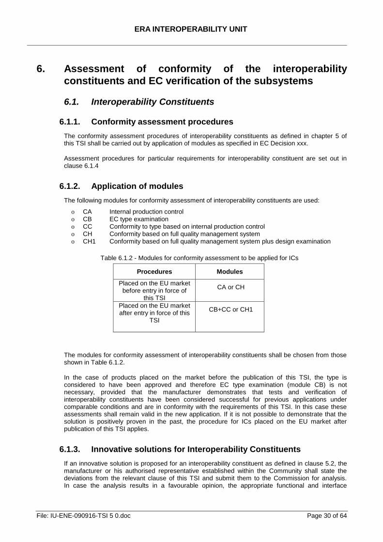
The following modules for conformity assessment of interoperability constituents are used:
o CA Internal production control o CB EC type examination o CC Conformity to type based on internal production control o CH Conformity based on full quality management system o CH1 Conformity based on full quality management system plus design examination
Table 6.1.2 - Modules for conformity assessment to be applied for ICs
Procedures Modules
Placed on the EU market before entry in force of
this TSI
CA or CH
Placed on the EU market after entry in force of this
TSI
CB+CC or CH1
The modules for conformity assessment of interoperability constituents shall be chosen from those shown in Table 6.1.2.
In the case of products placed on the market before the publication of this TSI, the type is considered to have been approved and therefore EC type examination (module CB) is not necessary, provided that the manufacturer demonstrates that tests and verification of interoperability constituents have been considered successful for previous applications under comparable conditions and are in conformity with the requirements of this TSI. In this case these assessments shall remain valid in the new application. If it is not possible to demonstrate that the solution is positively proven in the past, the procedure for ICs placed on the EU market after publication of this TSI applies.
6.1.3. Innovative solutions for Interoperability Constituents
If an innovative solution is proposed for an interoperability constituent as defined in clause 5.2, the manufacturer or his authorised representative established within the Community shall state the deviations from the relevant clause of this TSI and submit them to the Commission for analysis. In case the analysis results in a favourable opinion, the appropriate functional and interface
ERA INTEROPERABILITY UNIT
File: IU-ENE-090916-TSI 5 0.doc Page 31 of 64
specifications for the constituent and the assessment method will be developed under the authorisation of the Commission.
The appropriate functional and interface specifications and the assessment methods so produced shall be incorporated in the TSI by the revision process.
By the notification of a decision of the Commission, taken in accordance with Article 29 of the Directive, the innovative solution may be permitted to be used before being incorporated into the TSI by the revision process.
6.1.4. Particular assessment procedure for Interoperability
Constituent - OCL
6.1.4.1. Assessment of dynamic behaviour and quality of current collection
The assessment of the dynamic behaviour and the quality of the current collection involves the overhead contact line (energy subsystem) and the pantograph (rolling stock subsystem). A new design of overhead contact line shall be assessed by simulation according to EN50318:2002 and by measurement of a test section of the new design according to EN50317:2002. For the purposes of simulation and analysis of the results, representative features (for example tunnels, crossovers, neutral sections etc.) shall be taken into account. The simulations shall be made using at least two different TSI compliant
1 types of pantograph for
the appropriate speed2 and supply system, up to the design speed of the proposed Interoperability
Constituent overhead contact line. It is permitted to perform the simulation using types of pantograph that are under the process of IC certification, provided that they fulfill the other requirements of CR LOC&PAS TSI. The simulation shall be performed for single pantograph and multiple pantographs with spacing according to the requirements set in clause 4.2.17. In order to be acceptable, the simulated current collection quality shall be in accordance with clause 4.2.16 for uplift, mean contact force and standard deviation for each of the pantographs. If the simulation results are acceptable, a site dynamic test with a representative section of the new overhead contact line shall be undertaken. For the above mentioned site test, one of the two types of the pantograph chosen for the simulation, shall be installed on a rolling stock that allows the appropriate speed on the representative section. The tests shall be performed at least for the worst case arrangements of the pantographs derived from the simulations and shall fulfill the requirements set out in clause 4.2.17. Each pantograph shall produce a mean contact force up to the envisaged design speed of the OCL under test as required by clause 4.2.15. In order to be acceptable, the measured current collection quality shall be in accordance with clause 4.2.16, for uplift, and either mean contact force and standard deviation or percentage of arcing. If all the above assessments are passed successfully, the tested overhead contact line design shall be considered to be compliant and may be used on lines where the characteristics of the design are compatible.
Assessment of dynamic behaviour and quality of current collection for interoperability constituent pantograph are set out in clause 6.1.2.2.6 of CR LOC&PAS TSI
6.1.4.2. Assessment of current at standstill
The conformity assessment shall be carried out in accordance with EN50367:2006, Annex A.4.1.
1 i.e. pantographs certificated as Interoperability Constituent according to CR or HS TSIs.
2 i.e. the speed of the two types of pantograph shall be at least equal to the design speed of the simulated overhead contact line.
ERA INTEROPERABILITY UNIT
File: IU-ENE-090916-TSI 5 0.doc Page 32 of 64
6.1.5. EC declaration of conformity of Interoperability Constituents
According to Annex IV clause 3 of the Directive 2008/57/EC, the EC declaration of conformity shall be accompanied by statement setting out the condition of use:
o nominal voltage and frequency; o maximum design speed.
6.2. Energy subsystem
6.2.1. General provisions
At the request of the applicant, the Notified Body carries out EC verification in accordance with Annex VI to the Directive 2008/57/EC, and in accordance with the provisions of the relevant modules as specified in EC Decision xxx.
If the applicant demonstrates that tests or verifications of an energy subsystem have been successful for previous applications of a design in similar circumstances, the Notified Body shall take these tests and verifications into account for the EC verification.
Assessment procedures for particular requirements for subsystem are set out in clause 6.2.4
The applicant shall draw up the EC declaration of verification for the energy subsystem in accordance with Article 18(1) of and Annex V to the Directive 2008/57/EC.
6.2.2. Application of modules
For the EC verification procedure of the energy subsystem the applicant or its authorised representative established within the Community may choose either:
o Module SG: EC verification based on unit verification, or o Module SH1: EC verification based on full quality management system plus design
examination.
6.2.2.1. Application of module SG
In case of module SG, the Notified Body may take into account evidence of examinations, checking or tests that have been successfully performed, under comparable conditions by other bodies1 or by (or on behalf of) the applicant.
6.2.2.1. Application of module SH1
The module SH1 may be chosen only where the activities contributing to the proposed subsystem to be verified (design, manufacturing, assembling, installation) are subject to a quality management system for design, production, final product inspection and testing, approved and surveyed by a Notified Body.
6.2.3. Innovative solutions
If the subsystem includes an innovative solution as defined in clause 4.1, the applicant shall state the deviation from the relevant clauses of the TSI and submit them to the Commission.
In case of favourable opinion, the appropriate functional and interface specifications, and the assessment methods for this solution will be developed.
1 The conditions to trust checking and tests must be similar to the conditions respected by a Notified Body to subcontract activities (see §6.5 of the
Blue Guide on the New Approach).
ERA INTEROPERABILITY UNIT
File: IU-ENE-090916-TSI 5 0.doc Page 33 of 64
The appropriate functional and interface specifications and the assessment methods so produced shall then be incorporated in the TSI by the revision process. By the notification of a decision of the Commission, taken in accordance with Article 29 of the Directive, the innovative solution may be permitted to be used before being incorporated into the TSI by the revision process.
6.2.4. Particular assessment procedures for Subsystem
6.2.4.1. Assessment of mean useful voltage
The assessment shall be carried out in accordance with EN50388:2005, clauses 14.4.1, 14.4.2 (simulation only) and 14.4.3.
6.2.4.2. Assessment of regenerative braking
The assessment for AC power supply fixed installations shall be carried out according to EN50388:2005, clause 14.7.2.
The assessment for DC power supply shall be carried out by a design review.
6.2.4.3. Assessment of electrical protection coordination arrangements
The assessment shall be carried out for design and operation of substations in accordance with EN50388:2005 clause 14.6.
6.2.4.4. Assessment of harmonic and dynamic effects for AC systems
The assessment, based on a compatibility study, shall be conducted according to EN50388:2005 clause 10.3 taking into account over-voltages given in EN 50388:2005 clause 10.4.
6.2.4.5. Assessment of dynamic behaviour and quality of current collection (integration into a subsystem)
If the overhead contact line to be installed on a new line is certificated as an Interoperability Constituent, measurements of the interaction parameters in accordance with EN50317:2002 shall be used to check the correct installation. These measurements shall be carried out with an Interoperability Constituent pantograph, exhibiting the mean contact force characteristics as required by clause 4.2.15 of this TSI for the envisaged design speed of the overhead contact line. The main goal of this test is to identify construction errors but not to assess the design in principle. The installed overhead contact line can be accepted if the measurement results comply with the requirements in clause 4.2.16 for uplift, and either mean contact force and standard deviation or percentage of arcing. Assessment of dynamic behaviour and quality of current collection for integration of the pantograph into rolling stock subsystem are set out in clause 6.2.2.2.14 of CR LOC&PAS TSI
6.2.4.6. Assessment of maintenance plan
The assessment shall be carried out by verifying the existence of the maintenance.
The Notified Body is not responsible for assessing the suitability of the detailed requirements set out in the plan.
ERA INTEROPERABILITY UNIT
File: IU-ENE-090916-TSI 5 0.doc Page 34 of 64
6.3. Sub-system containing Interoperability Constituents not holding an EC declaration
6.3.1. General
For a limited period of time, known as the ―transition period”, it is permissible to issue an EC certificate of verification for a subsystem that contains interoperability constituents not holding an EC Declaration of conformity or suitability for use, on the condition that the provisions described in this section are met.
6.3.2. The transition period
The transition period shall commence from the entry into force of this TSI and shall last for six years.
The production or upgrade/renewal of the subsystem with use of the non-certified ICs must be completed within the transition period.
Once the transition period has ended, and with the exceptions allowed under clause 6.3.3.3 below, interoperability constituents shall be covered by the required EC declaration of conformity and/or suitability for use before being incorporated into the subsystem.
6.3.3. The certification of subsystems containing non-certified
Interoperability Constituents during the transition period
6.3.3.1. Conditions
During the transition period a Notified Body is permitted to issue an EC certificate of verification for a subsystem, even if some of the interoperability constituents incorporated within the subsystem are not covered by the relevant EC declarations of conformity and/or suitability for use according to this TSI, if the following criteria are complied with:
o the conformity of the subsystem has been checked against the requirements of Chapter 4 and in relation to chapter 6.2. to 7 (except ―Specific Cases‖) of this TSI by the Notified Body. Furthermore the conformity of the ICs to chapter 5 and 6.1 does not apply, and
o the interoperability constituents, which are not covered by the relevant EC declaration of conformity and/or suitability for use, have been used in a subsystem already approved and put in service in at least one of the Member State before the entry in force of this TSI.
EC Declarations of conformity and/or suitability for use shall not be drawn up for the interoperability constituents assessed in this manner.
6.3.3.2. Documentation
The EC certificate of verification of the subsystem shall indicate clearly which interoperability constituents have been assessed by the Notified Body as part of the subsystem verification.
The EC declaration of verification of the subsystem shall indicate clearly:
o Which interoperability constituents have been assessed as part of the subsystem o Confirmation that the subsystem contains the interoperability constituents identical to those
verified as part of the subsystem. o For those interoperability constituents, the reason(s) why the manufacturer did not provide an
EC declaration of conformity and/or suitability for use before its incorporation into the subsystem.
ERA INTEROPERABILITY UNIT
File: IU-ENE-090916-TSI 5 0.doc Page 35 of 64
6.3.3.3. Maintenance of the subsystems certified according to 6.3.3.1
During the transition period as well as after the transition period has ended, until the subsystem is upgraded, renewed (taking into account the decision of Member State on application of TSIs), under the responsibility of the body responsible for maintenance, the interoperability constituents which do not hold an EC Declaration of conformity and/or suitability for use and of the same type are permitted to be used as maintenance related replacements (spare parts) for the subsystem. In any case the body responsible for maintenance must ensure that the components for maintenance related replacements are suitable for their applications, are used within their area of use, and enable interoperability to be achieved within the rail system while at the same time meeting the essential requirements.
6.3.3.4. Monitoring arrangements
During the transition period Member States shall:
o Ensure that, where a subsystem is presented for authorization, reasons for non-certification of the interoperability constituent by the manufacturer are identified;
o Notify, to the Commission and to the other Member States, the details of the non-certified IC and the reasons for non-certification.
ERA INTEROPERABILITY UNIT
File: IU-ENE-090916-TSI 5 0.doc Page 36 of 64
7. Implementation
7.1. General
The Member State shall specify for TEN lines those parts of the energy subsystem, which are required for interoperable services (e.g. overhead contact line over tracks, sidings, stations, marshalling yards) and therefore need to comply with this TSI. In specifying these elements the Member State shall consider the coherence of the system as a whole.
7.2. Progressive strategy towards interoperability
7.2.1. Introduction
The strategy described in this TSI applies to new, upgraded and renewed lines.
Modification of existing lines to bring them into conformity with the TSIs may entail high investment costs and, consequently, can be progressive.
In accordance with the conditions laid down in article 20(1) of the Directive 2008/57/EC, the migration strategy indicates the way existing installations shall be adapted when it is economically justified to do so.
7.2.2. Migration strategy for voltage and frequency
The choice of power supply system is a Member State decision. The decision should be taken on economic grounds, taking into account at least the following factors:
o the existing power supply system in that Member State, o any connection to railway line in neighbouring countries with an existing electrical power
supply.
7.2.3. Migration strategy for pantographs and OCL geometry
The overhead contact line shall be designed for use by at least one of the pantographs with the head geometry (1600 mm or 1950 mm) specified in the CR LOC&PAS TSI clause 4.2.8.2.9.2.
7.3. Application of this TSI to new lines
Chapters 4 to 6 and any specific provisions in paragraph 7.5 below apply in full to the lines coming within the geographical scope of this TSI (cf. paragraph 1.2) which will be put into service after this TSI enters into force
7.4. Application of this TSI to existing lines
7.4.1. Introduction
Whilst the TSI can be fully applied to new installations, implementation on existing lines may require modifications of existing equipment. The degree of necessary modification will depend on the extent of conformity of the existing equipment. The following principles apply in the case of the CR TSI, without prejudice to clause 7.5 (Specific cases). Where economically and practically justified the upgrade or renewal works should allow migration towards the target system.
ERA INTEROPERABILITY UNIT
File: IU-ENE-090916-TSI 5 0.doc Page 37 of 64
When the Member State requires placing new equipment into service, the Contracting Entity shall define the practical measures and different phases of the project which are necessary to achieve the required levels of performance. These project phases may include transition periods for placing equipment into service with reduced levels of performance.
7.4.2. Upgrading/renewal of the OCL and/or the power supply
It is possible to gradually modify all or part of the Overhead Contact Line and/or the power supply system - element by element – over an extended period of time to achieve conformance with this TSI.
However the conformity of the entire subsystem can only be declared when all elements have been brought into conformity with the TSI.
The process of upgrading/renewal should take into consideration the need of maintaining compatibility with existing energy sub-system and other sub-systems. The project plan should state the stages of project at which EC verification will be sought and which is to be coordinated with the MS.
7.4.3. Parameters related to maintenance
While maintaining the energy subsystem, formal verifications and authorisations for placing into service are not required. However, maintenance replacements may be as far as reasonably practicable, be undertaken in accordance with the requirements of this TSI contributing to the development of interoperability.
7.4.4. Existing subsystem that are not subject to a renewal or
upgrading project
A subsystem in current operation may permit trains conforming to the requirements of the HS and CR rolling stock TSIs to operate whilst meeting the essential requirements. The Infrastructure Manager may in this case, on a voluntary basis, complete the Register of infrastructure in accordance with Annex C of this TSI to show the level of compliance with the basic parameters of this TSI.
7.5. Specific cases
7.5.1. Introduction
The following special provisions are permitted in the specific cases below:
(a) ―P‖ cases: permanent cases;
(b) ―T‖ cases: temporary cases, where it is recommended that the target system is reached by 2020 (an objective set in Decision No 1692/96/EC of the European Parliament and Council of 23 July 1996 on Community guidelines for the development of the trans-European transport network, as amended by Decision N° 884/2004/EC).
7.5.2. List of specific cases
7.5.2.1. Particular features on the Estonian network
P case

ERA INTEROPERABILITY UNIT
File: IU-ENE-090916-TSI 5 0.doc Page 38 of 64
All the basic parameters from clause 4.2.3 to 4.2.20 are not applicable for lines with 1520 mm track and they are an open point.
7.5.2.2. Particular features on the French network
7.5.2.2.1. Voltage and frequency (4.2.3)
T case
The values and limits of the voltage and frequency at the terminals of the substation and at the pantograph of the 1,5 kV DC electrified lines:
Nimes to Port Bou,
Toulouse to Narbonne,
may extend the values set out in EN50163:2004, clause 4 (Umax2 close to 2000 V).
7.5.2.2.2. Mean Contact Force (4.2.15)
P case
For DC 1.5 kV line the mean contact force is in the following range:
Table 7.5.2.2.2 - Ranges of the mean contact force
DC 1,5 kV 70 N < Fm< 0,00178*v² + 110 N with a value of 140 N at standstill
7.5.2.3. Particular features on the Finnish network
7.5.2.3.1. Geometry of the overhead contact line – contact wire height (4.2.13.1)
P case
Nominal contact wire height is 6,15 m, minimum 5,60 m and maximum 6,60 m.
7.5.2.4. Particular features on the Latvian network
P case
All the basic parameters from clause 4.2.3 to 4.2.20 are not applicable for lines with 1520 mm track and they are an open point.
7.5.2.5. Particular features on the Lithuanian network
P case
All the basic parameters from clause 4.2.3 to 4.2.20 are not applicable for lines with 1520 mm track and they are an open point.
7.5.2.6. Particular features on the Slovenian network
7.5.2.6.1. Pantograph gauge (4.2.14)
P case
ERA INTEROPERABILITY UNIT
File: IU-ENE-090916-TSI 5 0.doc Page 39 of 64
For Slovenia for renewal and upgrade of existing lines with regard to existing gauge of the structures (tunnels, overpasses, bridges) the mechanical kinematic pantograph gauge is in accordance with the pantograph profile 1450 mm as defined in standard EN 50367, 2006, figure B.2.
7.5.2.7. Particular features on the UK network for Great Britain
7.5.2.7.1. Contact wire height (4.2.13.1)
P case
In Great Britain, for upgrade or renewal of the existing energy subsystem, or the construction of new energy subsystems on existing infrastructure, the nominal contact wire height adopted shall not be less than 4700 mm.
7.5.2.7.2. Lateral deviation (4.2.13.3)
P cases
In Great Britain, for new, upgraded or renewed energy subsystems the permissible lateral deviation of the contact wire in relation to the design track centre line under the action of cross - winds shall be 459 mm (unless a lower value is declared in the register of infrastructure) at a wire height of less than or equal to 4700 mm including allowances for construction, temperature effects, mast deflection and track position. For wire heights above 4700 mm, this value shall decrease by 0.040 x (wire height (mm) - 4700) mm.
7.5.2.7.3. Pantograph gauge (4.2.14 and Annex E)
P cases
In Great Britain, for upgrade or renewal of the existing energy subsystem, or the construction of new energy subsystems on existing infrastructure, the mechanical kinematic pantograph gauge is defined in the diagram below (Figure 7.5.2.7).
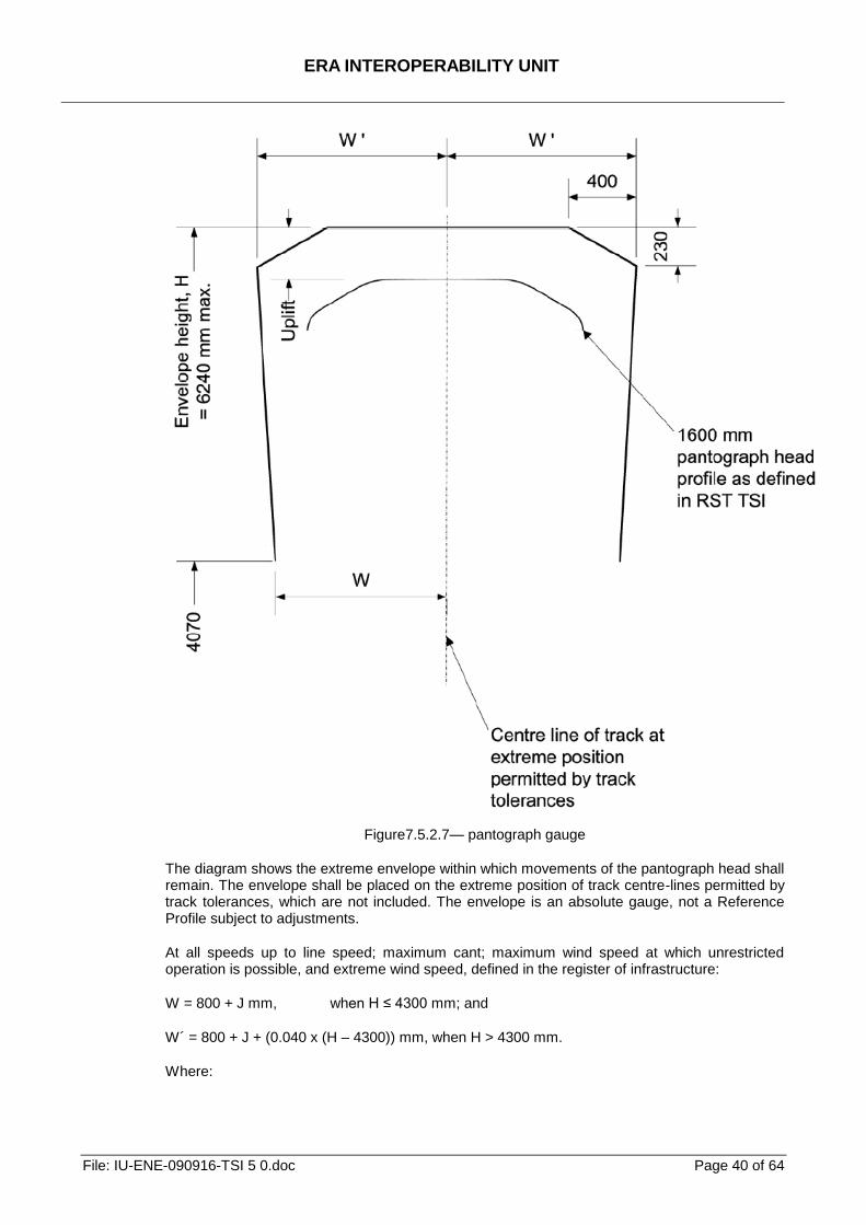
ERA INTEROPERABILITY UNIT
File: IU-ENE-090916-TSI 5 0.doc Page 40 of 64
Figure7.5.2.7— pantograph gauge
The diagram shows the extreme envelope within which movements of the pantograph head shall remain. The envelope shall be placed on the extreme position of track centre-lines permitted by track tolerances, which are not included. The envelope is an absolute gauge, not a Reference Profile subject to adjustments.
At all speeds up to line speed; maximum cant; maximum wind speed at which unrestricted operation is possible, and extreme wind speed, defined in the register of infrastructure:
W = 800 + J mm, when H ≤ 4300 mm; and
W´ = 800 + J + (0.040 x (H – 4300)) mm, when H > 4300 mm.
Where:
ERA INTEROPERABILITY UNIT
File: IU-ENE-090916-TSI 5 0.doc Page 41 of 64
H = Height to top of envelope above rail level (in mm). The dimension is the sum of the contact wire height and the provision for uplift.
J = 200 mm on straight track.
J = 230 mm on curved track.
J = 190 mm (minimum) where constrained by clearance to civil infrastructure that cannot be economically increased.
Additional allowances shall be made including wear of contact wire, mechanical clearance, static or dynamic electrical clearance.
7.5.2.7.4. 600/750 V DC Electrified Railway using ground level conductor rails
P case
Lines equipped with the electrification system operating at 600/750 V DC and utilising ground level top-contact conductor rails in a three and/or four rail configuration shall continue to be upgraded, renewed and extended where this is economically justified. National Standards shall apply.
7.5.2.7.5. Protective provisions of overhead contact line system (4.7.3)
P case
In the reference to EN50122-1:1997 clause 5.1, the special national condition to this clause (5.1.2.1) shall apply.
ERA INTEROPERABILITY UNIT
File: IU-ENE-090916-TSI 5 0.doc Page 42 of 64
8. List of Annexes
A Conformity assessment of Interoperability Constituents
B EC verification of the energy subsystem C Register of infrastructure, information on the energy subsystem D Register of rolling stock, information required by the energy subsystem E Determination of the mechanical kinematic pantograph gauge F Phase and system separation section solutions G Power factor H Electrical protection: main circuit breaker tripping I List of referenced standards Z Glossary
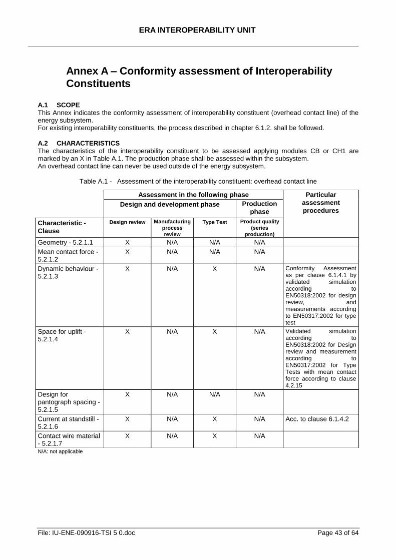
ERA INTEROPERABILITY UNIT
File: IU-ENE-090916-TSI 5 0.doc Page 43 of 64
Annex A – Conformity assessment of Interoperability
Constituents A.1 SCOPE This Annex indicates the conformity assessment of interoperability constituent (overhead contact line) of the energy subsystem. For existing interoperability constituents, the process described in chapter 6.1.2. shall be followed.
A.2 CHARACTERISTICS The characteristics of the interoperability constituent to be assessed applying modules CB or CH1 are marked by an X in Table A.1. The production phase shall be assessed within the subsystem. An overhead contact line can never be used outside of the energy subsystem.
Table A.1 - Assessment of the interoperability constituent: overhead contact line
N/A: not applicable
Assessment in the following phase Particular
assessment
procedures Design and development phase Production
phase
Characteristic -
Clause
Design review
Manufacturing
process
review
Type Test Product quality
(series
production)
Geometry - 5.2.1.1 X N/A N/A N/A
Mean contact force - 5.2.1.2
X N/A N/A N/A
Dynamic behaviour - 5.2.1.3
X N/A X N/A Conformity Assessment as per clause 6.1.4.1 by validated simulation according to EN50318:2002 for design review, and measurements according to EN50317:2002 for type test
Space for uplift - 5.2.1.4
X N/A X N/A Validated simulation according to EN50318:2002 for Design review and measurement according to EN50317:2002 for Type Tests with mean contact force according to clause 4.2.15
Design for pantograph spacing - 5.2.1.5
X N/A N/A N/A
Current at standstill - 5.2.1.6
X N/A X N/A Acc. to clause 6.1.4.2
Contact wire material - 5.2.1.7
X N/A X N/A
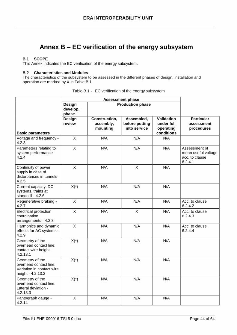
ERA INTEROPERABILITY UNIT
File: IU-ENE-090916-TSI 5 0.doc Page 44 of 64
Annex B – EC verification of the energy subsystem
B.1 SCOPE This Annex indicates the EC verification of the energy subsystem.
B.2 Characteristics and Modules The characteristics of the subsystem to be assessed in the different phases of design, installation and operation are marked by X in Table B.1.
Table B.1 - EC verification of the energy subsystem
Basic parameters
Assessment phase
Design
develop.
phase
Production phase
Design
review
Construction,
assembly,
mounting
Assembled,
before putting
into service
Validation
under full
operating
conditions
Particular
assessment
procedures
Voltage and frequency - 4.2.3
X N/A N/A N/A
Parameters relating to system performance - 4.2.4
X N/A N/A N/A Assessment of mean useful voltage acc. to clause 6.2.4.1
Continuity of power supply in case of disturbances in tunnels- 4.2.5
X N/A X N/A
Current capacity, DC systems, trains at standstill - 4.2.6
X(*) N/A N/A N/A
Regenerative braking - 4.2.7
X N/A N/A N/A Acc. to clause 6.2.4.2
Electrical protection coordination arrangements - 4.2.8
X N/A X N/A Acc. to clause 6.2.4.3
Harmonics and dynamic effects for AC systems- 4.2.9
X N/A N/A N/A Acc. to clause 6.2.4.4
Geometry of the overhead contact line: contact wire height - 4.2.13.1
X(*) N/A N/A N/A
Geometry of the overhead contact line: Variation in contact wire height - 4.2.13.2
X(*) N/A N/A N/A
Geometry of the overhead contact line: Lateral deviation - 4.2.13.3
X(*) N/A N/A N/A
Pantograph gauge - 4.2.14
X
N/A N/A
N/A
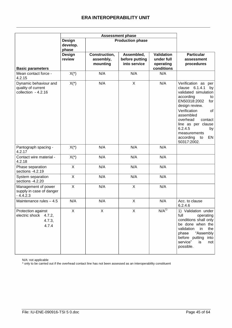
ERA INTEROPERABILITY UNIT
File: IU-ENE-090916-TSI 5 0.doc Page 45 of 64
Basic parameters
Assessment phase
Design
develop.
phase
Production phase
Design
review
Construction,
assembly,
mounting
Assembled,
before putting
into service
Validation
under full
operating
conditions
Particular
assessment
procedures
Mean contact force - 4.2.15
X(*)
N/A N/A
N/A
Dynamic behaviour and quality of current collection - 4.2.16
X(*) N/A X N/A Verification as per clause 6.1.4.1 by validated simulation according to EN50318:2002 for design review.
Verification of assembled overhead contact line as per clause 6.2.4.5 by measurements according to EN 50317:2002.
Pantograph spacing - 4.2.17
X(*) N/A N/A N/A
Contact wire material - 4.2.18
X(*) N/A N/A N/A
Phase separation sections -4.2.19
X N/A N/A N/A
System separation sections -4.2.20
X N/A N/A N/A
Management of power supply in case of danger - 4.4.2.3
X N/A X N/A
Maintenance rules – 4.5 N/A N/A X N/A Acc. to clause 6.2.4.6
Protection against electric shock 4.7.2,
4.7.3,
4.7.4
X X X N/A1)
1) Validation under full operating conditions shall only be done when the validation in the phase ―Assembly before putting into service‖ is not possible.
N/A: not applicable * only to be carried out if the overhead contact line has not been assessed as an interoperability constituent
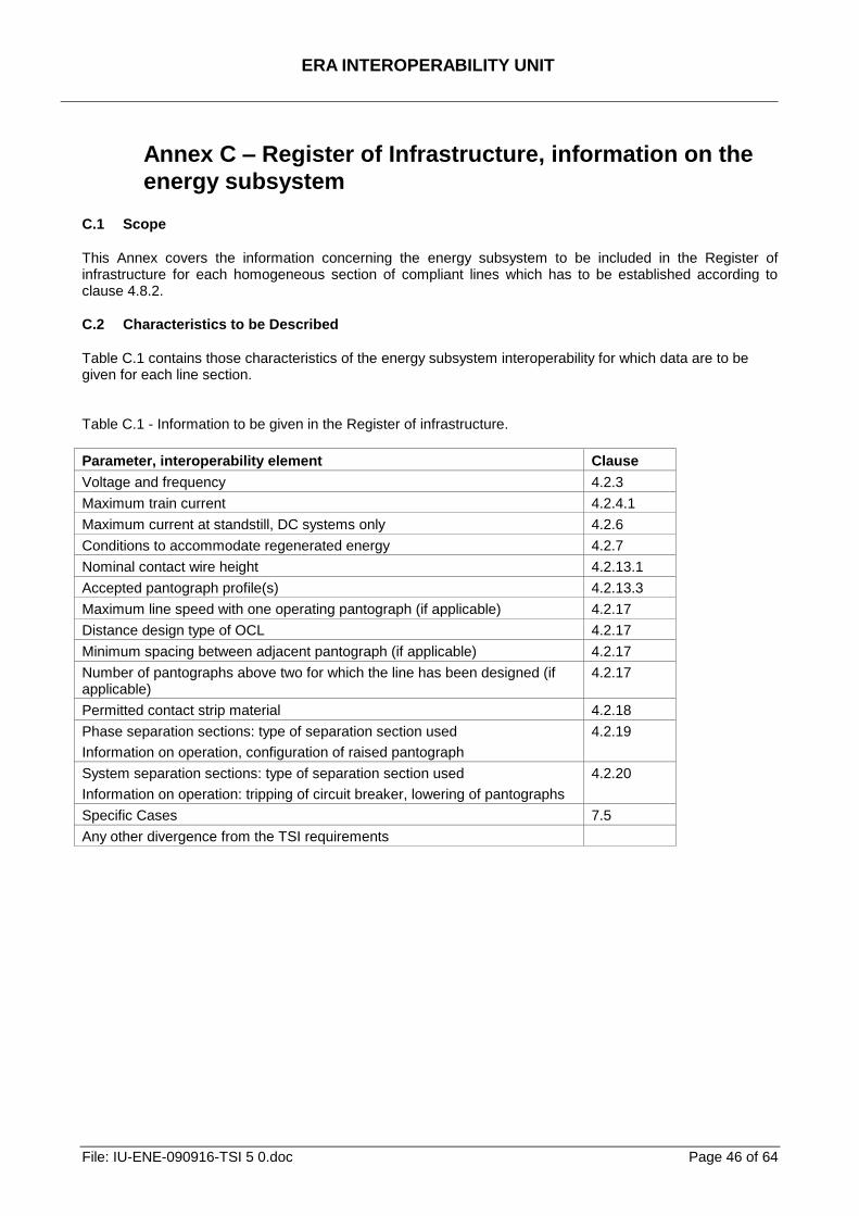
ERA INTEROPERABILITY UNIT
File: IU-ENE-090916-TSI 5 0.doc Page 46 of 64
Annex C – Register of Infrastructure, information on the
energy subsystem
C.1 Scope
This Annex covers the information concerning the energy subsystem to be included in the Register of infrastructure for each homogeneous section of compliant lines which has to be established according to clause 4.8.2.
C.2 Characteristics to be Described
Table C.1 contains those characteristics of the energy subsystem interoperability for which data are to be given for each line section. Table C.1 - Information to be given in the Register of infrastructure.
Parameter, interoperability element Clause
Voltage and frequency 4.2.3
Maximum train current 4.2.4.1
Maximum current at standstill, DC systems only 4.2.6
Conditions to accommodate regenerated energy 4.2.7
Nominal contact wire height 4.2.13.1
Accepted pantograph profile(s) 4.2.13.3
Maximum line speed with one operating pantograph (if applicable) 4.2.17
Distance design type of OCL 4.2.17
Minimum spacing between adjacent pantograph (if applicable) 4.2.17
Number of pantographs above two for which the line has been designed (if applicable)
4.2.17
Permitted contact strip material 4.2.18
Phase separation sections: type of separation section used
Information on operation, configuration of raised pantograph
4.2.19
System separation sections: type of separation section used
Information on operation: tripping of circuit breaker, lowering of pantographs
4.2.20
Specific Cases 7.5
Any other divergence from the TSI requirements
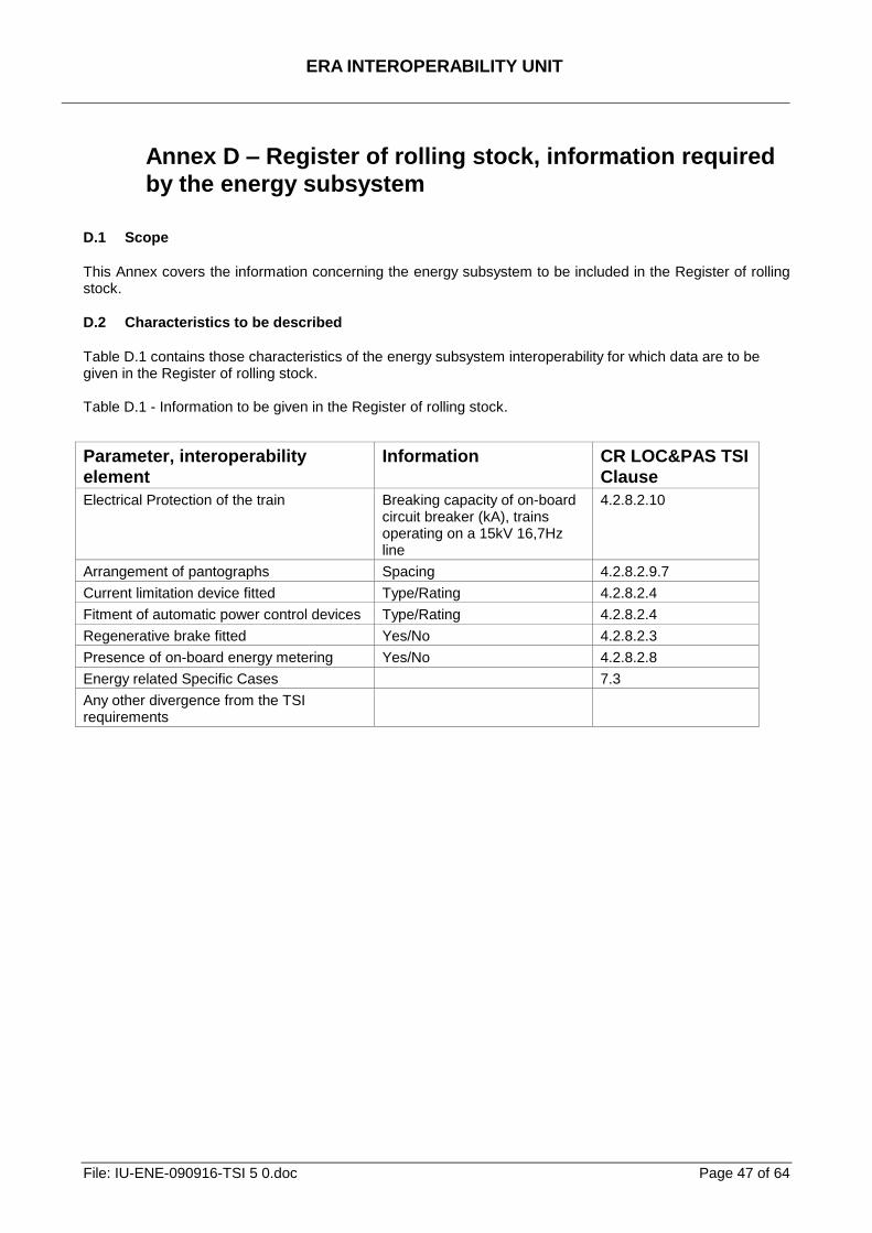
ERA INTEROPERABILITY UNIT
File: IU-ENE-090916-TSI 5 0.doc Page 47 of 64
Annex D – Register of rolling stock, information required
by the energy subsystem
D.1 Scope
This Annex covers the information concerning the energy subsystem to be included in the Register of rolling stock.
D.2 Characteristics to be described
Table D.1 contains those characteristics of the energy subsystem interoperability for which data are to be given in the Register of rolling stock. Table D.1 - Information to be given in the Register of rolling stock.
Parameter, interoperability
element
Information CR LOC&PAS TSI
Clause
Electrical Protection of the train Breaking capacity of on-board circuit breaker (kA), trains operating on a 15kV 16,7Hz line
4.2.8.2.10
Arrangement of pantographs Spacing 4.2.8.2.9.7
Current limitation device fitted Type/Rating 4.2.8.2.4
Fitment of automatic power control devices Type/Rating 4.2.8.2.4
Regenerative brake fitted Yes/No 4.2.8.2.3
Presence of on-board energy metering Yes/No 4.2.8.2.8
Energy related Specific Cases 7.3
Any other divergence from the TSI requirements

ERA INTEROPERABILITY UNIT
File: IU-ENE-090916-TSI 5 0.doc Page 48 of 64
Annex E – Determination of the mechanical kinematic
pantograph gauge
E.1 General
E.1.1 Space to be cleared for electrified lines In the case of lines electrified by an overhead contact line, an additional space should be cleared:
to accommodate the OCL equipment
to allow the free passage of the pantograph.
The electrical gauge should be considered by the Infrastructure Manager and is a subject to national rules. The second item is covered in detail below. E.1.2 Particularities The pantograph gauge differs in some aspects from the obstacle gauge:
The pantograph is (partly) live and, for this reason, an electrical clearance is to be complied with, according to the nature of the obstacle (insulated or not).
The presence of insulating horns should be taken into account, where necessary. Therefore a double reference contour has to be defined to take account of the mechanical and electrical interference simultaneously.
In collecting condition, the pantograph is in permanent contact with the contact wire and, for this reason, its height is variable. So is the height of the pantograph gauge.
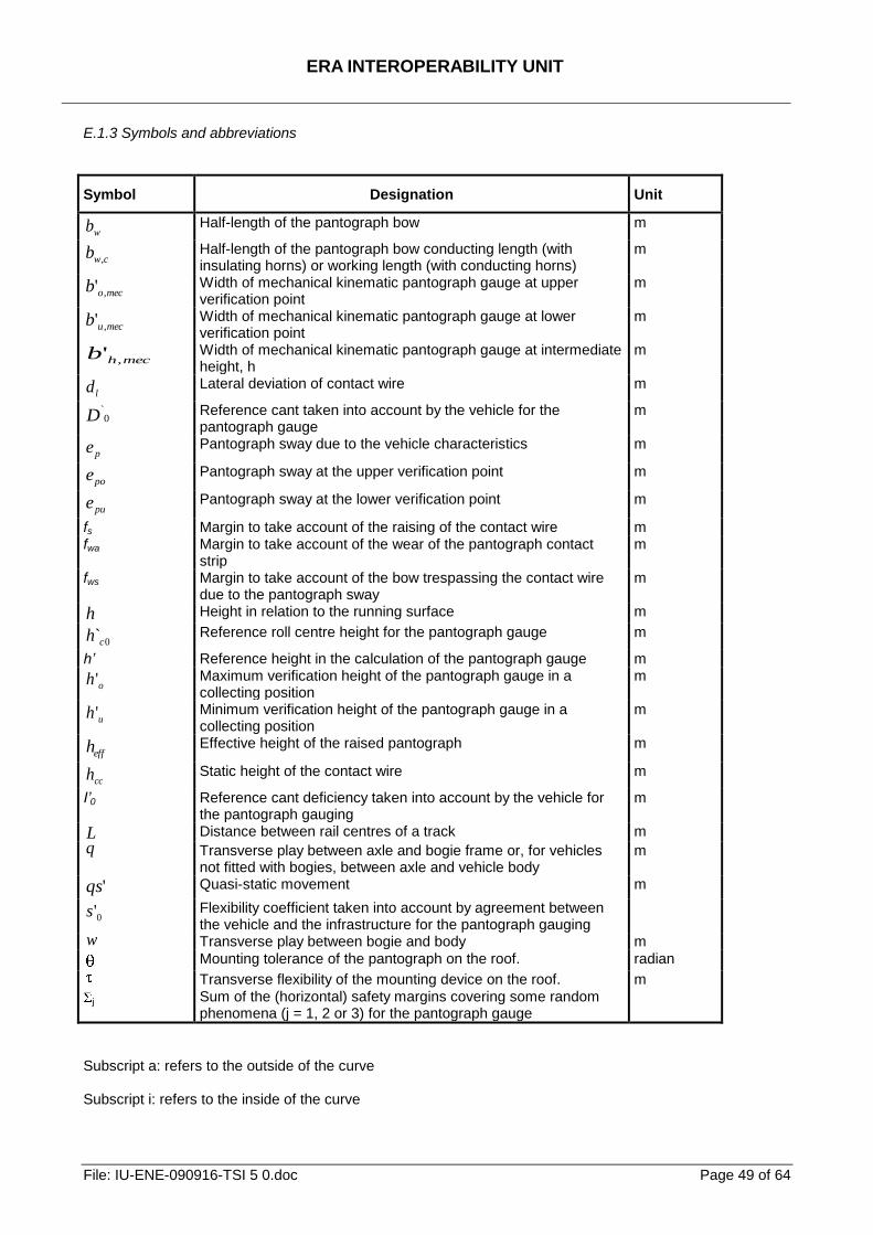
ERA INTEROPERABILITY UNIT
File: IU-ENE-090916-TSI 5 0.doc Page 49 of 64
E.1.3 Symbols and abbreviations
Symbol Designation Unit
wb Half-length of the pantograph bow m
cwb , Half-length of the pantograph bow conducting length (with insulating horns) or working length (with conducting horns)
m
mecob ,' Width of mechanical kinematic pantograph gauge at upper verification point
m
mecub ,' Width of mechanical kinematic pantograph gauge at lower verification point
m
mechb ,' Width of mechanical kinematic pantograph gauge at intermediate height, h
m
ld Lateral deviation of contact wire m
0`D
Reference cant taken into account by the vehicle for the pantograph gauge
m
pe Pantograph sway due to the vehicle characteristics m
poe Pantograph sway at the upper verification point m
pue Pantograph sway at the lower verification point m
fs Margin to take account of the raising of the contact wire m fwa Margin to take account of the wear of the pantograph contact
strip m
fws Margin to take account of the bow trespassing the contact wire due to the pantograph sway
m
h Height in relation to the running surface m
0c̀h Reference roll centre height for the pantograph gauge m
h’ Reference height in the calculation of the pantograph gauge m
oh ' Maximum verification height of the pantograph gauge in a collecting position
m
uh ' Minimum verification height of the pantograph gauge in a collecting position
m
effh Effective height of the raised pantograph m
cch Static height of the contact wire m
I’0 Reference cant deficiency taken into account by the vehicle for the pantograph gauging
m
L Distance between rail centres of a track m
q Transverse play between axle and bogie frame or, for vehicles not fitted with bogies, between axle and vehicle body
m
'qs Quasi-static movement m
0's Flexibility coefficient taken into account by agreement between the vehicle and the infrastructure for the pantograph gauging
w Transverse play between bogie and body m
Mounting tolerance of the pantograph on the roof. radian
Transverse flexibility of the mounting device on the roof. m
j Sum of the (horizontal) safety margins covering some random phenomena (j = 1, 2 or 3) for the pantograph gauge
Subscript a: refers to the outside of the curve Subscript i: refers to the inside of the curve
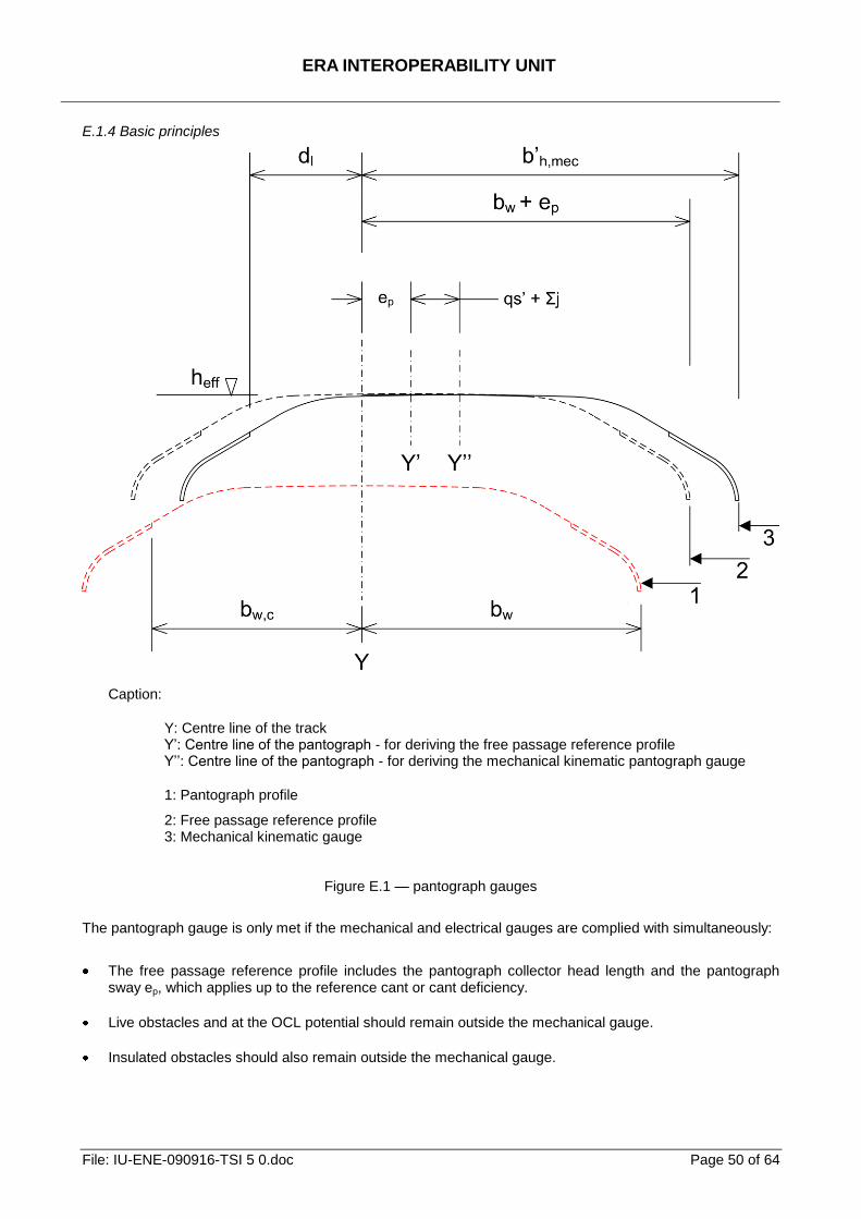
ERA INTEROPERABILITY UNIT
File: IU-ENE-090916-TSI 5 0.doc Page 50 of 64
E.1.4 Basic principles
Caption:
Y: Centre line of the track Y’: Centre line of the pantograph - for deriving the free passage reference profile Y’’: Centre line of the pantograph - for deriving the mechanical kinematic pantograph gauge
1: Pantograph profile
2: Free passage reference profile 3: Mechanical kinematic gauge
Figure E.1 — pantograph gauges
The pantograph gauge is only met if the mechanical and electrical gauges are complied with simultaneously:
The free passage reference profile includes the pantograph collector head length and the pantograph sway ep, which applies up to the reference cant or cant deficiency.
Live obstacles and at the OCL potential should remain outside the mechanical gauge.
Insulated obstacles should also remain outside the mechanical gauge.
ERA INTEROPERABILITY UNIT
File: IU-ENE-090916-TSI 5 0.doc Page 51 of 64
Non insulated obstacles (earthed or at a potential different from the OCL) should remain outside the mechanical and electrical gauges.
Figure E.1 shows the pantograph mechanical gauges.
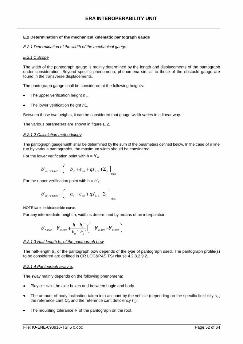
ERA INTEROPERABILITY UNIT
File: IU-ENE-090916-TSI 5 0.doc Page 52 of 64
E.2 Determination of the mechanical kinematic pantograph gauge
E.2.1 Determination of the width of the mechanical gauge
E.2.1.1 Scope
The width of the pantograph gauge is mainly determined by the length and displacements of the pantograph under consideration. Beyond specific phenomena, phenomena similar to those of the obstacle gauge are found in the transverse displacements. The pantograph gauge shall be considered at the following heights:
The upper verification height h’o.
The lower verification height h’u.
Between those two heights, it can be considered that gauge width varies in a linear way. The various parameters are shown in figure E.2.
E.2.1.2 Calculation methodology
The pantograph gauge width shall be determined by the sum of the parameters defined below. In the case of a line run by various pantographs, the maximum width should be considered.
For the lower verification point with h = h`u:
max/),/( '' jaipuwmecaiu qsebb
For the upper verification point with h = h`o:
max/),/( '' jaipowmecaio qsebb
NOTE i/a = inside/outside curve.
For any intermediate height h, width is determined by means of an interpolation:
mecumeco
uo
umecumech bb
hh
hhbb ,,,, ''.
``
`''
E.2.1.3 Half-length bw of the pantograph bow
The half-length bw of the pantograph bow depends of the type of pantograph used. The pantograph profile(s) to be considered are defined in CR LOC&PAS TSI clause 4.2.8.2.9.2.
E.2.1.4 Pantograph sway ep
The sway mainly depends on the following phenomena:
Play q + w in the axle boxes and between bogie and body.
The amount of body inclination taken into account by the vehicle (depending on the specific flexibility s0’, the reference cant D’0 and the reference cant deficiency I’0).
The mounting tolerance of the pantograph on the roof.
ERA INTEROPERABILITY UNIT
File: IU-ENE-090916-TSI 5 0.doc Page 53 of 64
The transverse flexibility of the mounting device on the roof.
The height under consideration h’.
The projections caused by overthrow of the pantograph on curves.
Loading dissymmetry.
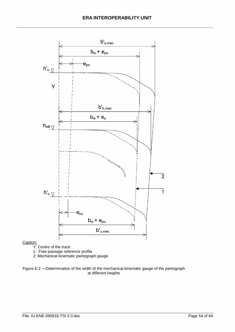
ERA INTEROPERABILITY UNIT
File: IU-ENE-090916-TSI 5 0.doc Page 54 of 64
Caption:
Y: Centre of the track 1: Free passage reference profile 2: Mechanical kinematic pantograph gauge
Figure E.2 —Determination of the width of the mechanical kinematic gauge of the pantograph at different heights
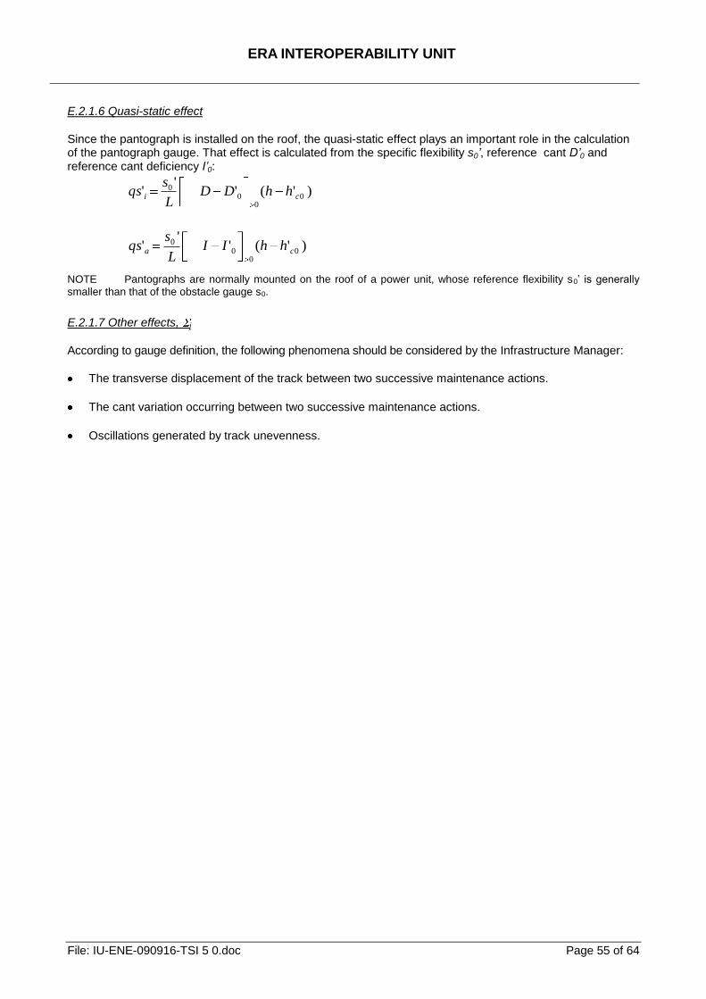
ERA INTEROPERABILITY UNIT
File: IU-ENE-090916-TSI 5 0.doc Page 55 of 64
E.2.1.6 Quasi-static effect
Since the pantograph is installed on the roof, the quasi-static effect plays an important role in the calculation of the pantograph gauge. That effect is calculated from the specific flexibility s0’, reference cant D’0 and reference cant deficiency I’0:
)'(''
' 00
00
ci hhDDL
sqs
)'(''
' 00
00
ca hhIIL
sqs
NOTE Pantographs are normally mounted on the roof of a power unit, whose reference flexibility s0’ is generally
smaller than that of the obstacle gauge s0.
E.2.1.7 Other effects, j
According to gauge definition, the following phenomena should be considered by the Infrastructure Manager:
The transverse displacement of the track between two successive maintenance actions.
The cant variation occurring between two successive maintenance actions.
Oscillations generated by track unevenness.
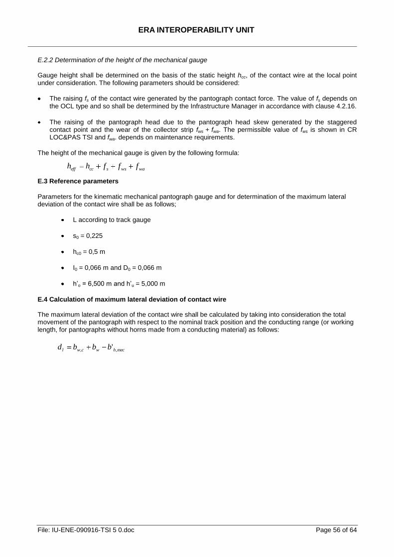
ERA INTEROPERABILITY UNIT
File: IU-ENE-090916-TSI 5 0.doc Page 56 of 64
E.2.2 Determination of the height of the mechanical gauge Gauge height shall be determined on the basis of the static height hcc, of the contact wire at the local point under consideration. The following parameters should be considered:
The raising fs of the contact wire generated by the pantograph contact force. The value of fs depends on the OCL type and so shall be determined by the Infrastructure Manager in accordance with clause 4.2.16.
The raising of the pantograph head due to the pantograph head skew generated by the staggered contact point and the wear of the collector strip fws + fwa. The permissible value of fws is shown in CR LOC&PAS TSI and fwa. depends on maintenance requirements.
The height of the mechanical gauge is given by the following formula:
wawsscceff fffhh
E.3 Reference parameters
Parameters for the kinematic mechanical pantograph gauge and for determination of the maximum lateral deviation of the contact wire shall be as follows;
L according to track gauge
s0 = 0,225
hc0 = 0,5 m
I0 = 0,066 m and D0 = 0,066 m
h’o = 6,500 m and h’u = 5,000 m
E.4 Calculation of maximum lateral deviation of contact wire The maximum lateral deviation of the contact wire shall be calculated by taking into consideration the total movement of the pantograph with respect to the nominal track position and the conducting range (or working length, for pantographs without horns made from a conducting material) as follows:
mechwcwl bbbd ,, '
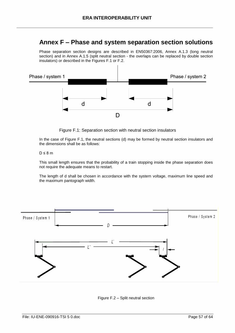
ERA INTEROPERABILITY UNIT
File: IU-ENE-090916-TSI 5 0.doc Page 57 of 64
Annex F – Phase and system separation section solutions
Phase separation section designs are described in EN50367:2006, Annex A.1.3 (long neutral section) and in Annex A.1.5 (split neutral section - the overlaps can be replaced by double section insulators) or described in the Figures F.1 or F.2.
Figure F.1: Separation section with neutral section insulators
In the case of Figure F.1, the neutral sections (d) may be formed by neutral section insulators and the dimensions shall be as follows:
D ≤ 8 m
This small length ensures that the probability of a train stopping inside the phase separation does not require the adequate means to restart.
The length of d shall be chosen in accordance with the system voltage, maximum line speed and the maximum pantograph width.
Figure F.2 – Split neutral section
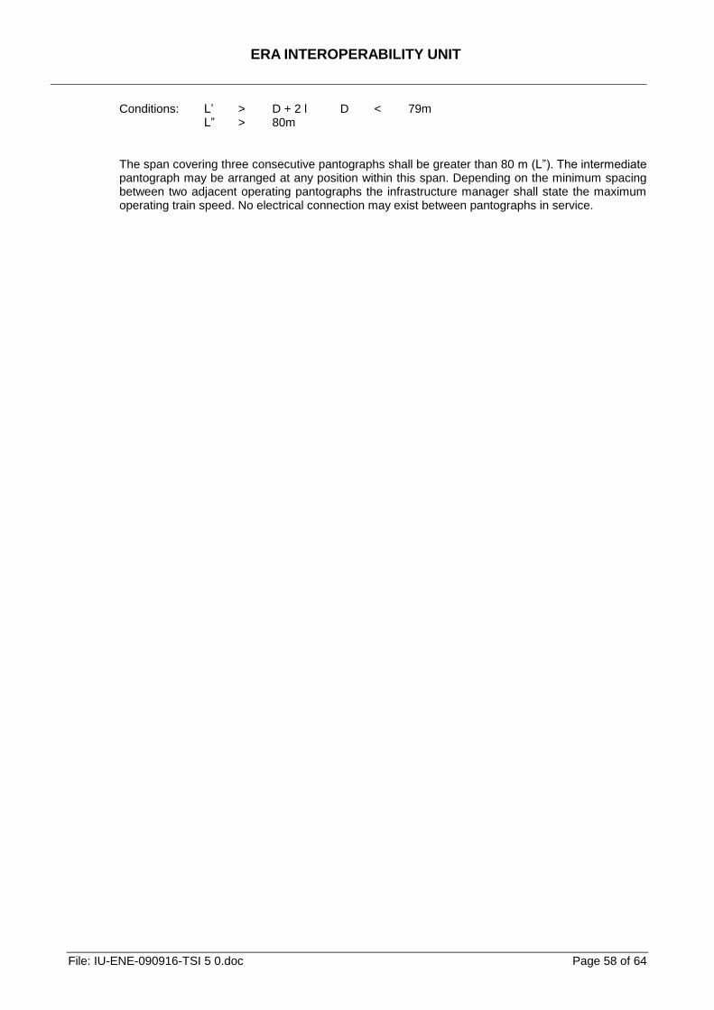
ERA INTEROPERABILITY UNIT
File: IU-ENE-090916-TSI 5 0.doc Page 58 of 64
Conditions: L’ > D + 2 l D < 79m L‖ > 80m
The span covering three consecutive pantographs shall be greater than 80 m (L‖). The intermediate pantograph may be arranged at any position within this span. Depending on the minimum spacing between two adjacent operating pantographs the infrastructure manager shall state the maximum operating train speed. No electrical connection may exist between pantographs in service.
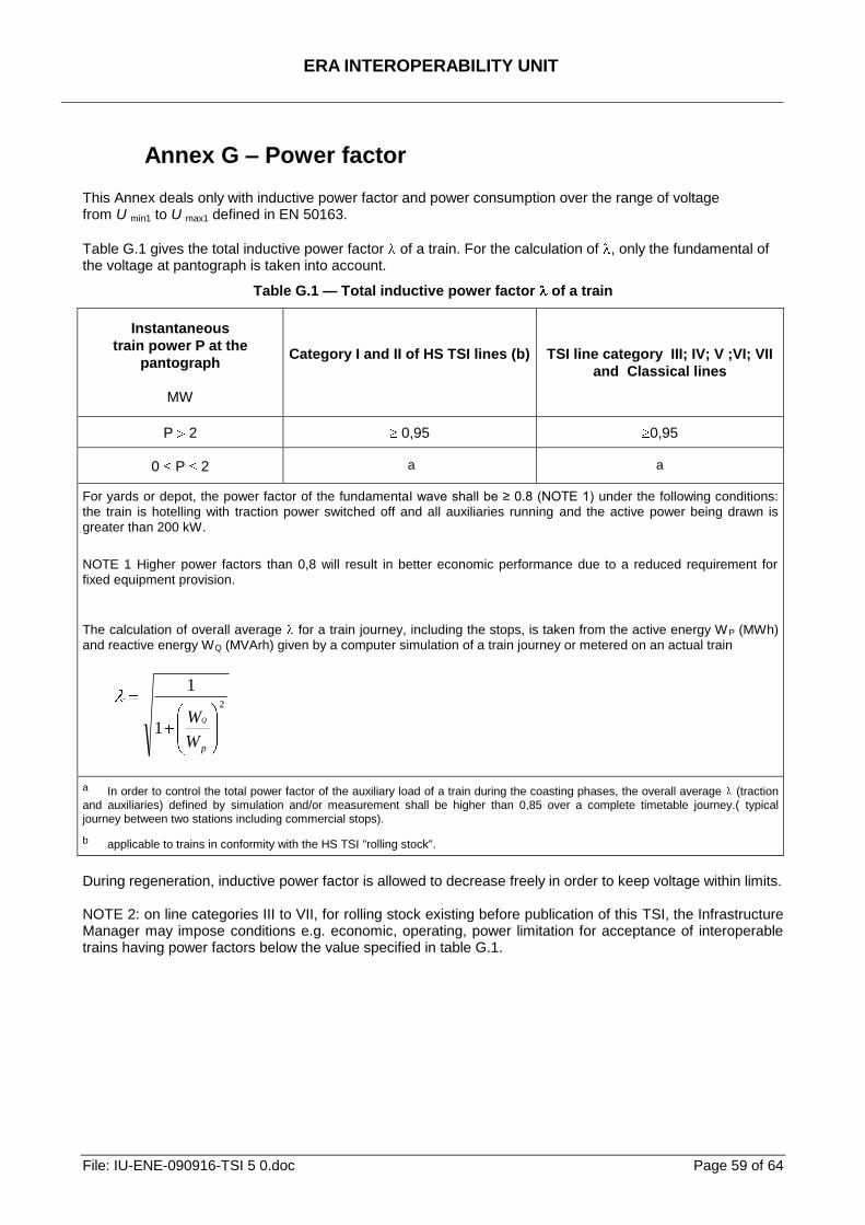
ERA INTEROPERABILITY UNIT
File: IU-ENE-090916-TSI 5 0.doc Page 59 of 64
Annex G – Power factor This Annex deals only with inductive power factor and power consumption over the range of voltage from U min1 to U max1 defined in EN 50163.
Table G.1 gives the total inductive power factor of a train. For the calculation of , only the fundamental of the voltage at pantograph is taken into account.
Table G.1 — Total inductive power factor of a train
Instantaneous
train power P at the
pantograph
MW
Category I and II of HS TSI lines (b)
TSI line category III; IV; V ;VI; VII
and Classical lines
P 2 0,95 0,95
0 P 2 a a
For yards or depot, the power factor of the fundamental wave shall be ≥ 0.8 (NOTE 1) under the following conditions:
the train is hotelling with traction power switched off and all auxiliaries running and the active power being drawn is
greater than 200 kW.
NOTE 1 Higher power factors than 0,8 will result in better economic performance due to a reduced requirement for
fixed equipment provision.
The calculation of overall average for a train journey, including the stops, is taken from the active energy W P (MWh)
and reactive energy WQ (MVArh) given by a computer simulation of a train journey or metered on an actual train
2
1
1
pW
WQ
a In order to control the total power factor of the auxiliary load of a train during the coasting phases, the overall average (traction
and auxiliaries) defined by simulation and/or measurement shall be higher than 0,85 over a complete timetable journey.( typical
journey between two stations including commercial stops).
b applicable to trains in conformity with the HS TSI "rolling stock".
During regeneration, inductive power factor is allowed to decrease freely in order to keep voltage within limits. NOTE 2: on line categories III to VII, for rolling stock existing before publication of this TSI, the Infrastructure Manager may impose conditions e.g. economic, operating, power limitation for acceptance of interoperable trains having power factors below the value specified in table G.1.
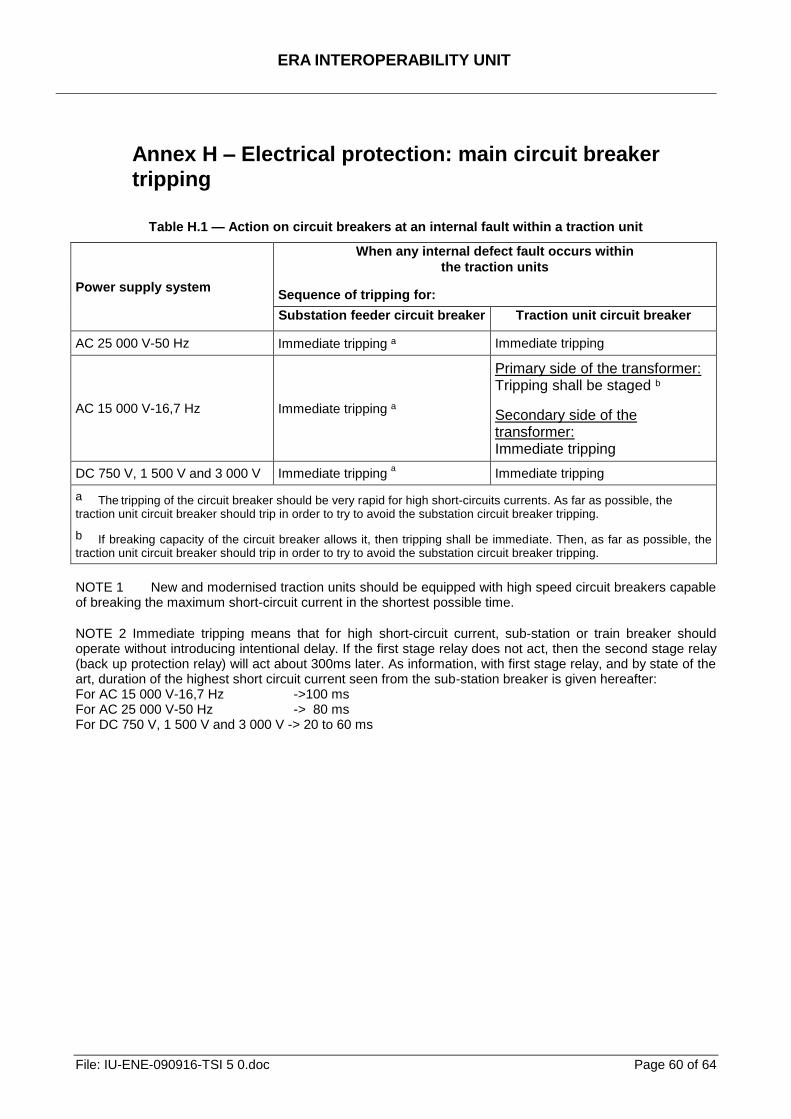
ERA INTEROPERABILITY UNIT
File: IU-ENE-090916-TSI 5 0.doc Page 60 of 64
Annex H – Electrical protection: main circuit breaker
tripping
Table H.1 — Action on circuit breakers at an internal fault within a traction unit
Power supply system
When any internal defect fault occurs within
the traction units
Sequence of tripping for:
Substation feeder circuit breaker Traction unit circuit breaker
AC 25 000 V-50 Hz Immediate tripping a Immediate tripping
AC 15 000 V-16,7 Hz Immediate tripping a
Primary side of the transformer: Tripping shall be staged b
Secondary side of the transformer: Immediate tripping
DC 750 V, 1 500 V and 3 000 V Immediate tripping a Immediate tripping
a The tripping of the circuit breaker should be very rapid for high short-circuits currents. As far as possible, the
traction unit circuit breaker should trip in order to try to avoid the substation circuit breaker tripping.
b If breaking capacity of the circuit breaker allows it, then tripping shall be immediate. Then, as far as possible, the traction unit circuit breaker should trip in order to try to avoid the substation circuit breaker tripping.
NOTE 1 New and modernised traction units should be equipped with high speed circuit breakers capable of breaking the maximum short-circuit current in the shortest possible time.
NOTE 2 Immediate tripping means that for high short-circuit current, sub-station or train breaker should operate without introducing intentional delay. If the first stage relay does not act, then the second stage relay (back up protection relay) will act about 300ms later. As information, with first stage relay, and by state of the art, duration of the highest short circuit current seen from the sub-station breaker is given hereafter: For AC 15 000 V-16,7 Hz ->100 ms For AC 25 000 V-50 Hz -> 80 ms For DC 750 V, 1 500 V and 3 000 V -> 20 to 60 ms
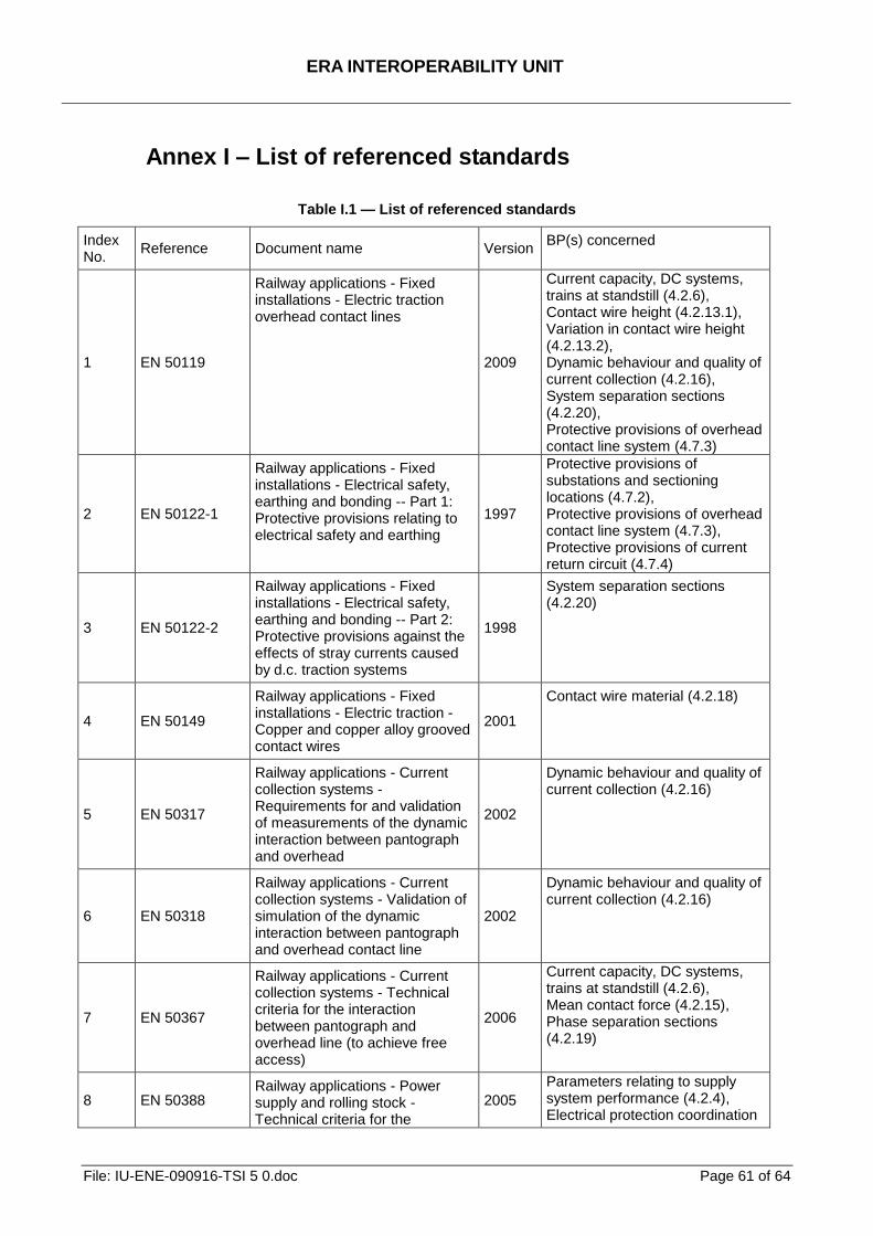
ERA INTEROPERABILITY UNIT
File: IU-ENE-090916-TSI 5 0.doc Page 61 of 64
Annex I – List of referenced standards
Table I.1 — List of referenced standards
Index No.
Reference Document name Version BP(s) concerned
1 EN 50119
Railway applications - Fixed installations - Electric traction overhead contact lines
2009
Current capacity, DC systems, trains at standstill (4.2.6), Contact wire height (4.2.13.1), Variation in contact wire height (4.2.13.2), Dynamic behaviour and quality of current collection (4.2.16), System separation sections (4.2.20), Protective provisions of overhead contact line system (4.7.3)
2 EN 50122-1
Railway applications - Fixed installations - Electrical safety, earthing and bonding -- Part 1: Protective provisions relating to electrical safety and earthing
1997
Protective provisions of substations and sectioning locations (4.7.2), Protective provisions of overhead contact line system (4.7.3), Protective provisions of current return circuit (4.7.4)
3 EN 50122-2
Railway applications - Fixed installations - Electrical safety, earthing and bonding -- Part 2: Protective provisions against the effects of stray currents caused by d.c. traction systems
1998
System separation sections (4.2.20)
4 EN 50149
Railway applications - Fixed installations - Electric traction - Copper and copper alloy grooved contact wires
2001
Contact wire material (4.2.18)
5 EN 50317
Railway applications - Current collection systems - Requirements for and validation of measurements of the dynamic interaction between pantograph and overhead
2002
Dynamic behaviour and quality of current collection (4.2.16)
6 EN 50318
Railway applications - Current collection systems - Validation of simulation of the dynamic interaction between pantograph and overhead contact line
2002
Dynamic behaviour and quality of current collection (4.2.16)
7 EN 50367
Railway applications - Current collection systems - Technical criteria for the interaction between pantograph and overhead line (to achieve free access)
2006
Current capacity, DC systems, trains at standstill (4.2.6), Mean contact force (4.2.15), Phase separation sections (4.2.19)
8 EN 50388 Railway applications - Power supply and rolling stock - Technical criteria for the
2005
Parameters relating to supply system performance (4.2.4), Electrical protection coordination
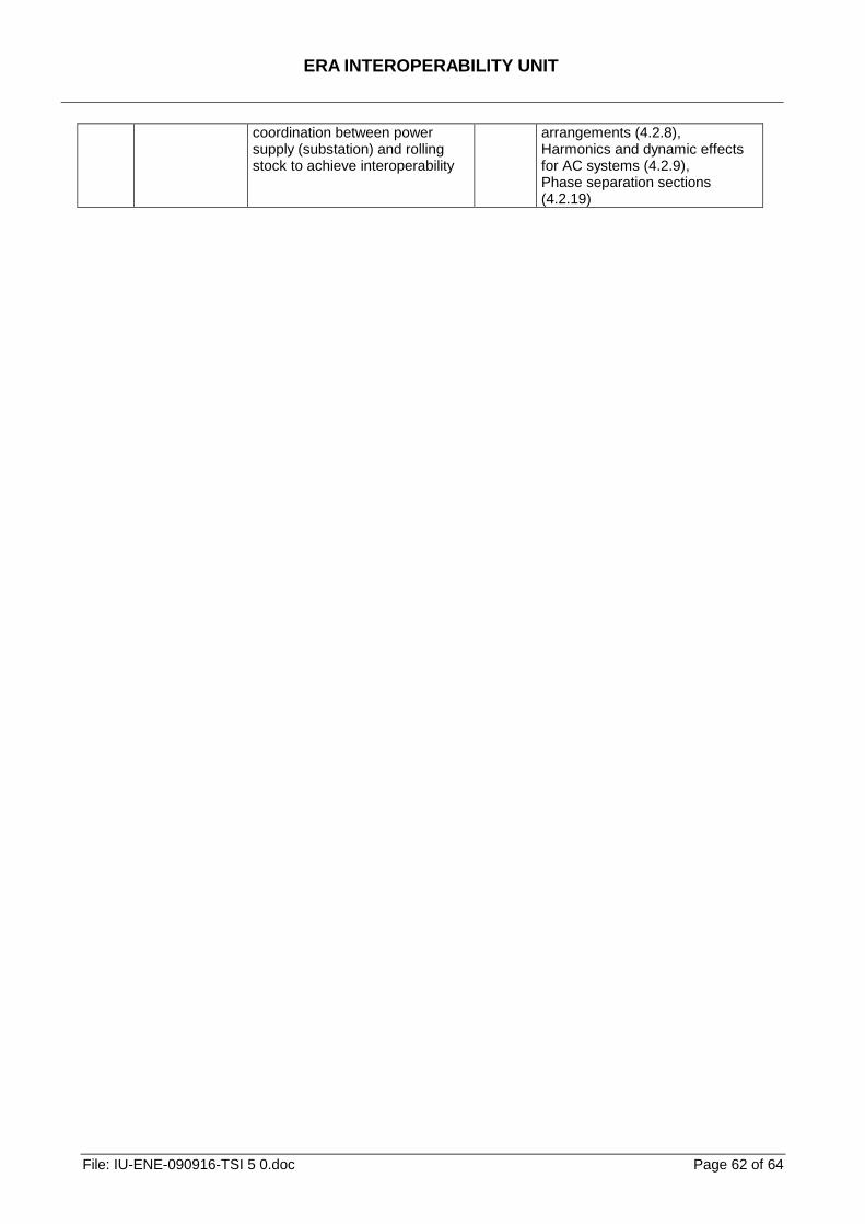
ERA INTEROPERABILITY UNIT
File: IU-ENE-090916-TSI 5 0.doc Page 62 of 64
coordination between power supply (substation) and rolling stock to achieve interoperability
arrangements (4.2.8), Harmonics and dynamic effects for AC systems (4.2.9), Phase separation sections (4.2.19)
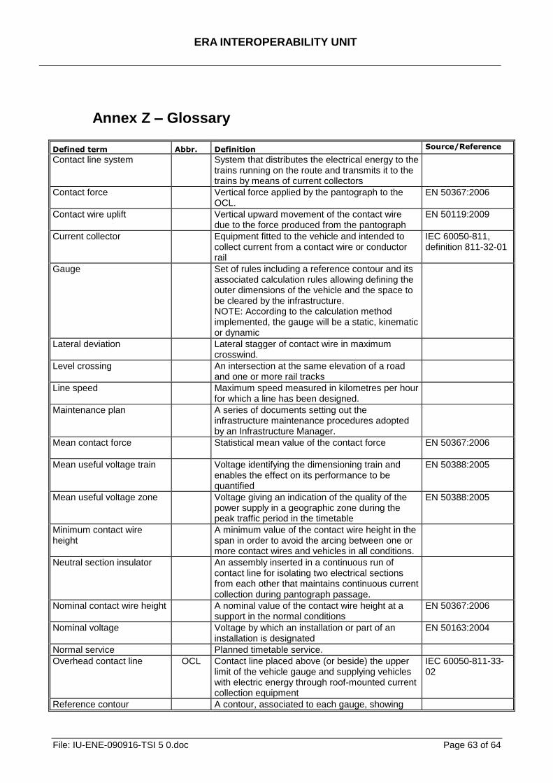
ERA INTEROPERABILITY UNIT
File: IU-ENE-090916-TSI 5 0.doc Page 63 of 64
Annex Z – Glossary
Defined term Abbr. Definition Source/Reference
Contact line system System that distributes the electrical energy to the trains running on the route and transmits it to the trains by means of current collectors
Contact force Vertical force applied by the pantograph to the OCL.
EN 50367:2006
Contact wire uplift Vertical upward movement of the contact wire due to the force produced from the pantograph
EN 50119:2009
Current collector
Equipment fitted to the vehicle and intended to collect current from a contact wire or conductor rail
IEC 60050-811, definition 811-32-01
Gauge Set of rules including a reference contour and its associated calculation rules allowing defining the outer dimensions of the vehicle and the space to be cleared by the infrastructure. NOTE: According to the calculation method implemented, the gauge will be a static, kinematic or dynamic
Lateral deviation Lateral stagger of contact wire in maximum crosswind.
Level crossing
An intersection at the same elevation of a road and one or more rail tracks
Line speed Maximum speed measured in kilometres per hour for which a line has been designed.
Maintenance plan A series of documents setting out the infrastructure maintenance procedures adopted by an Infrastructure Manager.
Mean contact force
Statistical mean value of the contact force EN 50367:2006
Mean useful voltage train Voltage identifying the dimensioning train and enables the effect on its performance to be quantified
EN 50388:2005
Mean useful voltage zone Voltage giving an indication of the quality of the power supply in a geographic zone during the peak traffic period in the timetable
EN 50388:2005
Minimum contact wire height
A minimum value of the contact wire height in the span in order to avoid the arcing between one or more contact wires and vehicles in all conditions.
Neutral section insulator An assembly inserted in a continuous run of contact line for isolating two electrical sections from each other that maintains continuous current collection during pantograph passage.
Nominal contact wire height A nominal value of the contact wire height at a support in the normal conditions
EN 50367:2006
Nominal voltage Voltage by which an installation or part of an installation is designated
EN 50163:2004
Normal service Planned timetable service.
Overhead contact line
OCL Contact line placed above (or beside) the upper limit of the vehicle gauge and supplying vehicles with electric energy through roof-mounted current collection equipment
IEC 60050-811-33-02
Reference contour A contour, associated to each gauge, showing
ERA INTEROPERABILITY UNIT
File: IU-ENE-090916-TSI 5 0.doc Page 64 of 64
Defined term Abbr. Definition Source/Reference
the shape of a cross-section and used as a basis to work out the sizing rules of the infrastructure, on the one hand and of the vehicle, on the other hand.
Return circuit All conductors which form the intended path for the traction return current and the current under fault conditions
EN 50122-1:1997
Static contact force Mean vertical force exerted upwards by the pantograph head on the OCL, and caused by the pantograph-raising device, whilst the pantograph is raised and the vehicle is standstill
EN 50367:2006