interoperable positive train control (ptc) william a petit · interoperable positive train control...
TRANSCRIPT
Interoperable Positive Train Control (PTC)
William A Petit www.BillPetit.com
AREMA 2009 Annual Conference Communications and Signals Track
Abstract: This paper discusses architecture, interoperability and status of an Interoperable Communication Based Signaling (ICBS) system as well as results of an FRA sponsored project verifying the interoperability. The ICBS system uses new technologies to evolve proven signaling principles and safety-critical architectures to achieve the safety, cost and performance benefits of Positive Train Control systems. AREMA Committee 37 (Signal and Train Control) has developed a set of Recommended Practices to specify system architecture, communications protocols, message contents and infrastructure databases as a way of achieving interoperability. Operation is based on applying existing signaling principles, as recommended in the current AREMA C&S Manual, and through modification of existing designs of safety-critical (vital) equipment currently used in revenue service. AREMA Committee 39 (Positive Train Control Wayside Installation, Testing and Maintenance) will take over maintenance of these Manual Parts. The Federal Railroad Administration awarded a grant for demonstration of the system. This project covered development of a test environment and obtaining equipment from multiple suppliers demonstrating the overall system architecture as well as verifying that the Communication-Based Signaling Manual Parts from AREMA allow interoperability to be achieved. This paper will provide a brief review of the manual parts covering the architecture, communications, safety and operational benefits. It will also review the project goals and results of the FRA project; and will compare the operating benefits of signaling-based PTC approaches vs. train-order-based PTC approaches. With the Rail Safety Improvement Act of 2008 (RSIA 2008) mandating positive train control for most North American railroads, this has become a major topic of discussion. This paper will briefly review some of the PTC architectures being considered today while focusing on the interoperable Communication-Based Signaling (CBS) efforts being supported by AREMA Committee 37 (Signal and Train Control systems). A new committee has been formed within AREMA (Committee 39) to address installation, testing and maintenance of Positive Train Control Wayside equipment and systems. Committee 39 will assume responsibility for maintaining the CBS Manual Parts. The RSIA 2008 mandates that each Class I railroad carrier and each railroad providing regularly scheduled intercity or commuter rail passenger transportation shall submit a plan for implementing an interoperable positive train control system by December 31, 2015. This implementation plan must be submitted to the FRA by April 16, 2010. The implementation plan has to be accompanied or preceded by a PTC development plan that describes the technology and supports a Type Approval. Prior to be being placed in revenue service, a PTC Safety plan must be provided that provides the basis for system certification by the FRA. As part of the requirements specified in the RSIA 2008, the Federal Railroad Administration (FRA) is currently developing a new subpart I to their existing Part 236 (Rules, Standards and Instructions governing the installation, inspection, maintenance, and repair of Signal and Train Control systems, devices and appliances). This subpart governs the qualification, installation, maintenance and use of required PTC systems as well as prescribing minimum performance-based safety standards for PTC systems. Subpart I has been drafted through the Rail Safety Advisory
© AREMA 2009 ®
Committee (RSAC) consensus process and will be published for comments in the Federal Register. It is currently anticipated that this will become a final rule in the fall of 2009. As part of the qualification of PTC systems, Subpart I defines PTC details for the previously mentioned PTC Implementation Plan (PTCIP), PTC Development Plan (PTCDP) and PTC Safety Plan (PTCSP). The current draft of subpart I recognizes three different types of PTC systems that may be used. The first type is a non-vital overlay. This system is an overlay on the existing method of operation (e.g. train orders, cTc) but is not built in accordance with the safety principles identified in Appendix C of the rule. Non-vital overlays must reliably perform the mandated PTC functions and reduce the risk associated with accidents preventable by those functions by at least 80%. The next two types of PTC systems require compliance with Appendix C and it is worth a brief discussion of what that means. I interpret Appendix C as requiring systems to be designed and built to the traditional definition of vital or fail-safe as currently used in the signaling community. Essentially, it requires the system to achieve a known safe state in the event of any credible hardware failure (including secondary failures if the first failure is not self-revealing) or software error (typically design errors). Lists of credible hardware failures are provided in sources such as the AREMA Manual of Recommended Practices Section 17. The major difficulty arises when considering the hardware failures of integrated circuits, such as microprocessors, whose credible failures can make the software perform in a completely unforeseeable manner. Most existing vital designs address this through use of an external independent arbiter that removes power from the device allowing less restrictive actions to take place. This independent arbiter is generally built of hardware whose credible failure modes are predictable so that the system can be analyzed for proper and correct operation in the presence of those failure modes. Based upon a cursory understanding of Appendix C, we can now move onto the other 2 types of currently accepted PTC systems. This first is a vital overlay system and consists of a system overlaid on the existing method of operation and is built in accordance with the principles of Appendix C. Vital Overlay systems may be analyzed under an abbreviated risk assessment process (e.g. built in accordance with AREMA Section 17 recommended practices) if their use does not introduce any new risks into the overall system, and does not increase the probability or severity of any of the existing risks. The final type of currently accepted PTC systems is a vital stand-alone system. This type of system may be used for new locations, as a replacement for an existing signal or train control system, or to enhance the capabilities of the current method of operation. In addition to being developed according to the principles of Appendix C, a full risk assessment is required identifying all system hazards and how they are mitigated. The full risk assessment is required as this is the only one of the 3 types of PTC systems that does not depend (at least partially) on the underlying method of operation to meet safety goals.
© AREMA 2009 ®
Having defined the 3 types of PTC systems identified in subpart I, we will now look at some of the PTC systems being developed that should meet the requirements of subpart I. Although there may be other systems available, I will limit this paper to four of those systems with most of the attention paid to the Communication-Based Signaling System (CBS) whose architecture and interoperability are defined in Section 23 of the AREMA Manual of Recommended Practices for Communications and Signals. At the conclusion, I will discuss how these systems may fit into the categories defined in subpart I as well as some thoughts on how they can eventually merge into a single interoperable system. The four systems to be discussed include
• Communications – Based Signaling (CBS) as defined by AREMA C&S Manual • Interoperable Train Control (ITC) to be defined by a consortium of Class I
Railroads • Incremental Train Control System (ITCS), currently in service on Michigan HSR
line and in China • Advanced Civil Speed Enforcement System (ACSES), as used on Northeast
corridor in conjunction with conventional cab signal system. Communication Based Signal System
This project demonstrated that the major suppliers of signaling equipment for the North American railroads could modify their existing safety-critical equipment to support operation of a vital interoperable positive train control system based on signaling principles developed over many decades. The project is referred to either as Communication-Based Signaling (CBS) in the American Railway Engineering and Maintenance of Way Association (AREMA) Manual of Recommended Practices; or Interoperable Communication-Based Signaling (ICBS) in this project. The terms may be used interchangeably.
Project participants included the major suppliers of signal and train control equipment within North America. These suppliers have provided a wide variety of signaling equipment, including processor-based equipment, which has been in revenue service on railroads and transit properties for decades. This includes equipment designed and built to the vital (or fail-safe) requirements of rail and transit properties. The project was sponsored by the Federal Railroad Administration Office of Railroad Development and coordinated through the Railroad Research Foundation (www.railroadresearch.org). Project management was provided by Bill Petit (www.billpetit.com) and the test environment and simulators were provided by Critical Link (www.criticallink.com). The participating suppliers include Alstom Signaling (www.transport.alstom.com), Ansaldo – STS (previously known as Union Switch and Signal) (www.ansaldo-sts.com), General Electric Transportation Systems (www.getransportation.com) and Safetran Systems (www.safetran.com). Financial support was provided by the FRA for the project management and test environment. Three of the suppliers (Ansaldo – STS, GETS and Safetran) received funding covering approximately one third (1/3) of their actual costs. Alstom entered the project later than the others and received no financial support through FRA.
© AREMA 2009 ®
This project was undertaken to verify that a set of interoperability standards developed and maintained through an industry professional organization (American Railway Engineering and Maintenance of Way Association, AREMA, www.arema.org) could be implemented. There are many additional aspects to implementing a complete positive train control system and this project should be seen as part of a pathway toward full interoperable train control
As part of the project, a test environment modeling four railroad sections, each representing a different railroad, was created, along with a communications infrastructure for transporting messages. A conventional cTc computer-aided dispatch system was used to control movement through all of the sections. Each of the suppliers modified their own existing equipment to support the AREMA Recommended Practices and inserted their equipment into the proper location within the overall test environment. Onboard equipment from suppliers was used to move trains seamlessly across all the territories. Experience gained through the project was tabulated and referred to AREMA for inclusion in the next release of Recommended Practices.
All four of the suppliers demonstrated that their modified wayside equipment operated within the system and was interoperable with other equipment. Two of the suppliers demonstrated that their carborne equipment operated within the system (including across all four suppliers waysides) and was interoperable within the overall system.
It is useful to understand the system architecture and philosophy used in developing the CBS system. In principle, a CBS system operates the same as a conventional cab signal system with onboard enforcement except for the following:
1. Physical blocks (as determined by track circuits in conventional systems) are replaced with virtual blocks that are generally equivalent in length to track circuits in cTc territory.
2. Communications via the rails is replaced with a digital data link 3. Train location is determined as an on-board function. 4. An onboard database allows civil speeds to be accurately enforced throughout the
territory as well as allowing braking profiles to take grades and curves into account.
In a CBS system, instead of transmitting vital cab signal information through the rails, an RF communications data link is employed for this function.
The following diagram shows the basics of a Communication Based Signaling System. The communications cloud represents whatever RF communication system is chosen to route the pre-defined messages between the various subsystems.
© AREMA 2009 ®
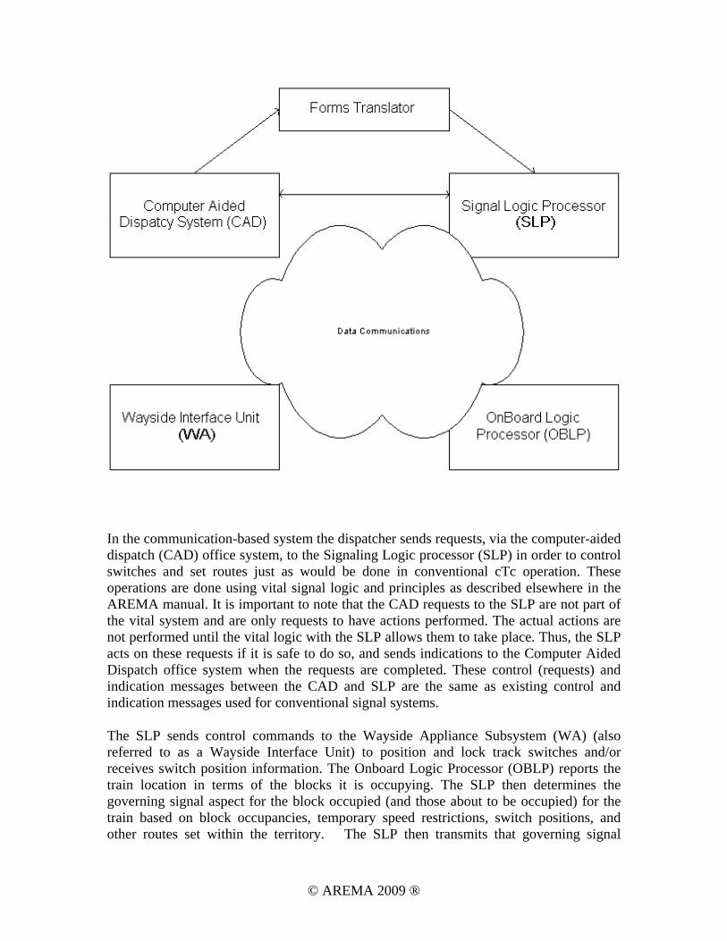
In the communication-based system the dispatcher sends requests, via the computer-aided dispatch (CAD) office system, to the Signaling Logic processor (SLP) in order to control switches and set routes just as would be done in conventional cTc operation. These operations are done using vital signal logic and principles as described elsewhere in the AREMA manual. It is important to note that the CAD requests to the SLP are not part of the vital system and are only requests to have actions performed. The actual actions are not performed until the vital logic with the SLP allows them to take place. Thus, the SLP acts on these requests if it is safe to do so, and sends indications to the Computer Aided Dispatch office system when the requests are completed. These control (requests) and indication messages between the CAD and SLP are the same as existing control and indication messages used for conventional signal systems.
The SLP sends control commands to the Wayside Appliance Subsystem (WA) (also referred to as a Wayside Interface Unit) to position and lock track switches and/or receives switch position information. The Onboard Logic Processor (OBLP) reports the train location in terms of the blocks it is occupying. The SLP then determines the governing signal aspect for the block occupied (and those about to be occupied) for the train based on block occupancies, temporary speed restrictions, switch positions, and other routes set within the territory. The SLP then transmits that governing signal
© AREMA 2009 ®
information to the OBLP. The OBLP determines the governing aspect for the block based on the data received via the data communications link, and the civil speed data contained in the onboard database, and displays the appropriate signal aspect and/or speed limit to the operator, who in turn controls the train appropriately. If the operator does not control the train appropriately, the OBLP determines overspeed and/or about to exceed authority, and requests brakes when required. When actual wayside signals are present the SLP will provide the OBLP with the address of the signal in place of the signal aspect. The OBLP will then request the signal status directly from the signal and use the received signal to determine the limiting aspect/speed for the upcoming block.
Since the number of possible signal aspects is not limited by the physical characteristics of the track as in conventional systems, it is possible to define a larger number of available aspects so that additional information can be conveyed to the engineman. This allows more flexibility in operation and better system throughput.
The communication-based system can also allow the office dispatcher to install temporary speed limits or roadway worker authorities. These are converted through the forms translator to a format usable by the SLP, which then determines the appropriate signal aspects or allowable speeds to be sent to the train.
In late 2007, the Federal Railroad Administration (FRA) (www.fra.dot.gov) provided a grant to demonstrate the operation of an Interoperable Communication-Based Signaling (ICBS) system as defined by AREMA. This includes demonstrating the ability of multiple suppliers to achieve and demonstrate interoperability by following the Recommended Practices.
The FRA grant covered a laboratory demonstration of the system with each of the participating suppliers providing interoperable equipment based on the AREMA Manual Parts. The four major signal suppliers in North America (General Electric Transportation Systems (www.getransportation.com), Safetran Systems Corporation (www.safetran.com), Ansaldo-STS (www.switch.com), and Alstom (www.alstomsignalingsolutions.com) agreed to participate in the project. Critical Link (www.criticallink.com) was chosen to provide the test environment, including simulators, physical interfaces, and integration support.
In order to accomplish the testing, a territory had to be defined that would allow each of the participating suppliers to have a section to control, an interface to adjacent sections, an interface to a control office and onboard systems capable of traversing all 4 sections. In addition, a communications router was developed that was capable of routing information throughout all 4 sections and all the vehicles based on the defined addresses. The approach taken was to develop a set of simulators for each of the subsystems that performed the basic functionality as well as supporting the defined interfaces. The simulators and router were based on PC's with the ICBS defined messages encapsulated and sent via an IP network. After the simulators were developed, each of the participating suppliers then used the simulators at their own facilities as a way of testing their systems prior to incorporating them into the final demonstration.
© AREMA 2009 ®
As each of the suppliers completed various subsystems, they were substituted into the demonstration system at the Critical Link facility in Syracuse, NY. Thus, at the completion of the project, there were no simulators running as they had all been replaced by actual suppliers’ equipment.
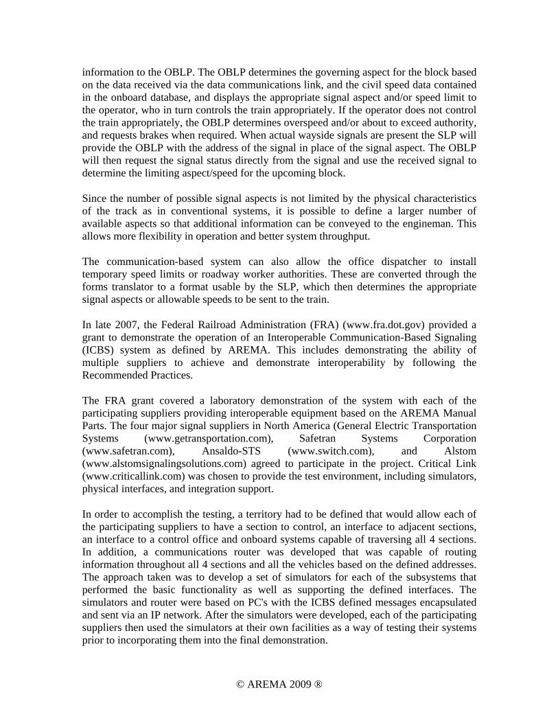
The territory to be simulated consisted of 4 contiguous segments, each with double track. Following is an example of the territory to be controlled by each participant. Splitting the territory into blocks and governing signals was arbitrary. Each application of CBS will allow blocks and signals to be defined as needed to achieve the needed operational performance of that section of railroad. Each of the participating suppliers had a similar territory to control, and the overall territory had 4 of these sections operating contiguously (i.e. a vehicle supplied by a single supplier can move seamlessly across all 4 sections).
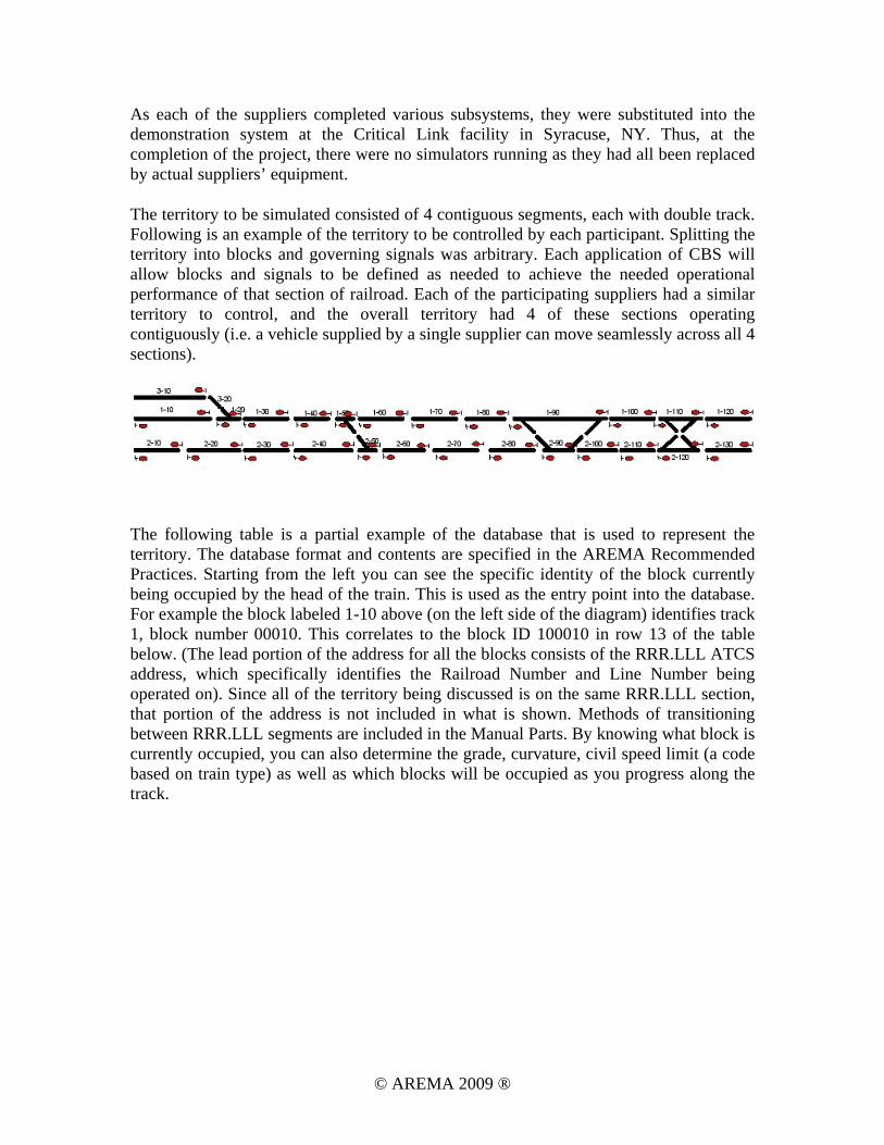
The following table is a partial example of the database that is used to represent the territory. The database format and contents are specified in the AREMA Recommended Practices. Starting from the left you can see the specific identity of the block currently being occupied by the head of the train. This is used as the entry point into the database. For example the block labeled 1-10 above (on the left side of the diagram) identifies track 1, block number 00010. This correlates to the block ID 100010 in row 13 of the table below. (The lead portion of the address for all the blocks consists of the RRR.LLL ATCS address, which specifically identifies the Railroad Number and Line Number being operated on). Since all of the territory being discussed is on the same RRR.LLL section, that portion of the address is not included in what is shown. Methods of transitioning between RRR.LLL segments are included in the Manual Parts. By knowing what block is currently occupied, you can also determine the grade, curvature, civil speed limit (a code based on train type) as well as which blocks will be occupied as you progress along the track.
© AREMA 2009 ®
© AREMA 2009 ®
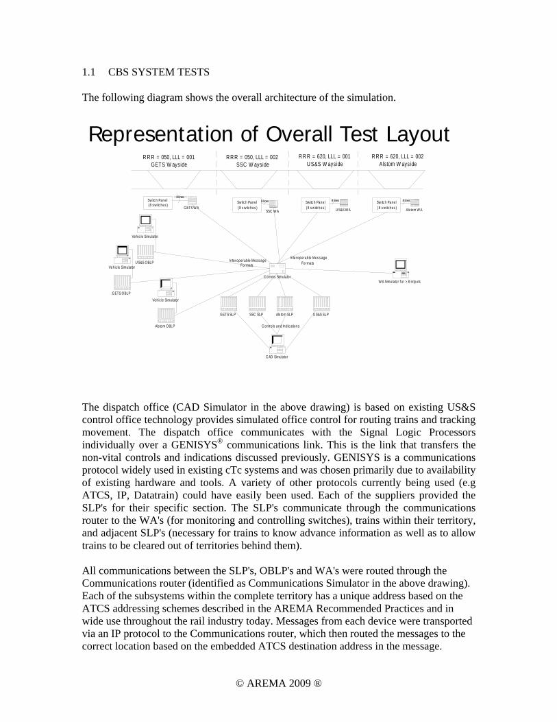
1.1 CBS SYSTEM TESTS
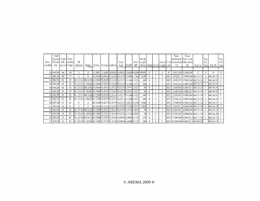
The following diagram shows the overall architecture of the simulation.
R R R = 050, LLL = 001GETS W ayside
R R R = 050, LLL = 002SSC W ayside
R R R = 620, LLL = 001U S&S W ayside
GETS SLP SSC SLP U S&S SLP
C omms Simulator
C AD Simulator
Vehic le Simulator
Vehic le Simulator
Vehic le Simulator
GETS OBLP
Als tom OBLP
U S&S OBLP
GETS W ASSC W A U S&S W A
Sw itc h Panel(8 s w itc hes )
Sw itc h Panel(8 s w itc hes )
Sw itc h Panel(8 s w itc hes )
W A Simulator f or > 8 in lputs
8 lines8 lines8 lines
C ontro ls and Ind ic ations
In teroperable Mes s ageFormats
Interoperab le Mes s ageFormats
Als tom W A
Sw itc h Panel(8 s w itc hes )
8 lines
R R R = 620, LLL = 002Alstom W ayside
Als tom SLP
Representation of Overall Test Layout
The dispatch office (CAD Simulator in the above drawing) is based on existing US&S control office technology provides simulated office control for routing trains and tracking movement. The dispatch office communicates with the Signal Logic Processors individually over a GENISYS® communications link. This is the link that transfers the non-vital controls and indications discussed previously. GENISYS is a communications protocol widely used in existing cTc systems and was chosen primarily due to availability of existing hardware and tools. A variety of other protocols currently being used (e.g ATCS, IP, Datatrain) could have easily been used. Each of the suppliers provided the SLP's for their specific section. The SLP's communicate through the communications router to the WA's (for monitoring and controlling switches), trains within their territory, and adjacent SLP's (necessary for trains to know advance information as well as to allow trains to be cleared out of territories behind them). All communications between the SLP's, OBLP's and WA's were routed through the Communications router (identified as Communications Simulator in the above drawing). Each of the subsystems within the complete territory has a unique address based on the ATCS addressing schemes described in the AREMA Recommended Practices and in wide use throughout the rail industry today. Messages from each device were transported via an IP protocol to the Communications router, which then routed the messages to the correct location based on the embedded ATCS destination address in the message.
© AREMA 2009 ®
When fully integrated, the demonstration showed the ability of trains controlled by different suppliers OBLP’s (each simulating a different railroad) to seamlessly move through the 4 territory sections, each of which is controlled by equipment from a different supplier. The following figures show the equipment supplied by each of the suppliers.
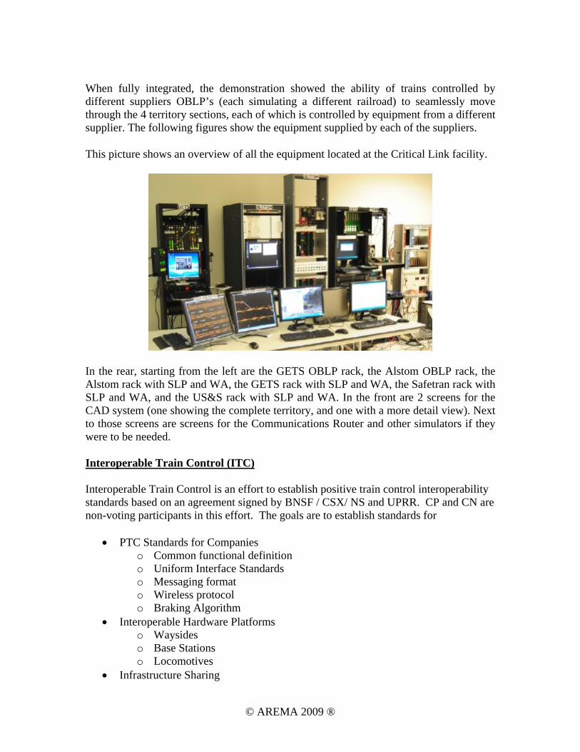
This picture shows an overview of all the equipment located at the Critical Link facility.
In the rear, starting from the left are the GETS OBLP rack, the Alstom OBLP rack, the Alstom rack with SLP and WA, the GETS rack with SLP and WA, the Safetran rack with SLP and WA, and the US&S rack with SLP and WA. In the front are 2 screens for the CAD system (one showing the complete territory, and one with a more detail view). Next to those screens are screens for the Communications Router and other simulators if they were to be needed. Interoperable Train Control (ITC) Interoperable Train Control is an effort to establish positive train control interoperability standards based on an agreement signed by BNSF / CSX/ NS and UPRR. CP and CN are non-voting participants in this effort. The goals are to establish standards for
• PTC Standards for Companies o Common functional definition o Uniform Interface Standards o Messaging format o Wireless protocol o Braking Algorithm
• Interoperable Hardware Platforms o Waysides o Base Stations o Locomotives
• Infrastructure Sharing
© AREMA 2009 ®
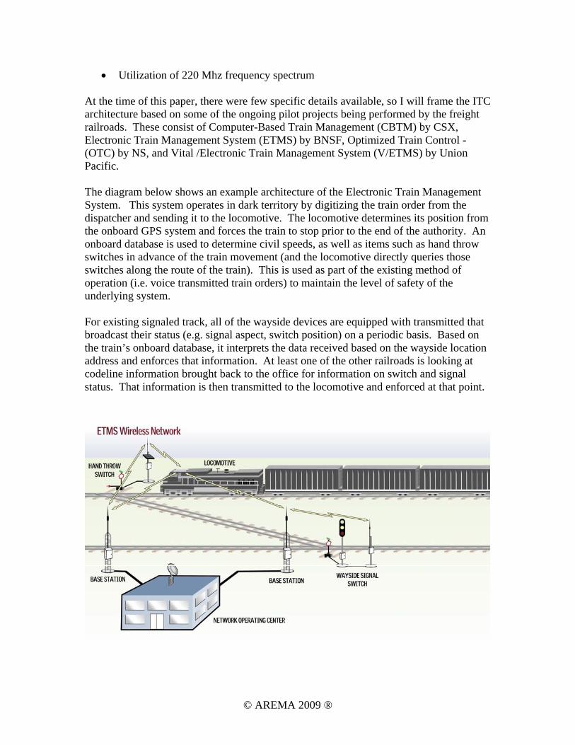
• Utilization of 220 Mhz frequency spectrum At the time of this paper, there were few specific details available, so I will frame the ITC architecture based on some of the ongoing pilot projects being performed by the freight railroads. These consist of Computer-Based Train Management (CBTM) by CSX, Electronic Train Management System (ETMS) by BNSF, Optimized Train Control - (OTC) by NS, and Vital /Electronic Train Management System (V/ETMS) by Union Pacific. The diagram below shows an example architecture of the Electronic Train Management System. This system operates in dark territory by digitizing the train order from the dispatcher and sending it to the locomotive. The locomotive determines its position from the onboard GPS system and forces the train to stop prior to the end of the authority. An onboard database is used to determine civil speeds, as well as items such as hand throw switches in advance of the train movement (and the locomotive directly queries those switches along the route of the train). This is used as part of the existing method of operation (i.e. voice transmitted train orders) to maintain the level of safety of the underlying system. For existing signaled track, all of the wayside devices are equipped with transmitted that broadcast their status (e.g. signal aspect, switch position) on a periodic basis. Based on the train’s onboard database, it interprets the data received based on the wayside location address and enforces that information. At least one of the other railroads is looking at codeline information brought back to the office for information on switch and signal status. That information is then transmitted to the locomotive and enforced at that point.
© AREMA 2009 ®
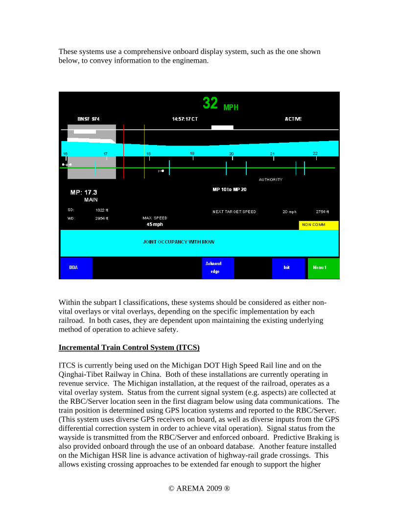
These systems use a comprehensive onboard display system, such as the one shown below, to convey information to the engineman.
Within the subpart I classifications, these systems should be considered as either non-vital overlays or vital overlays, depending on the specific implementation by each railroad. In both cases, they are dependent upon maintaining the existing underlying method of operation to achieve safety. Incremental Train Control System (ITCS) ITCS is currently being used on the Michigan DOT High Speed Rail line and on the Qinghai-Tibet Railway in China. Both of these installations are currently operating in revenue service. The Michigan installation, at the request of the railroad, operates as a vital overlay system. Status from the current signal system (e.g. aspects) are collected at the RBC/Server location seen in the first diagram below using data communications. The train position is determined using GPS location systems and reported to the RBC/Server. (This system uses diverse GPS receivers on board, as well as diverse inputs from the GPS differential correction system in order to achieve vital operation). Signal status from the wayside is transmitted from the RBC/Server and enforced onboard. Predictive Braking is also provided onboard through the use of an onboard database. Another feature installed on the Michigan HSR line is advance activation of highway-rail grade crossings. This allows existing crossing approaches to be extended far enough to support the higher
© AREMA 2009 ®
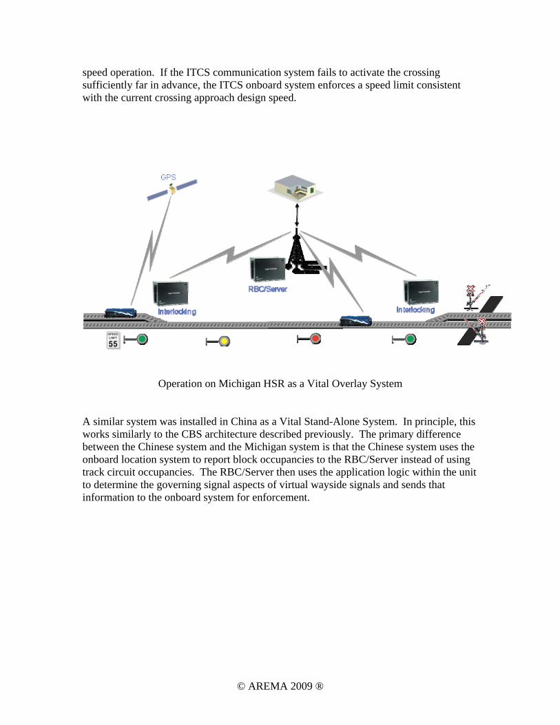
speed operation. If the ITCS communication system fails to activate the crossing sufficiently far in advance, the ITCS onboard system enforces a speed limit consistent with the current crossing approach design speed.
Operation on Michigan HSR as a Vital Overlay System
A similar system was installed in China as a Vital Stand-Alone System. In principle, this works similarly to the CBS architecture described previously. The primary difference between the Chinese system and the Michigan system is that the Chinese system uses the onboard location system to report block occupancies to the RBC/Server instead of using track circuit occupancies. The RBC/Server then uses the application logic within the unit to determine the governing signal aspects of virtual wayside signals and sends that information to the onboard system for enforcement.
© AREMA 2009 ®
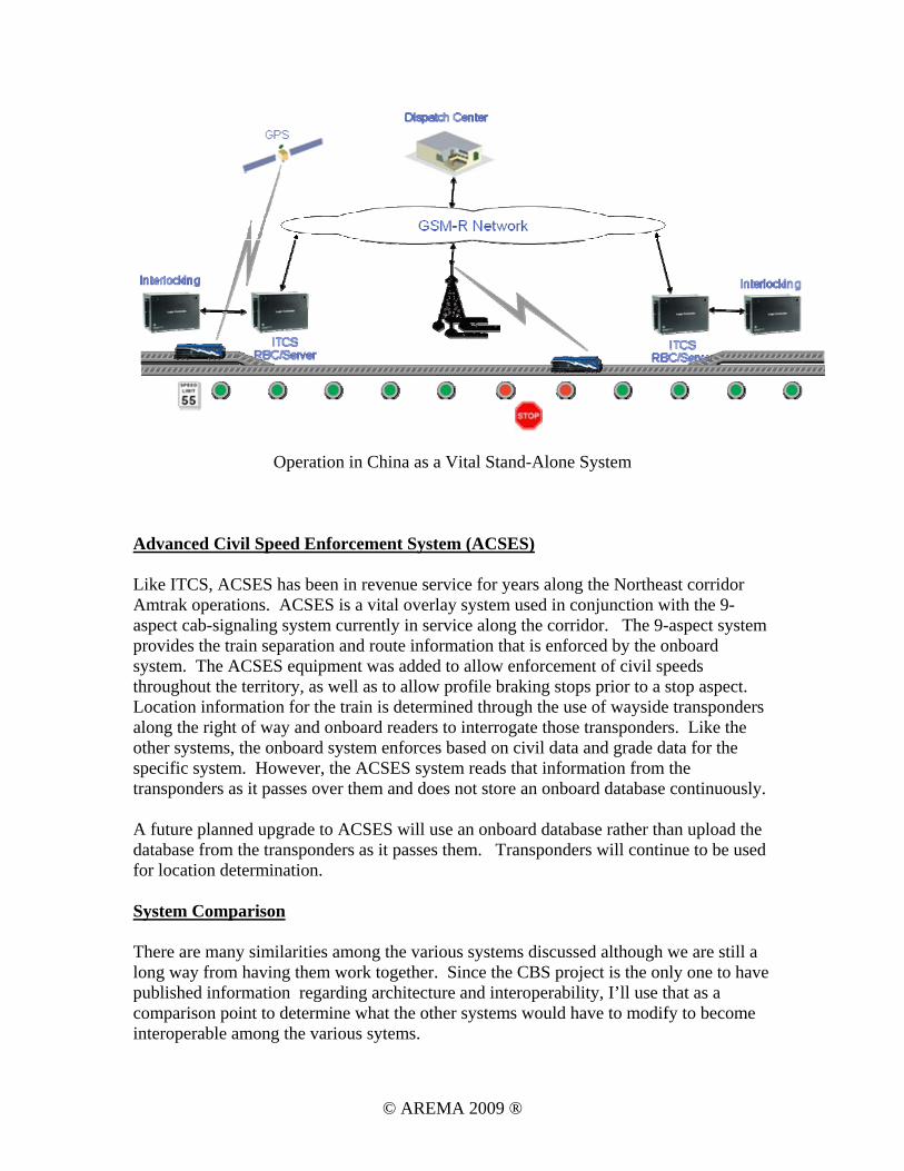
Operation in China as a Vital Stand-Alone System Advanced Civil Speed Enforcement System (ACSES) Like ITCS, ACSES has been in revenue service for years along the Northeast corridor Amtrak operations. ACSES is a vital overlay system used in conjunction with the 9-aspect cab-signaling system currently in service along the corridor. The 9-aspect system provides the train separation and route information that is enforced by the onboard system. The ACSES equipment was added to allow enforcement of civil speeds throughout the territory, as well as to allow profile braking stops prior to a stop aspect. Location information for the train is determined through the use of wayside transponders along the right of way and onboard readers to interrogate those transponders. Like the other systems, the onboard system enforces based on civil data and grade data for the specific system. However, the ACSES system reads that information from the transponders as it passes over them and does not store an onboard database continuously. A future planned upgrade to ACSES will use an onboard database rather than upload the database from the transponders as it passes them. Transponders will continue to be used for location determination. System Comparison There are many similarities among the various systems discussed although we are still a long way from having them work together. Since the CBS project is the only one to have published information regarding architecture and interoperability, I’ll use that as a comparison point to determine what the other systems would have to modify to become interoperable among the various sytems.
© AREMA 2009 ®
As a starting point, we’ll refresh that CBS uses signaling-based principles and uses virtual track circuits (i.e. occupied blocks) and virtual signals so that all territories now operate with cTc efficiency. All physical appliances in the field are uniquely identified with an ATCS address not used elsewhere in North America, The following comparisons are based on various presentations given over the years regarding the other systems as no complete documentation is available. The ITC system is still a work in progress so many of the final details are unknown. ITC and CBS One of the major differences between ITC and the other architectures is that it is operates as an overlay on existing dark territory (i.e. controlled through the use of train orders rather than signal aspects). As such, the train does not report its position in terms of block occupancies which would allow signaling logic can be used. Other differences include the encoding of signal aspects and switch positions as part of a control point message. Each of those physical appliances is unique only as part of the control point address, not unique by itself. Finally, it is not yet clear how the database used to describe the territory will be formatted. Given the use of dark territory as is, it is unlikely that the database will be formatted according to block information as done in CBS. As shown in the following chart, ITC can be used as non-vital overlays in dark territory (where the movement authorities come from a non-vital office computer) and may be used as a vital overlay in currently signaled territories where movement authorities come from the existing physical signals. ITCS and CBS ITC and CBS are very close architecturally. During the CBS demo, GETS provided their existing ITCS equipment as is, and used message translators to convert the CBS messages to the proprietary form they currently use. They also used a database translator to convert the CBS database designed for the demonstration into a form they currently use on their equipment. Overall, the differences between these two systems are relatively small and could be overcome with different message processing software and a slightly modified database design. ITCS can be used both as a vital overlay (as done in Michigan) and as a vital stand-alone system (as done in China). ACSES and CBS ACSES is designed to be used along with a traditional cab-signal system but there are still a lot of similarities in the basic civil speed architecture with CBS (and ITCS). There are similarities between the ACSES and CBS databases (as one of the ACSES system designers provided substantial help with the CBS database) so that interoperability could be achieved in that portion of the system. Since CBS is essentially a cab-signal system (using radio transmission instead of in-track transmission), the radio-based portion of CBS could be used in conjunction with ACSES.
© AREMA 2009 ®
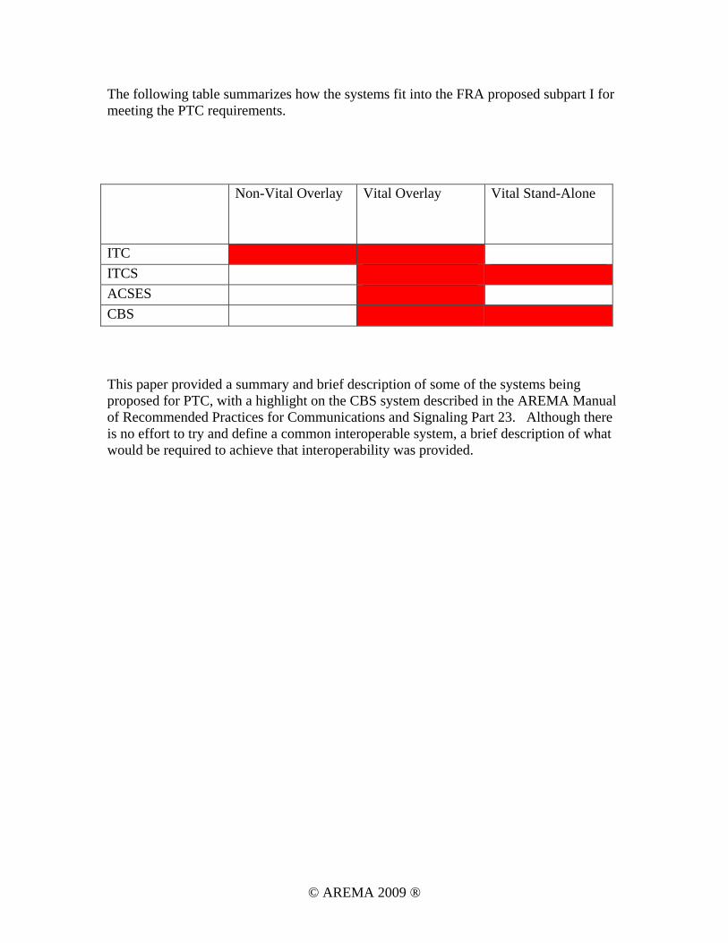
The following table summarizes how the systems fit into the FRA proposed subpart I for meeting the PTC requirements. Non-Vital Overlay Vital Overlay Vital Stand-Alone
ITC ITCS ACSES CBS This paper provided a summary and brief description of some of the systems being proposed for PTC, with a highlight on the CBS system described in the AREMA Manual of Recommended Practices for Communications and Signaling Part 23. Although there is no effort to try and define a common interoperable system, a brief description of what would be required to achieve that interoperability was provided.
© AREMA 2009 ®