introducing a systemic innovation characterized by...
TRANSCRIPT
“Introducing a systemic innovation
characterized by network externalities: the
case of The Whisper”

Author: Willem Cornelissen
S0209996
University: Twente University
School of Management and Governance
Master of Business Administration – Innovation & Entrepreneurship
Company: Twente University
Date: 11-07-2011
“Introducing a systemic innovation characterized by network externalities: the case of The
Whisper”
Supervisors: Twente University Twente University
E. Hofman H. Schiele
Capitool 15 Capitool 15
7521PL Enschede 7521PL Enschede
+31 53 489 4494 +31 53 489 5615

V
Acknowledgements
In order to finish my master Business Administration, master track Innovation and
Entrepreneurship, a research on the introduction of a systemic innovation characterized by
network externalities is conducted. The process of this master-thesis provided the opportunity
to put the theoretical background gained into practice.
As many fellow students will agree, writing your master thesis is a process of many ups and
downs, but in the end it provides a worthwhile experience. Establishing this thesis would not
be possible without the help of others. Erwin Hofman and Holger Schiele, supervisors at the
Twente University provided valuable guidance and feedback. Also thank goes out to all the
participants of the interviews for cooperating in a most benevolent way.
This thesis also marks the end of a period as a student. Without the moral support of family
and friends it would not have been the same. Special thanks goes out to Lonneke whom
support, understanding and help provided a setting from which to keep going.
While a period of student comes to an end, it is fortunate to start working on a professional
career. A career which hopefully will bring a lot of learning experiences and theory put into
practise.
Didam, July 2011


VII
Executive Summary
This report discusses the details of conducting a case study, The Whisper Bus, on introducing
a systemic innovation characterized by network externalities. The purpose of this research
was to identify the critical factors and preconditions that ensure the introduction to succeed. It
is hoped that the findings will illustrate these critical factors and preconditions, which in-turn
will lead to improvements in future introductions of systemic innovations characterized by
network externalities.
The case analyzed, included cooperation of directly involved: government, power company
and a supplier of OEM manufacturers. The time period for this study did not include the final
ending of the innovation. Hence, it was not possible to conclude whether the introduction was
successful.
Preliminary results of the research indicate that the organizations and coordination of the
introduction founding a foundation forms an appropriate coordination mechanism. It was
concluded that by adjusting the interfaces to the current infrastructure, the effects of network
externalities were largely eluded. As well as in order to break through the excess inertia a PPP
(public-private partnership) supports the founding of an installed base.
It is recommended that future research focuses on industries other than the automotive. It is
also recommended that governmental cooperation on national and international level could be
involved.

IX
Table of contents
Abstract ................................................................................................................................ 12
1. Introduction: introducing a systemic innovation characterized by network
externalities ......................................................................................................................... 13
1.1 Research approach: case study on the introduction of a systemic innovation ................ 14
1.2 Case introduction: The „Whisper bus‟ a introduced systemic innovation...................... 15
2. Research methodology: deriving a strategy for the introduction of a systemic
innovation in a market marked by network externalities ................................................. 17
2.1 Research design: testing of a theoretical model............................................................ 17
2.2 Transcribed interviews applicable for qualitative data analysis .................................... 17
2.3 Data analysis: defining between a modular architecture and an integral architecture .... 19
3. Theoretical background: outlining the concept of innovation and network
externalities ......................................................................................................................... 21
3.1 Innovation: development, improvement, adoption and commercialization of a new
process or product ............................................................................................................. 21
3.1.1 Discontinuous innovation: distinguishing radical and disruptive innovation .......... 22
3.1.2 Deducting architectural innovation to systemic innovation .................................... 24
3.2 Introducing systemic innovations: commercializing the new process, product and new
organizational structures and procedures ........................................................................... 25
3.2.1 How it works: network externalities as key to the economics of systemic innovation
...................................................................................................................................... 26
3.3 Systemic innovation: innovations that influence the product architecture of the business
system they are integrated in ............................................................................................. 28
4. Organizing systemic innovation: Consequently, system integrator need to identify
interdepencies and coordinate specifications of new interfaces ........................................ 30
4.1 Structure: centralized or decentralized structuring of the innovative process ................ 30
4.1.1 The order of control centralized or decentralized organization .............................. 30
X
4.1.2 Horizontal and vertical linkages in the complete network: coordinating suppliers
and customers ................................................................................................................ 32
4.2 Process: sequencing target directed activities............................................................... 34
4.2.1 Coordination of activities: synchronizing of interdependencies by sharing
information and adjusting throughout the entire product system..................................... 35
4.2.2 Solutions to coordination problems regarding network externalities ...................... 36
4.2.3 Incentives and governance .................................................................................... 37
4.2.4. Coping with autonomous and systemic problems ................................................. 38
4.3 Organizing a systemic innovation: the paradox of equity and non-equity alliances ...... 38
5. Empirical model determining the systemic character: FCA a product architecture
assessment ........................................................................................................................... 41
5.1 Product architecture: the function component allocation scheme ................................. 41
5.1.1 Product architecture: the function component allocation scheme ........................... 43
5.1.2 Determination of product functions and components ............................................. 44
5.1.3 Function Component Allocation schemes (FCA) .................................................. 44
5.2 Product architecture: determining interface characteristics .......................................... 45
5.2.1 Nature of interface ................................................................................................ 45
5.2.2 Interface type irreversibility .................................................................................. 46
5.2.3 Interface standardization: determining an interfaces interchangeability ................. 47
5.3 The FCA reducing product complexity across interfaces: how to cope with the
organizational network externality influence ..................................................................... 49
6. Applying the model to the Whisper: a systemic product architecture revealed ........... 50
6.1 Introducing the Whisper case: finding the right partners for the project ....................... 50
6.2 Structure of the innovation: only institutions and customers as partners ....................... 52
6.3 Describing the systemic innovation: identifying interdepencies and coordinate
specifications of new interfaces ......................................................................................... 58
6.3.1 Function component matrix: analyzing product characteristics .............................. 58
6.3.2 Product architecture assessment: defining interface characteristics ........................ 62
XI
6.3.3 Product architecture assessment: interface reversibility how deep is the component
„buried‟ in the product ................................................................................................... 63
6.4 The process of development and introduction of the Whisper bus ................................ 69
7. Summarizing and linking the findings: laboratory-type innovation process with
limited partner involvement as a challenge ....................................................................... 73
7.1 Theoretical implications: For model development and knowledge gained on systemic
innovations characterized by network externalities ............................................................ 74
7.2 Managerial implications: a general, private cooperation vital for the introduction ........ 75
7.4 Future research and limitations .................................................................................... 75
References ........................................................................................................................... 78
Appendix 1: Patent The Wheel .......................................................................................... 87
Appendix 2: Certification fuel consumption by TNO ...................................................... 102
Appendix 3: Interview protocol (Dutch) .......................................................................... 103
12
Abstract
In this study, the introduction of a systemic innovation characterized by network externalities
is examined. Conducting an in-depth case study supplemented with a theoretical study it is
observed that organizations, founding an independent entity with an independent board of
directors, improve the organization and coordination in introducing an innovation.
Additionally the research shows that a PPP proves an effective mean in order to break
through the excess inertia caused by the influence of network externalities. These findings
provide theoretical and managerial implications in the field of systemic innovation.
13
1. Introduction: introducing a systemic innovation characterized
by network externalities
Today his market economy is characterized by a continuously changing environment. Product
development and technologies are rapidly following each other and end-users are ever more
demanding. Organizations need to cope with the dynamics within their environment. Not only
by improving their existing products or technologies, also by developing new ones1. Keeping
up with the technological innovative pace, means survival for numerous organizations, being
innovative is their flow of life.
Organizations need to innovate in order to sustain or create a competitive advantage and
maintain a right of existence. This can be done through small steps on an existing basis or big
steps in unknown places.
Several projects focusing on innovation sustainable transport designs have emerged, for
instance the hybrid car. This is one of the small number of systemic innovation that do
actually make it of the drawing board into production. The studies building the theoretical
foundation of systemic innovation and or- network externalities have focused in their
theoretical and practical insights on high tech information technologies, i.e. introduction of
the mobile phone or the DVD.2 The most practical insights of how a systemic innovation can
be introduced and exploited in the automotive industry, lacks a diverse source of scientific
work. Therefore this research focuses specifically on the automotive industry, using the
„Whisper bus‟, a classic example of successful public-private cooperation.
The current literature does not provide a clear strategy to introduce a systemic innovation
characterized by network externalities. The goal of this research is to fill this scientific gap.
1 MacCormack et al. (2001). 2 Brusoni and Prencipe (2001).
14
1.1 Research approach: case study on the introduction of a systemic
innovation
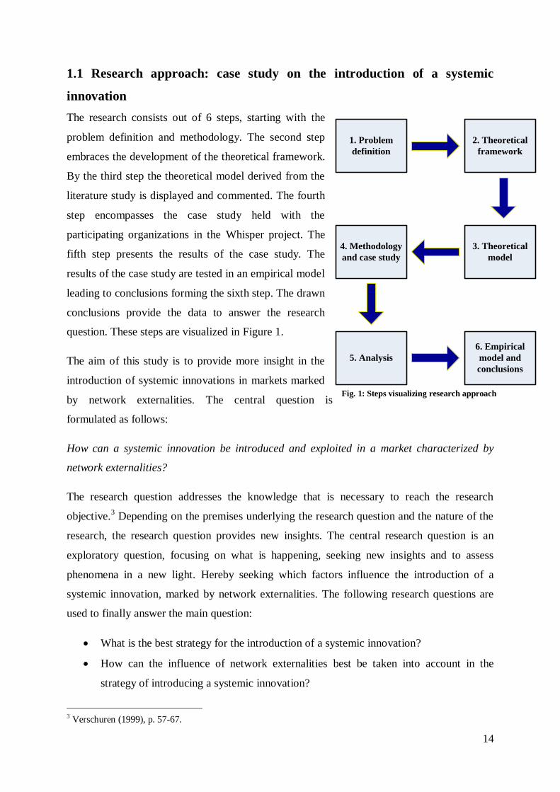
The research consists out of 6 steps, starting with the
problem definition and methodology. The second step
embraces the development of the theoretical framework.
By the third step the theoretical model derived from the
literature study is displayed and commented. The fourth
step encompasses the case study held with the
participating organizations in the Whisper project. The
fifth step presents the results of the case study. The
results of the case study are tested in an empirical model
leading to conclusions forming the sixth step. The drawn
conclusions provide the data to answer the research
question. These steps are visualized in Figure 1.
The aim of this study is to provide more insight in the
introduction of systemic innovations in markets marked
by network externalities. The central question is
formulated as follows:
How can a systemic innovation be introduced and exploited in a market characterized by
network externalities?
The research question addresses the knowledge that is necessary to reach the research
objective.3 Depending on the premises underlying the research question and the nature of the
research, the research question provides new insights. The central research question is an
exploratory question, focusing on what is happening, seeking new insights and to assess
phenomena in a new light. Hereby seeking which factors influence the introduction of a
systemic innovation, marked by network externalities. The following research questions are
used to finally answer the main question:
What is the best strategy for the introduction of a systemic innovation?
How can the influence of network externalities best be taken into account in the
strategy of introducing a systemic innovation?
3 Verschuren (1999), p. 57-67.
Fig. 1: Steps visualizing research approach
1. Problem
definition
2. Theoretical
framework
3. Theoretical
model
6. Empirical
model and
conclusions
4. Methodology
and case study
5. Analysis
15
What are the essential characteristics of the case relating it to a introduced and
exploited innovation in a governmental influenced market?
What determines The Whisper, using the Function Component Allocation scheme, as
a systemic innovation characterized by network externalities?
In accomplishing the research objective and answer the research questions, a case study is
performed on a introduced systemic innovation characterized by network externalities. This
research differs from previous research on systemic innovation due to the innovation its
network externality characterization.
Due to the inductive nature of this research a review on former literature is performed which
focussed on innovation in general and more specific systemic innovation. Next to systemic
innovation the literature research focussed on network externalities and the possible relation
and influence of network externalities on introducing innovations.
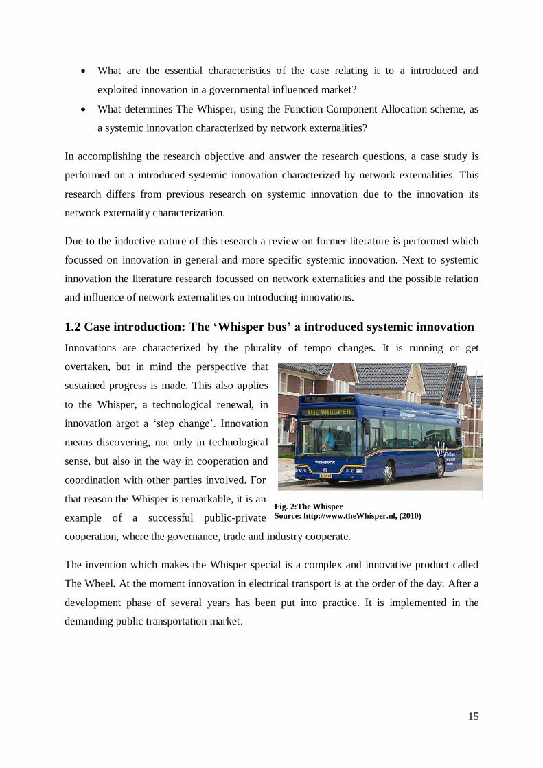
1.2 Case introduction: The „Whisper bus‟ a introduced systemic innovation
Innovations are characterized by the plurality of tempo changes. It is running or get
overtaken, but in mind the perspective that
sustained progress is made. This also applies
to the Whisper, a technological renewal, in
innovation argot a „step change‟. Innovation
means discovering, not only in technological
sense, but also in the way in cooperation and
coordination with other parties involved. For
that reason the Whisper is remarkable, it is an
example of a successful public-private
cooperation, where the governance, trade and industry cooperate.
The invention which makes the Whisper special is a complex and innovative product called
The Wheel. At the moment innovation in electrical transport is at the order of the day. After a
development phase of several years has been put into practice. It is implemented in the
demanding public transportation market.
Fig. 2:The Whisper
Source: http://www.theWhisper.nl, (2010)
16
The following three aspects make the Whisper special4:
1) The technical exceptionality of the findings applied in the Whisper;
2) The contribution they deliver against the CO2 emission problems;
3) The cooperation which has led to the definitive introduction in the public
transportation of the municipality Apeldoorn.
The Whisper will provide an expected fuel save of 50%, an emission reduction of 50% and a
noise reduction of 90%, compared to standard buses using established technologies. And a
reduction in maintenance of 80%, due to the fact that the Whisper has les parts that can wear
out. The sum of all these advantages makes the Whisper not a representation of an evolution,
but a revolution5.
4 For the patent of The Wheel see appendix: Patent The Wheel. 5 For the certification of fuel consumption by TNO appendix: Certification fuel consumption by TNO.
17
2. Research methodology: deriving a strategy for the introduction
of a systemic innovation in a market marked by network
externalities
As discussed so far, the purpose of this research is to derive a strategy for introducing a
systemic innovation influenced by network externalities. In order to do so, a case study is
conducted. This chapter clarifies the reason for performing a case study how this research is
applied to be able to answer the main research questions.
2.1 Research design: testing of a theoretical model
The starting point of this study involves: “testing of a theoretical proposition by employing of
a research strategy specifically designed for the purpose of its testing.” Therefore it is a
deductive theory. But the research is also inductive for the model created through deduction,
is “revised using data collected from qualitative research”, meaning inductive research.
Therefore the research is twofold.6
The research objective provides insight in introducing a systemic innovative product in a
market marked by network externalities. The starting point of this study is a literature research
followed by testing the cases product architecture applying a theoretical model. Critical
incidents leading to factors that are crucial are found by interviewing stakeholders. Using
these data the analytical model is tested. For that reason, the approach of this study is
exploratory.
The aim of this paper is to test a theoretical model for empirical work, in the introduction of a
systemic innovation, in markets characterized by network externalities. Prior studies in the
field of systemic innovation and network externality product introduction have focused more
on the coordination, competition and further expansion of products focused on network
externalities. As well as the automotive market has not been researched, together with public
private partnership .
2.2 Transcribed interviews applicable for qualitative data analysis
In the case study the data were collected by interviewing. Interviews are reckoned to be
essential sources of case study information:7 interviews can provide access to in-depth
insights and take place in the natural environment. The use of examples during the interviews
6 Saunders et al., (2009) p. 127. 7 Yin, (1984).
18
are limited as much as possible, in order not to influence the interviewee. Instead, the
interviewer will try to rephrase the question. This approach is chosen to let interviewees
provide data as clear as possible and not influence their point of view.
The goal of the interviews held is to gather information from the announcements of
questioned persons in order to answer one or more research questions are formulated in
advance8. Conformable the theoretical framework and the research questions are the
foundation for the interview protocol9. The opportunity of open questioning and interrogating
on answers are other interview features. The interviewer takes an objective and impartial
position in order to ensure that the questions are not aiming in a certain direction10
. In the
interview protocol the majority of the questions in the interview protocol are open questions.
Open questions are labour-intensive, but for the interviewee it is a stimulation to talk freely11
.
Especially when there is little known about the expected answers, open questions are
appropriate.
The conducting of the interviews took place face-to-face. With the advantage that each
interviewee is interviewed in their natural environment, leading to enhanced communication.
Information is gathered about matters or persons outside the interviewees, therefore the
interviewees in this research can be described as informants12
. Both internal and external
informants/project participants are interviewed in order to obtain more valuable data. If
possible in different function levels participants were interviewed in order to obtain possible
differences in insights among function levels. This is applied within the municipality of
Apeldoorn and e-Traction. The length of interviews differed, some participants scheduled an
hour, others were not time-bound.
8 Emans (2002).
9 Appendix: interview protocol. 10 Emans (2002). 11 Yin (1984). 12 Verschuren and Doorewaard (2005).
19
To assure effective data collection, recordings are used to provide the most accurate rendition
of the interview.13
During the transcription seven guidelines14
apply, the three most important
are:
1. “Preserve the morphologic naturalness of transcription. Keep word forms, the form of
commentaries, and the use of punctuation as close as possible to speech presentation and
consistent with what is typically acceptable in written text.”
2. “The transcript should be an exact reproduction. Generate a verbatim account. Do no
prematurely reduce text.”
3. “The transcription rules should be complete. Transcribers should require only these rules
to prepare transcripts. Everyday language competence rather than specific knowledge (e.g.
linguistic theories) should be required.”
In accordance to the guidelines all the interviews were digitally recorded and entirely
transcribed by the interviewer in same standardized manner. To ensure confidentiality all
transcripts were only accessible for the researcher. Each digital recording is saved, in order to
enable the possibility of listening back in case of unclearness. The informants all gave
permission for the use of the data, one of the respondents asked for a confidential treatment of
his statements.
2.3 Data analysis: defining between a modular architecture and an integral
architecture
From the data gathered from the transcribed interviews and additional literature the Design
Structure Matrix (DSM) model is applied to reveal the innovation its systemic character. The
model is designed around the Design Structure Matrix (DSM), developed by Pimmler and
Eppinger15
and expanded by Fixson16
. The technique of DSM is originally developed for
better understating system engineering needs which arise due to complex interactions between
components.
In order to develop a product architecture description that is comprehensive and meanwhile
operational, defined as: “A modular architecture includes a one-to-one mapping from
functional elements to physical components of the product, and specifies de-coupled
13 McLellan, (2003), p.64. 14 McLellan, (2003), p.65. 15 Pimmler and Eppinger, (1994). 16 Fixson, (2005; 2008).
20
interfaces between components. An integral architecture includes a complex (non one-to-one)
mapping from function elements to physical components and/or coupled interfaces between
components”17
. The information obtained from this design is used to define the product
architecture. Roughly the method consists out of three steps: 1) Decomposing the system into
elements: describe the product concept in terms of functional and/or physical elements
achieving the products functions. 2) Document the interaction between the elements:
identifying the interactions which may occur between functional and physical elements. 3)
Cluster elements into chunks: The elements are clustered into chunks based on criteria set by
the overall product design strategy. These chunks define the product architecture18
.
17 Ulrich (1995), p.422. 18 Pimmler and Eppinger (1994).
21
3. Theoretical background: outlining the concept of innovation
and network externalities
The theoretical framework presented, will start elaborating on the different types of
innovation recognized in the literature. Subsequently focusing on the main terms in this
research; systemic innovation and network externalities and the factors which characterize
them.
3.1 Innovation: development, improvement, adoption and
commercialization of a new process or product
As already mentioned in the problem definition, today´s market economy is characterized by
a continuous changing environment, and organizations need to innovate in order to sustain
some form of competitive advantage. In the field of innovation a lot of different definitions
are used to label the type of innovation discussed. In order to define types of innovations, a
clear definition of innovation is inevitable.
Starting with the distinction between an innovation and an invention. An innovation is a
discovery of serve nature, that goes no further than the laboratory, is an invention. If the
discovery moves further into the process and adds economic value, whether it is positive or
negative, is marked an innovation. So, when this idea is developed and eventually taken into
production, whether it becomes successful or not, an innovation is at hand. The discovery or
idea generation can be initiated in almost every layer of the organization and by any
employee, whether top-management or blue collar employee. A clear definition of innovation
is:19
“innovation is an iterative process initiated by the perception of a new market and/or new
service opportunity for a technology-based invention which leads to development, production
and marketing tasks striving for the commercial success of the invention”. A comprehensive
review of the innovation literature is provided by Jordan and Teece:20
“Innovation is the
search for, and the discovery, development, improvement, adoption and commercialization of
new processes, new products, and new organizational structures and procedures.” The
scholars further note that “It is an activity in which “dry holes” and “blind alleys” are the rule,
not the exception.”21
19 Garcia and Galantone (2002), p. 112. 20 Jordan and Teece (1990), p.75. 21 Jorde and Teece (1990), p.76.
22
As defined an innovation is not just a product or task on its own, but a process. This process
can have very different initiations and outcomes, depending on the innovation type and how
the innovation is examined. An innovation can be experienced as just a minor change on an
existing product or service by a manufacturer, but completely new by an end-user. The
difference is made by the state of the knowledge of the actor who is perceiving the innovation.
The literature22
distinguishes four different focuses of innovation describing pathways that an
innovator can use in his search for good ideas. The first focus of innovation is the
improvement or development of products or services (product innovation), for instance a new
mobile phone. The second focus is the improvement of partly or the whole process of an
organization (process innovation),for example the use of Lean Management. The third focus
is the repositioning of a product or service to create new markets (positioning innovation), the
Swiss watch industry struggled in the transition from mechanical to digital watches but
eventually the industry re-vitalized by the positioning of the watch as a luxury good. The
fourth and last change (paradigm innovation), for example the global change towards durable
energy.
By making the distinction between innovation and invention and defining innovation and
recognizing innovation not only as a product but as a process being able to further
characterize and define innovation towards systemic innovation. The next step is making the
distinction of discontinuous innovation in radical and disruptive innovation.
3.1.1 Discontinuous innovation: distinguishing radical and disruptive innovation
One of the first scholars to use the disruptive innovation concept is Christensen23
differentiating between sustaining and disruptive innovation- based on technological
performance and market segmentations. Technologies that help companies to sustain their
growth in the existing or established market place in order to ensure market growth and
domination focusing on improvement on the performance of current products and services is
referred to as sustaining innovation. These improvements are incremental or radical.
“Disruptive innovation” occurs when this new product, entering the market at a lower level of
sophistication, rapidly progresses to meet the needs of the majority of consumers in the
marketplace and, as a result, captures market share from well established firms.”24
Established
22 Tidd, Bessant and Pavitt (1999). 23 Christensen (1997) 24 Bower & Christensen (1996), p.45.
23
firms serving the more attractive segments ignore a disruptive technology, because it only
serves a small low-marging market.25
„„Disruptive technologies are typically simpler, cheaper,
and more reliable and convenient than established technologies.‟‟26
A disruptive technology is
distinctively introduced in a new market with lower demands or at the low-end-side of an
existing market.
Radical innovations which change core technical concepts and their linkages lead to adaptive
challenges for organizations.27
The radical innovation concept differentiates between
incremental and radical innovation through a clear delineation of the technological features
that are commercialized, either in new- or existing markets.28
A radical innovation contains at
least one of the following characteristics:29
To create improvements in known performance features;
To create an entirely new set of performance features;
To significantly reduce costs.
These characteristics promote radical innovation as a means of gaining and sustaining
competitive advantages for established firms to create growth potential. Radical innovations
aim at a high-end market, containing users that search for superior performance features and
not the cheapest solution. Therefore judging the innovations performance over price.
Examining the potentials30
, the first should be interpreted as based on the current performance
features of a product or process, where a huge step can be taken when the radical innovation
is applied. The second potential should be interpreted as a set of performance features that
have an entirely new potential to outrun the existing products or processes. The third and last
potential makes it possible to significantly reduce costs but not affecting the performance
characteristics.
Disruptive and radical innovations have a strong resemblance with the difference that lies in
the change of performance characteristics. A radical innovation reduces costs without
affecting the current performance features, whereas disruptive innovation changes both. The
25 Christensen (2000). 26
Christensen (2000), p. 192. 27 Tushman and Anderson (1986). 28 Leifer (2000). 29 Leifer (2000), p.5. 30 Leiffer (2000).
24
core principle of a disruptive innovation is that it satisfies demands for a product with a low
price and performance features which do not need to be the same as of existing products. A
conceptualization of the major difference in the perception of the end-user, the market.
“Radical innovations typically enter the marketplace at the higher-end where performance is
more important than cost. Subsequently, with sustaining innovations, they could rapidly
reduce cost and capture the mass markets. Disruptive innovations, on the other hand, are
typically targeted at the low-end customers, or new markets where the need is not satisfied in
the past (competition against “non-consumption”) and hence any product which could “do the
job” and yet affordable could sell.”31
“A disruptive innovation is applicable on the low-end side of an existing market or a new
market which has much lower demands on performance and different price perceptions. A
radical innovation is typically applicable on high-end side of an existing market or a new
market with higher demands on performance.”
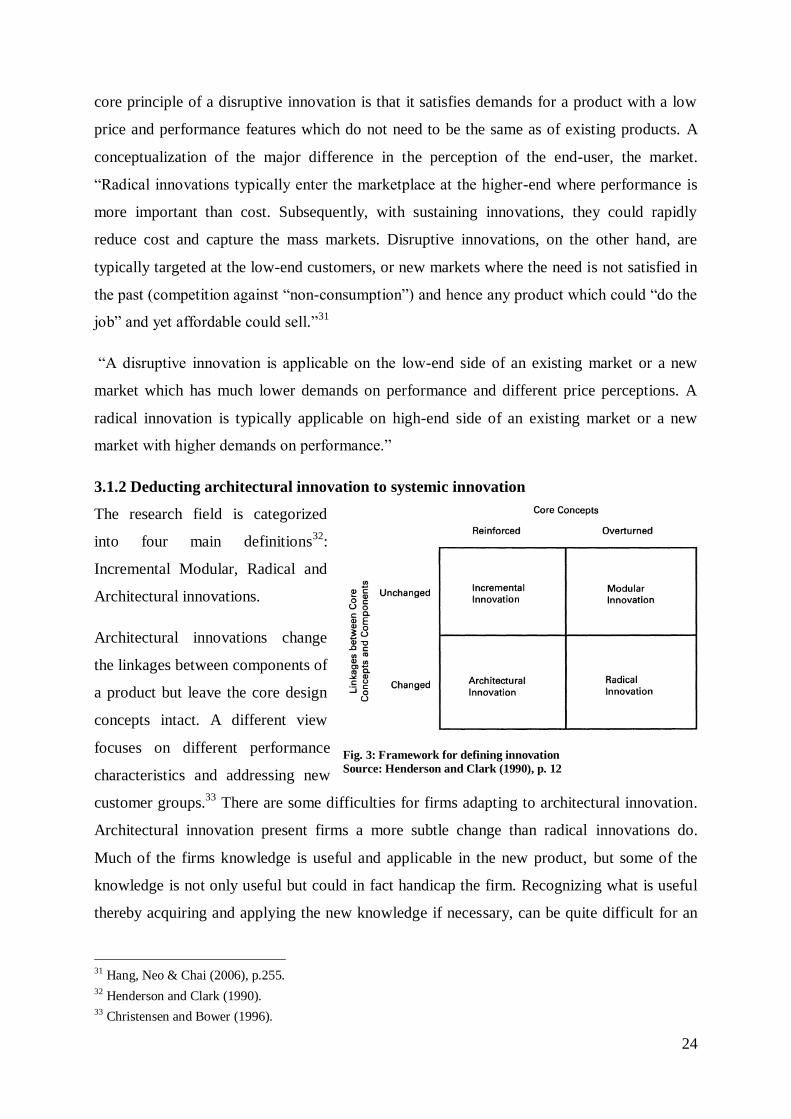
3.1.2 Deducting architectural innovation to systemic innovation
The research field is categorized
into four main definitions32
:
Incremental Modular, Radical and
Architectural innovations.
Architectural innovations change
the linkages between components of
a product but leave the core design
concepts intact. A different view
focuses on different performance
characteristics and addressing new
customer groups.33
There are some difficulties for firms adapting to architectural innovation.
Architectural innovation present firms a more subtle change than radical innovations do.
Much of the firms knowledge is useful and applicable in the new product, but some of the
knowledge is not only useful but could in fact handicap the firm. Recognizing what is useful
thereby acquiring and applying the new knowledge if necessary, can be quite difficult for an
31 Hang, Neo & Chai (2006), p.255. 32 Henderson and Clark (1990). 33 Christensen and Bower (1996).
Fig. 3: Framework for defining innovation
Source: Henderson and Clark (1990), p. 12
25
established firm on account of the way knowledge and especially architectural knowledge, is
organized and managed.
Different authors have defined architectural innovation in different ways. “Architectural
innovation is often triggered by a change in a component-perhaps size or some other
subsidiary parameter of its design-that creates new interactions and new linkages with other
components in the established product”.34
A similar definition focuses on changes in (at least)
one component which requires substantial modification in components throughout the system
(most often in terms of physical properties such as volume and area).35
Based on the amount of integrative efforts, or the coupling of activities, that is required in a
development is a stronger related to product complexity than technological change.36
A
distinction can be made between the characterization of the development process in systemic
and analysable complexities. “Systemic complexities refers to situations when the
development task comprises severe and unforeseeable technical interdependencies, something
that makes separation and specialisation difficult.”37
The last to be added to the innovations
list is systemic innovation, meaning: innovations requiring considerable adjustments in other
parts of the business system they are integrated in.38
3.2 Introducing systemic innovations: commercializing the new process,
product and new organizational structures and procedures
There is a distinction in the characterization of the development process between analysable
and systemic complexities. Systemic innovation is a specific type of technological change,
operating through a specific mechanism and has specific consequences.
The amount of integrative efforts, or the coupling of activities- required in a development, is
stronger related to product complexity than technological change.39
Dividing the
characterization of the development process in systemic and analysable complexities:
“Systemic complexities refers to situations when the development task comprises severe and
unforeseeable technical interdependencies, something that makes separation and
34 Henderson and Clark (1990) , p.12. 35
Langlois (1988). 36 Lindkvist et al. (1998). 37 Magnusson et al. ( 2003), p. 7. 38 See Teece (1986), Chesbrough and Teece (1996) as well as Brusoni and Prencipe (2001). 39 Lindkvist et al., (1998).
26
specialisation difficult.”40
A different characterization views a systemic innovations a as an
innovation that requires interrelated changes in product design, supplier management,
information technology.41
In this paper the following definition applies: innovations that
require significant adjustments in other parts of the business system they are embedded in.42
3.2.1 How it works: network externalities as key to the economics of systemic innovation
A number of product-related dimensions have been linked to NPD outcomes are expected to
have a diverse effect on performance, which is dependable on the degree of innovativeness of
the product.43
Demonstrated product superiority is an example of these product-related
dimensions. For discontinuous innovations, a clear example of incorporating a new
technology to handle customer/environmental concerns in a more effective way, in providing
a significant comparative advantage in order to secure adoption by customers. A pitfall in
which companies can step is the overenthusiastic focus on technological advances resulting in
the development of refined, though costly, solutions to relatively simple, non-existent or non-
core problems. The focus on product superiority is more important than in continuous
innovation since producers face a lower purchase risk when applying/purchasing a continuous
innovation.
Although much has been written about systemic innovation, there has been little focus on the
introduction of systemic innovation in products marked by network externalities in the
automotive industry. The force of network externalities shows that interdependent demand
can sustain continual growth in a static population with a static income.44
The mechanism
works as follows. “New subscribers join. This increases the incremental utility of the service
and induces marginal nonusers to join. That in turn induces further growth etc., etc.”45
New network externality products often face coordination problems because the installed base
and the complementary goods that add product value are not available yet.46
The installed
base can also be defined as “an “equilibrium user set”, a set of users consistent with all
individuals (consisting out of users and nonusers) maximizing their utilities.”47
An installed
40 Magnusson et al., (2002), p.7. 41 Chesbrough and Teece, (1996). 42 See Teece (1986); Chesbrough and Teece (1996); as well as De Laat (1999). 43 Brentani (2001). 44 Rohlfs (1974). 45 Rohlfs, (1974), p. 18. 46 Dew and Read (2007). 47 Rohlfs (1974), p. 16.
27
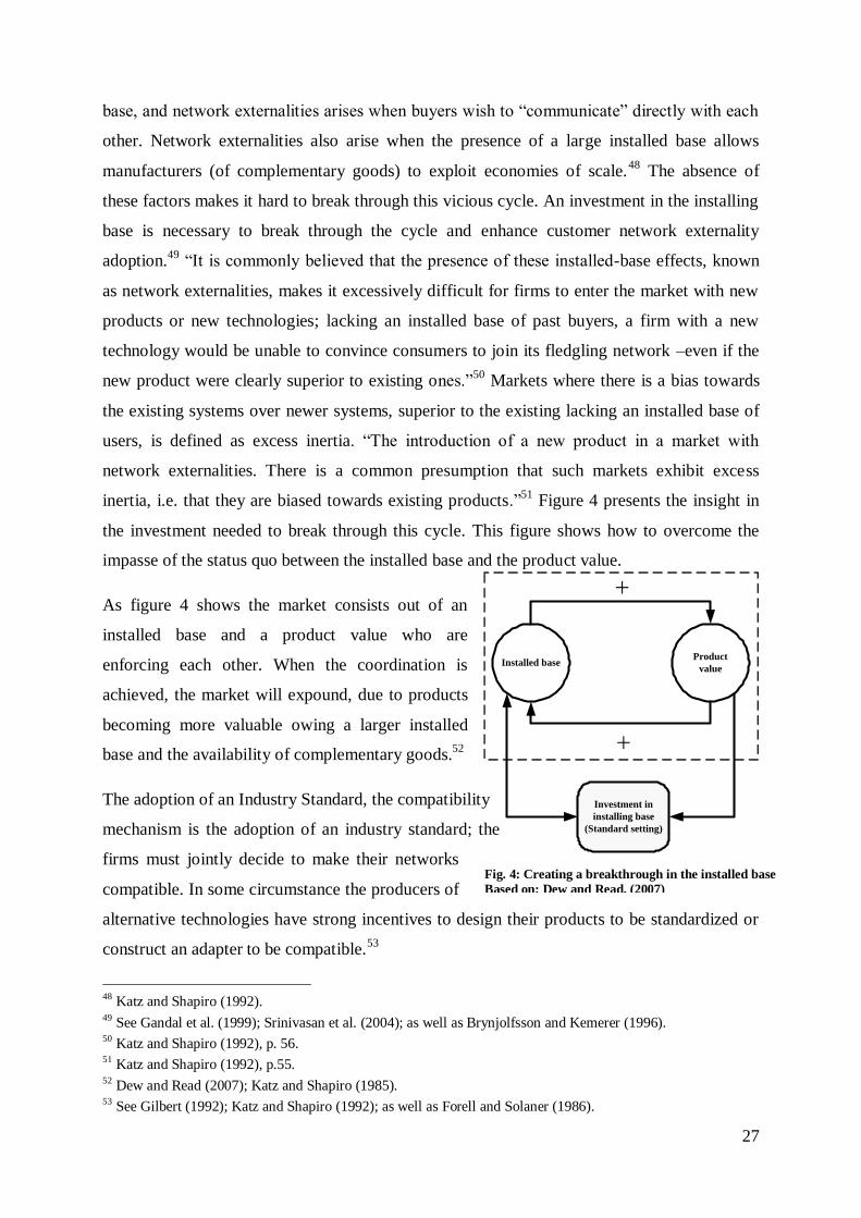
Fig. 4: Creating a breakthrough in the installed base
Based on: Dew and Read, (2007)
Installed baseProduct
value
Investment in
installing base
(Standard setting)
base, and network externalities arises when buyers wish to “communicate” directly with each
other. Network externalities also arise when the presence of a large installed base allows
manufacturers (of complementary goods) to exploit economies of scale.48
The absence of
these factors makes it hard to break through this vicious cycle. An investment in the installing
base is necessary to break through the cycle and enhance customer network externality
adoption.49
“It is commonly believed that the presence of these installed-base effects, known
as network externalities, makes it excessively difficult for firms to enter the market with new
products or new technologies; lacking an installed base of past buyers, a firm with a new
technology would be unable to convince consumers to join its fledgling network –even if the
new product were clearly superior to existing ones.”50
Markets where there is a bias towards
the existing systems over newer systems, superior to the existing lacking an installed base of
users, is defined as excess inertia. “The introduction of a new product in a market with
network externalities. There is a common presumption that such markets exhibit excess
inertia, i.e. that they are biased towards existing products.”51
Figure 4 presents the insight in
the investment needed to break through this cycle. This figure shows how to overcome the
impasse of the status quo between the installed base and the product value.
As figure 4 shows the market consists out of an
installed base and a product value who are
enforcing each other. When the coordination is
achieved, the market will expound, due to products
becoming more valuable owing a larger installed
base and the availability of complementary goods.52
The adoption of an Industry Standard, the compatibility
mechanism is the adoption of an industry standard; the
firms must jointly decide to make their networks
compatible. In some circumstance the producers of
alternative technologies have strong incentives to design their products to be standardized or
construct an adapter to be compatible.53
48 Katz and Shapiro (1992). 49 See Gandal et al. (1999); Srinivasan et al. (2004); as well as Brynjolfsson and Kemerer (1996). 50 Katz and Shapiro (1992), p. 56. 51 Katz and Shapiro (1992), p.55. 52 Dew and Read (2007); Katz and Shapiro (1985). 53 See Gilbert (1992); Katz and Shapiro (1992); as well as Forell and Solaner (1986).
28
Recapitulating, new network externality products often face coordination problems due to the
lack of an installed base or an equilibrium user set. Breaking through this so-called excess
inertia is possible when a subsequent investment in the installed base has been made or when
producers of alternative products make their products compatible to the new product.
3.3 Systemic innovation: innovations that influence the product
architecture of the business system they are integrated in
It is clear that the concept of innovation is an idiosyncratic definition. “An iterative process
initiated by the perception of a new market and/or new service opportunity for a technology-
based invention which leads to development, production and marketing tasks striving for the
commercial success of the invention.”54
The concept of innovation is further deducted into systemic innovation. Systemic innovation
is characterized by changes which are not known on forehand, in one or more components,
requiring substantial modification in components throughout the system.55
Based on foregoing
definitions in this paper defines systemic innovation as: ”innovations that require significant
adjustments in other parts of the business system they are embedded in.”56
The systemic nature of innovation, combined with the uncertainty that it brings, makes it a
challenge for organizations to manage the process as correct as possible. Systemic innovation
being dominant in the development of complex products, and parts of complex products, with
products consisting out of many interrelated components and subsystems. Resulting in
components which scarcely can be changed without requiring changes to other parts of the
product. In this systemic context it is an organizational challenge for innovating organizations
to develop and renew product systems. The organizational and managerial capability to deal
with these issues of systemic innovation in the literature referred to as systems integration.
The new product architecture is developed in a way that existing product systems can be
attached in the light of component innovation, or modular innovations. The remark/approach
„firms more than they make‟ stimulates firms to monitor and absorb these external
technological developments.57
Integrating this external knowledge provides organizations
54 See Farell and Solaner (1986); Gilbert (1992); as well as Katz and Shapiro (1992). 55 Langlois (1988). 56 Markku et al. (2005), p.3. 57 Brusoni and Prencipe (2001).
29
with detailed architectural knowledge on component or modular interrelationships. This
knowledge is the heart of their systems integration capability.58
Systems integrators need to monitor modular component innovations, which are based on
existing interfaces, in order to learn about possible imbalances and what technological
changes are required to other components.59
Whereas architectural cannot readily be
implemented in the product system due to required interface changes.60
Consequently, a
system integrator needs to identify interdepencies and coordinate specifications of new
interfaces. The intensive exchange of coordinative information is needed in designing new
interface specifications.61
Therefore there should be close links with, for instance, specialized suppliers as well as the
monitoring of technological innovations in other industries. This refers to the importance of
vertical and horizontal linkages.
58 Van den Ende et al. (2008). 59 Van den Ende et al. (2008). 60 Van den Ende et al. (2008). 61 Van den Ende et al. (2008).
30
4. Organizing systemic innovation: Consequently, system
integrator need to identify interdepencies and coordinate
specifications of new interfaces
In organizing a systemic innovation there are several core issues forming the pillars. The first
area focuses on describing the characteristics of a systemic innovation. The second focus area
is the structure and linkages that organizations have and need to use for organizing the
innovative process. The final pillar consists out of the coordination of activities and how to
deal with coordination problems.
4.1 Structure: centralized or decentralized structuring of the innovative
process
Paragraph 4.1 focuses on structuring the firm organization when managing the innovation
process. In structuring these innovations there are two major distinctions the centralized and
decentralized organization, and horizontal and vertical linkages.
4.1.1 The order of control centralized or decentralized organization
Systemic innovation projects have to generate the architectural knowledge on how technology
suppliers and other parties can be best interconnected. Because different components have
never been combined before, this makes it difficult to specify and develop the component
interfaces. Upfront little is known about how components will interact and how they can be
adapted in order to create a consistent system.62
The academic literature structures the firm organization of innovating in a systemic way in
centralized and the decentralized organization. Several scholars argue that the only firms that
can innovate in a systemic way are strong and integrated, following the internal
organization.63
Coalitions consisting of joint ventures, alliances or virtual partners will not be
able to create a systemic innovation nor be able to set standards or control further evolution.
Integration of all necessary activities into the corporation is the only organizational solution
that will make the grade when introducing and exploiting a systemic innovation.64
Network
alliances are regarded only useful when it concerns an autonomous innovation. Main
argument for holding on to the single firm position is the order of control. The integrated firm
62 Jaspers (2009). 63 Teece (1996). 64 Chesbrough and Teece (1996).
31
is to be considered as the strongest form of control.65
The virtual company, holding together a
bundle of outsourced activities is supporting the internal organization, which is perceived to
enclose the least amount of control.66
Decentralized organization of innovating in a systemic way is derived from the internal
organization. It differs to internal organization, unless there is a leading firm in the network,
perceived as to be almost as strong as an integrated corporation.67
Recapitulating the view of
the single-integrated corporation form it argues that alliances are not appropriate
arrangements to innovate in a systemic fashion. Because it is not capable to innovate in a
systemic fashion, nor to set systemic standards or further develop a new technological
regime.68
The centralized organization lies between the internal organization and
decentralized organization. The common forms such as strategic alliances and joint ventures,
may almost rate as strong control when there is a leading firm.69
The strongest critics enclose
that companies may be reluctant to make the necessary transaction-specific investments out of
fear that advantage is taken of it and tacit knowledge sharing is obstructed.70
Opposed to the internal organized systemic innovation scholars argue that industrial structure
is changing from vertical to horizontal and digital convergence is taking place. In this light
systemic innovation can only be undertaken by alliance networks. Although these networks
are vulnerable to opportunism, relations can be established through both substantial and
procedural commitment. Industry standards can be set by expanding the alliance network.71
Companies seem to undergo a transition from a vertical to a horizontal structure. Faced with
new competitors, companies are forced to move into broader terrain, due to the risk of being
outcompeted. The necessity of keeping up to date with the technological developments,
alliances across industrial boundaries becomes more common.72
This trend seems to enhance
the decentralized cooperation and cooperation through horizontal linkages.
Recapitulated the academic literature regards two main organizational structures, the
centralized and the decentralized organization. The centralized organization consisting out of
65 De Laat (1999). 66 Chesbrough and Teece (1996). 67 Chesbrough, Teece (1996). 68
See Teece (1984); Teece (1986); as well as Teece (1996). 69 De Laat (1999). 70 De Laat (1999). 71 Yoffie, (1997); De Laat (1999). 72 Yoffie (1997).
32
a singular organization and the decentralized organizational structure. The accessing of new
or alternative competences and knowledge bases in the market, thereby mitigating the risk of
technological obsolescence empowers the decentralized organizational structure.
4.1.2 Horizontal and vertical linkages in the complete network: coordinating suppliers
and customers
Horizontal and vertical linkages are inevitable when coping with a systemic innovation.
Especially in the level of interdependence between the supplier organizations and the setting
in which the innovation needs to be implemented. Systemic innovation projects have to
generate the linkages between the components and subsystems, hence they cannot use the
path followed by existing products.
The vertical structure and associated links to external suppliers can have a direct influence on
its innovative activities.73
There are different views regarding the effects of technological
uncertainty on firms‟ integration decisions, whether uncertainty leads to integration or
disintegration at firm level.74
In the cooperation using vertical linkages the focus lies on Transaction Costs (TCE). The
major sources of transaction costs in the literature are: uncertainty, frequency of contract
updates, asset specificity physical, human, site and dedicated assets.75
Higher uncertainty
leading to higher transaction costs. Hence, firms will organize their boundaries to minimize
these costs. Vertical integration prevents unnecessary bargaining and uses authority to
harmonize interests, risk perception, expectations and resource allocation.76
Therefore, higher
uncertainty will lead to higher degrees of vertical integration in an industry. Internal
organization moderates these problems cope with uncertainty by using gradually adjusting
decisions.77
Next to the TCE, there is the Knowledge Based View (KBV) which explicitly argues that the
reason of existence for organizations is the efficient transfer and creation of information and
know-how. KBV involves higher-order routines, knowledge, skills and learning and are the
result of organizational components following each other.78
According to the KBV, firms in
73 Teece (1996). 74 Walker and Weber (1987); Schilling and Steensma (2002); as well as Hoetker (2005). 75 Williamson (1983). 76 Wolter and Veloso (2007). 77 Langlois (1988). 78 Langlois (1988); Madhok (2002).
33
an innovative environment which is characterized by technological uncertainty internalize
activities not because of disadvantages (transaction costs), but because of the benefits of
coordinating preceded by and within the same organization complementary- and similar
activities.79
These advantages are created because organizations develop routines and language tools
through training. These routines become efficient in transferring knowledge and tackling tasks
that require quick adaption .80
The presence of technological uncertainty might lead to parties
(unintentionally) keeping knowledge private, being related to the presence of high degrees of
tacit knowledge. Because tacit knowledge can more easily be transferred within an
organization, vertical integration would be the outcome to prevent the leakage of
knowledge.81
When customers are underserved by a technology with an uncertain future, firms are
constantly trying to evolve the products with interdependent designs.82
Arguing that this
interdependency, which comes down to interfaces within the product architecture that are not
well specified, leading to changes in design specifications can easily affect additional ones.
This involves a lot of tacit knowledge and requires unstructured technical dialog, best
performed in a single organization. Organizations with upstream capabilities and high risk of
obsolescence have low incentives for vertical disintegration.83
Where-as systemic innovations
where coordination needs and transaction costs as well as the incentives for vertical
integration are high.
In general the purpose of horizontal collaboration is to carry out basic research and establish
standards.84
Firms are likely to work with competitors when they share common problems
that are outside the area influenced by the competitor.85
Another incentive aligning with
competitors can be pre-competitive research programs.86
This type of collaboration does not
seem to be the most appropriate mechanism in achieving productive innovations.87
The
79 Wolter and Veloso (2007). 80 Langlois (1988); Hoetker (2005). 81 Christensen, Verlinden and Westerman (2002); Teece (1982). 82 Christensen, Verlinden and Westerman (2002). 83
Wolters and Veloso (2007). 84 Tether (2002); Bayona et al. (2003). 85 Tether (2002). 86 Nieto et al. (2007). 87 Bayona et al. (2003).
34
problems of information leakage and the risk of hold up are greater when working with
competitors. Which can be decisive in the a firm his cost-benefit analysis against
collaborating with competitors when the firms objective is to achieve product innovations,
even more when concerning innovations with a high degree of novelty.88
In their research
using data from a longitudinal sample of Spanish manufacturing firms the conclusion is drawn
that collaborating with competitors turns out to be the least fruitful way of producing novel
innovations.89
This conclusion is consistent with earlier studies which highlights performing
basic research and establishing standards as reasons for collaborating with competitors.90
More recent research performed supports the statement that collaborating with competitors
has a negative effect on innovation, found that collaboration with competitors are associated
with lower product innovation in the firm.91
Who are reluctant to share knowledge due to the
threat of unexpected transfer of knowledge and therefore become more careful regarding the
knowledge shared.92
Opportunistic behaviour is usually less within hierarchies, because transactions tend to take
place in formalized ways.93
Hierarchies will not eliminate all opportunistic behaviour, because
organizational politics or abdicating on jobs hinder coordination. An equity alliance would be
able to counter these negative effects. “Some characteristics that equity alliances share with
hierarchies appear to deter opportunistic behaviour: aligned interests, monolithic control, and
diminished performance ambiguity.”94
4.2 Process: sequencing target directed activities
The process comprises out of the coordination of activities. The coordinated activities can
result in coordination problems regarding network externalities. How to cope with these
autonomous and systemic coordination problems be answered. As well as incentives and
governance. And finally deriving a framework for analysis using the Function Component
Allocation scheme (FCA).
88 Nieto et al. (2007). 89 Nieto et al. (2007). 90
Tether (2002); Bayona et al. (2003). 91 Annique Un et al. (2010). 92 Annique Un et al. (2010); Hamel (1991). 93 Gulati (1995). 94 Kale and Singh (2009), p. 48.
35
4.2.1 Coordination of activities: synchronizing of interdependencies by sharing
information and adjusting throughout the entire product system
Systemic innovation projects have to generate the architectural knowledge on how technology
suppliers and other parties can be best interconnected. Contradictory development projects or
autonomous innovations can benefit from the existing capabilities. The different components
have never been combined before, this makes it difficult to specify and develop the
component interfaces. Upfront little is known about how components will interact and how
they can be adapted in order to create a consistent system.
By their very nature, systemic innovations require information sharing and coordinated
adjustment throughout an entire product system.95
In the “old model”, closed innovation,
where coordination often only takes place with supplies and customers. In the open
innovation model, with systemic innovation processes firms need to coordinate both vertically
with producers (of complementary products) as horizontal with direct competitors to ensure
that the innovation is viable.
Coordination integration referred to as the extent of information exchange between two stages
of production to achieve so-called „unity of effort‟.96
In this context it is defined as the extent
of information exchange between the system firm and the implementing firm to make sure
that the component fits into the whole system. A high degree of coordination, integration is
needed if the component is highly interdependent with other components in the product.97
In
this situation of systemic innovation, intense information-processing is needed, for instance
by mutual adjustment and coordination between the teams.98
This coordination can be lower
or performed without any information-processing, referred to as low coordination integration,
when the new component operates in an environment of existing interfaces.99
Though related,
it is important to make a distinction between coordination integration and ownership
integration.100
Further identifying that information processing occurs within the system firm
when it involves an internal project, but when information processing takes place across firm
boundaries when external projects have to be coordinated. The extent of processing
95 See Chesbrough and Teece (2002); Langlois and Robertson (1991); as well as Maula et al. (2005). 96
Lawrence and Lorsch (1967). 97 Brusoni et al. (2001). 98 Chesbrough and Teece (1996); Dew and Read (2007). 99 Brusoni et al. (2001). 100 Robertson and Langlois (1995).
36
information between the system firm and the component development project, reflects the
strength of the tie between the two organizations.
Without tight „coordination integration‟ interdepencies might not be discovered until
architectural problems arise in later stages of the development process.101
Furthermore,
internal coordination is vital to effectively coordinate supplier relationships, especially in the
start-up phase.102
4.2.2 Solutions to coordination problems regarding network externalities
Several tools exist for increasing product value to the consumer and accelerating adoption.103
The first is price reduction,104
changing product attributes and waiting for time to pass by.
Criticizers105
argue that price reduction would kick-start the adoption on the short run, but it
puts pressure on the profitability for suppliers and form a low price ceiling. The change of
product attributes is hard, especially in a network externality setting, because some attributes
not only affect suppliers but also producers of complementary goods. Waiting would provide
competitors time to market and product obsolescence could enter.106
In order to break through the excess inertia the literature provides three main tools:
standardization, alliances and leadership. According to the standardization literature setting
technology standards accelerates adoption, because standardization reduces the risk of product
incompatibility.107
A huge number of standard-setting organizations exist and also the role of
government-sponsorship in some form has accompanied standards.108
Secondly supply-side
alliances are a mechanism for the acceleration of adoption.109
Cooperation with potential
rivals (horizontal cooperation) is also a way of reducing the number of standards on the
market. Alliances can also help with introducing complementary goods who build the
perception of a critical mass around a product. Leadership, mostly given by those with market
power in their industries and lead adopter those which are decisive in which innovation gets
adopted are coordinating points. It may seem that leaders are using economical and political
101 Robertson and Langlois (1995). 102 Takeishi (2001). 103 Dew and Read (2007). 104 Dranove and Gandal (2003). 105
Dew and Read (2007). 106 Dew and Read (2007). 107 Tassey (2000). 108 Swann (2000). 109 Tsoutsos and Stamboulis, (2005).
37
power to enforce the innovation but they can be useful in setting the standard in a market with
a scattered set of actors.110
4.2.3 Incentives and governance
Complex products consist out of many technologically separate components and subsystems.
No single organization can therefore handle all technologies involved and internally develop
all of the products components and subsystems.111
The development of complex products
involves significant networks of collaborating component and technology developers.112
Next
to this, complex products are typically highly interdependent and require compatibility among
the customized components for the product as a whole to perform as it should.113
There is a
strong need for the coordination and control as it was applied in the closed innovation
approach.114
The need for coordination and control is important due to the rapid technological
change and the major investments that are required to fund complex product innovation.
When partnering firms lack understanding of component interactions and non-attendance of a
mutual understanding of on another their technologies, makes it difficult for partnering firms
to come upon agreement over component trade-offs (i.e. to which party is the patent liaised)
and the design of a joint product architecture. This could lead to the occurrence of disputes
due to different interests of goals, differences in opinion as a result of varied frames of
reference.115
The installed base-effect explained in the network externalities paragraph 3.2.1 showed the
“chicken-and-egg” problem. A new technology comes available but if users do not adopt the
new technology in satisfactory numbers, due to the expenses, the manufacturers cannot take it
in those levels of production to make it profitable and lower the costs. The solution to this
problem is often recognized by organizations, not able to coordinate the activities to reach a
preferred solution.116
Next to this individual shortcoming, other organizations only want to
participate if other organizations participate, afraid that others will profit from their work.
110 Foss (2001). 111 Hobday et al. (2005). 112
Miller et al. (1995); Brusoni and Prencipe (2001b). 113 Hobday (1998). 114 Teece (1986). 115 Hitt et al. (1997); Li and Hambrick (2005); as well as Gulati et al. (2005). 116 Dew and Read (2007).
38
4.2.4. Coping with autonomous and systemic problems
The coordination is important in how to tackle architectural problems that are arising. As
within the characteristics of the innovation systemic vs. autonomous, this distinction can also
be made between autonomous problems and systemic problems. Autonomous problems are
problems related to „hidden design rules‟ individual components with no implications for
other components.117
Opposing, systemic problems are related to multiple components and possibly affect the entire
product architecture.118
This could have enormous implications for the existing product
architecture. Leading to not only to revising the design of the exterior of the product but also
the resizing and reprogramming of existing components such as software.
In order to solve these systemic problems efficient, development teams can be expected to
require not only deep component knowledge, but especially knowledge about the interrelation
of components.119
Systemic problems are likely to require decisions from project management
and system engineers to unravel design trade-off as well as extensive coordination between
team members to unravel interdepencies.120
If project problems are predominantly systemic in
nature it is expected that project teams are more appropriate to solve problems when they are
tightly coupled. When the organization form of the project within the organizations facilitates
coordination and integration among the responsible project members who are responsible for
different parts of the new product.121
4.3 Organizing a systemic innovation: the paradox of equity and non-equity
alliances
Helping firms in strengthen their competitive positions alliances are an appropriate
coordination mechanism. “A strategic alliance is a purposive relationship between two or
more independent firms that involves the exchange, sharing, or co-development of resources
or capabilities to achieve mutually relevant benefits”.122
A strategic alliance can span over one
or more parts of the value chain and several organizational configurations, for example with
an equity based alliance such as a joint venture.
117 Baldwin and Clark (1997). 118
Chesbrough and Teece (1996). 119 Henderson and Clark (1990). 120 Teece (1996). 121 Brusoni et al. (2001). 122 Gulati (1995).
39
Alliances help firms strengthen their competitive position by enhancing market power123
,
increasing efficiencies,124
accessing new or critical resources or capabilities125
, and entering
new markets.126
The success of any single alliance depends on some key factors that are relevant at each stage
of alliance evolution.127
These key factors include: a) the formation phase, wherein a firm
deciding to initiate an alliance, selects an appropriate partner b) the design phase, wherein a
firm (and its partner) set up appropriate governance to oversee the alliance, and c) the post-
formation phase, where a firm manages the alliance on an ongoing basis to realize value.128
“On the other hand, commitment seems particularly critical in alliances where partners have
identified the specific benefits they expect to gain by coming together, but remain relatively
unclear about the exact processes necessary to achieve them. In these alliance relationships,
partner commitment is more important than usual, as partners must be willing to dedicate
costly resources to the relationship and pledge to work with each other even when they realize
that some adaptation might be required in the future in light of the uncertainty that exists.”129
The two most important factor during the post-formation phase are managing coordination
between partners and developing trust between the partners.130
Alliance partners must
coordinate their actions to manage their interdependence and realize the benefits of their
relationship. But severe coordination problems can result from the lack of sufficient
knowledge about how ones actions are interdependent with the others, what decision rules a
partner is likely to use, how to allocate resources, or how information should be handled.131
To manage coordination successfully, alliance partners can use any or all of three classic
mechanisms: programming, hierarchy, and feedback.132
Programming is the least complex of
the three mechanisms. It involves developing clear guidelines on what specific tasks need to
be carried out by each partner, who exactly is accountable for each task, and a timetable for
123 Kogut (1991). 124 Ahuja (2000). 125 Rothaermel & Boeker (2008). 126 Garcia-Canal et al. (2002). 127 Gulati 1998. 128
Schreiner, Kale, & Corsten (2009) p. 1402. 129 Kale and Singh (2009) p. 48. 130 Kale and Singh, 2009. 131 Gulati, Lawrence, & Puranam (2005). 132 Galbraith (1977).
40
implementing them. This mechanism facilitates coordination by improving the clarity and
predictability of partner actions, reducing frustration, and increasing decision- making speed.
Use of interfirm knowledge-sharing routines.133
The government structures are differentiated into two categories, equity alliance and non-
equity alliances.134
Equity alliances involve the transfer or creation of equity ownership, and
they take two primary forms: direct investment and joint ventures. Direct investment occurs
when one of the partners acquires partial ownership of the other partner or partners. In joint
ventures, partners invest in a new, jointly owned entity.135
A joint venture is a shared equity
enterprise wherein the participants have committed less than all of their resources.136
“Direct
investment occurs when one of the partners acquires partial ownership of the other partner or
partners”.137
“Non-equity alliances, on the other hand, do not involve any equity transfer, so that they
include all kinds of contractual arrangements.”138
Non-equity alliances are able to mitigate
performance risk, but not relational risk.139
Thus, when performance risk is perceived as more
serious than relational risk, non-equity alliances are selected.140
Non-equity alliances are more
like market-based contracts rather than hierarchies, as a lack of shared ownership makes it
difficult to align the interests of the partners, to control their behaviour, and to distribute
performance outcomes. Consequently, opportunistic behavior is hard to curb.
Thus, non-equity alliances are much more flexible. There is no transfer of equity, leading to a
low level of commitment. Both partners in the alliance can easily end the alliance. Which
would not be as easy in an equity alliance.
133 Dyer & Singh (1998). 134 Pisano (1991). 135 Das et al. (1996), p.828. 136
Kent (1991). 137 Das et al. (1996), p.828. 138 Das et al. (1996), p.828. 139 Shan (1991). 140 Shan (1991).
41
5. Empirical model determining the systemic character: FCA a
product architecture assessment
The literature study forms the input for testing an empirical model, demonstrating the
relationships between the factors influencing the introduction of the systemic innovation
characterized by network externalities.
In order to analyze the many effects that individual product architecture characteristics
practices on different decisions across the domains of product, process and organizational
interfaces part of the Design Matrix Structure (DSM), the Function Component Allocation
(FCA) is applied. Which is extended by looking at the interfaces and their impact on
organizations. This, extended by the influence of network externalities is where this paper
focuses on. A model consisting out of various criteria to be able to examine whether the
innovation is systemic and a solution to cope with the influence of network externalities is
presented.
To build on the definition that a characteristic feature of a product architecture is the way in
which functions are allocated to components, requires a mechanism to determine this in a
reliable way. Meaning that all the three core components of the FCA scheme need a strict
procedure to ensure that results are consistent. These three core components, 1) definition of a
function, 2) definition of a component 3) the establishment of the allocation scheme.
5.1 Product architecture: the function component allocation scheme
Efforts and collaboration of great number of participants from various backgrounds are
required to design and develop complex engineering products. By applying management tools
that model the interface and dependencies between decomposed tasks the managerial
complexity of the design process is controlled. Four major steps are included in managing the
design process141
:
1) Model the information and dependency structure of the design process;
2) Provide a design plan showing the order of execution for the design tasks;
3) Reduce the risk and magnitude of iteration between design tasks;
4) Explore opportunities in reducing the project cycle time.
141 Assine et al. (1999).
42
In managing and controlling projects design process modeling and management tools are
developed. In managing and controlling projects, firms commonly use a variety of activity
based tools. One of the first are the Gantt charts. “In their initial incarnation Gantt charts were
a production planning tool used to plan and manage batch production. In modern terms Gantt
used a time-phased dependent demand approach to production planning. Gantt his production
planning worked in a „„top–down‟‟ manner by linking end item requirements to their
constituent components with time-phased production to allow all components to be available
when needed for subsequent production activity.”142
Another traditional management tool is
formed by the Project Evaluation and Review Technique (PERT) method.143
In the PERT
method, each task is given three probabilistic time estimates. A variation of the PERT method
is the Critical Path method (CPM).144
The CPM differs that it presumes a time-cost tradeoff
instead of probabilistic times used in PERT.
The methods resemble in improving the process by outlining the critical activities. “They do
not consider iterations and feedback loops that are characteristics of engineering designs, and
they ignore the concurrency and overlapping of the design process.”145
The traditional project
management tools (PERT, The Design Structure Matrix (DSM)146
provides a more compact
representation of a design process. “If the system to be represented is a project composed of a
set of tasks to be performed, you can use the matrix approach with the Design Structure
Matrix (DSM).”147
The (FCA) product architecture framework is used as a guideline to focus on design decisions
critical for the case. “The FCA helps to indentify the architectural characteristics that best
serve the strategy during early product design.”148
As well as developing a deeper
understanding about the ways “in which product architecture choices are linked to many
decisions across the domains of product, process and supply chain.”149
142 Wilson (2003), p. 431. 143 Cleland, D and King W. (1968), p. 307. 144 Spinner (1989). 145
Tang et al. (2000), p.480. 146 Steward (1981). 147 Yassine (2004), p. 1. 148 Fixson (2005), p. 346. 149 Fixson (2005), p. 366.
43
5.1.1 Product architecture: the function component allocation scheme
Focusing on assembled hardware products the product architecture is “the scheme by which
the function of a product is allocated to physical components.”150
This scheme includes 1) the
arrangement of functional elements, 2) the mapping from functional elements to physical
components, 3) the specification of the interfaces. A distinction between product architectures
is generally made into two original type of product architectures: modular and integral
architectures. “A modular architecture includes a one-to-one mapping from functional
elements to physical components of the product, and specifies de-coupled interfaces between
components. An integral architecture includes a complex (non one-to-one) mapping from
functional elements to physical components and/or coupled interfaces between
components.”151
Most of the real products lie between the boundaries of modular or integral.152
Most important
are the differences between products or between product generations.153
Addressing
modularity scholars have focused on a systems ability to separate a systems components and
recombine it without too much loss of its functionality/activity.154
The assessment interface is separated into three exclusive sub-characteristics: 1) interface
strength, 2) interface irreversibility, 3) and interface standardization. Interface strength
focuses on the interfaces technical nature (id est: transfer of mechanical forces, signals and
materials). Interface irreversibility measures the effort that is required to disconnect the
interface. Interface standardization is a measure describing the degree that surrounding
components manufactured, including those from other firms, are compatible with the present
component.
“The way in which functions are allocated to components requires a mechanism that
determines and measures this dimension reliably.”155
Meaning that all three segments of the
FCA need a solid procedure to make sure that results resume: 1) what is a function, 2) what is
a component and 3) how is the allocation scheme established.
150 Ulrich (1995), p. 419. 151
Ullrich (1995), p. 422. 152 Ulrich (1995); Schilling (2000). 153 Fixson and Park (2008). 154 Sanchez and Mahoney (1996); Schiling (2000). 155 Fixson (2005), p. 352.
44
5.1.2 Determination of product functions and components
When determining the functions for product architecture assessment two aspects need to be
reconsidered. First, what are a products functions and secondly how can they be determined.
The definition of a function includes technical functions as well as marketing functions. The
attributes are provided on a similar level to provide a coherent comparison.
The framework is used as a tool to compare products focusing on the differences in their
product architectures. The results of the function selection lead to a „level‟ on which the
differentiation in function-component allocation between the products becomes clear. This
results in selecting functions that are fully or almost on comparable way performed by the
different system architecture. The function selection should neither choose the highest level of
the function, nor the lowest, in order to be significant.156
The function on the highest level is
obviously performed, since otherwise there should not be any reason for the existence of these
components. On the other hand when the level of the function chosen is too low, only one
component participates in this function, resulting in no other components participating in the
performance of this function. Then it would be very likely to predestinate its filling in with
other parts and components.
Equivalent to product functions, there are two aspects which stimulate the product component
determination: 1) what is a component and 2) how is it determined?157
The definition of a
component here used is a placeholder. Reason for defining a component as such is that this
way it can represent a wider range of aspects such as: subsystems, parts, modules. The
ultimate representation of the component is depending on the products selected hierarchy
level. The phenomenon of manifestation in a hierarchy and the existence as a part of a larger
system of assembled products, nested hierarchies.158
5.1.3 Function Component Allocation schemes (FCA)
In order to increase product variety a products functions or attributes are varied, but almost
never all of them. The basic idea of concepts such as product platforms and commonality is to
reuse parts of a product across a product family or even product generations.159
This implies
that the extent to which a product is (non-)modular is information required for each individual
function and attribute. Important is how exactly a function is different from the perfect
156 Fixson (2005). 157 Fixson (2005). 158 Gulati and Eppinger (1996). 159 Fixson (2005).
45
(modular) situation where a one-to-one relationship exists between a function and component.
This is important in redesigning the function-component relationship into a parameter.
The FCA scheme can be determined in three steps, using the products functions and
components as they are determined in the previous paragraphs. Starting with constructing a
matrix with the products functions in the first column and components in the first row, in
order to determine which component contributes to which function. In the most basic way if a
component contributes to a function is pointed out using a 1 or 0, the binary allocation
procedure.160
The second step is to calculate two indices for each separate function that show the deviation
of each function from the (earlier mentioned) perfect modular situation, representing a one-to-
one relationship with a component. The first index represents the number of components that
combined provide a function. This index is calculated for each function in the column, (fig.
10). The second index calculates the extent to which the set of components also contributes to
other functions.
5.2 Product architecture: determining interface characteristics
Product interface characteristics are often described using terms as „coupled‟ or
„dependent‟.161
But the term coupled is not explicit enough to cover the full load of the
product. The way products are coupled can be differentiated in different degrees.162
A
coupling assessing a product function can deviate from the same coupling determining
whether a user can easily replace the component providing that function. In order to make the
dimension interface measurable the information is classified into three categories: 1) nature,
the interfaces‟ role for the product function 2) „irreversibility‟, the role for changing, making
and unmaking the product 3) standardization, the role regarding substitutes. Each interface
characteristic is approached individually.
5.2.1 Nature of interface
The physical effects that occur for the interface to play its intentional role is reflected by the
interfaces nature. An interface can reflect both physical effect as a non-contact relation. The
intensity of an interface, reflects its strength and desirability affecting its functional role, its
160 Fixson (2005). 161 Baldwin and Clark (2000); Schiling (2000). 162 Fixson (2005).
46
nature. The methodology163
helps describing interaction between components. The upper half
of the matrix is used in describing the interaction between components. Thereby allowing the
usage of the lower half for determining the level of reversibility of interfaces (paragraph 5.2.2.
irreversibility).
After the decomposition of the product into components, the interactions between these
components are documented and coded in a matrix, fig. 5. Four forms of interactions can be
considered: 1) a spatial interaction identifies needs for adjacency or orientation between two
elements, 2) an energy interaction identifies needs for energy transfer between two elements,
3) an information interaction identifies needs for information or signal exchange between two
elements, and 4) a material interaction identifies needs for materials exchange between two
elements.164
Specifying the intensity of the interaction using a five-point scale from -2 to + 2.
Identifying and scoring each interaction for each of the four forms a matrix within each field
four number between -2 and + 2. Where the upper left corner contains the number for the
spatial type interaction, the lower left corner displays the number for information type
interactions, the upper right the number for energy interaction and the lower right corner
shows the material-type interaction rating. Fig 10 presents the interface matrices for the two
buses. Empty cells are to be seen as being filled with zeros.
5.2.2 Interface type irreversibility
Irreversibility is the second interface characteristic to be analyzed. The tendency of various
product changes over the product life, such as upgrades, add-ons, adaptations and substitution
– being assumed as one of the major advantages of a modular product architecture – are
strongly dependent on an interfaces‟ reversibility. Consisting out of the effort that is needed to
reverse or disconnect the interface serves as an authority to determine the (ir)reversibility of
an interface. This consists out of two factors: the difficulty to physically disconnect the
interface and how deep the interface is hidden in the overall products architecture.
In theory every interface can be disconnected. Modular product architectures have strong
interactions within the different modules but weak interaction between the modules, this
implies that the weakness of these relations can be translated into low efforts in reversing or
disconnecting the interface. Next to the way it is connected, it is important how deep the
component is „buried‟ in the product. When a lot of parts first have to be removed in order to
163 Pimmler and Eppinger (1994). 164 Pimmler and Eppinger (1994), p.4.
47
replace, upgrade, place add-ons or disconnect a component, the irreversibility is relatively
higher. This effort of reversibility can serve as a norm to determine the reversibility of an
interface. This effort is dependent on two factors: the difficulty of physically disconnect the
interface (effort) and secondly the position of the interface in the product architecture (depth).
The difficulty of disconnecting the interface represents the first value (fig. 10). The second
value is represented by the depth in which an interface is „buried‟ in the bus, i.e. how many
components have to be removed before the component can be disconnected (fig. 10).
5.2.3 Interface standardization: determining an interfaces interchangeability
The interfaces‟ roles regarding component substitutes and product families, is the third
interface category. Reason for its importance is that it is critical when an organization strives
for product variety through standardization of component and interface. The strength and
general idea of modular product architectures is the convenient way that sub-units can be
exchanged.165
This convenience works twofold, firstly through its reversibility, secondly the
extent of alternatives available for exchange. In the literature different types of modularity
have been classified using different characterizations of component interchanges. Component
sharing, fabricate-to-fit, sectional and component swapping are the most often used
characterizations.166
The scholars define the characterizations as following. Component
swapping and component sharing describe the alternatives existing on either side of the
interface.167
The title component sharing is used when the larger of two components is
exchanged. When one component is set to remain in the system and the other component is
switched the title component swapping is applied. Sectional modularity is used as a term
when all units can interconnect. Fabricate-to-fit is applied when a component is constructed in
a way that it will fit the existing interface.
165 Fixson (2005). 166 Ulrich and Tung (1991); Pine (1993); as well as Kusiak (1999). 167 Fixson (2005).

48
Spatial
Required: (+2) Physical adjacency is necessary for functionality.
Desired: (+1) Physical adjacency is beneficial, but not absolutely necessary for functionality.
Indifferent: 0 Physical adjacency does not affect functionality.
Undesired: (-1) Physical adjacency causes negative effects but does not prevent functionality.
Detrimental: (-2) Physical adjacency must be prevented to achieve functionality.
Energy
Required: (+2) Energy adjacency is necessary for functionality.
Desired: (+1) Energy adjacency is beneficial, but not absolutely necessary for functionality.
Indifferent: 0 Energy adjacency does not affect functionality.
Undesired: (-1) Energy adjacency causes negative effects but does not prevent functionality.
Detrimental: (-2) Energy adjacency must be prevented to achieve functionality.
Information
Required: (+2) Information adjacency is necessary for functionality.
Desired: (+1) Information adjacency is beneficial, but not absolutely necessary for
functionality.
Indifferent: 0 Information adjacency does not affect functionality.
Undesired: (-1) Information adjacency causes negative effects but does not prevent functionality.
Detrimental: (-2) Information adjacency must be prevented to achieve functionality.
Materials
Required: (+2) Materials adjacency is necessary for functionality.
Desired: (+1) Materials adjacency is beneficial, but not absolutely necessary for functionality.
Indifferent: 0 Materials adjacency does not affect functionality.
Undesired: (-1) Materials adjacency causes negative effects but does not prevent functionality.
Detrimental: (-2) Materials adjacency must be prevented to achieve functionality.
Fig. 5: General interaction quantification scheme
Source: Pimmler and Eppinger, (1994), p. 4
49
5.3 The FCA reducing product complexity across interfaces: how to cope
with the organizational network externality influence
Established firms are often unsuccessful when coping with new architectures proceeded from
new technologies.168
The FCA methodology introduced by Ulrich and Eppinger169
and further
developed by Fixson170
provides a useful tool for analyzing design decompositions. Design
compositions of a highly engineered product such as The Whisper are suited for the FCA
method. The indices 1 & 2 identify the number of components responsible for executing a
function and the number of functions whom are influenced/dependent or by a component. The
higher the rate of the indices-, represents a higher integrality which proves a stronger systemic
character. “A modular architecture includes a one-to-one mapping from functional elements
to physical components of the product, and specifies de-coupled interfaces between
components. An integral architecture includes a complex (non one-to-one) mapping from
functional elements to physical components and/or coupled interfaces between
components.”171
The decisions made in the product-architecture can have cross-domain influences on other
organizations processes. “Using the framework in one or both of the ways described will help
to develop a deeper understanding about the ways in which product architecture choices are
linked to many decisions across the domains of product, process, and supply chain.”172
In
order to provide insight in the network effects of these interfaces the table: technological and
organizational design decisions, is connected to the framework.173
The effects that individual product architecture characteristics exert on the domain of the
product covered by the FCA the research focuses on the effect on process and organization.
These organizational effects next to those opposing the product architecture, instigated by the
new components, are presented in table 1. It provides an overview of the components function
and how it influences an organization to change or innovate in order to
compatibilize/interconnect their interfaces. As stated, the new components do not only affect
the product itself but also organizational process and other organizational segments for
instance legislation and regulatory process.
168 Henderson and Clark (1990). 169 Ulrich and Eppinger (1994). 170 Fixson (2005). 171 Ulrich (1995), p. 422. 172 Fixson (2005), p. 366. 173 Fixson (2005), p. 367.
50
6. Applying the model to the Whisper: a systemic product
architecture revealed
The existing literature provides considerable insight into product architecture and the
introduction of systemic innovations. No methodology exists for the introduction of systemic
innovations characterized by network externalities. Therefore this research focuses on
expounding the knowledge on the introduction of systemic innovations characterized by
network externalities.
Within this chapter the methodology introduced and elaborated upon is applied to the case of
the Whisper bus. Figure 6 shows an overview of the complete network which is influenced by
the innovations introduction. In order to visualize essential interactions between different
stakeholders the network is protracted. Derived from the protracted network the innovation
and its network are decomposed presented in figure 7, by a decomposition on product level.
Finally analyzing the interaction between product elements and the architectural structure, this
implies the level of a products modularity, or non-modularity. A design parameter is created
linking this information with the function component relationship, presented in figure 8.
To demonstrate the systemic character of the standard and The Whisper bus are compared in
the FCA-matrices. A matrix presents the impact of the innovation on the interfaces, by
focusing at the product as well as the network externality effects on organizational
components.
6.1 Introducing the Whisper case: finding the right partners for the project
The goals of the project demand the participation of powerful participants. The case in
general, the impact on crucial participants in the project and the case are illustrated. The
innovation demands from participants amongst other investments, a technological investment.
Veolia, Eneco, e-Traction, the Central Government, the Province of Gelderland and the
municipality of Apeldoorn made the introduction of Whisper possible. The partners not
directly participating in the Whisper Foundation but whom also fulfil an important role on the
background are the suppliers: Ziehl-Abegg, Zapi, Intercontrol and Valence.
The project was made possible by major financial contribution from the Ministry of
Transport, the province of Gelderland and the municipality of Apeldoorn. Next to a
substantial financial contribution, the RDW facilitated in the process of law and regulation in
order to permit public road access. Eneco places the junctions for charging the buses, delivers

51
free Eneco Eco-electricity and supports the project with marketing and PR. Veolia transport
bears the risk of integrating the buses in their timetable and indirect overhead expenses.
Adjacent Veolia commences precious resources that are not available elsewhere and
personally finances it. e-Traction invested approximately 5 million Euros in the development
of the technology and contributes personally in the financing. e-Traction developed The
Wheel, a wheel-nave motor. Unlike standard hybrid buses, the Whisper has a direct
propulsion (direct drive), which provides a pure electric transmission of power to the rear
wheels. Thereby constituting the wheel as a wheel nave motor without reduction, a propulsion
with no mechanical transmission ceases to exist between the engine and the rear wheel.
As with any electric traction system, The Wheel needs to be supported by an energy system
that matches the needs of the vehicle. Consisting out of a set of flexible modules the e-
Traction system offers:
Energy storage and supply;
Axles, drive and suspension;
Range extender and auxiliaries.
In order to storage and supply the energy all the vehicle engineered by e-Traction make us of
Li-Ion batteries. As with every electric traction system one of the most critical and important
components to be managed is the battery system. “e-Traction has selected Valence as a
reliable partner and preferred supplier in every application. Valence is the most reliable
technology partner that e-Traction has worked with so far.” (Heinen, director e-Traction)
e-Traction put down a list of requirements which they demanded of a battery which is
delivered by Valence. Resulting in a traction system with the delicate balance between state of
charge, maximum current, voltage and battery weight optimised to reach maximum battery
life and safe operation. “Valence technology delivers superior battery quality and has proven
reliable in projects such as the Whisper city bus. Its batteries have great advantages
compared to conventional traction batteries.” (Heinen, director e-Traction) The charger of
the battery is supplied by Zapi: “an European leader in high frequency motor controllers for
battery powered machines. Providing “switching” battery chargers „which are the most
complete and flexible in use on the market”174
.
174 http://www.e-Traction.nl/content_product_components_zivan.php
52
Co-operating with Ziehl-Abegg a motor range compatible with the Zapi AC inverters has
been composed with e-Traction. “Flanges, brakes, axle-joints for transmissions, or for pump,
steering- and traction is available”.175
The Wheel is designed for bus application, thereby the
axle designs are ready for integration in any type of city bus. Intercontrol Digsy supplies the
computer to manage the dataflow. “Digsy Compact is an electronic automation system for
mobile applications with data storage and integrated hydraulic control. CAN-bus with
CANopen protocol and gateway functionality. Installation outside of vehicles is possible
without any electrical cabinet.”176
6.2 Structure of the innovation: only institutions and customers as partners
The structure of systemic innovations are generally characterized by cooperation and
development in the business market. Opposed to the general structure, the case of the Whisper
bus is characterized by a public-private partnership (PPP). Cooperation with governmental
organizations in development, deployment and implementation differs strong from the
common.
“The foundation was established in order to prove the invention of e-Traction. (..) So Eneco
as an energy supplier, the municipality of Apeldoorn, the county of Gelderland, and
government as funding agencies, the passenger transportation company Veolia, are the main
participants who made it possible.” (Hans Van der Ven, director The Whisper Foundation)
Based on the key factors that are relevant on the alliance evolution,177
e-Traction has followed
these steps successfully. In the formation phase the appropriate partners have been found,
starting with the director of the Whisper Foundation. Followed by the design phase wherein
appropriate governance to oversee the alliance is formed, a competent board of directors
whom control and survey the project. And finally in the post-formation phase the alliance is
managed on an ongoing basis to realize value.178
Revealed by the theoretical framework, (systemic) innovations generally are developed
internal and introduced by one or a leading party. The Whisper differs due to its organization
around the Whisper Foundation.
175 http://www.e-Traction.nl/content_product_components_ziehl.php 176 http://www.e-Traction.nl/content_product_components_plc_main.php 177 Gulati (1998). 178 Schreiner et al. (2009), p. 1402.
53
The Whisper project identified as a project and an alliance where benefits expected are
identified, unclear remains the exact processes necessary to achieve them. In alliances as the
Whisper Foundation partner commitment is more important than usual.179
Partners must be-
and have proved that they are- willing to dedicate costly resources to the relationship and
pledge to work with each other realizing that some adaption is required in the future.
Especially the input of the municipality Apeldoorn and Veolia are praiseworthy. The
municipality Apeldoorn in the form of grants and Veolia in implementing the city-buses in
their timetable with all its consequences.
“Due to juridical problems there was no possibility for investments nor grants in e-Traction.
Therefore a foundation was founded, whereby the government could provide grants, the link
between the legal defect and the grant provider has been cut off.” (Van der Ven, director
Whisper Foundation).
During the post-formation phase the development of trust and coordination is accomplished
by introducing a heavy board of directors and installing a project team with key employees of
every participating organization. The pitfall of insufficient knowledge about how actions are
interdependent with others is neutralized by the foundations organization. Participants deliver
their module/task and are controlled by the board of directors.
Programming, one of the three classic mechanisms to manage coordination successfully (is
applied).180
Clear guidelines are stated on what specific tasks need to be carried out by each
partner, being exactly accountable for each task, and a timetable for implementing and
delivering them. These guidelines improve clarity and predictability of partner actions,
thereby reducing frustration and increasing decision making speed. Using the foundation as a
filter relieves the first resiliencies and it operates as a independent institute. From this
position, the foundation points out to parties their responsibilities, agreements are kept and
potential conflicts are hampered.
“We have come to this as the solution for our issues concerning a potential world-class
invention in an industry unwilling to change. Within the supply chain the core perishes, with
80% of all moving parts dropping out.” (Van der Ven, director Whisper Foundation)
179 Kale and Sing (2009), p. 48. 180 Gailbraith (1977).
54
For governmental organizations it is walking on eggs when participating in a PPP regarding
public support, the cooperation with a foundation is the right platform in order to
communicate and justify their involvement.
Representing an overview of the complete network influenced by the innovation figure 6
provides clear insights. The network visualizes essential interactions between different
stakeholders, the Whisper Foundation taking a central position within the network. The
different stakeholders are interacting with each other and every stakeholder interacts with The
Whisper. There exist globally four entities, consisting out of 1) governmental organizations,
2) suppliers, 3) community (not directly participating), 4) directly participating organizations.
The dotted lines represent interactions within these four entities, the larger bold arrows
represent the interaction from these four entities with The Whisper Foundation. There is more
interaction as is presented between the stakeholders. In order to prevent a chaotic overview
only the most decisive and effective relations are displayed.
"It is a possibility being launching customer. But some distance helps, and is necessary. If I
would participate in such a process again, I would choose the same construction. A
foundation with a supervisory board- with a clear division of responsibilities and a clear
division of roles between the developer of the technique, the owner, and the potential
marketing issues surrounding it." (Metz, Alderman municipality Apeldoorn)
The Whisper Foundation has an influential board of directors in order to create a publicly as
well as a political supporting area. It operates as an autonomous administrative authority. As
such it is able to operate and have the authority as a mediating structure. Every stakeholder is
responsible for a component, the responsibility for coordinating these settlements lies with the
Whisper Foundation. This results in the Whisper Foundation being a coordinating, auditing
and mediating engagement partner.
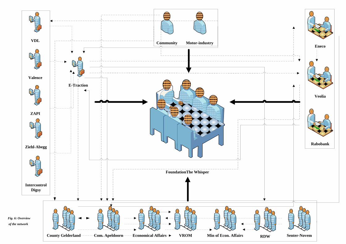
55
FoundationThe Whisper
E-Traction
Economical Affairs
EnecoCommunity Motor-industry
Veolia
Rabobank
ZAPI
VDL
Ziehl-Abegg
Senter-NovemRDWVROMCounty Gelderland Com. Apeldoorn Min of Econ. Affairs
Intercontrol
Digsy
Valence
Fig. 6: Overview
of the network
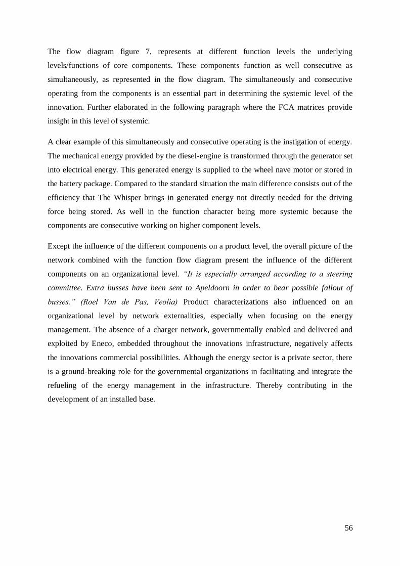
56
The flow diagram figure 7, represents at different function levels the underlying
levels/functions of core components. These components function as well consecutive as
simultaneously, as represented in the flow diagram. The simultaneously and consecutive
operating from the components is an essential part in determining the systemic level of the
innovation. Further elaborated in the following paragraph where the FCA matrices provide
insight in this level of systemic.
A clear example of this simultaneously and consecutive operating is the instigation of energy.
The mechanical energy provided by the diesel-engine is transformed through the generator set
into electrical energy. This generated energy is supplied to the wheel nave motor or stored in
the battery package. Compared to the standard situation the main difference consists out of the
efficiency that The Whisper brings in generated energy not directly needed for the driving
force being stored. As well in the function character being more systemic because the
components are consecutive working on higher component levels.
Except the influence of the different components on a product level, the overall picture of the
network combined with the function flow diagram present the influence of the different
components on an organizational level. “It is especially arranged according to a steering
committee. Extra busses have been sent to Apeldoorn in order to bear possible fallout of
busses.” (Roel Van de Pas, Veolia) Product characterizations also influenced on an
organizational level by network externalities, especially when focusing on the energy
management. The absence of a charger network, governmentally enabled and delivered and
exploited by Eneco, embedded throughout the innovations infrastructure, negatively affects
the innovations commercial possibilities. Although the energy sector is a private sector, there
is a ground-breaking role for the governmental organizations in facilitating and integrate the
refueling of the energy management in the infrastructure. Thereby contributing in the
development of an installed base.
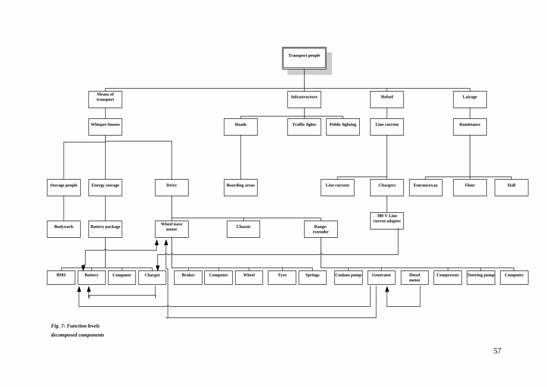
57
Transport people
Whisper-busses
Traffic lights
Public lighting
Roads
Line current
Remittance
Energy storage
Drive
Storage people
Boarding areas
Line current
Chargers
Floor
Hall
Entranceway
Wheel nave
motor
Means of
transport
Infrastructure
Refuel
Lairage
Range-
extender
Battery package
Bodywork
380 V Line
curren adapter
Diesel
motor
Charger
Computer
Computer
BMS
Steering pump
Coolant pump
Compressor
Generator
Chassis
Battery
Wheel
Tyre
Computer
Springs
Brakes
Fig. 7: Function levels
decomposed components
58
6.3 Describing the systemic innovation: identifying interdepencies and
coordinate specifications of new interfaces
The innovations systemic nature manifests itself mainly in the interaction between
components performance of different functions. If several components provide a function
which are also involved in providing other functions, a systemic character is revealed.
6.3.1 Function component matrix: analyzing product characteristics
The network in which the innovation is introduced, implemented and the different function
levels it influences is illustrated by Figure 6 and 7. Figure 8 and figure 9 illustrate the
function-component matrices for the two buses using the allocation procedure. The next step
in determining the FCA is to calculate two indices for each function that shows how each
function differs from the standard modular situation, which is represented by a low one-to-one
relationship with a component.
By analyzing the product characteristics it becomes clear whether the product architecture is
modular or non-modular (integral). “The extent to which a product architecture is modular,
non-modular, is information that is required for each function and attribute individually. How
exactly a function is different from the perfectly modular situation, by the one-to-one
relationship between function and component is important knowledge.”181
The two different indices reflect two possible different divergences in a relationship. The first
index identifies the number of components that jointly provide a function. This index is
calculated for each function in the column known as „Index 1‟. The second index identifies
the extent to which the set of components, used for Index 1 also support other functions. In
order to calculate this index, every component identified in index 1 are viewed and added up
to the number of functions the component is jointly involved in. Counted up into the last
column in the FCA matrix it is known as „Index 2‟. The more functions a component is jointly
involved in leads to a more integral product architecture. Three components in the Whisper
bus contribute in the function „protection‟, therefore Index 1 = 3. Some of the components
contributing in the function protection also contribute to the functions „suspend structure‟,
„drive‟ and „energy conversion‟ (Index 2 = 1 + 3 = 4 for the function „protection‟).
The FCA matrices provide the overview and evidence that the new bus has a strong product
architecture characterization. It is striking that in these two matrices, as seen in by indices 1
181 Fixson (2005), p. 354.
59
and 2, there is more interaction to be seen between functions and components from The
Whisper. The standard bus does not represent a “ideal modular” one-to-one mapping
architecture, in contrary the Whisper is characterized as a more non-modular/integral
architecture. Therefore the FCA matrices evidently show that the interaction between
different modules and therefore the systemic character of the product is stronger represented
within The Whisper opposed to a standard bus. Many of the components that are
characterized as modular are being replaced by non-modular components.
“Many components are not implemented any more. For instance the differential and the
sprocket-wheel are all being removed. Instead of these components others replace them.”
(Roel Van de Pas, Veolia)
Overall the number of components that jointly provide a function (index 1) is even or has
risen. Concerning the functions energy storage (f1), energy conversion (f2) and protection (f6)
the components that jointly provide these function has risen with 1 component. Concerning
index 2, the calculation of index 1 and the number of functions the component is involved in
the same applies as to index 1, the number has risen or stayed even. Concerning the functions
steering and suspend structure are equal as opposed to a standard bus. The functions energy
storage, drive, electrics and protection have risen with 1. Meaning that for all these functions
a component was involved in jointly providing one function more as opposed to the standard
bus. Focusing on the function energy conversion it is striking that the components jointly
responsible for providing the energy conversion are now involved in the performance of three
other functions more, opposed to the standard bus. This results in a stronger integral product
architecture, represented the strongest in a joint performance of energy conversion.
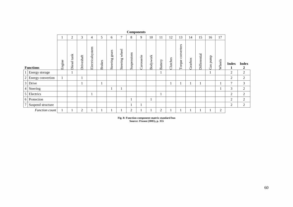
60
Components
1 2 3 4 5 6 7 8 9 10 11 12 13 14 15 16 17
Functions En
gin
e
Die
sel
tan
k
Dri
ves
haf
t
Ele
ctri
cals
yst
em
Bra
kes
Ste
erin
g g
ears
Ste
erin
g w
hee
l
Su
spen
sio
ns
Car
oss
erie
Bo
dy
wo
rk
Bat
tery
Clu
tch
es
To
rque
con
ver
ters
Gea
rbox
Dif
fere
nti
al
Gas
pum
p
Wh
eels
Index
1
Index
2
1 Energy storage 1
1 1 2 2
2 Energy convertion 1 1 2 2
3 Drive 1 1 1 1 1 1 1 7 3
4 Steering 1 1 1 3 2
5 Electrics 1 1 2 2
6 Protection 1 1 2 2
7 Suspend structure 1 1 2 2
Function count 1 1 2 1 1 1 1 2 1 1 2 1 1 1 1 1 2
Fig. 8: Function component matrix standard bus
Source: Fixson (2005), p. 355
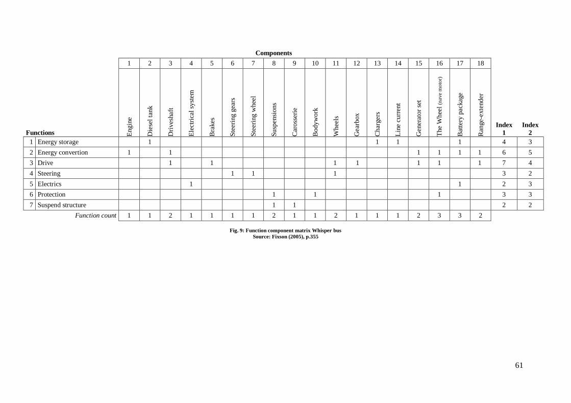
61
Components
1 2 3 4 5 6 7 8 9 10 11 12 13 14 15 16 17 18
Functions En
gin
e
Die
sel
tan
k
Dri
ves
haf
t
Ele
ctri
cal
syst
em
Bra
kes
Ste
erin
g g
ears
Ste
erin
g w
hee
l
Su
spen
sio
ns
Car
oss
erie
Bo
dy
wo
rk
Wh
eels
Gea
rbox
Ch
arger
s
Lin
e cu
rren
t
Gen
erat
or
set
Th
e W
hee
l (n
ave
mo
tor)
Bat
tery
pac
kag
e
Ran
ge-
exte
nd
er
Index
1
Index
2
1 Energy storage 1 1 1 1 4 3
2 Energy convertion 1 1 1 1 1 1 6 5
3 Drive 1 1
1 1 1 1 1 7 4
4 Steering 1 1 1 3 2
5 Electrics 1 1 2 3
6 Protection 1 1 1 3 3
7 Suspend structure 1 1 2 2
Function count 1 1 2 1 1 1 1 2 1 1 2 1 1 1 2 3 3 2
Fig. 9: Function component matrix Whisper bus
Source: Fixson (2005), p.355
62
6.3.2 Product architecture assessment: defining interface characteristics
A products interface characteristics are often described with terms such as „coupled‟ or
„dependent‟. The interfaces‟ roles for the product function, i.e. their types, are determined by
their nature, number and reversibility. The theoretical background of the interface assessment
has been amplified in chapter 5.1. the interface matrices for the two buses are represented in
figure 10.
“We have completely pulled it apart and therefore it now becomes separate parts electrically
linked together. That is the big difference, and furthermore all these systems are integrated.”
(Arjan Heinen, director e-Traction)
Due to their mechanical characteristics, most of the interfaces of both buses are spatial.
Overall the Whisper bus has a higher interaction between interfaces and a higher number of
interfaces in total. The number interfaces (46) expressed as a percentage of the theoretical
maximum number of interfaces (136) shows that there is an increase of over 4%. The standard
bus having a percentage of 33.82% and the Whisper bus 37.9%.
The higher interaction between interfaces applies to three out of four forms considered.182
Only on material interaction, the need for the exchange of materials, both buses score a 0.
Meaning that there is no need for the exchange of materials between interfaces in both buses.
Adjacent to the number of interfaces their characteristics show that the product architecture of
the Whisper bus has a more integral character opposed to the product architecture of a
standard bus. Based on the general quantification scheme presented in fig. 5 the SIEM
demonstrates the systemic character.183
A higher intensity of these interactions demonstrates a
higher integral character. The standard bus has a total Spatial interactions of 74 vs. 84 in the
Whisper bus, hence an increase of 10 is established. This increase also applies to Information
(+24) and Energy (+13).
Note that despite the differences in the FCA schemes, both architectures do still exhibit a
number of similarities with respect to the type of interfaces. The Whisper bus represents a
significant higher score on energy and information. The components who differ from the
standard bus can be considered to have a greater need for energy transfer and a need for
information or signal exchange between two elements.
182 Pimmler and Eppinger (1994).
183 Pimmler and Eppinger (1994).
63
It is clear that the new components such as the wheel nave motor and range extender interacts
with a significant number of other components (relative to the total number of components)
represented in fig. 9 & 11, playing a pivotal role in the product architecture. The wheel nave
motor is a component which signals a central component supplying and generating general
functionality. The Whisper which has many components that show interactions with many
other components, displayed in figure 11, therefore it is more integral.
6.3.3 Product architecture assessment: interface reversibility how deep is the component
„buried‟ in the product
The second interface characteristic analyzed is the interfaces „reversibility‟, amplified in
chapter 5.2.2. interface type irreversibility.
Opposed to the standard bus the number of interfaces of the Whisper are more numerous.
Accounted for by the addition and replacement of several new components added to the
Whisper bus.
The results for the two buses are shown in the lower triangles of the matrices in figure 10.
With respect to the difficulty to reverse, most of the interfaces are similar. This goes as far as
the components consistent in both buses. Characterized by the addition of several components
the reversibility of the Whisper bus is lower opposed to a standard bus. The criteria to assess
effort to disconnect interfaces of the standard bus are considered overall low-medium. Where-
as the product architecture of the Whisper bus, especially considering the additive
components, the criteria to assess effort to disconnect an interface as medium-high. The
systemic character is strengthened, due that “the notion of various product changes over the
product life, such as upgrades, add-ons, adaptation, wear, consumption, or reuse – which are
often assumed as being one of the major advantages of modular product architectures –
strongly depends on the reversibility of the interface.”184
The Whisper exhibits significant „depth‟ composed to the standard bus in which of the
interfaces are „buried‟ within the product. Note, that especially the additional/deviant
components interfaces are „buried‟ in the product. If these components were to be replaced it
would require disconnecting several of the relevant interfaces.
184 Fixson (2005), p.359.
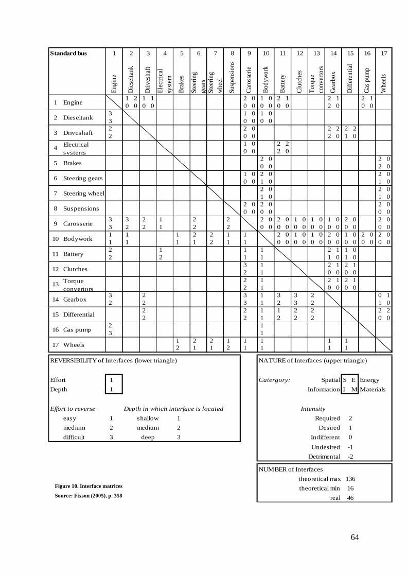
64
Standard bus
1 2 1 1 2 0 1 0 2 1 2 1 2 1
0 0 0 0 0 0 0 0 0 0 2 0 0 0
3 1 0 1 0
3 0 0 0 0
2 2 0 2 2 2 2
2 0 0 2 0 1 0
1 0 2 2
0 0 2 0
2 0 2 0
0 0 2 0
1 0 2 0 2 0
0 0 1 0 1 0
2 0 2 0
1 0 1 0
2 0 2 0 2 0
0 0 0 0 0 0
3 3 2 1 2 2 2 0 2 0 1 0 1 0 1 0 2 0 2 0
3 2 2 1 2 2 0 0 0 0 0 0 0 0 0 0 0 0 0 0
1 1 1 2 2 1 1 2 0 1 0 1 0 2 0 1 0 2 0 2 0
1 1 1 1 2 1 1 0 0 0 0 0 0 0 0 0 0 0 0 0 0
2 1 1 1 2 1 1 0
2 2 1 1 1 0 1 0
3 1 2 1 2 1
2 1 0 0 0 0
2 1 2 1 2 1
2 1 0 0 0 0
3 2 3 1 3 3 2 0 1
2 2 3 1 2 3 2 1 0
2 2 1 1 2 2 2 2
2 2 1 2 2 2 0 0
2 1
3 1
1 2 2 1 1 1 1 1
2 1 1 2 1 1 1 1
REVERSIBILITY of Interfaces (lower triangle) NATURE of Interfaces (upper triangle)
Effort 1 Catergory: S E Energy
Depth 1 I M Materials
Effort to reverse Depth in which interface is located
easy 1 1
medium 2 2
difficult 3 3
NUMBER of Interfaces
136
16
46
theoretical max
theoretical min
real
-2
shallow
medium
deep
Spatial
Information
Detrimental
Undesired
Indifferent
Desired
Required
Intensity
2
1
0
-1
Battery
Wheels
13
14
15
16
17
Clutches
Torque
convertors
Gearbox
Differential
Gas pump
12
Electrical
systems4
Brakes5
Steering gears6
7
8
9
10
11
Steering wheel
Suspensions
Carosserie
Bodywork
Engine1
Dieseltank2
Driveshaft3
176 7 8 9 10 11 12 13 14 15 16
To
rqu
e
con
ver
tors
Gea
rbo
x
Dif
fere
nti
al
Gas
pu
mp
Wh
eels
1 2 3 4 5
Clu
tch
es
En
gin
e
Die
selt
ank
Dri
ves
haf
t
Ele
ctri
cal
syst
em
Bra
kes
Ste
erin
g
gea
rs
Ste
erin
g
wh
eel
Su
spen
sio
ns
Car
oss
erie
Bo
dy
wo
rk
Bat
tery
Figure 10. Interface matrices
Source: Fixson (2005), p. 358
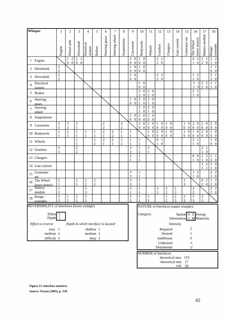
65
1 2 1 1 2 0 1 0 2 1 0 2 1 1 2 2
0 0 0 0 0 0 0 0 2 0 1 0 2 0 1 0
3 1 0 1 0 1 1
3 0 0 0 0 0 0
2 2 0 2 2 1 2 2 1
2 0 0 2 0 1 0 2 0
1 0 1 1 2 2 1 1
0 0 1 0 2 0 1 0
2 0 2 0 2 1
2 0 2 0 1 0
1 0 2 0 2 0
0 0 1 0 1 0
2 0 2 0
1 0 1 0
2 0 2 0 2 0
0 0 0 0 0 0
3 3 2 2 2 2 0 2 0 1 0 1 0 1 0 2 0 2 0 2 0
3 2 1 2 2 0 0 0 0 0 0 0 0 0 0 0 0 0 0 0 0
1 1 1 1 1 2 2 1 1 1 0 2 0 1 0 1 0 1 0 2 0 1 0
1 1 1 1 1 1 2 1 1 0 0 0 0 0 0 0 0 0 0 0 0 0 0
1 1 2 2 1 1 1 0 1 2 1 1 0
1 2 1 1 2 1 1 1 0 1 0 0 0
3 2 3 1 2 2 1
3 2 3 2 1 1 0
2 1 0 0 2 2 2 1
1 1 1 0 1 0 2 0
1 2 1 0
1 1 1 0
3 1 1 2 2 2
3 1 1 0 2 0
2 2 2 2 3 1 2 0 2 1 2
1 1 2 2 3 1 3 2 0 2 0
1 3 3 1 3 2 2 2 2 2
2 3 1 1 3 2 3 2 2 0
3 1 2 3 3 1 1 1 2 2 3 3
3 1 1 2 3 1 1 2 3 3 3 3
REVERSIBILITY of Interfaces (lower traingle)
1 Category: Spatial S E Energy1 Information I M Materials
Depth in which interface is located Intensity
1 shallow 1 Required
2 medium 2 Desired
3 deep 3 Indifferent
Undesired
Detrimental
EffortDepth
Effort to reverse
easy
medium
difficult
8 9
Die
sel
tan
k
Dri
ves
haf
t
2 3 4 5 6 7
17
153
58
-1
-2
2
Whisper
theoretical minreal
10 11 1312
Gea
rbo
x
14
NATURE of Interfaces (upper triangle):
6
Chargers
Range-
extender
18
theoretical max
NUMBER of Interfaces
15 16 171
Engine
9
Dieseltank
Driveshaft
Electrical
system
Brakes
Steering
gears
3
4
5
Th
e W
hee
l
(nav
e m
oto
r)
7
8S
teer
ing
wh
eel
Ch
arg
ers
Su
spen
sio
ns
Car
oss
erie
Bo
dy
wo
rk
Steering
wheel
En
gin
e
Bodywork
1
Bra
kes
Bat
tery
mo
du
le
Ran
ge-
exte
nd
er
Battery
module
Wheels
Wh
eels
Lin
e cu
rren
t
Gen
erat
or
set
Generator
set
Ste
erin
g g
ears
10
11
13
14
15
Ele
ctri
cal
syst
em
Suspensions
Carosserie
The Wheel
(nave motor)
2
1
0
16
17
18
Gearbox12
Line current
Figure 11. Interface matrices
Source: Fixson (2005), p. 358
66
6.3.4 Introduction of the innovation: breaking through the excess inertia by compatible
interfaces
As identified the degree of systemic characterization does not show a difference in the general
interaction quantification regarding all components, especially concerning the components
present in both buses. Nevertheless, there is a great influence exercised on the interfaces and
organizations involved. Table 1 provides the liaison between the technology (the interface)
and the organizational design decisions.
“The busses whom we charge are connected with a standard 380w cable coupler. This is
applicable with the current infrastructure. Waiting until the electrical charging stations are
implemented is no option, without electrical cars there are no charging stations and vice
versa” (Arjan Heinen, director e-Traction)
The leading invention inside the innovation is The Wheel nave motor. By implementing The
Wheel nave motor e-Traction will have to develop the soft- and hardware and share their
knowledge. The sharing of knowledge is done by training customer mechanics. Sharing the
knowledge creates a greater understanding of the invention and will instigate a greater
supporting ground.
Next to the innovation itself it has to prove itself, there are several boundary conditions that
need to be supportive. When commencing the buses into the traffic and implement them in the
organizations fleet it is necessary that they are insurable and allowed on the public road. In
which there is an important role for the governmental decision makers in order to make it
possible.
“There is a huge risk independent from the technology itself. The biggest risk lies with the
technology, but when you look at the complexity surrounding the start-up of such a project.
Starting with the fact that you do not get a liability insurance.” Van der Ven, (Director,
Whisper Foundation)
The influence of network externalities manifests itself most clearly in the energy
management. A vehicle dependent on electrical energy needs a charging station within reach.
Hence it concerns a city bus, therefore a charging station in the car barn is sufficient.
Although when the technique is broadly grounded it is important that it has a broader
coverage. Eneco developed a charging station delivering energy to the electrical driven
vehicles. E-Traction already made the interface of the bus compatible with the industry
67
standard, therefore Eneco needs to provide a network of charging stations (installed base).
Compatible general governments interest in a durable automotive solution.
“It will work with the current infrastructure. That is our basic assumption. For if we have to
wait for charging stations to be placed everywhere, it is the classical chicken-egg story. There
is no charging station, therefore you still have no electric cars and due to the absence of
electrical cars there is no interest in placing charging stations, we’re not going to wait on it.
(Arjan Heinen , director e-Traction)
As displayed in table 1, the several added components have an impact both within the product
and its interface as on the organizations involved in the Whisper project. The influence and
characterization of network externalities reveals itself in how to cope with the products energy
demand.
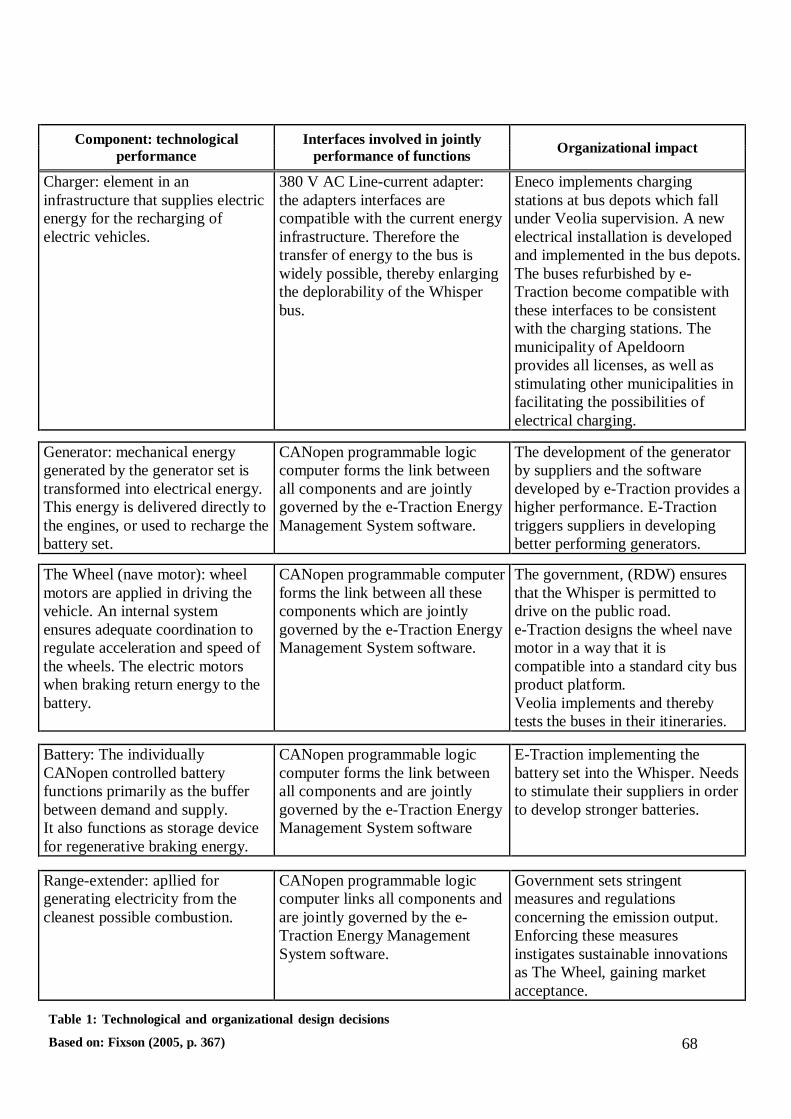
68
Component: technological
performance
Interfaces involved in jointly
performance of functions Organizational impact
Charger: element in an
infrastructure that supplies electric
energy for the recharging of
electric vehicles.
380 V AC Line-current adapter:
the adapters interfaces are
compatible with the current energy
infrastructure. Therefore the
transfer of energy to the bus is
widely possible, thereby enlarging
the deplorability of the Whisper
bus.
Eneco implements charging
stations at bus depots which fall
under Veolia supervision. A new
electrical installation is developed
and implemented in the bus depots.
The buses refurbished by e-
Traction become compatible with
these interfaces to be consistent
with the charging stations. The
municipality of Apeldoorn
provides all licenses, as well as
stimulating other municipalities in
facilitating the possibilities of
electrical charging.
Generator: mechanical energy
generated by the generator set is
transformed into electrical energy.
This energy is delivered directly to
the engines, or used to recharge the
battery set.
CANopen programmable logic
computer forms the link between
all components and are jointly
governed by the e-Traction Energy
Management System software.
The development of the generator
by suppliers and the software
developed by e-Traction provides a
higher performance. E-Traction
triggers suppliers in developing
better performing generators.
The Wheel (nave motor): wheel
motors are applied in driving the
vehicle. An internal system
ensures adequate coordination to
regulate acceleration and speed of
the wheels. The electric motors
when braking return energy to the
battery.
CANopen programmable computer
forms the link between all these
components which are jointly
governed by the e-Traction Energy
Management System software.
The government, (RDW) ensures
that the Whisper is permitted to
drive on the public road.
e-Traction designs the wheel nave
motor in a way that it is
compatible into a standard city bus
product platform.
Veolia implements and thereby
tests the buses in their itineraries.
Battery: The individually
CANopen controlled battery
functions primarily as the buffer
between demand and supply.
It also functions as storage device
for regenerative braking energy.
CANopen programmable logic
computer forms the link between
all components and are jointly
governed by the e-Traction Energy
Management System software
E-Traction implementing the
battery set into the Whisper. Needs
to stimulate their suppliers in order
to develop stronger batteries.
Range-extender: apllied for
generating electricity from the
cleanest possible combustion.
CANopen programmable logic
computer links all components and
are jointly governed by the e-
Traction Energy Management
System software.
Government sets stringent
measures and regulations
concerning the emission output.
Enforcing these measures
instigates sustainable innovations
as The Wheel, gaining market
acceptance.
Table 1: Technological and organizational design decisions
Based on: Fixson (2005, p. 367)
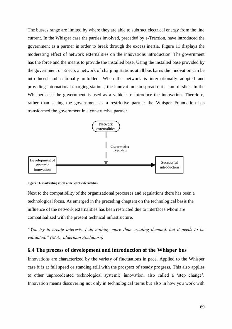
69
The busses range are limited by where they are able to subtract electrical energy from the line
current. In the Whisper case the parties involved, preceded by e-Traction, have introduced the
government as a partner in order to break through the excess inertia. Figure 11 displays the
moderating effect of network externalities on the innovations introduction. The government
has the force and the means to provide the installed base. Using the installed base provided by
the government or Eneco, a network of charging stations at all bus barns the innovation can be
introduced and nationally unfolded. When the network is internationally adopted and
providing international charging stations, the innovation can spread out as an oil slick. In the
Whisper case the government is used as a vehicle to introduce the innovation. Therefore,
rather than seeing the government as a restrictive partner the Whisper Foundation has
transformed the government in a constructive partner.
Development of
systemic
innovation
Successful
introduction
Network
externalities
Characterizing
the product
Figure 11. moderating effect of network externalities
Next to the compatibility of the organizational processes and regulations there has been a
technological focus. As emerged in the preceding chapters on the technological basis the
influence of the network externalities has been restricted due to interfaces whom are
compatibalized with the present technical infrastructure.
“You try to create interests. I do nothing more than creating demand, but it needs to be
validated.” (Metz, alderman Apeldoorn)
6.4 The process of development and introduction of the Whisper bus
Innovations are characterized by the variety of fluctuations in pace. Applied to the Whisper
case it is at full speed or standing still with the prospect of steady progress. This also applies
to other unprecedented technological systemic innovation, also called a „step change‟.
Innovation means discovering not only in technological terms but also in how you work with
70
other parties trying to pursue combined goals. Therefore, the Whisper already remarkable, is
an example of a public-private partnership.
“As the municipality of Apeldoorn there are being set up investment programs in order to
stimulate electrical transportation.” (Cevaal Douma, project concultant municipality
Apeldoorn)
Innovations in electric transport are at the order of the day, overwhelmed with publicity. After
a long development phase a very complex innovative product The Wheel, with a huge
potential application in practice on his merits, is introduced. With the public transport
passenger market, it had a rock-hard critical jury, as the ultimate test.
The innovation thrives on the invention of The Wheel, a wheel nave driven motor. The Wheel
as a laboratory-type invention utilized in The Whisper and further developed in conjunction
with other components. Decisive is collaboration with various parties, both at government
level and the corporate market. Within the supply chain there is intense horizontal
(stakeholders) and vertical (suppliers, customers) cooperation, all coordinated within the
Whisper Foundation.
“In coordinating such a project you need a strong coordinator. Mostly an external consultant
is asked for the job. Whom coordinates the project and make sure that all the administrative
tasks and the like.” (Dubbeld, department of Economical Affairs)
Knowledge about the applicability and usability of the product is accumulated through
product knowledge i.e. through training customer technicians. By sharing knowledge, one
hopes to receive more knowledge in the products applicability and how the innovation reacts
to different conditions. Thereby providing information of inestimable value on the product
and its abilities.
“We are not afraid to share knowledge. Currently people are trained from Korea and Sweden
on how to built a bus using our invention.” (Arjan Heinen, director e-Traction)
In the product introduction there is deliberately chosen to approach the government. The main
reason for approaching the government are the absence of direct commercial interests. In
addition, they are committed to projects with a long lead time, usually the case with
(systemic) innovations like The Whisper.
71
“The main reason for choosing busses is to create visibility and the government has great
interests.” (Arjan Heinen, director e-Traction)
Three striking examples from the field of practice on how the collaboration was between the
participating parties and their involvement are:
1. The engineering of a innovation such the Whisper is relatively time-consuming. It is
due to a truly exceptional step of the municipality of Apeldoorn that prematurely
engineering was able. The municipality provided funding, while the overall project in
central authorities was still awaiting approval. Such decisiveness is extremely peculiar
in the bureaucratic Netherlands.
2. As a public transportation company Veolia is backing up the project fully, but what
would there incentives be? Veolia earns their businesses by providing the best tender
at license grants. In recent years the Dutch public transportation companies have been
squeezed greatly by the licensing authorities, which brought fierce competition,
thereby leaving little room for research and development. Participating in innovative
projects as such are to a carrier additional costs incurred by irregularity, additional
losses due to fallout ratio and higher inefficiency. Nevertheless Veolia is highly
motivated along with project The Whisper, inspired by the philosophy that Veolia on
the long term, as the world his largest public transport company, can only be
successful if they remain to provide safe and sustainable mobility solutions. Therefore
the Whisper project is closely monitored.
3. As a corollary to the business partners the government has played a huge role in the
project. The ministry of infrastructure and environment and the county Gelderland.
The Whisper Foundation received a contribution of both and without the size of the
amount provided the foundation would not even have been founded. The government
policy has stimulated and worked.
The integral character of the component The Wheel in the implementation of the bus requires
changes in other parts of the product as well on other organizations. The wheel nave motor
requires a technological investment of suppliers and participants in the network. In order to
storage and supply the energy a battery package adjacent to the requirements is developed by
suppliers. The innovation also requires a dataflow within the system, therefore a electronic
system is essential, developed and implemented in the innovation.

72
The energy requirement of the vehicle characterizes the network externality impact. A
network of junctions for charging the buses. Without these charging stations the bus is not
able to be implemented in a timetable. In order to implement the innovation in the general
city-bus market a network of charging stations is required. The lack of a network of charging
stations (installed base) is the shortfall in order to break through the excess inertia.
Next to the technological investment the systemic innovation requires adaptations in general
regulation to implement the innovation in the timetable of Veolia.
73
7. Summarizing and linking the findings: laboratory-type
innovation process with limited partner involvement as a
challenge
It is clear that the Whisper is a textbook example of a public private partnership. Not without
reason, this issue is forwarded separately. In general the public has no idea what
organizational, technical, financial, transport technical approvals, insurance and other
obstacles must be overcome in order to commencing a single bus. Only due to the fact that a
group of partners – from completely different backgrounds and manifold incentives- had the
consent to put in their best efforts in order to let the project succeed.
A central element in determining the systemic character of the innovation is the product
architecture concept, represented by the FCA method.185
By focusing on the number of
interfaces and the interactions between interfaces the degree of the systemic character is
determined. Applying the model proved to be a practicable method in determining the
systemic (integral) character and the degree of modularity. The existing theory is almost
complete but a gap still exists in the organizational consequences the linking of interfaces
practices. Hereby exposing the influence that network externalities practise on both the
product characteristics and the organization(s).
The theoretical method has been applied by decomposing an innovation into its components
and the functions performed by these components. By identifying and classifying the product
his interface characteristics the (integral) systemic character of the innovation became clear.
Applying the model to the Whisper case it became clear that the integrality of the innovation
is high, for it has strong interfaces and a low reversibility. Resulting in a strong difference
between a modular innovation or an integral and systemic innovation. The product
architecture of the Whisper is characterized by a systemic and integral product architecture.
Because it is integrated and buried deep in the product his architecture it resembles strong
systemic characteristics. The side-effects of network externalities are minimized by adapting
the interfaces to the current infrastructure. In order to evolve the innovation and implement it
on a larger scale it is inevitable to adjust the infrastructure and break through the excess
inertia by creating a greater installed base.
185 Fixson (2005); Pimmler and Eppinger (1994).
74
7.1 Theoretical implications: For model development and knowledge gained
on systemic innovations characterized by network externalities
Radical innovations which change core technical concepts and their linkages lead to adaptive
challenges for organizations.186
Therefore, there is an increased number of papers about the
impact of radical innovations on product architecture187
and recognizing the influence of
systemic innovations.188
Focusing on systemic innovation in relation to product design,
supplier management, information technology. One of the first scholars to provide insights in
how to break through the excess inertia are Dew and Read.189
Still a literature gap exists on
how to introduce a systemic innovation characterized by network externalities.
In this study a conceptual model is tested in order to expand the existing literature by focusing
on the introduction this type of innovation. Thereby the study contributes to the systemic
innovation literature twofold. First by analyzing the influence of network externalities on the
introduction of a systemic innovation and secondly introducing the entity of a foundation in
order to coordinate a PPP cooperation. In managing a PPP cooperation a foundation serves as
an outstanding equity based alliance form. Partner commitment rises and the governmental
participants are able to offer grants without the apparent conflict of interest.
Since innovations are not all ready to copy one-on-one, not all introductions of (systemic)
innovations should be managed similarly, especially when characterized by network
externalities. When introducing a network externality product it is inevitable to either invest
the installed base or enhance the product value.190
This study suggests that breaking through the excess inertia the government forms an
exceptionally good partner. The findings implicated that in order to break through the excess
inertia induced by network externalities it is possible to weaken the effects by adjusting
interfaces to the existing infrastructure.191
The findings also suggests that when cooperating
with a governmental organization it is necessary to establish an independent entity. An
independent entity works as a mediating factor between the parties involved and facilitates
that all parties involved are able to focus on their core business.
186 Tushman and Anderson (1986). 187
Pimmler and Eppinger (1994); Fixson (2005). 188 Henderson and Clark (1990); Linkvist et al. (1998); as well as Magnusson et al. (2002). 189 Dew and Read (2007). 190 Dew and Read (2005). 191 Dew and Read (2007).
75
7.2 Managerial implications: a general, private cooperation vital for the
introduction
Based on the study its findings, several managerial recommendations are developed. First of
all, the research findings suggest that in order to introduce a systemic innovation-
characterized by network externalities- an installed base or product value is essential. Coping
with the introduction of a case with similar characteristics as the Whisper case, an installed
base is essential. At the same time, the product value met sufficient conditions and at the same
not appropriate due to the lack of possibilities by the inventing firm to enter into mass-
production.
The implication is that firms should engage in a PPP when the introduction of their product
has a long lead time before it is fully applicable in the market and meets customer demands.
Due to the fact that a government serves public interests instead of commercial. Thereby
implicating that a governmental partner is reliable in creating the installed base necessary to
break through the excess inertia. Next to the conditions in order to launch the innovation, a
government cannot provide subsidiaries directly to organizations, an independent entity where
both parties are represented in the form of a foundation serves as an outcome.
Moreover the findings suggest that the coordination of the product through a foundation is an
effective vehicle when introducing a systemic innovation. The coordinating and moderating
effect of a foundation, that contributes in creating deeper understanding and the influencing of
decisions across product domains, such as organizational and regulatory process.
Complemented with a high social standing provide a broad support in order to market the
product.
7.4 Future research and limitations
While the product architecture framework produces a promising result on innovation
influenced by network externalities the research field finds itself in an early stage. Endorsed
by a general market becoming more influenced by network externalities it provides a perfect
ground for research focusing on small ventures launching systemic innovative products or
services. The governmental role has been restricted to a regional and more or less national
role, therefore future research could involve more focus on national or international
governmental cooperation.
76
This research has focused on the collaboration between government and the private sector.
Hopefully this study will assist in the introduction of a systemic innovation characterized by
network externalities. Moreover that the research will trigger scholars in future examining the
introduction of equivalent innovations characterized by network externalities.
Limitations
Despite the care taken at the different stages of this study, there are still several limitations
that need to be taken into account by interpreting the findings. First, by choosing to focus on
The Whisper- an innovation introduced in the automotive industry, there is a danger to
generalize the study its findings to other industries. Future research is necessary in order to
generalize the findings in a brother perspective.
The second limitation concerns governmental cooperation. The governmental influence and
national legislation provided will not be identical in every municipality, county or on a higher
level country. Therefore it is important when selecting the case that these factors are taken
into account and especially the grant provided could influence the objectivity.
Thirdly, the research had to deal with the time-frame in which the research is done. In the case
study of The Whisper it concerns an introduction, but the project is not finished. Although
aware that the timeframe (2010) may be too short to call the case a definite success all
indications give a positive implication. Therefore future researchers are suggested to select a
case which is completed.
Final limitation is that the organization that founded the core element of the innovation are not
able to mass-produce the innovation. As a result the research could not asses how the market
and organizations respond, had the innovation be commercialized on a larger scale.
Despite these limitations, the research has provided interesting insight in the introduction of a
systemic innovation characterized by network externalities. Hopefully this study will provide
managers and parties concerned new insights and a method in order to introduce similar
innovations. As well as other scholars inspiration to conduct a follow-up research in order to
gain more insight in systemic innovation.

77
Guidance for this research has been provided by Twente University, E. Hofman & H. Schiele.
Appreciated is the assistance of E-Traction, foundation The Whisper, Eneco, Community of Apeldoorn and The Department of Economical Affairs for their cooperation to execute this research.
78
References
e-Traction. “Direct-drive electric propulsion: a cost effective ay to conserve energy and
reduce pollution.” e-Traction_briefing_11-07-07. Apeldoorn, 07 07 11.
Free patents online all the inventions of mankind. (2010). Retrieved 7, 7, 2010, from Free
patents online: http://www.freepatentsonline.com/7059437.html
The Whisper zuinig, schoon en stil. http://www.thewhisper.nl/Pages/Default.aspx (accessed
may 12, 2010).
Inform-Active Multimedia (2010). Retrieve 3, 9, 2010, from Inform-Active Multimedia:
http://www.inform-active.com.au/flash_car.htm
Ahuja, G. “Collaboration networks, structural holes and innovation: A longitudinal study.”
Administrative Science Quarterly 45, no. 3 (2000): 425-456.
Annique Un, C, Alvarro Cuervo-Cazurra, and Kazuhiro Asakawa. “R&D Collaborations and
Product Innovation.” Product Development & Management Association, 2010: 673-689.
Assine, A, D Falkenburg, and K Chelst. “Engineering design management: an information
structure approach.” International Journal of Product Research, 1999: 2957-2975.
Baldwin, C.Y., and K.B. Clark. “Managing in an Age of Modularity.” Harvard Business
Review, 75, 84-93 75 (1997): 84-93.
Bayona, C., T. Garcia-Marco, and E. Huerta. “Firms' motivations for co-operative R&D: an
empirical analysis of Spanish firms.” Research Policy, no. 30 (2001): 1289-1307.
Bower, Joseph L., en Clayton M. Christensen. „Disruptive Technologies: Catching the
Wave.” Harvard Business Review (Harvard Business School Publishing), January-February
1995: 43-53.
Brusoni, S., A. Prencipe, and K. Pavitt. “Knowledge specialization, organizational coupling,
and the boundaries of the firm: why do firms know more than they make?” Administrative
Science Quarterly 46 (2001): 597-621.
Brusoni, S., and A. Prencipe. “Technologies, Product, Organisations: opening the task box of
modularity.” Industrial and Corporate Change 10, no. 1 (2001b): 179-205.
79
Brusoni, Stefano, and Andrea Prencipe. “Managing knowledge in loosely coupled networks:
exploring the links between product and knowledge dynamics.” Journal of Management
Studies (Blackwell Publishers) 38, no. 7 (November 2001): 1019-1035.
Brynjolfsson, E., and C.F. Kemerer. “Network externalities in micro-computer software: an
econometric analysis of the spreadsheat market.” Management Science 42, no. 12 (1996):
1627-1647.
Chesbrough, Henry W., and David J. Teece. “Organizing for Innovation: When Is Virtual
Virtuous?” The Innovative Enterprise (Best of HBR), August 1996: 127-135.
Christensen, C. M., and J. L. Bower. “Customer power, strategic investment, and the failure
of leading firms.” Strategic Management Journal 17, no. 3 (1996): 197-218.
Christensen, C.M. “The innovator's dilemma: when new technologies cause great firms to
fail.” Harvard Business School Press., 1997.
Christensen, C.M. “The innovator's solution: Creating and sustaining succesful growth.”
Research technology management 46, no. 5 (2003): 61-61.
Christensen, Clayton M. “Exploring the limits of the technology s-curve.” Production and
Operations Management Society, 1992: 334-357.
Christensen, Verlinden, and Westerman. “Disruption, disintegration and the dissipat ion of
differentiability.” Industrial and Corporate Change 19, no. 5 (2002): 1493-1514.
Cleland, David, and William R King. “Systems analysis and project management.” By David
Cleland and William R King, 307. New York: MC GRAW-HILL, 1968.
Das, S.K., P. Yedlarajiah, and R. Narendra. “An approach for estimating the end-of-life
product disassembly effort and cost.” International Journal of Production Research 38, no. 3
(2000): 657-673.
de Brentani, Ulrike. “Innovative versus incremental new business services: Different keys for
achieving success.” The Journal of Product Innovation Management, no. 18 (2001): 169-187.
De Laat, B. “Systemic innovation and the virtues of going virtual: The case of the digital
video disc.” Technology Analysis & Strategic Management 11, no. 2 (1999): 159-180.
80
Dew, Nicholas, en Stuart Read. „The more we get together: Coordinating network externality
product introduction in the RFID industry.” Elsevier (Technovation), nr. 27 (2007): 569-581.
Dyer, J, and H Singh. “The relational view: Cooperative strategy and source of
interorganizational competitive advantage.” Academy of Management Review 23, no. 4
(1998): 660-679.
Emans, B. Interviewen: theorie, techniek en training. Groningen : Stenfert Kroese, 2002.
Farrell, J., and G. Saloner. “Standardization, Compatibility and innovation.” The Rand
Journal of Economics 16, no. 1 (1985): 70-83.
Fixson, Sebastian K. “Product architecture assessment: a tool to link product, process and
supply chain design decisions.” Journal of Operations Management (Elsevier), no. 26 (2005):
345-369.
Fixson, Sebastian K., and Jin-Kyu Park. “The power of integrality: Linkages between product
architecture, innovation, and industry structure.” Research Policy, 2008: 1296-1326.
Forell, Joseph, en Garth Solaner. „Competition, Compatibility and Standards: The Economics
of Horses, Penguins and Lemmings.” Department of Economics, 09 1986: 1-27.
Foss, N.J. “Leadership, beliefs and coordination: an explorative discussion.” 10, no. 2 (2001):
357-388.
Galbraith, J. “Organization design.” Reading, MA: Addison-Wesley.
Gandal, N., S. Greestein, and D. Salant. “Adoptions and orphans in the early computer
market.” The Journal of Industrial Economic, 1999: 87-106.
Garcia, Rosanna, and Roger Calantone. “A critical look at technological innovation typology
and innovativeness terminology: a literature review.” The Journal of Product Innovation
Management, 2002: 110-132.
Garcia-Canal, E, C Duarte, J Criado, and A Llaneza. “Accelerating international expansion
through global alliances.” Journal of World Business 37, no. 2 (2002): 91-107.
Gilbert, Richard J. „Symposium on Compatibility: Incentives and Market Structure.” The
Journal of Industrial Economics (Blackwell Publishing) 40, nr. 1 (Mar. 1992): 1-8.
81
Gulati, R., P.R. Lawrence, and P. Puranam. “Adaptation in Vertical Relationships: Beyond
incentive conflict.” Strategic Management Journal 26 (2005): 415-440.
Gulati, R.K., and S.D. Eppinger. “The coupling of product architecture and organizational
structure decisions.” Working Paper (MIT Sloan School of Management), 1996: 31.
Hamel, G. “Competition for Competence and Inter-Partner Learning within International
Strategic Alliances.” Strategic Management Journal 12, no. 4 (1991): 83-103.
Hang, C. C., K. B. Neo, and K. H. Chai. “Discontinuous Technological Innovations: A
Review of Its Categorization.” 2006 IEE International Conference. Management of
Innovation and Technology, 2006. 253-257.
Henderson, Rebecca M., en Kim B. Clark. „Architectural Innovation: The Reconfiguration of
Existing Product Technologies and the Failure of Established Firms.” Administrative Science
Quarterly (Johnson Graduate School of Management, Cornell University) 35, nr. 1 (Mar.
1990): 9-30.
Hitt, M.A., R.E. Hoskission, and H. Kim. “International Diversification: Effects on
Innovation and Firm Performance in Product-Diversified Firms.” The Academy of
Management Journal 40, no. 4 (1997): 767-798.
Hobday, M., A. Davies, and A Prencipe. “Systems integration: a core capability of the
modern corporation.” Industrial and Corporate Change 14, no. 6 (2005): 1109-1143.
Hoetker, G. “How much you know versus how well I know you: Selecting a supplier for a
technically innovative component.” Strategic Management Journal 26, no. 1 (2005): 75-96.
Jorde, Thomas M., and David J. Teece. “Innovation and Cooperation: Implications for
Competition and Antitrust.” The Journal of Economic Perspectives (American Economic
Association) 4, no. 3 (Summer 1990): 75-96.
Kale, P, H Singh, and J Bell. “Relating well: Building capabilities for sustaining alliance
networks.” Pearson Press, 2009.
Katz, Michael L., en Carl Shapiro. „Network Externalities, Competition and Compatibility.”
The American Economic Review, June 1985: 424-440.
82
Katz, Michael L., en Carl Shapiro. „Product Introduction with Network Externalities.” The
Journal of Industrial Economics (Blackwell Publishing) 40, nr. 1 (Mar. 1992): 55-83.
Kent, David H. “Joint Ventures vs. Non-Joint Ventures: An Empirical Investigation.”
Strategic Management Journal, no. 5 (12): 387-393.
Kogut, B. “Joint ventures and the option to expand and acquire.” Management Science 37, no.
1 (1991): 19-34.
Kusiak, A. Engineering Design: Products, Processes, and Systems. 1-427: Academic Press,
Inc., 1999.
Langlois, Richard N., en Paul L. Robertson. „Explaining Vertical Integration: Lessons from
the American Automobile Industry.” Journal of Economic History (The Tasks of Economic
History) 49, nr. 2 (Jun. 1989): 361-375.
Langlois, Richard N., en Paul L. Robertson. „Networks and innovation in a modular system:
Lessons from the microcomputer and stereo component industries.” Research Policy (Elevie
Science Publishers B.V.), nr. 21 (1992): 297-313.
Lawrence, Paul R, and Jay W Lorsch. “Differentiation and Integration in Complex
Organizations.” Administrative Science Quarterly, 1967: 1-47.
Leifer, R.R. “The Radical Innovation Imperative.” In Radical innovation: how mature
companies can outsmart upstarts, by Richard Leifer, MCDERMOTT M. Christopher, Gina
Colarelli O'Connor, Lois S Peters, Mark Rice and Robert W. Veryzer, 5. Harvard Business
School Press, 2000.
Li, J., and D.C. Hambrick. “Factional groups: A new vantage on demographic faultlines,
conflict, and disintegration in work teams.” Academy of Management Journal, 48, no. 5
(2005): 794-813.
Lindkvist, L., J. Söderlund, and F. Tell. “Managing product development projects: On the
significance of fountains and deadlines.” Organization Studies 19, no. 6 (1998): 931-951.
MacCormack, A., R. Verganti, and M. Iansiti. “Developing products on "internet time": The
anatomy of a flexible development process.” Management science 47, no. 1 (2001): 133-150.
83
Madhok, A. “Releasing the fundamentals and beyond: Ronad Coase, the transaction cost and
resource-based theories of the firm and the institutional structure of production.” Strategic
Management Journal, 2002: 535-550.
Magnusson, Thomas, Göran Lindström, and Christian Berggren. “Architectural or modular
innovation? Managing discontinuous product development in response to challenging
environmental performance targets.” International Journal of Innovation Management 7, no.
1 (March 2003): 1-26.
Maula, Markku V.J., Thomas Keil, and Jukka-Pekka Salmenkaita. “Open innovation in
systemic innovation contexts to appear in.” In Open Innovation: Researching a New
Paradigm, by Markku V. J. Maula, Thomas Keil and Jukka-Pekka Salmenkaita, 1-36. 2005.
Mclellan, E., K.M. MacQueen, en J.L. Neidig. „Beyond the Qualitative Interview: Data
Preperation and Transcription.” Field Methods, 2003: 63-84.
Miller, R., M. Hobday, T. Leroux - Demers, and X. Olleros. “Innovation in complex systems
industries: the case of flight simulation.” Industrial and corporate change 4, no. 2 (1995):
363-400.
Nieto, M.J., and L. Santamaría. “The importance of diverse collaborative networks for the
novelty of product innovation.” Technovation (Elsevier Ltd.), no. 27 (2007): 367-377.
Pimmler, Thomas U., and Steven D. Eppinger. “Integration analysis of product
decompositions.” ASME Design Theory and Methodology Conference. Minneapolis:
Massachusetts Institute of Technology, 1994. 1-10.
Pisano, G. P. “The governance of innovation: vertical integration and collaborative
arrangements in the biotechnology industry.” Research Policy, 1991: 237-249.
Robertson, P.L., and R.N. Langlois. “Innovation, networks, and vertical integration.”
Research Policy 24, no. 4 (1995): 43-562.
Rohlfs, Jeffrey. “A Theory of Interdependent Demand for a Communications Service.” The
Bell Journal of Economics and Management Science (The RAND Corporation) 5, no. 1
(Spring 1974): 16-37.
Rothaemel, F, and W Boeker. “Old technology meets new technology: Complementaries,
similarities and alliance formation.” Strategic management journal 29, no. 1 (2008): 47-77.
84
Sanchez, R., and J.T. Mahoney. “Modularity, flexibility, and knowledge management in
product and organization design.” Strategic Management Journal, no. 17 (1996): 63-76.
Saunders, Mark, Philip Lewis, and Adrian Thornhill. Research methods for business students.
5. Harlow: Pearson Educational Limited, 2009.
Schiling, M., and H. Steensma. “Disentangling the theories of the firm boundaries: A path
model and empirical test.” Organizational Science 13, no. 4 (2002): 387-401.
Schiling, Melissa A. „Toward a General Modular Systems Theory and Its Application to
Interfirm Product Modularity.” The Academy of Management Review (The Academy of
Management Review) 25, nr. 2 (April 2000): 312-334.
Schreiner, M, P Kale, and D Corsten. “What really is alliance management capability and
how does it impact alliance outcomes and success?” Strategic Management Journal, 2009.
Shan, W. “Environmental risks and joint venture sharing arrangements.” Journal of
International Business Studies, 1991: 555-578.
Shapiro, Carl, en Katz L. Michael. „Systems Competition and Network Effects.” The Journal
of Economic Perspectives (American Economic Association) 8, nr. 2 (Spring 1994): 93-115.
Spinner, M. “Improving project management skill and techniques.” 1989.
Srinivasan, R., G. Lilien, and A. Rangaswamy. “First in, first out? The effect of network
externalities on pioneer survival.” Journal of Marketing 68, no. 1 (2004): 41-58.
Steward, A D. “The design structure system: a method for managing the design of complex
systems.” IEEE Transaction on Software Engineering, 1981: 71-74.
Swann, P.G.M. The economics of standardization. Final Report For Standards and Technical
Regulations Directorate. UK Department of Trade and Industry, 2000.
Takeishi, A. “Bridging Inter- and Intra-Firm Boundaries: Management of Supplier
Inovlvement in Automobile Product Development.” Strategic Managment Journal 22 (2001):
403-433.
Tang, Dunbing, Li Zhen, Zhizhong Li, Dongbo Li, and Shiqi Zhang. “Re-engineering of the
design process for concurrent engineering.” Computers & Industrial Engineering, 2000: 479-
491.
85
Tassey, G. “Standardization in technology-based markets.” Research Policy, no. 29 (2000):
587-602.
Teece, D. J. “Firm Organization, Industrial Structure, and Technological Innovation.” Journal
of Economic Behavior & Organization 3, no. 2 (1996): 193-224.
Teece, D. J. “Profiting from technological innovation: Implications for integration,
collaboration, licensing and public policy.” Research Policy, no. 15 (1986): 285-305.
Tether, B. “Who co-operates for innovation, and why. An empirical analysis.” Research
Policy, 31: 947-967.
Tidd, J.J., J.J. Besant, and K.K. Pavitt. “Managing innovation, integrating technological,
market and organizational change.” Chichester (John Wiley & Sons Ltd.), 1999.
Tsoutsos, T.D., and Y.A. Stamboulis. “The sustainable diffusion of renewable energy
technologies as an example of an innovation-focused policy.” Technovation 25, no. 7 (2005):
753.
Tushman, M., and P. Anderson. “Technological discontinuities and organizational
environments.” Administrative Science Quarterly, 1986: 439-465.
Ulrich, K. T., and K. Tung. “Fundementals or product modluarity.” Working Paper, 1991: 14.
Ulrich, K.T. “The role of product architecture in the manufacturing firm.” Research Policy 24
(1995): 419-440.
Van den Ende, J, F Jaspers, and D Gerwin. “Involvement of system firms in the development
of complementary products: The influence of novelty.” Technovation, 2008: 726-738.
Verschuren, P., en H. Doorewaard. Het ontwerpen van een onderzoek. Utrecht: Uitgerij
Lemma BV, 2005.
Verschuren, P.J. De probleemstelling voor een onderzoek. Utrecht: Het Spectrum B.V., 1999.
Walker, G., and D. Weber. “Supplier competition, uncertainty and make-or-buy decisions.”
Academy of Management Journal 3, no. 30 (1987): 589-596.
Williamson, O. “The vertical integration of production: market failure considerations.” The
American Economic Review 73, no. 4 (1983): 519-540.
86
Wilson, James M. “Gantt charts: A centenary appreciation.” European Journal of Operational
Research, 2003: 430-437.
Wolter, C., and F. Veloso. “The effects of innovation on vertical structure: perspectives on
transaction costs and competences.” Strategy, Enterpreneurship and Technological Change,
2007: 1-40.
Yassine, Ali. “An introduction to Modeling and Analyzing Complex Product Development
Processes Using the Design Structure Matrix (DSM) Method.” Quaderni di Management,
2004: 1-17.
Yin, R.K. Case study research: design and methods. Thousand Oaks: Sage Publications, Inc.,
2003.
Yoffie, D. B. “Competing in the Age of Digital Convergence.” California Management
Review 38, no. 4 (1997): 1-35.
87
Appendix 1: Patent The Wheel
Primary Examiner:
Ellis, Christopher P.
Assistant Examiner:
Avery, Bridget
Attorney, Agent or Firm:
Morgan, Lewis & Bockius LLP
Parent Case Data:
CROSS-REFERENCE TO RELATED APPLICATIONS
The present application is a continuation of International Application Number PCT/NL01/00054, filed Jan. 26,
2001, which claims the benefit of NL application Ser. No. 1014182, filed Jan. 26, 2000, both of which are
hereby incorporated by reference in their entirety. International Application Number PCT/NL01/00054 was published in English under PCT Article 21(2) on Aug. 2, 2001 under International Publication Number WO
01/54939.
Claims:
The invention claimed is:
1. A wheel comprising: an electric motor including a rotor and a stator with windings; control means for
controlling power in the electric motor, wherein the control means is rotationally fixed to the stator; an
accommodation space inside the wheel, wherein the accommodation space houses the control means; at least one
measurement tool, coupled to the control means, wherein said at least one measurement tool measures a number
of revolutions and an angular position of the rotor with respect to the stator and a current through the windings;
operating means, connected to the control means and responsive to the number of revolutions and the angular
position of the rotor with respect to the stator output from the at least one measurement tool, for operating the wheel; data communication means, connected to the operating means, for communicating data outside the wheel;
a cooling fluid input port, a cooling fluid output port, and a cooling fluid circulation space within the wheel,
wherein cooling fluid provided through the input port circulates through the cooling fluid circulation space and is
output through the cooling fluid output port in order to cool the windings and a wall of the accommodation space
during operation of the wheel; wherein the electric motor directly drives the wheel; and the electric motor, the
control means, the at least one measurement tool, the operating means and the data communications means are
situated inside the wheel; and wherein the wheel has an exterior surface perpendicular to an axis of rotation of
the wheel, and the cooling fluid input port and the cooling fluid output port pass through the exterior surface of
the wheel.
2. A Wheel according to claim 1, in which the wheel comprises a rim which coaxially at an inner side is
provided with the rotor, the rotor at the inner side being provided with permanent magnets, the stator being situated coaxially with respect to the rotor and being connected to a vehicle.
3. A Wheel according to claim 1, wherein the data communication means are adapted for exchanging data with
control means, measurement tools and operating means of other, similar wheels.
4. A Wheel according to claim 1, in which the data communication means comprise optical communication
means.
5. A Wheel according to claim 1, in which the at least one measurement tool, the control means and the
operating means communicate via a central processing unit outside the wheel.
6. A Wheel according to claim 1, in which the operating means are connected to a central processing unit outside
the wheel by means of the data communication means.
7. A Wheel according to claim 1, provided with fans in the wheel for cooling the wheel.
8. A Wheel according to claim 1, further comprising means for measuring mechanically delivered torque and
means for measuring the torque by measuring electrically accommodated power, and means for comparing the mechanically delivered torque and the electrically accommodated power.
88
9. A Wheel according to claim 1, in which an operating system in the wheel is provided with a master setting and
a slave setting, in which by means of the data communication means a central processing unit is able to have the
operating means switch from the master setting to the slave setting and vice versa.
10. A Wheel according to claim 1, the control means, the at least one measurement tool, the operating means and
the data communication means are situated inside the stator.
11. A Wheel according to claim 2, in which the stator is divided into at least two groups of electrically and
physically separated windings and each group comprising at least two windings each having their own control
means and at least one measurement tool operated by operating means situated inside the wheel.
12. A Wheel according to claim 2, further comprising a cooling body provided with means for holding heat-producing electronic components of the control means and the operating means in heat-exchanging contact with
the cooling body, the cooling body being mounted in heat-exchanging contact with the stator.
13. A Wheel according to claim 2, wherein the rotor is connected to a central shaft and the stator is situated
coaxially with respect to the central shaft between the central shaft and the rotor.
14. A Wheel according to claim 9, in which the switch from the master setting to the slave setting and vice versa
is influenced by either power demand or speed of the wheel.
15. A Wheel according to claim 9, in which the wheel is set to the master setting when the wheel demands the
lowest power of similar wheels associated with a vehicle.
16. A Wheel according to claim 11, in which the control means comprises means for controlling amperage
through each of the windings separately.
17. A Wheel according to claim 11, wherein the control means comprise power modules coupled to the windings, and power regulators coupled to the power modules and to the device for measuring current though
the windings.
18. A Wheel according to claim 11, wherein the control means comprises two power modules coupled to each
winding and a power regulator coupled to said two power modules.
19. A Wheel comprising: an electric motor located inside the wheel, the electric motor including a rotor and a
stator with windings; control means located inside the wheel for controlling power in the electric motor, wherein
the control means is rotationally fixed to the stator; an accommodation space inside the wheel, wherein the
accommodation space houses the control means; at least one measurement tool, coupled to the control means,
wherein said at least one measurement tool measures a number of revolutions and an angular position of the
rotor with respect to the stator and a current through the windings; operating means located inside the wheel
connected to the control means and responsive to the number of revolutions and an the angular position of the rotor with respect to the stator output from the at least one measurement tool, for operating the wheel; data
communication means located inside the wheel and connected to the operating means, for communicating data
outside the wheel; and a cooling fluid input port, a cooling fluid output port, and a cooling fluid circulation space
within the wheel, wherein cooling fluid provided through the input port circulates through the cooling fluid
circulation space and is output through the cooling fluid output port in order to cool the windings and a wall of
the accommodation space during operation of the wheel; wherein the wheel has an exterior surface perpendicular
to an axis of rotation of the wheel, and the cooling fluid input port and the cooling fluid output port pass through
the exterior surface of the wheel; wherein the electric motor directly drives the wheel.
20. A Wheel comprising: an electric motor located inside the wheel, the electric motor including a rotor and a
stator with windings; a controller, located inside the wheel, that controls power in the electric motor, wherein the
controller is rotationally fixed to the stator; an accommodation space inside the wheel, wherein the
accommodation space houses the controller; at least one measurement tool, coupled to the controller, that measures a number of revolutions and an angular position of the rotor with respect to the stator and a current
through the windings; a module, located inside the wheel, connected to the controller and responsive to the
number of revolutions and the angular position of the rotor with respect to the stator output from the at least one
measurement tool, that operates the wheel; a data communication link located at least in part inside the wheel
and connected to the module, wherein the data communication link communicates data outside the wheel; and a
cooling fluid input port, a cooling fluid output port, and a cooling fluid circulation space within the wheel,
wherein cooling fluid provided through the input port circulates through the cooling fluid circulation space and is
output through the cooling fluid output port in order to cool the windings and a wall of the accommodation space
during operation of the wheel; wherein the wheel has an exterior surface perpendicular to an axis of rotation of
the wheel, and the cooling fluid input port and the cooling fluid output port pass through the exterior surface of
the wheel; wherein the electric motor directly drives the wheel.
89
Description:
The invention relates to a wheel provided with electric driving means in the wheel as well as a method for
coordinating the number of revolutions of at least two of such wheels attached to one vehicle.
From the literature wheels provided with electric driving means in the wheel are known. In particular wheels are
known that are provided with electro motors in the wheel. Examples of such wheels can for instance be found in
DE-A-2719736, DE-A-4404889, FR-A-2561593, U.S. Pat. No. 4,585,085 and WO-A-95/16300.
One of the problems occurring in the known wheels is the coordination between wheels when more than one
driven wheel is used in one vehicle.
Another problem occurring in the known wheels provided with driving means is that control means are necessary. Such control means are arranged outside the wheel in a vehicle. This renders the building of an
electronically driven vehicle a complex megatronic venture. WO-A-95/16300 tries to solve this by arranging a
part of the control electronics within the wheel. Using several such driven wheels in one vehicle is not possible
however.
It is an object of the invention to provide an electrically driven wheel of high efficiency.
An additional object of the invention is to provide a wheel that is easy to mount.
Additionally it is an object to develop a wheel that offers freedom of design of a vehicle.
Another object is a wheel that is simple to replace and to demount.
Another object is offering a wheel provided with driving means which in cooperation with other similar wheels
can be deployed in one vehicle.
Said problems are at least partially solved and at least a part of the advantages is achieved by means of the wheel according to the invention.
To that end the invention relates to a wheel provided with electric driving means in the wheel, control,
measuring and operating means in the wheel for operating the electric driving means and data communication
means in the wheel.
Additionally the invention relates to a method for coordinating the number of revolutions of at least two wheel
provided with electro motors in the wheels an further provided with control, measuring and operating means in
the wheel for operating the electric driving means and with data communication means in the wheel, in which
physically separated control systems control the amperage in each winding of the electro motors, the control
systems in one wheel are operated by an operating system, a measuring system supplies information regarding
the magnetic field strength to the control system and supplies the mutual position of the rotor and stator to the
operating system, and the operating systems of the several wheels communicate one to the other by means of data communication means via a central processing unit.
Because of the wheel according to the invention a driving concept has been realised that is efficient, simple to
mount and can be integrated in a vehicle.
Because of the method according to the invention it is possible to use several wheels provided with electric drive
in one vehicle.
Preferably the wheel comprises a rim which coaxially at the inner side is provided with a rotor provided with
permanent magnets and which rotor and rim are connected to a central shaft, and a coaxial stator provided with
windings which stator is situated between the central shaft and the rotor and being connectable to a vehicle. In
that way the wheel is provided with an electro motor. As a result a simple drive of the wheel is possible.
Moreover no transmission is needed, particularly no reducing transmission, in which great power losses have
appeared to occur.
More specifically the stator is divided into at least two groups of electrically and physically separated windings and each group comprises at least two windings each having its own control and measuring system, which
control and measuring systems are situated in the wheel and the control and measuring systems are operated by
an operating system which is also situated in the wheel. As a result a driving system is created that is integrated
in a wheel, in which the driving system is very robust and not very sensitive to malfunctioning.
The wheel according to the invention more preferably comprises means for exchanging data with the control,
measuring and operating system of other, similar wheels. As a result it is possible to couple several wheels
according to the invention to one vehicle, because of which a powerful propulsion of the vehicle can be realised.
In order to make the data communication less sensitive to malfunctioning, the means for exchanging data to the
outside preferably are optical communication means.

90
In order to let either several wheels or one wheel according to the invention communicate with amongst others
equipment outside of the wheel, the measuring, control and operating systems of a wheel communicate via a
central processing unit outside the wheel. In this way for instance several wheels of one vehicle are able to
communicate one to the other.
In order to further reduce the sensitivity to malfunctioning of a wheel even more, the control system comprises
means for controlling the strength of electric current through each winding separately. In this case a winding also
means a coil. When a current runs through the coil or winding this results in a magnetic field.
The control systems of the windings are connected to the operating system. Said operating system is
hierarchically above the control systems and orders each control system to set and maintain a certain strength of electric current.
The wheel according to the invention is also provided with measuring systems, in which the measuring systems
comprise an encoder for measuring the number of revolutions and the angular position of the rotor with respect
to the stator, and a current measuring device for measuring the current through each of the windings. As a result
the current through each winding can be accurately set and calibrated. Additionally the operating system is able
to operate the winding well, and set the phase on each winding for an optimal working of the electric drive.
Additionally the measuring system is provided with means for measuring the mechanic torque, preferably by
means of strain gauges that are able to measure the strain in material accurate to the nanometre. Such means for
measuring strain or torsion, deformation in metal in general, as such are known to the expert. Comparison of
mechanic resulting torque and accommodated motor power give an idea of the condition of the wheel.
For a good working, the encoder preferably is connected to the operating system and the control systems are connected to the current measuring devices. As a result a modular system is created that is not very prone to
malfunctioning.
The operating system is connected to a central processing unit outside the wheel by means of the data
communication means. As a result the coordination with other systems in a vehicle is possible.
In order to cool the driving means in case of an all to great development of heat, the wheel is provided with
cooling means, and of so desired also with active cooling means, such as fans. Additionally the wheel may be
provided with means for water cooling.
In order to render cooperation of several wheels according to the invention in one vehicle possible, the operating
systems in the wheel preferably are provided with a “master” setting and a “slave” setting, in which by means of
the communication means the central processing unit is able to have the operating system switch from the
“master” setting to the “slave” setting and vice versa. For instance when taking bends either the power demand or the speed of several wheels will vary. In order to make coordination one to the other possible, the switch from
the “master” setting to the “slave” setting and vice versa is influenced by either the power demand or the speed
of the wheel. It is preferred here that the wheel demanding the lowest power, i.e. the wheel having the highest
speed of revolution, has been set as “master”.
In the method according to the invention it is preferred that the central processing unit has the operating system
of the wheel demanding the lowest power function as “master”, and has the operating systems of the other wheel
or other wheels, respectively, operate as so-called “slave”, in which each time the operating system of the wheel
demanding the lowest power acts as “master” and the operating systems of the other wheels act as “slave”. As a
result the driving system is easy to implement and control.
In order to anticipate future situations during driving well, it is preferred that the central processing unit includes
data of the wheel struts regarding the angular position when managing the operating systems of the wheels.
The invention further relates to an assembly of at least two wheels according to the invention that are connected to a common central data processing unit by means of data communication means.
The invention further relates to a vehicle wheel having an electro motor in it, in which the electro motor is a
more than 8 pole, 3 or more phased, DC synchronous motor.
Additionally the invention relates to a wheel provided with a housing mounted at a rotatable shaft, at the outside
provided with a rim with tyre and at the inside provided with permanent magnets, and a housing mountable at a
vehicle, rotatably connected to the shaft, provided with control, measuring and operating means and electric
means for generating a magnetic field. Because of such a structure the wheel is simple to replace and can be
mounted in a modular manner. Additionally a mechanic brake system is easy to mount on the shaft as an extra
safety provision.
Additionally the invention relates to a wheel provided with electric driving means in the wheel, means for
measuring the mechanically delivered torque, means for measuring the torque by measuring the electrically
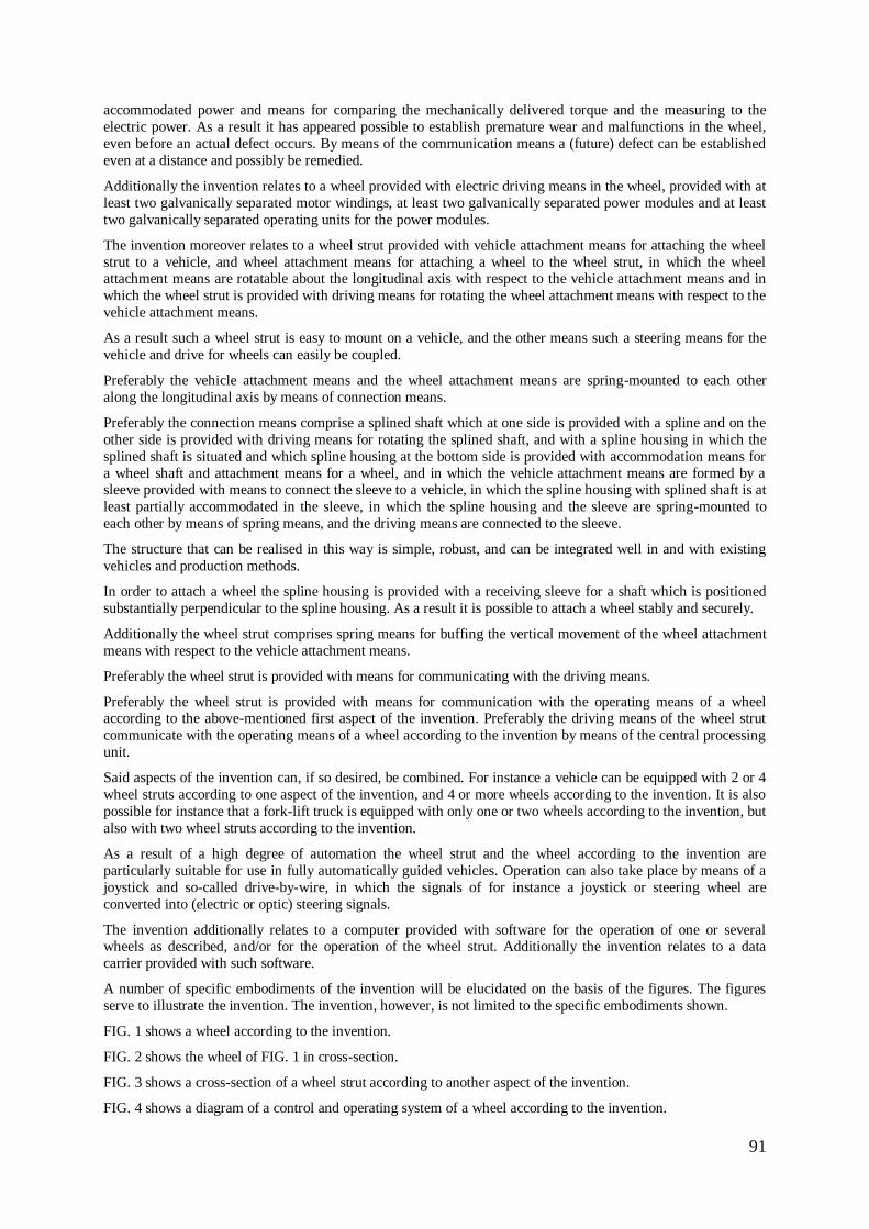
91
accommodated power and means for comparing the mechanically delivered torque and the measuring to the
electric power. As a result it has appeared possible to establish premature wear and malfunctions in the wheel,
even before an actual defect occurs. By means of the communication means a (future) defect can be established
even at a distance and possibly be remedied.
Additionally the invention relates to a wheel provided with electric driving means in the wheel, provided with at
least two galvanically separated motor windings, at least two galvanically separated power modules and at least
two galvanically separated operating units for the power modules.
The invention moreover relates to a wheel strut provided with vehicle attachment means for attaching the wheel
strut to a vehicle, and wheel attachment means for attaching a wheel to the wheel strut, in which the wheel attachment means are rotatable about the longitudinal axis with respect to the vehicle attachment means and in
which the wheel strut is provided with driving means for rotating the wheel attachment means with respect to the
vehicle attachment means.
As a result such a wheel strut is easy to mount on a vehicle, and the other means such a steering means for the
vehicle and drive for wheels can easily be coupled.
Preferably the vehicle attachment means and the wheel attachment means are spring-mounted to each other
along the longitudinal axis by means of connection means.
Preferably the connection means comprise a splined shaft which at one side is provided with a spline and on the
other side is provided with driving means for rotating the splined shaft, and with a spline housing in which the
splined shaft is situated and which spline housing at the bottom side is provided with accommodation means for
a wheel shaft and attachment means for a wheel, and in which the vehicle attachment means are formed by a sleeve provided with means to connect the sleeve to a vehicle, in which the spline housing with splined shaft is at
least partially accommodated in the sleeve, in which the spline housing and the sleeve are spring-mounted to
each other by means of spring means, and the driving means are connected to the sleeve.
The structure that can be realised in this way is simple, robust, and can be integrated well in and with existing
vehicles and production methods.
In order to attach a wheel the spline housing is provided with a receiving sleeve for a shaft which is positioned
substantially perpendicular to the spline housing. As a result it is possible to attach a wheel stably and securely.
Additionally the wheel strut comprises spring means for buffing the vertical movement of the wheel attachment
means with respect to the vehicle attachment means.
Preferably the wheel strut is provided with means for communicating with the driving means.
Preferably the wheel strut is provided with means for communication with the operating means of a wheel according to the above-mentioned first aspect of the invention. Preferably the driving means of the wheel strut
communicate with the operating means of a wheel according to the invention by means of the central processing
unit.
Said aspects of the invention can, if so desired, be combined. For instance a vehicle can be equipped with 2 or 4
wheel struts according to one aspect of the invention, and 4 or more wheels according to the invention. It is also
possible for instance that a fork-lift truck is equipped with only one or two wheels according to the invention, but
also with two wheel struts according to the invention.
As a result of a high degree of automation the wheel strut and the wheel according to the invention are
particularly suitable for use in fully automatically guided vehicles. Operation can also take place by means of a
joystick and so-called drive-by-wire, in which the signals of for instance a joystick or steering wheel are
converted into (electric or optic) steering signals.
The invention additionally relates to a computer provided with software for the operation of one or several wheels as described, and/or for the operation of the wheel strut. Additionally the invention relates to a data
carrier provided with such software.
A number of specific embodiments of the invention will be elucidated on the basis of the figures. The figures
serve to illustrate the invention. The invention, however, is not limited to the specific embodiments shown.
FIG. 1 shows a wheel according to the invention.
FIG. 2 shows the wheel of FIG. 1 in cross-section.
FIG. 3 shows a cross-section of a wheel strut according to another aspect of the invention.
FIG. 4 shows a diagram of a control and operating system of a wheel according to the invention.
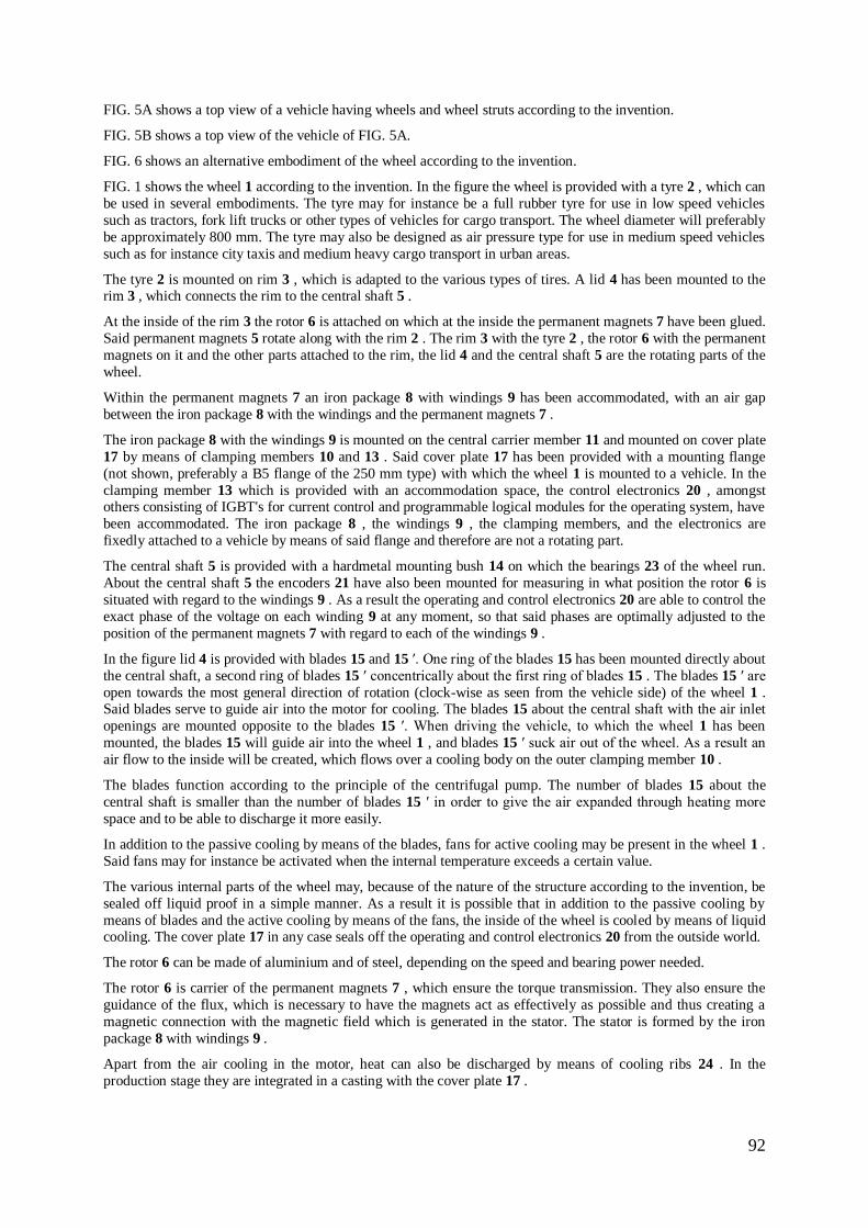
92
FIG. 5A shows a top view of a vehicle having wheels and wheel struts according to the invention.
FIG. 5B shows a top view of the vehicle of FIG. 5A.
FIG. 6 shows an alternative embodiment of the wheel according to the invention.
FIG. 1 shows the wheel 1 according to the invention. In the figure the wheel is provided with a tyre 2 , which can
be used in several embodiments. The tyre may for instance be a full rubber tyre for use in low speed vehicles
such as tractors, fork lift trucks or other types of vehicles for cargo transport. The wheel diameter will preferably
be approximately 800 mm. The tyre may also be designed as air pressure type for use in medium speed vehicles
such as for instance city taxis and medium heavy cargo transport in urban areas.
The tyre 2 is mounted on rim 3 , which is adapted to the various types of tires. A lid 4 has been mounted to the rim 3 , which connects the rim to the central shaft 5 .
At the inside of the rim 3 the rotor 6 is attached on which at the inside the permanent magnets 7 have been glued.
Said permanent magnets 5 rotate along with the rim 2 . The rim 3 with the tyre 2 , the rotor 6 with the permanent
magnets on it and the other parts attached to the rim, the lid 4 and the central shaft 5 are the rotating parts of the
wheel.
Within the permanent magnets 7 an iron package 8 with windings 9 has been accommodated, with an air gap
between the iron package 8 with the windings and the permanent magnets 7 .
The iron package 8 with the windings 9 is mounted on the central carrier member 11 and mounted on cover plate
17 by means of clamping members 10 and 13 . Said cover plate 17 has been provided with a mounting flange
(not shown, preferably a B5 flange of the 250 mm type) with which the wheel 1 is mounted to a vehicle. In the
clamping member 13 which is provided with an accommodation space, the control electronics 20 , amongst others consisting of IGBT's for current control and programmable logical modules for the operating system, have
been accommodated. The iron package 8 , the windings 9 , the clamping members, and the electronics are
fixedly attached to a vehicle by means of said flange and therefore are not a rotating part.
The central shaft 5 is provided with a hardmetal mounting bush 14 on which the bearings 23 of the wheel run.
About the central shaft 5 the encoders 21 have also been mounted for measuring in what position the rotor 6 is
situated with regard to the windings 9 . As a result the operating and control electronics 20 are able to control the
exact phase of the voltage on each winding 9 at any moment, so that said phases are optimally adjusted to the
position of the permanent magnets 7 with regard to each of the windings 9 .
In the figure lid 4 is provided with blades 15 and 15 ′. One ring of the blades 15 has been mounted directly about
the central shaft, a second ring of blades 15 ′ concentrically about the first ring of blades 15 . The blades 15 ′ are
open towards the most general direction of rotation (clock-wise as seen from the vehicle side) of the wheel 1 . Said blades serve to guide air into the motor for cooling. The blades 15 about the central shaft with the air inlet
openings are mounted opposite to the blades 15 ′. When driving the vehicle, to which the wheel 1 has been
mounted, the blades 15 will guide air into the wheel 1 , and blades 15 ′ suck air out of the wheel. As a result an
air flow to the inside will be created, which flows over a cooling body on the outer clamping member 10 .
The blades function according to the principle of the centrifugal pump. The number of blades 15 about the
central shaft is smaller than the number of blades 15 ′ in order to give the air expanded through heating more
space and to be able to discharge it more easily.
In addition to the passive cooling by means of the blades, fans for active cooling may be present in the wheel 1 .
Said fans may for instance be activated when the internal temperature exceeds a certain value.
The various internal parts of the wheel may, because of the nature of the structure according to the invention, be
sealed off liquid proof in a simple manner. As a result it is possible that in addition to the passive cooling by
means of blades and the active cooling by means of the fans, the inside of the wheel is cooled by means of liquid cooling. The cover plate 17 in any case seals off the operating and control electronics 20 from the outside world.
The rotor 6 can be made of aluminium and of steel, depending on the speed and bearing power needed.
The rotor 6 is carrier of the permanent magnets 7 , which ensure the torque transmission. They also ensure the
guidance of the flux, which is necessary to have the magnets act as effectively as possible and thus creating a
magnetic connection with the magnetic field which is generated in the stator. The stator is formed by the iron
package 8 with windings 9 .
Apart from the air cooling in the motor, heat can also be discharged by means of cooling ribs 24 . In the
production stage they are integrated in a casting with the cover plate 17 .
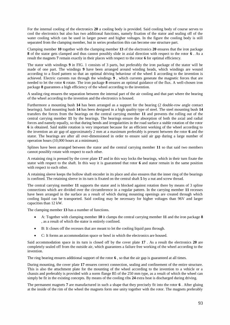
93
For the internal cooling of the electronics 20 a cooling body is provided. Said cooling body of course serves to
cool the electronics but also has two additional functions, namely fixation of the stator and sealing off of the
water cooling which can be used in larger power and higher voltages. In the figure the cooling body is still
separated from the clamping member, but in series production this can become one structure part.
Clamping member 10 together with the clamping member 13 of the electronics 20 ensures that the iron package
8 of the stator gets clamped and thus cannot possibly slide in axial direction with respect to the rotor 6 . As a
result the magnets 7 remain exactly in their places with respect to the rotor 6 for optimal efficiency.
The stator with windings 9 in FIG. 1 consists of 3 parts, but preferably the iron package of the stator will be
made of one part. The windings 9 have been arranged around winding heads, which windings are wound according to a fixed pattern so that an optimal driving behaviour of the wheel 1 according to the invention is
achieved. Electric currents run through the windings 9 , which currents generate the magnetic forces that are
needed to let the rotor 6 rotate. The iron package 8 ensures an optimal guidance of the flux. A well-chosen iron
package 8 guarantees a high efficiency of the wheel according to the invention.
A sealing ring ensures the separation between the internal part of the air cooling and that part where the bearing
of the wheel according to the invention and the electronics is housed.
Furthermore a mounting bush 14 has been arranged as a support for the bearing (2 double-row angle contact
bearings). Said mounting bush 14 has been designed in a high quality type of steel. The steel mounting bush 14
transfers the forces from the bearings on the central carrying member 11 and prevents the rolling out of the
central carrying member 11 by the bearings. The bearings ensure the absorption of both the axial and radial
forces and namely equally, so that during bends and irregularities in the road surface a stable rotation of the rotor 6 is obtained. Said stable rotation is very important because for an efficient working of the wheel according to
the invention an air gap of approximately 2 mm at a maximum preferably is present between the rotor 6 and the
stator. The bearings are after all over-dimensioned in order to ensure said air gap during a large number of
operation hours (10,000 hours at a minimum).
Splines have been arranged between the stator and the central carrying member 11 so that said two members
cannot possibly rotate with respect to each other.
A retaining ring is pressed by the cover plate 17 and in this way locks the bearings, which in their turn fixate the
stator with respect to the shaft. In this way it is guaranteed that rotor 6 and stator remain in the same position
with respect to each other.
A retaining sleeve keeps the hollow shaft encoder in its place and also ensures that the inner ring of the bearings
is confined. The retaining sleeve in its turn is fixated on the central shaft 5 by a nut and screw thread.
The central carrying member 11 supports the stator and is blocked against rotation there by means of 3 spline
connections which are divided over the circumference in a regular pattern. In the carrying member 11 recesses
have been arranged in the surface as a result of which during mounting openings are created through which
cooling liquid can be transported. Said cooling may be necessary for higher voltages than 96V and larger
capacities than 12 kW.
The clamping member 13 has a number of functions.
A: Together with clamping member 10 it clamps the central carrying member 11 and the iron package 8
, as a result of which the stator is entirely confined.
B: It closes off the recesses that are meant to let the cooling liquid pass through.
C: It forms an accommodation space or bowl in which the electronics are housed.
Said accommodation space in its turn is closed off by the cover plate 17 . As a result the electronics 20 are
completely sealed off from the outside air, which guarantees a failure free working of the wheel according to the invention.
The ring bearing ensures additional support of the rotor 6 , so that the air gap is guaranteed at all times.
During mounting, the cover plate 17 ensures correct connection, sealing and confinement of the entire structure.
This is also the attachment plate for the mounting of the wheel according to the invention to a vehicle or a
chassis and preferably is provided with a norm flange B5 of the 250 mm type, as a result of which the wheel can
simply be fit in the existing concepts. By means of the cooling ribs 24 extra heat is discharged during driving.
The permanent magnets 7 are manufactured in such a shape that they precisely fit into the rotor 6 . After gluing
at the inside of the rim of the wheel the magnets form one unity together with the rotor. The magnets preferably
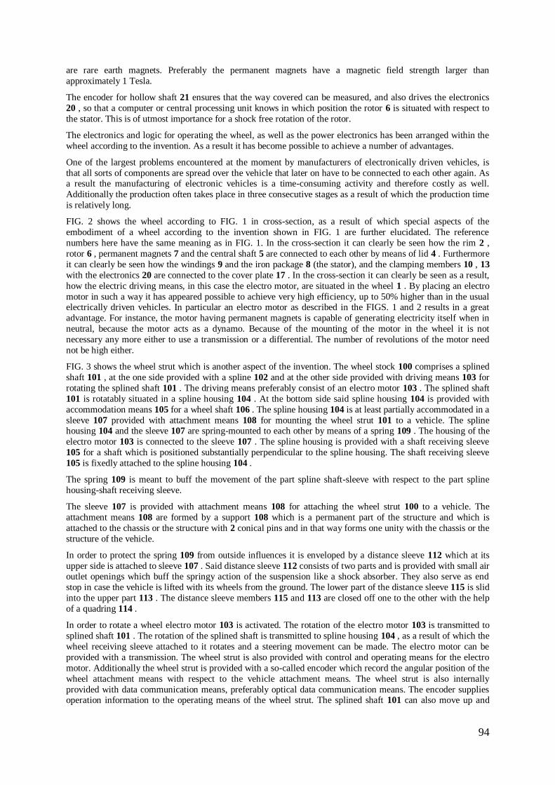
94
are rare earth magnets. Preferably the permanent magnets have a magnetic field strength larger than
approximately 1 Tesla.
The encoder for hollow shaft 21 ensures that the way covered can be measured, and also drives the electronics
20 , so that a computer or central processing unit knows in which position the rotor 6 is situated with respect to
the stator. This is of utmost importance for a shock free rotation of the rotor.
The electronics and logic for operating the wheel, as well as the power electronics has been arranged within the
wheel according to the invention. As a result it has become possible to achieve a number of advantages.
One of the largest problems encountered at the moment by manufacturers of electronically driven vehicles, is
that all sorts of components are spread over the vehicle that later on have to be connected to each other again. As a result the manufacturing of electronic vehicles is a time-consuming activity and therefore costly as well.
Additionally the production often takes place in three consecutive stages as a result of which the production time
is relatively long.
FIG. 2 shows the wheel according to FIG. 1 in cross-section, as a result of which special aspects of the
embodiment of a wheel according to the invention shown in FIG. 1 are further elucidated. The reference
numbers here have the same meaning as in FIG. 1. In the cross-section it can clearly be seen how the rim 2 ,
rotor 6 , permanent magnets 7 and the central shaft 5 are connected to each other by means of lid 4 . Furthermore
it can clearly be seen how the windings 9 and the iron package 8 (the stator), and the clamping members 10 , 13
with the electronics 20 are connected to the cover plate 17 . In the cross-section it can clearly be seen as a result,
how the electric driving means, in this case the electro motor, are situated in the wheel 1 . By placing an electro
motor in such a way it has appeared possible to achieve very high efficiency, up to 50% higher than in the usual electrically driven vehicles. In particular an electro motor as described in the FIGS. 1 and 2 results in a great
advantage. For instance, the motor having permanent magnets is capable of generating electricity itself when in
neutral, because the motor acts as a dynamo. Because of the mounting of the motor in the wheel it is not
necessary any more either to use a transmission or a differential. The number of revolutions of the motor need
not be high either.
FIG. 3 shows the wheel strut which is another aspect of the invention. The wheel stock 100 comprises a splined
shaft 101 , at the one side provided with a spline 102 and at the other side provided with driving means 103 for
rotating the splined shaft 101 . The driving means preferably consist of an electro motor 103 . The splined shaft
101 is rotatably situated in a spline housing 104 . At the bottom side said spline housing 104 is provided with
accommodation means 105 for a wheel shaft 106 . The spline housing 104 is at least partially accommodated in a
sleeve 107 provided with attachment means 108 for mounting the wheel strut 101 to a vehicle. The spline housing 104 and the sleeve 107 are spring-mounted to each other by means of a spring 109 . The housing of the
electro motor 103 is connected to the sleeve 107 . The spline housing is provided with a shaft receiving sleeve
105 for a shaft which is positioned substantially perpendicular to the spline housing. The shaft receiving sleeve
105 is fixedly attached to the spline housing 104 .
The spring 109 is meant to buff the movement of the part spline shaft-sleeve with respect to the part spline
housing-shaft receiving sleeve.
The sleeve 107 is provided with attachment means 108 for attaching the wheel strut 100 to a vehicle. The
attachment means 108 are formed by a support 108 which is a permanent part of the structure and which is
attached to the chassis or the structure with 2 conical pins and in that way forms one unity with the chassis or the
structure of the vehicle.
In order to protect the spring 109 from outside influences it is enveloped by a distance sleeve 112 which at its
upper side is attached to sleeve 107 . Said distance sleeve 112 consists of two parts and is provided with small air outlet openings which buff the springy action of the suspension like a shock absorber. They also serve as end
stop in case the vehicle is lifted with its wheels from the ground. The lower part of the distance sleeve 115 is slid
into the upper part 113 . The distance sleeve members 115 and 113 are closed off one to the other with the help
of a quadring 114 .
In order to rotate a wheel electro motor 103 is activated. The rotation of the electro motor 103 is transmitted to
splined shaft 101 . The rotation of the splined shaft is transmitted to spline housing 104 , as a result of which the
wheel receiving sleeve attached to it rotates and a steering movement can be made. The electro motor can be
provided with a transmission. The wheel strut is also provided with control and operating means for the electro
motor. Additionally the wheel strut is provided with a so-called encoder which record the angular position of the
wheel attachment means with respect to the vehicle attachment means. The wheel strut is also internally
provided with data communication means, preferably optical data communication means. The encoder supplies operation information to the operating means of the wheel strut. The splined shaft 101 can also move up and
95
down in the spline housing, as a result of which springing becomes possible. The vehicle attachment means can
as a result move along the longitudinal axis with respect to the wheel attachment means.
The spline housing 104 is the part of the wheel suspension that rotates and moves up and down. A wheel can be
attached to the spline housing 104 by means of a B5 standard flange. A brake device can be also mounted to the
rear side by means of the central shaft 12 / 106 . The central shaft 12 / 106 can also be equipped with a flange on
which a wheel in neutral can be attached whereas on the other side disc brakes can be mounted. When the wheel
according to the invention is mounted this part can be left out.
The triangle support is a point of adhesion for a triangle. Said triangle is available on the market and makes it
possible to increase the load of the spring leg from 1500 kg allowed load bearing capacity to 4000 kg allowed load bearing capacity. By using the triangle bending forces are no longer exerted on the suspension.
An extended central shaft of a wheel according to the invention is necessary for the mounting of a wheel and
may also serve to mount discs of a brake system.
The spring ensures a comfortable road holding of the vehicle on which the wheel and the suspension have been
mounted. In the 4 ton version with triangle the spring is indeed completely pressed in but ensures a minimal
spring pressure of 1500 kg when the vehicle is positioned inclined and one of the wheels threatens to come off
the ground.
The rubber O-ring ensures the buffering of the spline housing 104 in the unlikely event of the load becoming so
high that the spline housing 104 bumps against the support.
Description of the Electronic Control for Operating the Synchronous Motor in the Wheel According to the
Invention.
The electronic control for the wheel according to the invention is built up modularly from several elements. The
several elements are hierarchically adjusted to each other. The following elements can be distinguished.
1. Power Modules
At the lowest step IGBT main current modules have been used. The structure present in said IGBT main current
modules renders them highly reliable in themselves already and guarantees a low heat emission and an optimal
efficiency. The main current modules control the current through the windings. The windings are divided into
three groups, each having another phase. Per winding there are two main current modules. The main current
modules are driven by a higher step, namely:
2. Current Regulators
At the second step 2 IGBT main current modules are connected to a current regulator and driven by the current
regulator. Together with a separate current sensor working according to the Hall principle (Hall sensor) they form an independent end step that controls the current in the accompanying motor winding. In this step the
module and the current regulator are already galvanically separated from the operating electronics. A current
regulator having two main current modules and Hall sensor are further called 4Q-modules. The main current
modules with current regulator form a control system. There is a control system per winding.
3. Vector Generator
The vector generator supplies an operating value to the so-called 4Q-modules (step 1 and 2 ), which thus
generate a magnetic field vector by means of windings of the synchronous motor and thus determine the moment
of torque.
A so-called encoder or resolver, a measuring apparatus that very accurately measures the angle or the number of
revolutions, makes the present position of the rotor with respect to the stator known to the vector generator. The
quick calculation of the rotor position, which is derived from the sine/cosine signals of the resolver and the
feedback value connected to it, ensures an optimal setting of the field vectors of the motor together with programmable logic modules, the so-called FPGA's.
The entire function of the vector generator, due to the combination of a micro processor and the FPGA's, can be
programmed entirely over an optical fibre cable. This means that new data or changes needed for a special use
can immediately be implemented (by telephone or internet) in the wheel according to the invention that is
already in operation. Said changes do not only regard the software of the FPGA's, but also the hardware of the
modules. It is for instance possible to change the relation in the motor itself when a winding or a module should
fail so that the wheel can remain functioning. The vector generator forms the operating system. The encoder and
the Hall sensors with the accompanying electronics in the described embodiment form the measuring system.
4. CPU or Central Processing Unit
96
The first three stages are housed together in the wheel. The CPU is situated outside the wheel and communicates
with the several wheels according to the invention that may be present on a car, by means of an optical ring data
bus line (ORDABUL). It is also able to carry out calculations needed for the AGV's (automatic guided vehicles)
regarding the road covered, odometrics when taking bends and diagnosing the complete driving concept. Each
stage guards and reports the data important for the operational situation to the CPU. An error report is
immediately reported to the stage above and this one immediately reacts by taking the necessary measures,
before damage may arise. The stage above is able to activate an emergency program, which reacts to the error in
the correct manner. As a result an error in one module hardly influences the entire vehicle.
The modular system makes it possible to make a simple error diagnosis and to quickly locate the relevant components without having to subsequently perform complex adjusting or setting activities.
An important difference with the usual control of Asynchronous/synchronous motors is the fact that in a
preferred embodiment all motor windings are divided into three groups, each preferably consisting of 30
independent windings, electrically separated from each other and each winding being driven by its own 4Q-
module. Here the 4Q-modules are merely connected to each other by means of the power supply voltage, as a
result of which the following advantages arise:
1: Only two phases of the normal 3-phase drive are guarded and controlled. The currents in the third
phase are calculated from the behaviour of the other two phases. This means a much greater freedom in
operating the electronics, and for instance in buffering the failure of one or more modules.
2: The current distribution can be adjusted exactly so that each motor winding generates the same field
strength. As a result the actual moments of torque in each winding, generated by the field, can be adjusted and are independent from the irregularities in the electric variables of the separate windings.
3: The magnetic tolerances of each winding can be calibrated separately by means of the vector
generator.
4: When a 4Q-module fails or one of the windings has short circuited, the motor can still remain
operational. A fuse or relay is able to separate the defect module or phase of the other 2 4Q-modules or
phases without influencing them. In this way the motor is still able to brake or, when several wheels are
used, to support them. The advantages of a stage-wise structure come to the fore here in particular.
The functionality of the electronics described and their connection is further elucidated in FIG. 4. By means of a
block diagram the connection is schematically shown here and the hierarchy of wheels, wheel struts and other
control and operating means in an electrically driven vehicle, such as for instance a remote or automatically
controlled vehicle. A central processing unit or computer 200 controls the overall exchange of data between the several parts, and ensures the possible automatic control of the vehicle. The computer 200 is connected to energy
management system 300 , namely the batteries, possible generators, fuel cells or solar panels, by means of data
communication lines, for instance optical data communication lines. Additionally the computer 200 is connected
to a display screen 400 on which the data are presented regarding the status of the various systems. The central
computer 200 is also connected to various sensors that supply information regarding the vehicle position,
possible obstacles, inside climate, and the like. The central computer moreover is connected to for instance two
or more wheel struts 100 according to the invention. The numbers in the figure here correspond to the parts
already described.
The central computer 200 is moreover connected to at least one or more wheels 1 according to the invention. It
can be seen that the wheel comprises three groups of windings 9 , 9 / 1 and 9 / 11 , control systems 32 , 32 / 1
and 32 / 11 for each group, and measuring systems 30 , 30 / 1 and 30 / 11 for each group. Additionally the wheel
comprises the already described encoder 31 , which supplies data regarding the relative position of the rotor with respect of the stator to the operating system 33 superior to it. In the figure the three groups of the preferably in
total at least 30 windings 9 , 9 / 1 and 9 / 11 in a wheel 1 according to the invention are shown. The windings 9
are preferably divided into three groups, each having another phase φ 1 , φ 2 and φ 3 . The current through each
group of windings 9 , 9 / 1 and 9 / 11 is measured by a Hall sensor 30 . The value measured is passed on to the
control system 32 . The control system 32 controls the current through a group of windings by means of 2
IGBT's. The control systems 32 are operated by an operating system 33 . Said operating system also receives
data from an encoder 31 , which supplies angle information about the rotor with respect to the stator. As a result
the operating system 33 is capable of choosing a good phase setting for an optimized working. The operating
system 33 is coupled to a central processing unit 200 in a vehicle by means of data communication means 34 ,
preferably suitable for optical data communication.
FIG. 5A shows a top view of a vehicle provided with four wheels 1 according to the invention. Said wheels 1 are each attached to a wheel strut 100 according to another aspect of the invention that has also been described. Said

97
wheel struts are each provided with means in the wheel strut as a result of which each wheel is able to rotate and
in which way it is possible to drive the vehicle. The vehicle is furthermore equipped with a central processing
unit 200 and batteries and control systems 300 for them. In FIG. 5B a side view of the vehicle of FIG. 5A is
shown.
FIG. 6 shows an alternative embodiment of the wheel according to the invention. The reference numbers
correspond as much as possible to those in FIGS. 1 and 2. The vehicle side is shown with arrow A. The wheel
according to FIG. 6 is provided with for instance water cooling. The inlet and outlet, respectively, of the cooling
liquid is indicated by number 30 . The inlet and outlet 30 debouch in a space 31 around the shaft through which
cooling liquid circulates. In this embodiment the measuring, control and operating means have been arranged in space 32 . The electronics are arranged with the print plates oriented towards a vehicle. The cooling liquid,
preferably water, mainly serves to cool the windings.
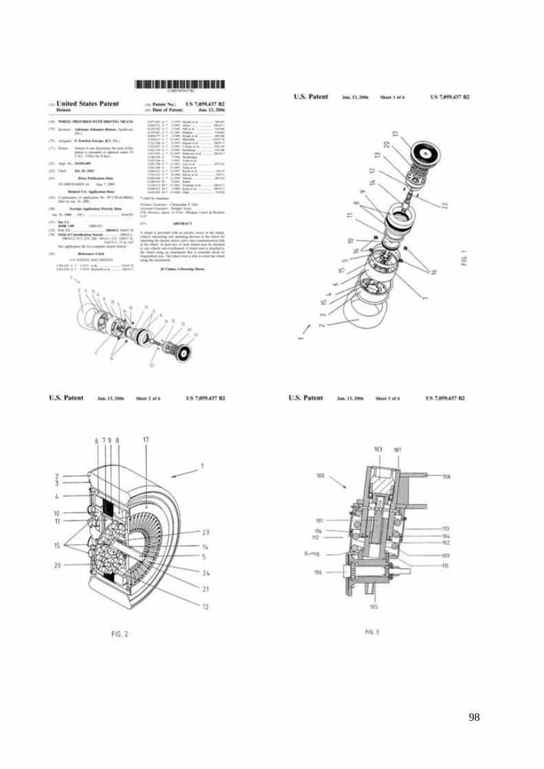
98
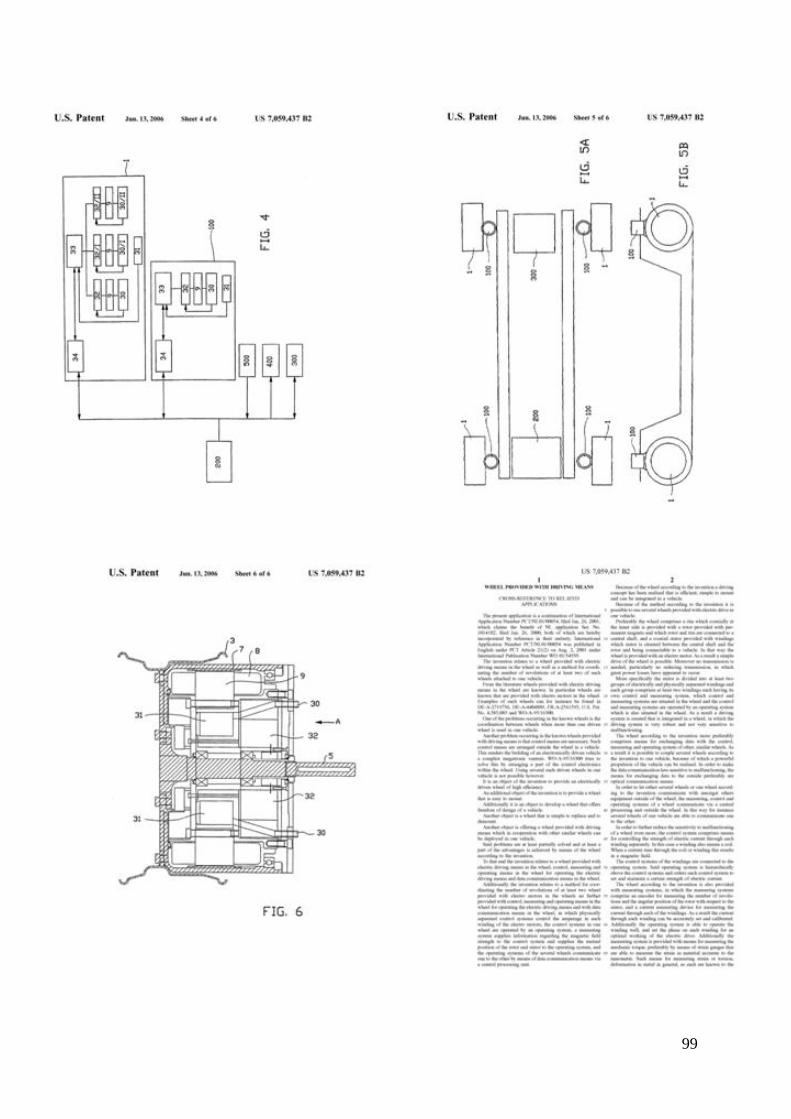
99
100
101

102
Appendix 2: Certification fuel consumption by TNO
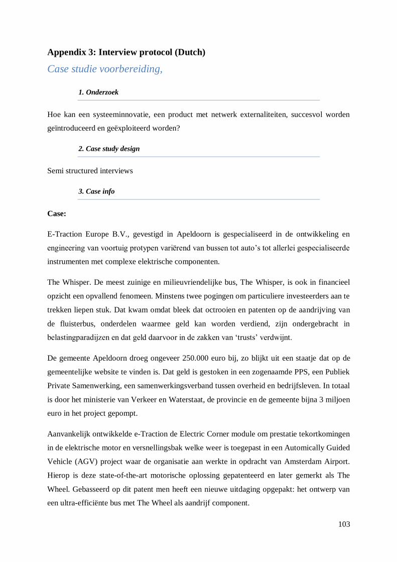
103
Appendix 3: Interview protocol (Dutch)
Case studie voorbereiding,
1. Onderzoek
Hoe kan een systeeminnovatie, een product met netwerk externaliteiten, succesvol worden
geïntroduceerd en geëxploiteerd worden?
2. Case study design
Semi structured interviews
3. Case info
Case:
E-Traction Europe B.V., gevestigd in Apeldoorn is gespecialiseerd in de ontwikkeling en
engineering van voortuig protypen variërend van bussen tot auto‟s tot allerlei gespecialiseerde
instrumenten met complexe elektrische componenten.
The Whisper. De meest zuinige en milieuvriendelijke bus, The Whisper, is ook in financieel
opzicht een opvallend fenomeen. Minstens twee pogingen om particuliere investeerders aan te
trekken liepen stuk. Dat kwam omdat bleek dat octrooien en patenten op de aandrijving van
de fluisterbus, onderdelen waarmee geld kan worden verdiend, zijn ondergebracht in
belastingparadijzen en dat geld daarvoor in de zakken van „trusts‟ verdwijnt.
De gemeente Apeldoorn droeg ongeveer 250.000 euro bij, zo blijkt uit een staatje dat op de
gemeentelijke website te vinden is. Dat geld is gestoken in een zogenaamde PPS, een Publiek
Private Samenwerking, een samenwerkingsverband tussen overheid en bedrijfsleven. In totaal
is door het ministerie van Verkeer en Waterstaat, de provincie en de gemeente bijna 3 miljoen
euro in het project gepompt.
Aanvankelijk ontwikkelde e-Traction de Electric Corner module om prestatie tekortkomingen
in de elektrische motor en versnellingsbak welke weer is toegepast in een Automically Guided
Vehicle (AGV) project waar de organisatie aan werkte in opdracht van Amsterdam Airport.
Hierop is deze state-of-the-art motorische oplossing gepatenteerd en later gemerkt als The
Wheel. Gebasseerd op dit patent men heeft een nieuwe uitdaging opgepakt: het ontwerp van
een ultra-efficiënte bus met The Wheel als aandrijf component.

104
Na verschillende prototypes is de „e-Traction Bus‟ met codenaam X97 geëvolueerd in een
levensvatbare technology. Onafhankelijk onderzoek door TNO Automotive liet zien dat het
brandstofverbruik net onder de 15mpg ligt met minder dan de helft van de co2 emissie van
overige bestaande commerciële bussen.
Stadsbussen uitgerust met The Wheel zijn nu in dienst genomen in Apeldoorn en toekomstig
in Rotterdam. E-Traction is momenteel bezig met het ontwerpen van meer types van The
Wheel om het brandstofverbruik van bussen, SUV‟s, monorails en personenauto‟s verder te
ontwikkelen.
105
Adresgegevens:
Bezoekadres
[Adres]
Postadres
Telefoon
[Telefoonnummer]
Contactpersoon: [Voornaam] [Achternaam]
[foto]
4. Case studie vragen/onderwerpen
Interview protocol
Noteren:
- Tijdstip interview;
- Wel/geen derden aanwezig;
- Plaats van het interview;
- Naam geïnterviewde;
- Interviewnummer.

106
Gespreksintroductie
Goedemorgen mijn naam is Willem Cornelissen en ik studeer Bedrijfswetenschappen aan de
Universiteit van Twente.
Op dit moment ben ik bezig met het afronden van mijn opleiding met als afstudeer richting
innovatie en ondernemerschap. Hiervoor doe ik een afstudeeropdracht, wat ik uitvoer binnen
de Universiteit. Met mijn onderzoek wil in kaart brengen hoe een systeeminnovatie succesvol
te introduceren en exploiteren in de automotive industrie.
Doormiddel van dit interview hoop ik een beter inzicht te krijgen in de factoren die
doorslaggevend zijn in het laten slagen of mislukken van deze innovaties.
Dit interview wordt opgenomen, zodat er voor mij geen informatie verloren gaat en zodat ik
niet hoef te schrijven tijdens het interview.
Deze opname wordt alleen voor mijn onderzoek gebruikt en zal volledig anoniem zijn. Mijn
onderzoek baseert zich op conclusies van alle interviews. Eventuele citaten zijn anoniem.
Tevens zal ik het interview naar u toesturen zodat u de gelegenheid heeft om mij te
controleren.
Het interview duurt zo rond een uur om alle zaken aan bod te kunnen laten komen. De
opname zal ik gebruiken om dit interview zo correct mogelijk te verwerken daarna wordt de
opname gewist.
Zijn er opmerkingen of vragen naar aanleiding van het voorafgaande?
Het interview is als volgt opgebouwd. Allereerst komen enkele vragen over de eigenschappen
van uw organisatie en de introductie in het project, vervolgens enkele vragen over de
samenwerking en de coördinatie van het project.
Als alles duidelijk is dan zou ik nu graag beginnen.
107
Vragenlijst Interview
Introductie
De intentie van dit interview is om meer te weten te komen over hoe [partij] is betrokken bij
de ontwikkeling, ondersteuning, introductie en exploitatie van de fluisterbus.
1. Zou u kort willen toelichten hoe u, als [partij], bij het project betrokken bent geraakt
bij het project?
Deelname aan het project
2. Zou u kort kunnen toelichten waarom u juist voor deelname aan het project De
Fluisterbus heeft gekozen?
3. Hoe zou u de rol van de [partij] binnen het project omschrijven?
4. In hoeverre zijn beslissingen of ontwikkelingen binnen andere partijen van invloed
geweest op uw rol en beslissingen als gemeente?
5. Welke gevolgen heeft de deelname aan dit project voor uw organisatie gehad?
Toelichting: wat heeft u moeten opzetten om bij te dragen aan de innovatie. Wat heeft
uw afdeling organisatorisch, praktisch, etc. bijgedragen en hoe heeft uw afdeling
beïnvloed.
6. Heeft u op het gebied van regelgeving wijzigingen doorgevoerd ter ondersteuning van
het project?
Toelichting: vanaf de start van het project tot en met de uiteindelijke realisatie.
7. Heeft u nog op andere wijze een bijdrage geleverd aan het project?
Toelichting: door middel van subsidies bijvoorbeeld, of door een gegarandeerde
afname van bussen.
8. Heeft u aan de participatie van het innovatieproces nog eisen gesteld, of voorwaarden
waar aan voldaan moet worden?
9. Indien ja, welke voorwaarden?
10. Wat is de achterliggende gedachte achter deze voorwaarden?
11. Hoe verliep de coördinatie van het project?
Toelichting: Was er bijvoorbeeld één leidende organisatie of een intensieve
samenwerking tussen verschillende partijen.
12. Heeft u ook samengewerkt met overige [partij gerelateerd]?
13. Wat was de aard van deze samenwerking?

108
Toelichting: was dit bijvoorbeeld op het gebied voor het wijzigen van regelgeving.
14. Hoe zou hier in andere bestuurslagen ondersteuning aan projecten als de fluisterbus
kunnen worden gegeven?
Afsluiting
15. Wat zijn volgens u de belangrijkste uitkomsten van het project, afgezien van de
ecologische voordelen wat de uitvinding met zich meebrengt?
16. Is het mogelijk om u voor eventueel aanvullende vragen, telefonisch of via e-mail te
benaderen?
17. Graag zou ik voor het onderzoek meer deelnemers aan het project binnen uw
organisatie willen interviewen, zou u mij hiermee in contact willen brengen?
18. Heeft u zelf nog opmerkingen, suggesties of vragen?
19. Bedankt voor uw tijd en inzet.

109
Belscript
Goede….. mijn naam is Willem Cornelissen van de Universiteit van Twente. Ik ben op zoek
naar Dhr./Mevr.
Aanwezig: Goede….. U spreekt met Willem Cornelissen van de Universiteit Twente.
(spreekt u mee) Ik neem contact met u op in het kader van de innovatie de fluisterbus,
of Whisper genoemd.
Op dit moment ben ik bezig met het afronden van mijn opleiding bedrijfswetenschappen.
Hiervoor doe ik een afstudeeropdracht, wat ik uitvoer binnen de Universiteit.
Met mijn onderzoek wil in kaart brengen hoe een systeeminnovatie succesvol kan worden
geïntroduceerd in de automotive industrie.
Om hier meer inzicht in te krijgen voer ik een zogenaamde case study uit naar de Whisper.
Nou is mijn vraag of het mogelijk is dat ik bij u langs kom om u doormiddel van een kort
interview u enkele vragen te stellen.
Ja: (datum, tijd noteren)
Nee: Dat is erg jammer mocht nog van gedacht veranderen dan kunt u mij op dit nummer
bereiken , en dan wens ik u nog een fijne dag.
Niet aanwezig: Dat is jammer en wanneer kan ik Dhr/Mevr... Het beste bereiken?
(datum en tijd noteren)