introduction to collidoscope - soundsoftware.ac.uk · introduction to collidoscope (v0.2)...
TRANSCRIPT

Introduction to Collidoscope (v0.2)
Collidoscope is a table-top granular synthesizer unit that allows users to create impromptu whimsical sounds and play with them straight away. It is a collaborative instruments and it sports two independent synthesis engines so that multiple users can play together and share their experience. Each engine comes with a visual wave on the screen, that displays the sound and gives feedback on the user actions.
Figure 1: The new version of Collidoscope
Recording new sound You start by recording some sound using the embedded microphone. When you press the record
button a 2 seconds sample is recorded in the unit. As you record, a waveform with your sound is
displayed on the screen. If you want to record a new sound just press the record button again and a
new 2 seconds wave will be recorded and will replace the old one.
The waveform is your raw material to create new timbres but first you need to select the bit of
sound you want to work with.
Making a Selection In Collidoscope you make sound by playing a selection of the recorded wave. By moving the big
horizontal knob left and right along the wave, you can set the selection start. By turning the knob,
you can set the size of the selection: clockwise to increase the size and anticlockwise to shrink it. The
maximum size of the selection is 37 bars (or chunks); the minimum size is 1 chunk.

Looping/playing the selection If you flick the loop switch/button, the selection will start looping. You will see a white cursor that
goes from left to right and indicates the play position at the current time. If you press the middle C
of the keyboard you will get the same result as the looping. However, the other keys will play the
selection with higher or lower pitch according to the chromatic scale of the piano. You can use the
octave up/down button of the keyboard to play all the notes of the piano.
The looper is meant to allow the user to fiddle with the controls without having to hold the keyboard
keys; however, the keyboard and the looper are independent. That is, the piano will play regardless
of whether the looper is on or off.
Note that you can move the selection and change its size as you play, so as to experiment with the
sound of other parts of the wave in real time.
Filter If you tweak the filter cut-off parameter, a low-pass filter effect will be applied to the output of
Collidoscope. A low-pass filter cuts the high frequencies of the sound and makes the output darker
and in general lower in volume. All the frequencies above the filter cut-off frequency are cut. The
cut-off parameter ranges from 22050Hz (no cut) to 200Hz (maximum cut).
As you turn the filter up and down you’ll see that the selection colour will become respectively
brighter or darker, to reflect visually what’s happening to the sound.
Granular engine By tweaking the grain duration parameter, you actually trespass to the granular domain.
We can indeed define the wave selection more properly as a grain. A grain is a piece of sound, to
which a particular amplitude envelope is applied: a bell-shaped curve called Hann envelope, that
makes it fade in and out smoothly when the grain is played.
Once a grain is triggered, it plays from the beginning to the end. There can be many grains playing
together at the same time.
The selection start defines where the grain starts, whereas the selection size defines:
The grain duration: how long a grain is or how much audio it is made of, if you like;
The trigger rate of the grain: normally a new grain is triggered exactly as soon as the
previous one has finished playing. This is what gives the repetitive looping effect.
However, when the grain duration parameter is cranked up, the duration of the grain is increased by
multiplying it by a coefficient. So for instance, if the coefficient is 2, then the grain will last twice as
long as the selection size. The coefficient ranges from 1 to 8.
Note though that the trigger rate is only affected by the selection size and it stays the same
regardless of the duration parameter. This means that, when the duration parameter is greater than
1, a new grain is triggered before the previous one has finished playing and many grains (up to eight
in fact) start overlapping with each other.
Thanks to the bell shaped envelope the grains overlap in a way that they do not go on each other’s
way too much. They rather start building up an eerie sound that’s very characteristic of granular
synthesis.
The best way to achieve such eerie sound is to set the selection size very small and to crank up the
grain duration to the maximum.
When the grain duration is cranked up, the visual wave starts to emit particles, to convey visually
what’s happening in audio.
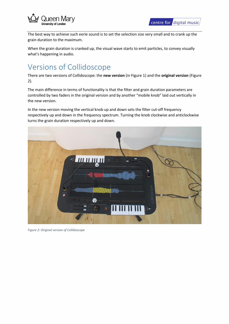
Versions of Collidoscope There are two versions of Collidoscope: the new version (in Figure 1) and the original version (Figure
2).
The main difference in terms of functionality is that the filter and grain duration parameters are
controlled by two faders in the original version and by another “mobile knob” laid out vertically in
the new version.
In the new version moving the vertical knob up and down sets the filter cut-off frequency
respectively up and down in the frequency spectrum. Turning the knob clockwise and anticlockwise
turns the grain duration respectively up and down.
Figure 2: Original version of Collidoscope

Building Collidoscope This paragraph gives an overview of all the electrical components of Collidoscope.
Figure 3 shows how they are connected together.
Figure 3: Architecture of Collidoscope
Components Collidoscope was built with relatively cheap set of components. Let’s see them in details.
Raspberry Pi 3, running Raspbian Jessie operating system
The Raspberry Pi runs all the visuals and sounds and is exclusively controlled via MIDI. See the
document Collidoscope Software Instruction for installing and running the CollidoscopeApp software
on the Raspberry Pi.
Link: https://www.raspberrypi.org
Teensy++ 2.0 microcontroller
The Teensy gathers all the sensor information (knobs, buttons etc.) and sends it as MIDI messages to
the Pi. It is connected to the Raspberry Pi via USB cable. Note that the Teensy can be configured to
become a class-compliant USB MIDI device and so doesn’t need any additional driver to work with
the Pi.

See the document Collidoscope Software Instruction for installing and running the
CollidoscopeTeensy software on the Teensy
Link: https://www.pjrc.com/store/teensypp.html
Focusrite scarlett 2i2 audio interface
The audio interface is connected to the Raspberry Pi via USB cable. It receives audio via the
microphones and it outputs audio through the connected speakers. Possibly other interfaces can be
used as well, as long as they have two microphone inputs and two outputs. The Scarlett 2i2 though is
proven to work seamlessly with the Raspberry Pi.
Link: http://focusrite.com
IMG Stage Line DMG700 Dynamic Gooseneck Microphone (XLR connection)
These are cardioid microphones, so the sound is picked up mostly from the front. You can try
different types of microphones of course and see if the recording is satisfying enough.
Speakers
Any speakers will do as long as they can be connected to the audio interface.
Monitor
Collidoscope uses one single monitor, overlaid with a sheet of acrylic to separate it in two different
parts, with one wave each. Both waves are drawn by the CollidoscopeApp. The yellow wave is drawn
upside-down to accommodate the instrument for two players standing in front of each other.
The monitor is connected to the Raspberry Pi through an HDMI cable. Any monitor with an HDMI
input can be used. Write down the resolution of your monitor in pixel, as this will be needed when
launching the CollidoscopeApp on the Raspberry Pi. (See Collidoscope Software Instructions for more
info on this)
For the original Collidoscope we used an LG 21:9 UltraWide 25UM65.
For the new Collidoscope we tried both an Asus MX299Q 29 inch Widescreen and a Dell 29
UltraSharp Monitor. The latter turned out to be a much better choice for the unit.
MIDI keyboards
Any USB compliant MIDI keyboard can be used
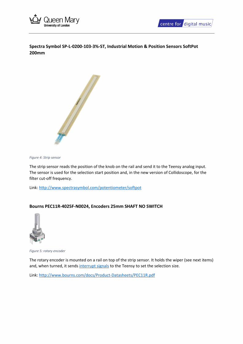
Spectra Symbol SP-L-0200-103-3%-ST, Industrial Motion & Position Sensors SoftPot
200mm
Figure 4: Strip sensor
The strip sensor reads the position of the knob on the rail and send it to the Teensy analog input.
The sensor is used for the selection start position and, in the new version of Collidoscope, for the
filter cut-off frequency.
Link: http://www.spectrasymbol.com/potentiometer/softpot
Bourns PEC11R-4025F-N0024, Encoders 25mm SHAFT NO SWITCH
Figure 5: rotary encoder
The rotary encoder is mounted on a rail on top of the strip sensor. It holds the wiper (see next items)
and, when turned, it sends interrupt signals to the Teensy to set the selection size.
Link: http://www.bourns.com/docs/Product-Datasheets/PEC11R.pdf

Spectra Symbol WP-M1-01-03-014-DI wiper
Figure 6: wiper
The wiper exerts pressure on the strip sensor for it to sense the position of the knob.
Silver aluminium knob Straw hat type, 38mm
Figure 7: aluminium knob
The aluminium knob is placed on the shaft of the rotary encoder.
Metal Pushbutton - Momentary (16mm, Red)
Figure 8: push button
Button to start recording. The button is also connected to a digital output of the teensy for the led
ring to be lit.
12V Heavy Duty HD On / Off Metal Toggle Flick Switch Car Dash K875
Figure 9: toggle flick switch
Switches the loop play on/off in the original version of Collidoscope.

Series 48m-ss (solid-state) panel sealed metal pushbutton switch
Figure 10: 48m-ss Push button
Switches the loop play on/off in the new version of Collidoscope.
Link: http://www.itwswitches.com/S48M-SS.shtml
Bourns Motorized Slide Potentiometer
Figure 11: Slide Potentiometer
In the original version the sliders control the filter cut-off frequency parameter and the grain
duration parameter. The motor is not used in Collidoscope so you can use non-motorized sliders as
well.
Link: https://www.bourns.com/data/global/pdfs/PSM.pdf
Connecting the Sensors to the Teensy board The sensors need to be connected to specific analog and interrupt pins in order for the Collidoscope
software running on the Teensy to work properly (See Collidoscope Software Instructions for more
info on the Teensy software).
The table below reports to which pin each sensor must be connected.
See this link for Teensy++ 2.0 pin assignment (scroll down in the page for Teensy 2.0). The codes
used in the table below (F0, F2 etc.) are actually on the board; except the interrupts codes, which
are listed on the side.
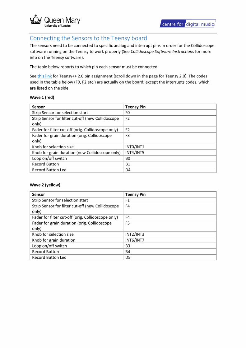
Wave 1 (red)
Sensor Teensy Pin
Strip Sensor for selection start F0
Strip Sensor for filter cut-off (new Collidoscope only)
F2
Fader for filter cut-off (orig. Collidoscope only) F2
Fader for grain duration (orig. Collidoscope only)
F3
Knob for selection size INT0/INT1
Knob for grain duration (new Collidoscope only) INT4/INT5
Loop on/off switch B0
Record Button B1
Record Button Led D4
Wave 2 (yellow)
Sensor Teensy Pin
Strip Sensor for selection start F1
Strip Sensor for filter cut-off (new Collidoscope only)
F4
Fader for filter cut-off (orig. Collidoscope only) F4
Fader for grain duration (orig. Collidoscope only)
F5
Knob for selection size INT2/INT3
Knob for grain duration INT6/INT7
Loop on/off switch B3
Record Button B4
Record Button Led D5

The Teensy PCB board
Figure 12: Collidoscope pcb for Teensy
The Collidoscope pcb (printed circuit board) for the Teensy makes it easy to plug and unplug sensors
to the Teensy inputs and output without the need of breadboards or solder iron.
Besides the pcb itself, you will also need two additional types of components to use it:
1. Molex KK 2.54mm Pitch PCB Headers with Straight Friction Lock, 6410 Series
The three headed pins mounted on the board in Figure 12 and 13.
2. TinkerKit Cable
The orange/red/black cable in Figure 12.
The PCB headers that you see in the Figure 12 and 13 feature three pins: one for power, voltage and
ground and map to the related Teensy pins. Each header has the same code as the Teensy pins ( F1,
F2, C1 etc.)
The interrupts of the Teensy are mapped to the pcb header in pairs: INT0/INT1, INT2/INT3, INT4/IN5
and INT6/INT7. The codes of each header are engraved in the pcb as you can see in Figure 13.
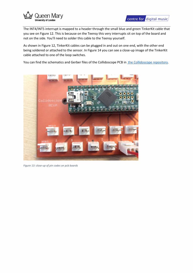
The INT4/INT5 interrupt is mapped to a header through the small blue and green TinkerKit cable that
you see on Figure 12. This is because on the Teensy this very interrupts sit on top of the board and
not on the side. You’ll need to solder this cable to the Teensy yourself.
As shown in Figure 12, TinkerKit cables can be plugged in and out on one end, with the other end
being soldered or attached to the sensor. In Figure 14 you can see a close-up image of the TinkerKit
cable attached to one of the loop switches.
You can find the schematics and Gerber files of the Collidoscope PCB in the Collidoscope repository.
Figure 13: close-up of pin codes on pcb boards
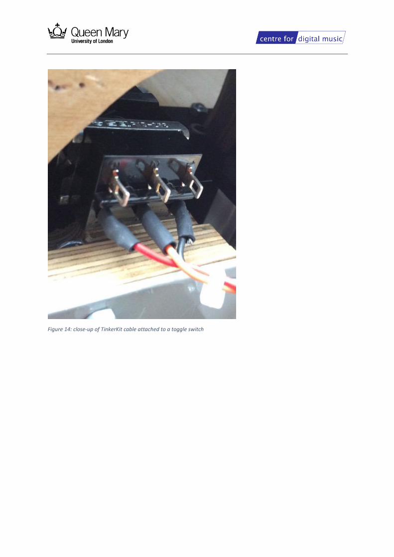
Figure 14: close-up of TinkerKit cable attached to a toggle switch