introduction to design of seismic force-resisting systems ... · instructional material...
TRANSCRIPT

Instructional Material Complementing FEMA P-1051, Design Examples Wood Background - 1
Disclaimer
Includes materials developed by Peter
Somers S.E. and Steve Pryor, S.E.
Introduction to Design of
Seismic Force-Resisting
Systems in Wood Light-
Frame Construction
Kelly Cobeen, S.E.

Instructional Material Complementing FEMA P-1051, Design Examples Wood Background - 2
• Introduction to wood design and construction &
Basic wood properties
• Shear Walls
• Diaphragms
• Anchorage of concrete and masonry walls
Wood Design Background
Outline

Instructional Material Complementing FEMA P-1051, Design Examples Wood Background - 3
Introduction to Wood Design and
Construction

Instructional Material Complementing FEMA P-1051, Design Examples Wood Background - 4
• Traditionally, many simple wood structures have been designed without
"engineering"
• Over time, rules of how to build have been developed, most recently in the
International Residential Code (IRC)
• For the lateral system, the "dedicated" vertical element is referred to as a
braced wall panel, which is part of a braced wall line
• Based on SDC and number of stories, rules dictate the permissible spacing
between braced wall lines, and the spacing of braced wall panels within braced
wall lines
(Also referred to as
“Conventional Construction”)
Wood Design and
Construction:
Prescriptive

Instructional Material Complementing FEMA P-1051, Design Examples Wood Background - 5
• If a structure does not meet the code requirements for "prescriptive" or
"conventional" construction, it must be "engineered"
• As in other engineered structures, wood structures are only limited by the
application of good design practices applied through principles of mechanics (and
story height limitations in the code)
• A dedicated system of horizontal and vertical elements, along with complete
connectivity, must be designed and detailed.
Wood Design and
Construction:
Engineered

Instructional Material Complementing FEMA P-1051, Design Examples Wood Background - 6
• ASCE 7-16
• AWC NDS, 2015 Edition – wood framing and connections
• AWC SDPWS, 2015 Edition – shears, diaphragms, and anchorage
Wood Design and Construction

Instructional Material Complementing FEMA P-1051, Design Examples Wood Background - 7
Roof Purlins
Roof Sheathing
Floor Joists
Floor Sheathing
Wood Design and Construction
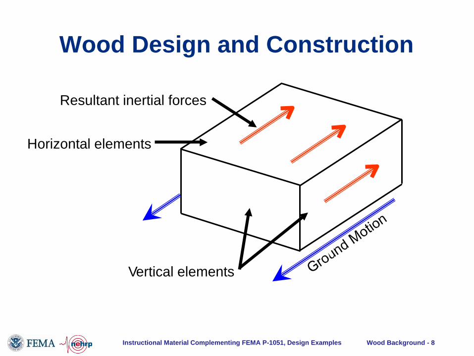
Instructional Material Complementing FEMA P-1051, Design Examples Wood Background - 8
Vertical elements
Resultant inertial forces
Horizontal elements
Wood Design and Construction

Instructional Material Complementing FEMA P-1051, Design Examples Wood Background - 9
ε
σ
Wood Design and Construction -
Seismic Response
3
2.5
2
1.5
1
0.5
0
-0.5
-1
-1.5
-2
-2.5
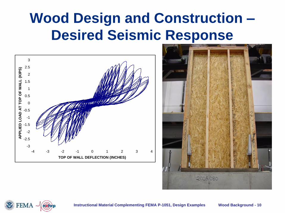
-3 -4 -3 -2 -1 0 1 2
TOP OF WALL DEFLECTION (INCHES)
3 4
AP
PL
IED
LO
AD
AT
TO
P O
F W
AL
L
(KIP
S)
Instructional Material Complementing FEMA P-1051, Design Examples Wood Background - 10
Wood Design and Construction –
Desired Seismic Response
3
2.5
2
1.5
1
0.5
0
-0.5
-1
-1.5
-2
-2.5
-3
-4 -3 -2 -1 0 1 2
TOP OF WALL DEFLECTION (INCHES)
3 4
AP
PL
IED
LO
AD
AT
TO
P O
F W
AL
L (
KIP
S)

Instructional Material Complementing FEMA P-1051, Design Examples Wood Background - 11
Individual nail test
600
500
400
300
200
100
0
-100
-200
-300
-400
-500
-600
-0.6 -0.5 -0.4 -0.3 -0.2 -0.1 0 0.1 0.2 0.3 0.4 0.5 0.6
DEFLECTION (INCHES)
NA
IL S
HE
AR
(P
OU
ND
S)
Full-scale shear wall test
3
2.5
2
1.5
1
0.5
0
-0.5
-1
-1.5
-2
-2.5
-3
-4 -3 -2 -1 0 1 2
TOP OF WALL DEFLECTION (INCHES)
3 4
AP
PL
IED
LO
AD
AT
TO
P O
F W
AL
L (
KIP
S)
Wood Design and Construction

Instructional Material Complementing FEMA P-1051, Design Examples Wood Background - 12
ε
σ
Wood Design and Construction -
Less Desirable Response
Inertial
Force
Resisting
Force
Ledger
Failure

Instructional Material Complementing FEMA P-1051, Design Examples Wood Background - 13
Positive Wall Tie
Wood Design and Construction

Instructional Material Complementing FEMA P-1051, Design Examples Wood Background - 14
• ASCE 7-16
• AWC NDS, 2015 Edition – wood framing and connections
• AWC SDPWS, 2015 Edition – shears, diaphragms, and anchorage
Wood Design and Construction

Instructional Material Complementing FEMA P-1051, Design Examples Wood Background - 15
• Supports ASD and LRFD
• Framing and connections
– ASD: F’x = FxCDCyCz etc
– LRFD: F’x = FxKDxCyCz etc
• Shear walls and diaphragms
– vASD = vs / 2
– vLRFD = Dvs = 0.8vs
Wood Design and Construction
Instructional Material Complementing FEMA P-1051, Design Examples Wood Background - 16
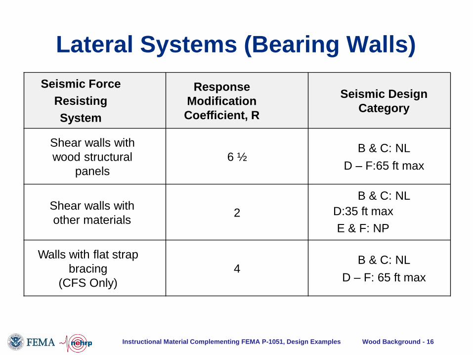
Seismic Force
Resisting
System
Response
Modification
Coefficient, R
Seismic Design
Category
Shear walls with
wood structural
panels
6 ½ B & C: NL
D – F:65 ft max
Shear walls with
other materials 2
B & C: NL
D:35 ft max
E & F: NP
Walls with flat strap
bracing
(CFS Only)
4 B & C: NL
D – F: 65 ft max
Lateral Systems (Bearing Walls)
Instructional Material Complementing FEMA P-1051, Design Examples Wood Background - 17
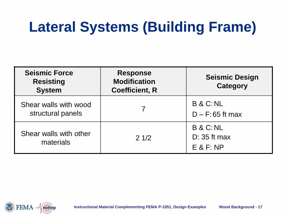
Lateral Systems (Building Frame)
Seismic Force
Resisting
System
Response
Modification
Coefficient, R
Seismic Design
Category
Shear walls with wood
structural panels 7
B & C: NL
D – F: 65 ft max
Shear walls with other
materials 2 1/2
B & C: NL
D: 35 ft max
E & F: NP

Instructional Material Complementing FEMA P-1051, Design Examples Wood Background - 18
Flexible vs Rigid Diaphragm – complexity:
• Neither rigid nor flexible diaphragm
assumptions truly represent the distribution of
seismic forces in a typical structure – both are
simplifications and the actual behavior is
“semi-rigid”
• Stiffness of the diaphragm relative to walls is
important in determining whether behavior is
more like rigid or more like flexible
Wood Design and Construction

Instructional Material Complementing FEMA P-1051, Design Examples Wood Background - 19
• ASCE 7 Sec. 12.3.1.1: Diaphragms constructed of
untopped steel deck or wood structural panels are permitted
to be idealized as flexible if any of the following conditions
exist:
a. In structures where vertical elements are steel braced
frames, steel and concrete composite braced frames, or
concrete, masonry or steel and concrete composite walls
b. In one- and two-family dwellings
c. In structures of light-frame construction where all of the
following conditions are met
1. Nonstructural topping not greater than 1-1/2 inch
2. Each line of vertical elements complies with drift limits
Diaphragms Idealized As Flexible

Instructional Material Complementing FEMA P-1051, Design Examples Wood Background - 20
• ASCE 7 Sec. 12.3.1.3:
“… the computed maximum in-plane deflection of the diaphragm under lateral
load , dMDD, is more than two times the average story drift of adjoining vertical
elements of the lateral force-resisting system of the associated story, DADVE,
under equivalent tributary lateral load.”
Diaphragms Calculated As Flexible
Instructional Material Complementing FEMA P-1051, Design Examples Wood Background - 21
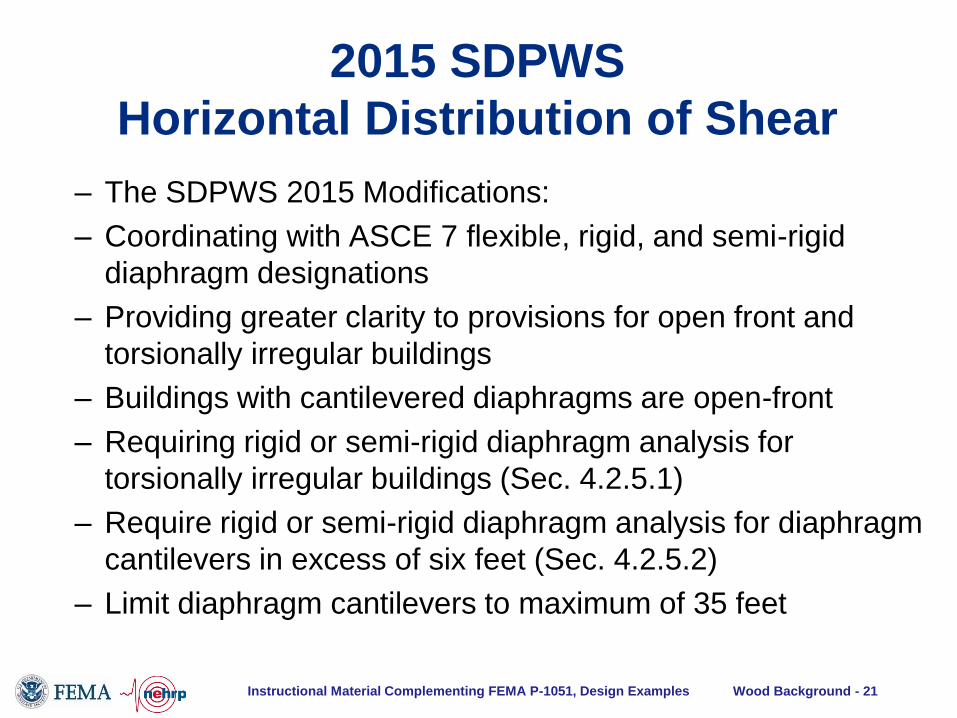
– The SDPWS 2015 Modifications:
– Coordinating with ASCE 7 flexible, rigid, and semi-rigid
diaphragm designations
– Providing greater clarity to provisions for open front and
torsionally irregular buildings
– Buildings with cantilevered diaphragms are open-front
– Requiring rigid or semi-rigid diaphragm analysis for
torsionally irregular buildings (Sec. 4.2.5.1)
– Require rigid or semi-rigid diaphragm analysis for diaphragm
cantilevers in excess of six feet (Sec. 4.2.5.2)
– Limit diaphragm cantilevers to maximum of 35 feet
2015 SDPWS
Horizontal Distribution of Shear

Instructional Material Complementing FEMA P-1051, Design Examples Wood Background - 22
• Provision of a complete load
path is essential to performance
of wood light-frame seismic
force-resisting systems
• Due to nature of wood
construction, this involves a
number of connections
• Will be discussed in detail for
shear walls and diaphragms
Complete Load Path

Instructional Material Complementing FEMA P-1051, Design Examples Wood Background - 23
Shearwalls

Instructional Material Complementing FEMA P-1051, Design Examples Wood Background - 24
Instructional Material Complementing FEMA P-751, Design Examples
Three types of shear walls:
Shear Walls

Instructional Material Complementing FEMA P-1051, Design Examples Wood Background - 25
Per AF&PA Sec. 4.3, design
provisions include
• Deflection determination
• Unit shear capacities
(shear wall tables)
• Aspect ratios
• Anchorage
• Construction
requirements
Shear Walls

Instructional Material Complementing FEMA P-1051, Design Examples Wood Background - 26
Shear wall table information
• Nominal unit shear capacities
• Tables are for DF-L or SP – need to adjust values if
framing with wood species with lower specific
gravities
Major divisions:
• Structural I vs. Rated Sheathing
• Panels applied directly to framing vs. panels
applied over gypsum wallboard
• Seismic and wind tabulated separately
• Unblocked edges allowed in some conditions
Shear Walls

Instructional Material Complementing FEMA P-1051, Design Examples Wood Background - 27
Aspect ratios
• Application varies by shear wall type
Shear Walls

Instructional Material Complementing FEMA P-1051, Design Examples Wood Background - 28
2015 SDPWS Sec. 4.3 – Force
distribution to shear walls in a line – 2005, 2008 SDPWS:
• Distribute seismic/
wind forces to provide
same deflection where
materials and
construction are same
– 2015 SDPWS:
• Where materials and
construction are same,
distribute seismic/ wind
forces proportional to
shear capacity, adjust
for slender piers

Instructional Material Complementing FEMA P-1051, Design Examples Wood Background - 29
2015 SDPWS Sec. 4.3 –
Shear walls with narrow piers
– Capacity Adjustment: Narrow
wall pier adjusted for aspect
ratio greater than 2:1:
• Wood structural panel:
1.25 – 0.125h/bs
• Fiberboard:
1.09 – 0.09h/bs
– Different deflection
adjustment made to narrow
pier when distributing force
within wall line

Instructional Material Complementing FEMA P-1051, Design Examples Wood Background - 30
2015 SDPWS Sec. 4.3 – Perforated
shear walls
– Length of wood structural
panel sheathing used to
obtain Co (in SLi) adjusted
for ratio greater than 2:1
narrow wall pier:
• 2h/bs

Instructional Material Complementing FEMA P-1051, Design Examples Wood Background - 31
Section & Elevation Plan
Typical apartment
partitions
Post & beam
lines
148'-0"
28'-0" 8'-0"
112" Lightweight concrete
over plywood deck on joists at 16" o.c.
148'-0"
Corridor walls
Stairs
56
'-0"
9'-
0"
30'-0" 13'-0" 26'-0" 30'-0" 15'-0" 26'-0"
Sheathed wall
Glazed wall
4'
9'
9'
9'
8'-0"
Doors
• 3-story apartment building
• Stick framed with plywood shear walls and diaphragms
• Seismic Design Category D
• ASCE 7 Sec. 12.14 Simplified Procedure
Design Example: Shear Walls

Instructional Material Complementing FEMA P-1051, Design Examples Wood Background - 32
.
•148'-0"
•56'-
0"
•25
'-0"
•25
'-0"
•A
•30'-0" •30'-0" •15'-0"
•30'-0" •15'-0"•30'-0"
•Solid interior
•wall
•Solid end
•wall
•Perforated
•exterior wall
•55 feet of net shear wall •length, each side of •corridor, distributed over
•length of building.
•56'-0" •84'-0"
• Interior shear wall, 25 feet long, solid
Design Example: Shear Walls
Instructional Material Complementing FEMA P-1051, Design Examples Wood Background - 33
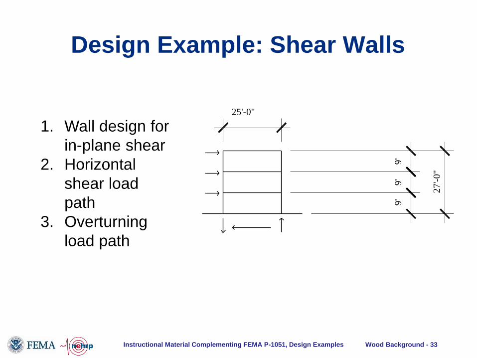
9'
9
'
9'
27
'-0
"
25'-0"
1. Wall design for
in-plane shear
2. Horizontal
shear load
path
3. Overturning
load path
Design Example: Shear Walls

Instructional Material Complementing FEMA P-1051, Design Examples Wood Background - 34
9'
9'
9'
Provide tie-down
anchor at each end
bolted to end post
at each level.
= 11.68 kips
25'-0"
= 7.50 kips
= 11.68 kips
Provide 58" anchorbolts at 1'-4" o.c.
W D
F3rd
Froof
F2nd
Seismic Force to Center 50% Each Wall(strength level) x0.50 x0.50
FROOF = 30.0 kips = 15.0 kips = 7.50 kips
F3RD = 46.7 kips = 23.35 kips = 11.68 kips
F2ND = 46.7 kips = 23.35 kips = 11.68 kips
Design Example: Shear Walls

Instructional Material Complementing FEMA P-1051, Design Examples Wood Background - 35
First floor design for shear:
• V = 7.5 + 11.68 + 11.68 = 30.86 kips
For 25 foot shear wall shown
• Unit Shear v1st = 30.86 kips/25 ft = 1.236 klf
• This is strength level demand
Design Example: Shear Walls

Instructional Material Complementing FEMA P-1051, Design Examples Wood Background - 36
Capacity From SDPWS Table 4.3A for blocked wood structural
panel shear walls
• 19/32 rated sheathing on Hem-Fir studs at 16” o.c.
• Nominal unit shear capacity vs = 1.740 klf
• F = 0.80 (SDPWS Sec. 4.3.3)
• Adjustment for stud species with S.G. = 0.43
= 1 – (0.5 – 0.43) = 0.93 (SDPWS Table 4.3A footnote)
• Adjusted capacity = (0.93)(0.8)(1.740) = 1.294 > 1.236 OK
• This shear wall requires 3x or stitched 2-2x framing
members at abutting panel edges to avoid framing splitting
during nail driving (SDPWS Sec. 4.3.7.1, Item 4)
• Design shear anchorage to the foundation
Design Example: Shear Walls
Instructional Material Complementing FEMA P-1051, Design Examples Wood Background - 37
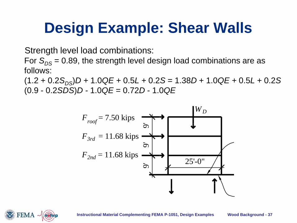
9'
9'
9'
Provide tie-down
anchor at each end
bolted to end post
at each level.
= 11.68 kips
25'-0"
= 7.50 kips
= 11.68 kips
Provide 58" anchorbolts at 1'-4" o.c.
W D
F3rd
Froof
F2nd
Strength level load combinations: For SDS = 0.89, the strength level design load combinations are as
follows:
(1.2 + 0.2SDS)D + 1.0QE + 0.5L + 0.2S = 1.38D + 1.0QE + 0.5L + 0.2S
(0.9 - 0.2SDS)D - 1.0QE = 0.72D - 1.0QE
Design Example: Shear Walls
Instructional Material Complementing FEMA P-1051, Design Examples Wood Background - 38
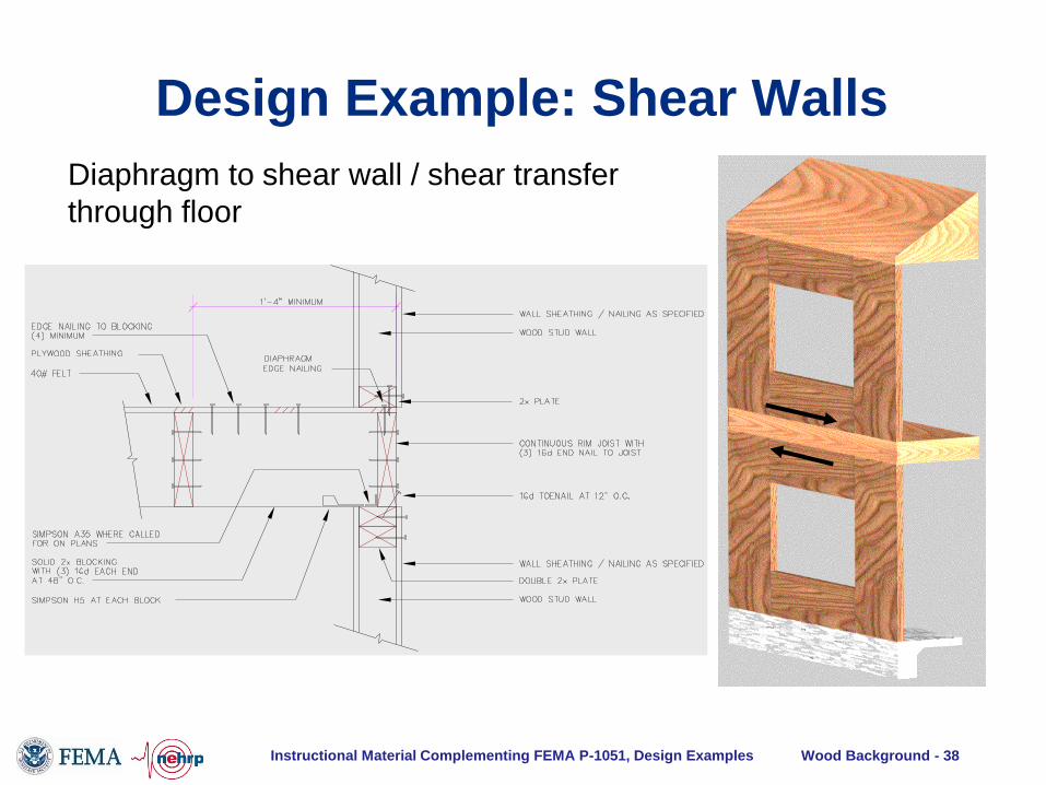
Diaphragm to shear wall / shear transfer
through floor
Design Example: Shear Walls

Instructional Material Complementing FEMA P-1051, Design Examples Wood Background - 39
Shear wall overturning / transfer
of vertical forces through floor
Design Example: Shear Walls
Instructional Material Complementing FEMA P-1051, Design Examples Wood Background - 40
Diaphragms

Instructional Material Complementing FEMA P-1051, Design Examples Wood Background - 41
Diaphragm
simplifying
assumptions:
-Sheathing resists
shear
-Chord resists
tension,
compression like
beam flange
-Boundary element
at every sheathing
edge
Diaphragms

Instructional Material Complementing FEMA P-1051, Design Examples Wood Background - 42
Continuous Panel Edge
Parallel to Load
Unblocked Edge
Continuous Panel Edge “Field” nailing
Supported Edge
Diaphragm Boundary
“Edge” nailing
Diaphragm Sheathing
Diaphragms

Instructional Material Complementing FEMA P-1051, Design Examples Wood Background - 43
Diaphragm
simplifying
assumptions:
-Collector resists
tension &
compression
- Continuity
assumption may
vary at interior
vertical element
Diaphragms

Instructional Material Complementing FEMA P-1051, Design Examples Wood Background - 44
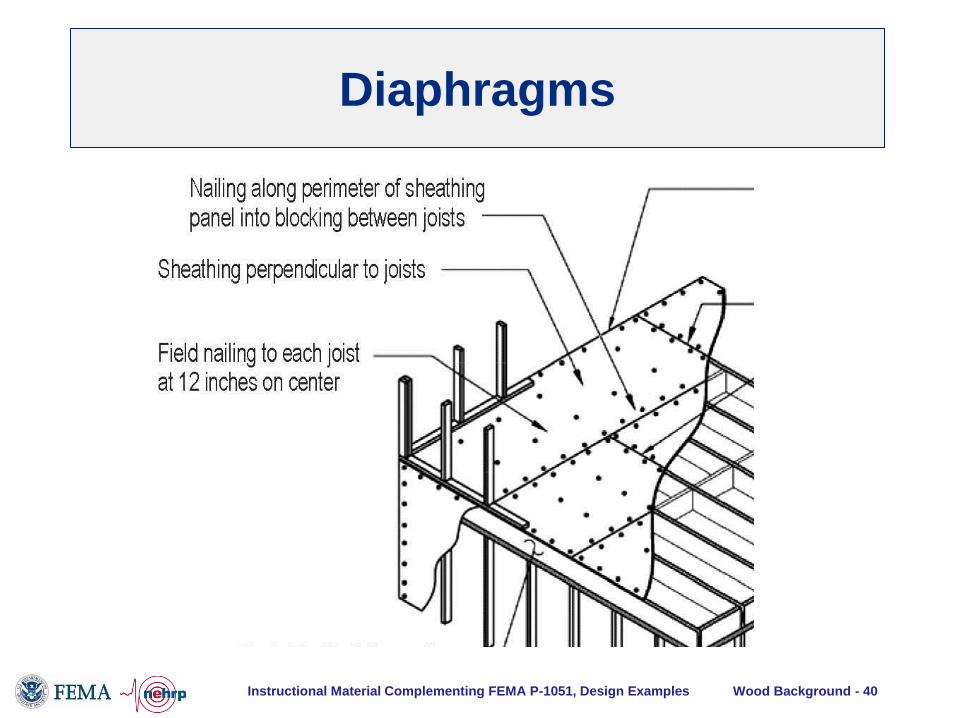
Diaphragm
sheathing:
Blocked
Diaphragms

Instructional Material Complementing FEMA P-1051, Design Examples Wood Background - 45
Diaphragm
sheathing:
Unblocked
Diaphragms
Instructional Material Complementing FEMA P-1051, Design Examples Wood Background - 46
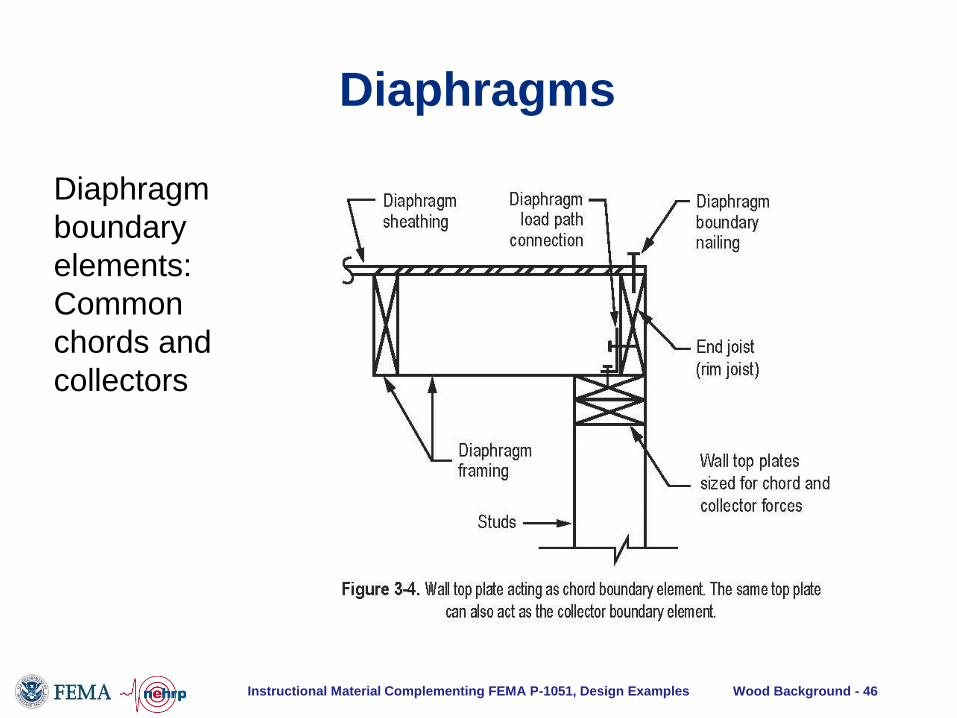
Diaphragm
boundary
elements:
Common
chords and
collectors
Diaphragms
Instructional Material Complementing FEMA P-1051, Design Examples Wood Background - 47
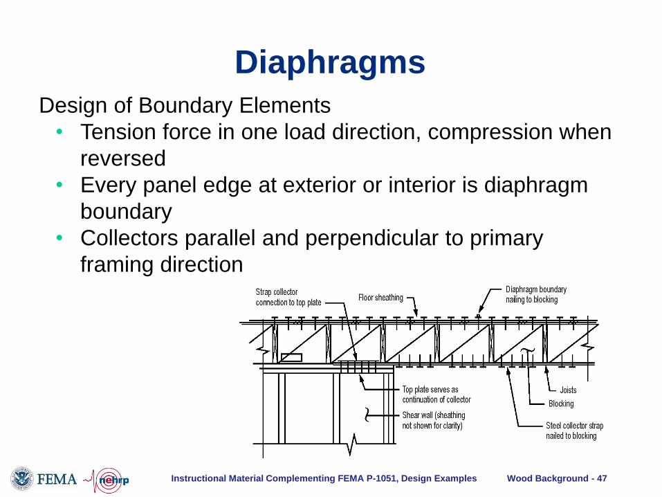
Design of Boundary Elements
• Tension force in one load direction, compression when
reversed
• Every panel edge at exterior or interior is diaphragm
boundary
• Collectors parallel and perpendicular to primary
framing direction
Diaphragms

Instructional Material Complementing FEMA P-1051, Design Examples Wood Background - 48
Diaphragm
boundary
elements:
Detailing at
diaphragm
openings
Diaphragms

Instructional Material Complementing FEMA P-1051, Design Examples Wood Background - 49
Diaphragm Seismic Design Forces
Diaphragm Seismic Design
Forces
Inertial forces
generated by the seismic
weight tributary to the
diaphragm
Instructional Material Complementing FEMA P-1051, Design Examples Wood Background - 50
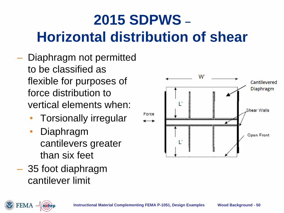
2015 SDPWS –
Horizontal distribution of shear
– Diaphragm not permitted
to be classified as
flexible for purposes of
force distribution to
vertical elements when:
• Torsionally irregular
• Diaphragm
cantilevers greater
than six feet
– 35 foot diaphragm
cantilever limit
Instructional Material Complementing FEMA P-1051, Design Examples Wood Background - 51
Diaphragm Design Forces – NEW ALTERNATIVE – SEE CHAPTER 6 OF
NEHRP DESIGN EXAMPLES (Sec. 12.10.3)
• Seismic forces in the diaphragm are influenced by both the type of
vertical elements and the type of diaphragm, but the Basic Method
(Section 12.10.1.1) only recognizes the vertical elements as an
influence
• Section 12.10.3 takes into account the displacement capacity of the
specific diaphragm type used
• Diaphragm forces start from near-elastic level, and are divided by Rs
diaphragm design force reduction factor, specific to the diaphragm type
ASCE 7-16 - Seismic Force –
Alternate Provisions

Instructional Material Complementing FEMA P-1051, Design Examples Wood Background - 52
Diaphragm Seismic Design Forces
Diaphragm Seismic Design
Forces
Inertial forces
Transfer forces
generated by
discontinued vertical
elements or
generated by changes in
stiffness of vertical
elements over height of
structure
Instructional Material Complementing FEMA P-1051, Design Examples Wood Background - 53
Diaphragm Seismic Design Forces
Diaphragm Seismic Design Forces
Diaphragm design must be consistent with
diaphragm classification – rigid, semi-rigid, flexible
Sheathing
Design for in-plane shear in accordance with
SDPWS
Boundary members and connections
Design for tension and compression in accordance
with NDS
No overstrength forces for chords
No overstrength forces for collectors for structures
or portions thereof braced entirely by light-frame
shear walls (ASCE 7-10, Sec. 12.10.2)
Instructional Material Complementing FEMA P-1051, Design Examples Wood Background - 54
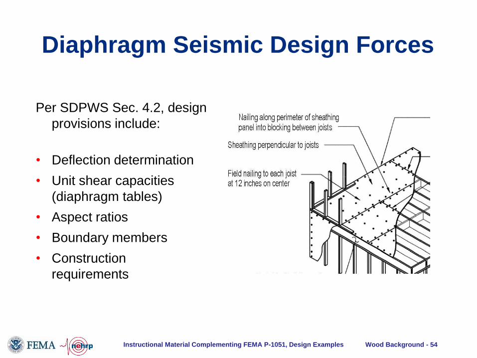
Per SDPWS Sec. 4.2, design
provisions include:
• Deflection determination
• Unit shear capacities
(diaphragm tables)
• Aspect ratios
• Boundary members
• Construction
requirements
Diaphragm Seismic Design Forces
Instructional Material Complementing FEMA P-1051, Design Examples Wood Background - 55
148'-0"
56
'-0
"
25
'-0
"2
5'-
0"
30'-0"30'-0"15'-0"
30'-0"30'-0"15'-0"
Solid
interior
wall
Solid
end
wall
Some corridor
walls are used
as shear walls
Perforated
exterior
wall56'-0" 84'-0"
SPAN = 88 ft
W = 0.202 klf
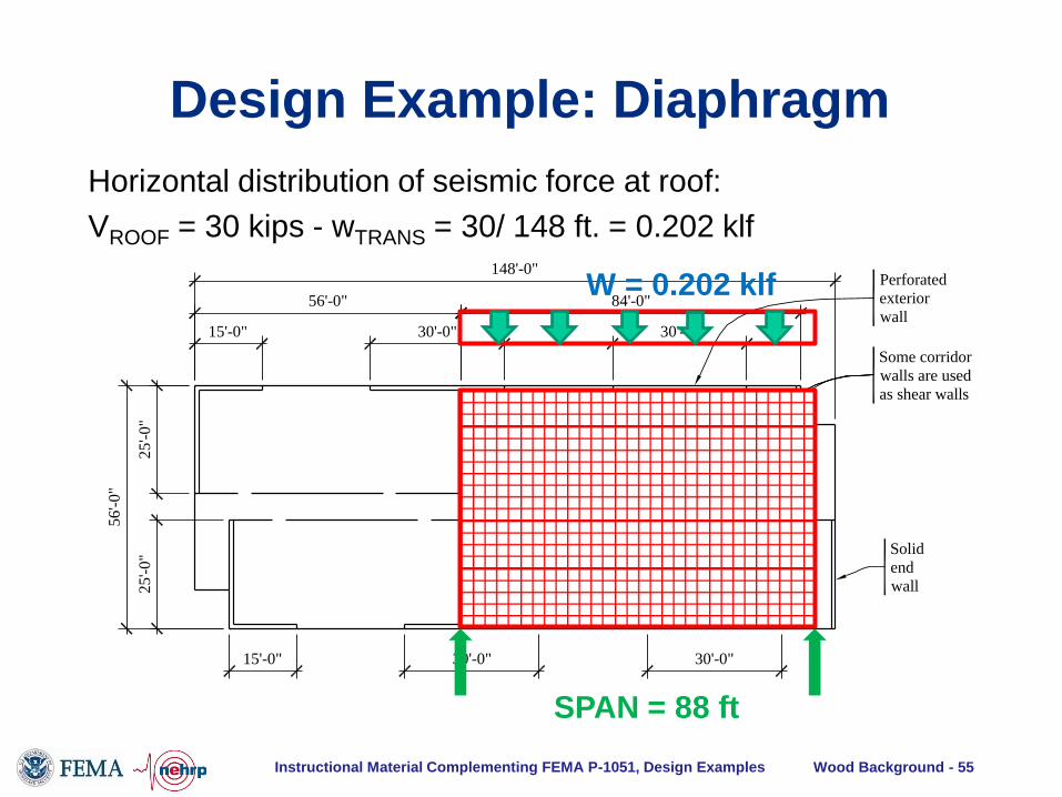
Horizontal distribution of seismic force at roof:
VROOF = 30 kips - wTRANS = 30/ 148 ft. = 0.202 klf
Design Example: Diaphragm
Instructional Material Complementing FEMA P-1051, Design Examples Wood Background - 56
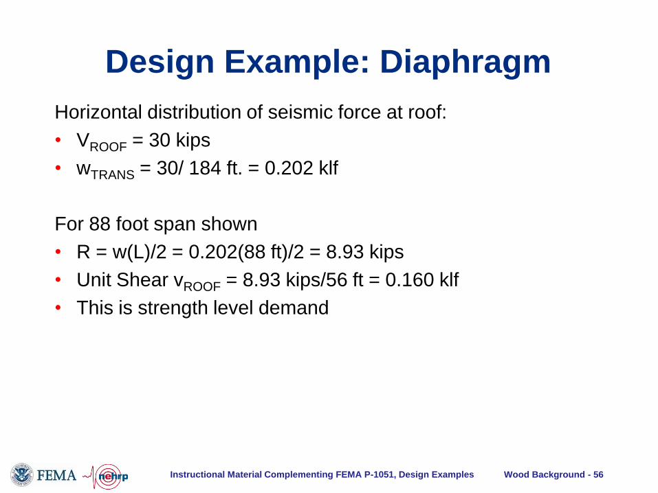
Horizontal distribution of seismic force at roof:
• VROOF = 30 kips
• wTRANS = 30/ 184 ft. = 0.202 klf
For 88 foot span shown
• R = w(L)/2 = 0.202(88 ft)/2 = 8.93 kips
• Unit Shear vROOF = 8.93 kips/56 ft = 0.160 klf
• This is strength level demand
Design Example: Diaphragm

Instructional Material Complementing FEMA P-1051, Design Examples Wood Background - 57
For 88 foot span shown
• Unit Shear vROOF = 8.93 kips/56 ft = 0.160 klf
• This is strength level demand
Capacity From SDPWS Table 4.2C for unblocked wood
structural panel diaphragms
• Construct as load case 1 for transverse load direction,
since this is longest span
• 15/32 rated sheathing on 2x DF-L framing
• Nominal unit shear capacity vs = 0.480 klf
• F = 0.80 (SDPWS Sec. 4.2.3)
• Adjusted capacity = (0.8)(0480) = 0.384 > 0.160 OK
Design Example: Diaphragm

Instructional Material Complementing FEMA P-1051, Design Examples Wood Background - 58
Anchorage of Concrete and
Masonry Walls

Instructional Material Complementing FEMA P-1051, Design Examples Wood Background - 59
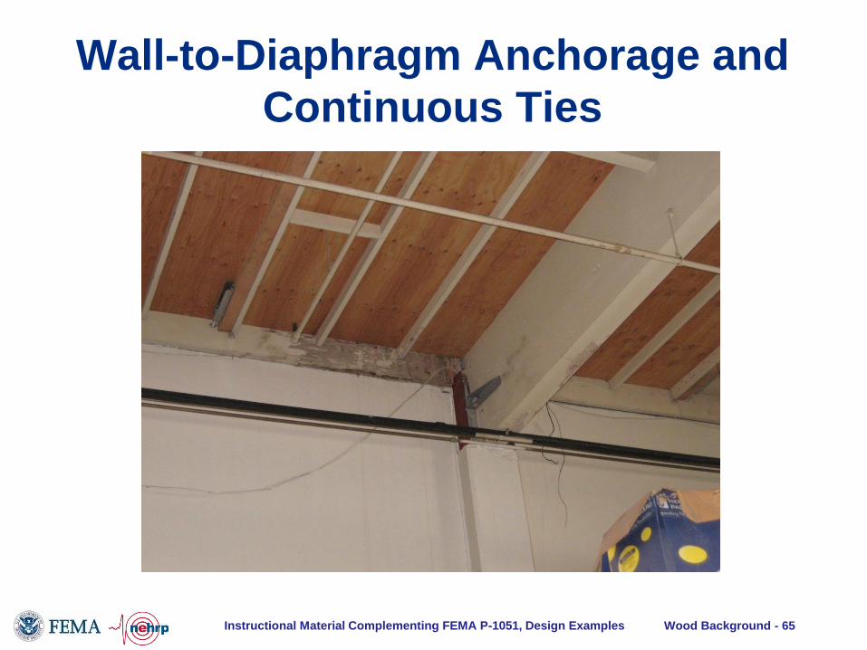
Wall-to-Diaphragm Anchorage and
Continuous Ties

Instructional Material Complementing FEMA P-1051, Design Examples Wood Background - 60
Inertial
Force
Resisting
Force
Ledger
Failure
• Tension
perpendicular to
grain results in
brittle failures at
low loads
• Does not
provide a
reliable load
path
Wall-to-Diaphragm Anchorage and
Continuous Ties

Instructional Material Complementing FEMA P-1051, Design Examples Wood Background - 61
Wall-to-
Diaphragm
Anchorage and
Continuous Ties

Instructional Material Complementing FEMA P-1051, Design Examples Wood Background - 62
• Design Considerations
– Substantial experience
w/ earthquake
performance
– Numerous studies on
seismic demand on these
connections
– Even more recent
construction may required
retrofit
– Objective is tie between
exterior walls
Wall-to-Diaphragm Anchorage and
Continuous Ties

Instructional Material Complementing FEMA P-1051, Design Examples Wood Background - 63
For walls anchored to flexible diaphragms, wall anchorage
force per ASCE 7-05 Sec. 12.11.2.1 and Eq. 12.11-1 is:
Fp = 0.4SDSkaIeWp
Where
ka = 1.0 + Lf/100 <= 2.0
Lf = diaphragm span = 200 ft
Ka = 1.0 + 200/100 = 3.0, use 2.0 max
Wall-to-Diaphragm Anchorage and
Continuous Ties

Instructional Material Complementing FEMA P-1051, Design Examples Wood Background - 64
Wall-to-Diaphragm Anchorage and
Continuous Ties Fp = 0.4SDSkaIeWp
Where
ka = 2.0
SDS = 1.43
Ie = 1.0
Transverse walls:
Wp= 65 psf(16ft)= 1.04 klf
Fp = 0.4(1.43)(2.0)(1.0)1.04 = 1.19 klf
Anchors at 4 ft = 1.19 (4.0)= 4.76 kips
Instructional Material Complementing FEMA P-1051, Design Examples Wood Background - 65
Wall-to-Diaphragm Anchorage and
Continuous Ties

Instructional Material Complementing FEMA P-1051, Design Examples Wood Background - 66
Wall-to-Diaphragm Anchorage and
Continuous Ties

Instructional Material Complementing FEMA P-1051, Design Examples Wood Background - 67
The subdiaphragm concept:
• Cannot run tension ties at 4 ft on center across entire
length of building, so develop into subdiaphragm
• Design subdiaphragm for anchorage force level
• Subdiaphragm reaction goes to major beam line
• Design continuous tie connections across major
beam lines for anchorage force level
Wall-to-Diaphragm Anchorage and
Continuous Ties

Instructional Material Complementing FEMA P-1051, Design Examples Wood Background - 68
The subdiaphragm concept:
5 b
ays
at 2
0'-
0"
= 1
00'-
0"
5 bays at 40'-0" = 200'-0"
8" concretemasonry wall
Typical glue-lam
roof beam
Plywood roof
sheathing
Open
12" concrete
masory wall
Wall anchorage to
subdiaphragm at 4 ft.
Subdiaphragm
approx. 20 ft. x 20 ft.
Glulam beams and
connections act as
continuous ties
Wall-to-Diaphragm Anchorage and
Continuous Ties

Instructional Material Complementing FEMA P-1051, Design Examples Wood Background - 69
Wall-to-Diaphragm Anchorage and
Continuous Ties
Instructional Material Complementing FEMA P-1051, Design Examples Wood Background - 70
Important items for wall anchorage of concrete and masonry
walls SDC C and up (Section 12.11.2.2):
• Continuous ties required between diaphragm chords
• Subdiaphragms permitted as part of continuous tie system provided subdiaphragm aspect ratio <=2.5
• Wall anchor forces required through the entire continuous
tie system
• Forces multiplied by 1.4 for steel elements of anchorage
• Diaphragm wood structural panel sheathing not permitted to be loaded in tension to provide continuous tie
• Embedded tension straps to be wrapped around or anchored to wall reinforcing
Wall-to-Diaphragm Anchorage and
Continuous Ties

Instructional Material Complementing FEMA P-1051, Design Examples Wood Background - 71
Questions?

Instructional Material Complementing FEMA P-1051, Design Examples Wood Background - 72
• NOTICE: Any opinions, findings, conclusions, or recommendations
expressed in this publication do not necessarily reflect the views of the
Federal Emergency Management Agency. Additionally, neither FEMA
nor any of its employees make any warranty, expressed or implied, nor
assume any legal liability or responsibility for the accuracy,
completeness, or usefulness of any information, product or process
included in this publication.
• The opinions expressed herein regarding the requirements of the
NEHRP Recommended Seismic Provisions, the referenced standards,
and the building codes are not to be used for design purposes. Rather
the user should consult the jurisdiction’s building official who has the
authority to render interpretation of the code.
• Any modifications made to the file represent the presenters' opinion
only.
DISCLAIMER