introduction to the stepper stall detector module€¦ · · 2016-10-31semiconductor’s stepper...
TRANSCRIPT

Freescale SemiconductorApplication Note
Document Number: AN3330Rev. 1, 11/2010
Contents
Introduction . . . . . . . . . . . . . . . . . . . . . . . . . . . . . . . . . . . 1SSD Applications. . . . . . . . . . . . . . . . . . . . . . . . . . . . . . . 2SSD Connections . . . . . . . . . . . . . . . . . . . . . . . . . . . . . . 3SSD Features . . . . . . . . . . . . . . . . . . . . . . . . . . . . . . . . . 3Stepper Motor Components and Mechanics . . . . . . . . . . 4Channel Signals for Driving a Stepper Motor . . . . . . . . . 5Back EMF . . . . . . . . . . . . . . . . . . . . . . . . . . . . . . . . . . . . 7Integration . . . . . . . . . . . . . . . . . . . . . . . . . . . . . . . . . . . . 8Offset Cancellation . . . . . . . . . . . . . . . . . . . . . . . . . . . . . 8
0 Blanking. . . . . . . . . . . . . . . . . . . . . . . . . . . . . . . . . . . . . 101 The SSD Accumulator . . . . . . . . . . . . . . . . . . . . . . . . . . 122 Setting the Stall Level . . . . . . . . . . . . . . . . . . . . . . . . . . 133 Flowchart of Integration and Stall Detection . . . . . . . . . 134 Summary . . . . . . . . . . . . . . . . . . . . . . . . . . . . . . . . . . . . 165 C Programming Example . . . . . . . . . . . . . . . . . . . . . . . 176 Application Tips . . . . . . . . . . . . . . . . . . . . . . . . . . . . . . . 21
Introduction to the Stepper Stall Detector Moduleby: Matthew Grant
Microcontroller Division, 16-Bit Applications
1 Introduction This application note introduces Freescale Semiconductor’s stepper stall detector (SSD) module. The SSD’s primary function is to detect a stalled or impeded step in a stepper motor attempting to spin. This application note supplements the SSD block guide or reference manual chapter associated with the microcontroller(s) containing this module. This document discusses target applications, SSD setup, SSD features, stepper motor components, full step-signal sequences, back EMF, integration, offset cancellation, the accumulator, and stall level; a flowchart is shown to assist with basic code development. Currently the HCS12HZ, HCS12XHZ, and MC9S12XHY family of microcontrollers have this module.
1234567891111111
© Freescale Semiconductor, Inc.,2010. All rights reserved.

SSD Applications
This document discusses how the module should be connected and used as well as how back EMF forms and integrates to give information about a stepper motor’s net rotation. For complex systems with stall detection capabilities, this module may be a replacement and reduce system cost and complexity by eliminating extra components. After users are familiar with the SSD module, they can use it effectively in their own applications.
2 SSD ApplicationsThe SSD module may be used in many applications involving stepper motors. This module is suited for automotive cluster applications. In these applications, the rotor of the stepper motor is fitted with a pointer used to illustrate gauge readings. At times the position of the gauge pointer should be zeroed out to maintain an accurate reference. The module’s stall-detection capabilities allow the microcontroller a means of detecting when the pointer has reached zero (see Figure 1 and Figure 2).
Figure 1. Typical Gauge Pointer in Use
Introduction to the Stepper Stall Detector Module, Rev. 1
Freescale Semiconductor2

SSD Connections
Figure 2. Gauge Pointer at Zero
3 SSD ConnectionsSSD module users can use and connect the module specific to the intended application. The module’s MCU pins can be connected directly to the motor contacts of the stepper motor, if the MCU voltage and current drive are compatible with the selected stepper motor. The SSD module’s two cosine pins should be connected to the motor contacts of one coil; the two sine pins should be connected to the other coil. These pins do not directly generate sinusoidal voltages or currents, but output logical voltages of VDDM and VSSM, which are the source voltages for the SSD module.
Figure 3. SSD Connections
As the gauge returns to zero, theSSD module detects the pointer collision with the stopper.
stopperstopper
steps
pointer
motor housing
SSD pins connected to motor contacts. S12(X)HZ
family MCU
example programming board
motor contacts
…S1 S2
Sn
CosM CosP
SinM SinP
CosM
CosPSinM
SinP
steps
pointer
motor housing
SSD pins connected to motor contacts. S12(X)HZ
family MCU
example programming board
motor contacts
…S1 S2
Sn
CosM CosP
SinM SinP
CosM
CosPSinM
SinP
Introduction to the Stepper Stall Detector Module, Rev. 1
Freescale Semiconductor 3
SSD Features
4 SSD FeaturesSeveral SSD module features give users flexibility:
• The polarity bit in the SSD module can be used to switch the pins routed to the integration circuitry. Changing this bit changes the polarity of the integration result from positive to negative, and vice versa.
• Prescaler divides of the MCU bus clock of 64 or 512 can be used for the SSD modulus counter frequency.
• The prescaler bit (PRE) allows users to adjust the sample rate of the accumulator. Adjusting this can affect the accuracy of the integration result. The SSD block guide recommends sample frequencies between 500 kHz and 2 MHz.
• The accumulator overflow bit can indicate an overflow of the accumulator register.
• The offset cancellation controls internal accumulation error.
The SSD module is unique because it can use four pins to drive a small stepper motor with full steps but can also use two of those pins simultaneously during integration to detect the induced voltage created on the non-driven motor coil. This induced voltage, or back EMF, can be integrated over time to yield a cumulative value that can indicate motor rotation, or motor stall state.
5 Stepper Motor Components and MechanicsStepper motors come in a variety of different sizes and shapes, and some of their components and internal arrangements may vary. The SSD module was designed to work primarily with small, permanent magnet stepper motors. These motors may weigh a few ounces and can sink current on the order of tens of milliamps. Some stepper motors have four contact pins, two for each coil, where a signal can be applied to the motor to induce rotation of the rotor shaft. Individual signals can be applied to each contact pin (such as CosP, CosM, SinP, and SinM from the MCU pins), but the effective signal created across one entire coil is most important (such as SIGNAL A or B, see Figure 4). The effective signals applied to both coils are important because the sequence of these signals must work together in a fashion that produces rotation. Uncoordinated or misaligned signals will likely produce ineffective vibration or random rotation. Figure 4 shows some of the internal components of this type of stepper motor.
Introduction to the Stepper Stall Detector Module, Rev. 1
Freescale Semiconductor4

Stepper Motor Components and Mechanics
Figure 4. Permanent Magnet Stepper Motor
How these components produce rotation:
1. An effective voltage (signal) is applied across coil A, which causes current to flow through the coil winding (inductor).
2. As this change in electrical current occurs, a magnetic field develops within the coil (see Figure 4). The metallic core, which passes through the coil windings, channels the magnetic field toward the permanent magnet.
3. If the magnetic field from the coil and the magnetic field from the disk are not aligned North to South, the magnetic disk rotates. Because opposite magnetic fields attract and like fields repel each other, this rotation continues until the magnetic fields of the disk have aligned themselves with the opposite pair of fields from the coil. After the disk has rotated into the new position, it settles and stops moving.
NOTETo keep the disk rotating, the magnetic field from both coils must be changed periodically in a sequence with alternating magnetic fields that keep the magnetic disk in an unstable state and rotating in a very specific direction. This implies the effective voltage across the coils must be changed periodically.
CosP
CosM
SinP SinM
Introduction to the Stepper Stall Detector Module, Rev. 1
Freescale Semiconductor 5
Channel Signals for Driving a Stepper Motor
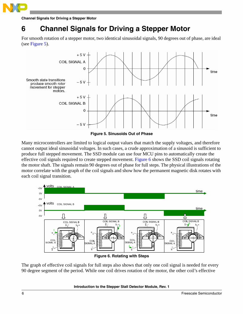
6 Channel Signals for Driving a Stepper MotorFor smooth rotation of a stepper motor, two identical sinusoidal signals, 90degreesout of phase, are ideal (see Figure 5).
Figure 5. Sinusoids Out of Phase
Many microcontrollers are limited to logical output values that match the supply voltages, and therefore cannot output ideal sinusoidal voltages. In such cases, a crude approximation of a sinusoid is sufficient to produce full stepped movement. The SSD module can use four MCU pins to automatically create the effective coil signals required to create stepped movement. Figure 6 shows the SSD coil signals rotating the motor shaft. The signals remain 90 degrees out of phase for full steps. The physical illustrations of the motor correlate with the graph of the coil signals and show how the permanent magnetic disk rotates with each coil signal transition.
Figure 6. Rotating with Steps
The graph of effective coil signals for full steps also shows that only one coil signal is needed for every 90 degree segment of the period. While one coil drives rotation of the motor, the other coil’s effective
+5V
0V
-5V
+5V
0V
-5V
COIL SIGNAL A
COIL SIGNAL B
time
time
volts
volts
Introduction to the Stepper Stall Detector Module, Rev. 1
Freescale Semiconductor6

Back EMF
voltage is forced to zero. Figure 7 shows alternating segments between coils A and B where the effective signal does not contribute to the motor’s rotation. On these segments the SSD module has the ability to use the associated SSD pins as an accumulation tool.
Figure 7. Signal Zero Sections
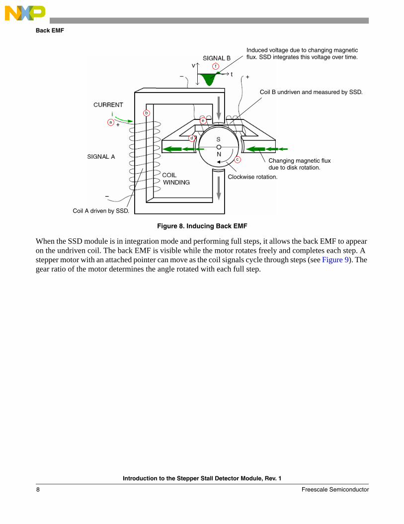
7 Back EMFWhen the SSD leaves a coil undriven while the other coil is driven, a voltage called the back electromotive force, or back EMF, can be observed across the terminals of the undriven coil. When a voltage (effectively a current) is applied to a coil (inductor), it can induce a magnetic field in the coil (see Figure 8). This principle is true of the reverse. When a change occurs in the magnetic field of a coil, this can induce a current (voltage) across that coil. This is where the SSD module can integrate the induced voltage and determine whether the magnetic disk has made any net rotation.
a) Voltage across coil A causes current to flow into coil A
b) Change in current produces magnetic field in the driven coil. The field is channeled toward the disk.
c) Disk rotates to oppositely align its magnetic fields with the fields produced by the driven coil.
d) Disk rotation causes change in the magnetic flux through the metallic core of the undriven coil.
e) Undriven coil fights against change in magnetic field. This induces a current in the undriven coil.
f) Due to change in the undriven coil current, a voltage can be measured across its terminals.
At these stages of the signal sequence, the effective signal applied to coil B is forced to zero and does not make a significant contribution to the motor’s rotation.
+5V
0V
-5V
+5V
0V
-5V
COIL SIGNAL A
COIL SIGNAL B
time
volts
volts
At these stages of the signal sequence, the effective signal applied to coil A is forced to zero and does not make a significant contribution to the motor’s rotation.
time
Introduction to the Stepper Stall Detector Module, Rev. 1
Freescale Semiconductor 7
Back EMF
Figure 8. Inducing Back EMF
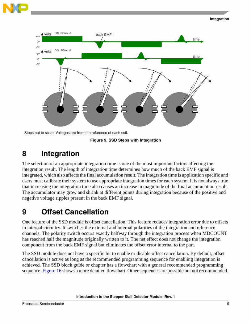
When the SSD module is in integration mode and performing full steps, it allows the back EMF to appear on the undriven coil. The back EMF is visible while the motor rotates freely and completes each step. A stepper motor with an attached pointer can move as the coil signals cycle through steps (see Figure 9). The gear ratio of the motor determines the angle rotated with each full step.
tv
a
b
c
d
e
f
tv
a
b
c
d
e
f
Induced voltage due to changing magneticflux. SSD integrates this voltage over time.
Coil B undriven and measured by SSD.
Changing magnetic flux
Clockwise rotation.
Coil A driven by SSD.
due to disk rotation.
Introduction to the Stepper Stall Detector Module, Rev. 1
Freescale Semiconductor8
Integration
Figure 9. SSD Steps with Integration
8 IntegrationThe selection of an appropriate integration time is one of the most important factors affecting the integration result. The length of integration time determines how much of the back EMF signal is integrated, which also affects the final accumulation result. The integration time is application specific and users must calibrate their system to use appropriate integration times for each system. It is not always true that increasing the integration time also causes an increase in magnitude of the final accumulation result. The accumulator may grow and shrink at different points during integration because of the positive and negative voltage ripples present in the back EMF signal.
9 Offset CancellationOne feature of the SSD module is offset cancellation. This feature reduces integration error due to offsets in internal circuitry. It switches the external and internal polarities of the integration and reference channels. The polarity switch occurs exactly halfway through the integration process when MDCOUNT has reached half the magnitude originally written to it. The net effect does not change the integration component from the back EMF signal but eliminates the offset error internal to the part.
The SSD module does not have a specific bit to enable or disable offset cancellation. By default, offset cancellation is active as long as the recommended programming sequence for enabling integration is achieved. The SSD block guide or chapter has a flowchart with a general recommended programming sequence. Figure 16 shows a more detailed flowchart. Other sequences are possible but not recommended.
+5V
0V
-5V
+5V
0V
-5V
COIL SIGNAL A
COIL SIGNAL B
time
volts
volts
time back EMF
Steps not to scale. Voltages are from the reference of each coil.
Introduction to the Stepper Stall Detector Module, Rev. 1
Freescale Semiconductor 9
Offset Cancellation
Recommended:
1. The modulus counter should be enabled (MCEN=1).
2. The modulus value should be written (MDCCNT=integration time)
3. The integration enabled (ITG=1).
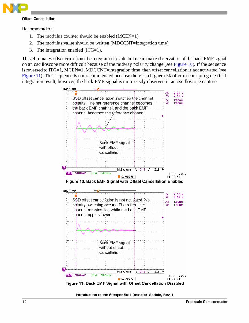
This eliminates offset error from the integration result, but it can make observation of the back EMF signal on an oscilloscope more difficult because of the midway polarity change (see Figure 10). If the sequence is reversed to ITG=1, MCEN=1, MDCCNT=integration time, then offset cancellation is not activated (see Figure 11). This sequence is not recommended because there is a higher risk of error corrupting the final integration result; however, the back EMF signal is more easily observed in an oscilloscope capture.
Figure 10. Back EMF Signal with Offset Cancellation Enabled
Figure 11. Back EMF Signal with Offset Cancellation Disabled
SSD offset cancellation switches the channel polarity. The flat reference channel becomes the back EMF channel, and the back EMF channel becomes the reference channel.
Back EMF signal with offset cancellation
SSD offset cancellation switches the channel polarity. The flat reference channel becomes the back EMF channel, and the back EMF channel becomes the reference channel.
Back EMF signal with offset cancellation
Back EMF signal without offset cancellation
SSD offset cancellation is not activated. No polarity switching occurs. The reference channel remains flat, while the back EMF channel ripples lower.
Back EMF signal without offset cancellation
SSD offset cancellation is not activated. No polarity switching occurs. The reference channel remains flat, while the back EMF channel ripples lower.
Introduction to the Stepper Stall Detector Module, Rev. 1
Freescale Semiconductor10

Blanking
10 BlankingOne of the primary components in a typical stepper motor is an inductor. Its significance in a motor comes from the ability to provide conversions back and forth between magnetic fields and electrical currents. One drawback of inductors is the inability to perform instantaneous changes in electrical current; therefore, fast internal switching of the SSD connections to the stepper motor can leave transient currents on a coil from the previous step. When performing integration, this effect is undesirable because it is possible these transients left over from switching can be seen as part of the back EMF and be integrated along with the actual back EMF created in the present step. This can distort the integration result, making it more difficult for software to determine whether a stall has occurred.
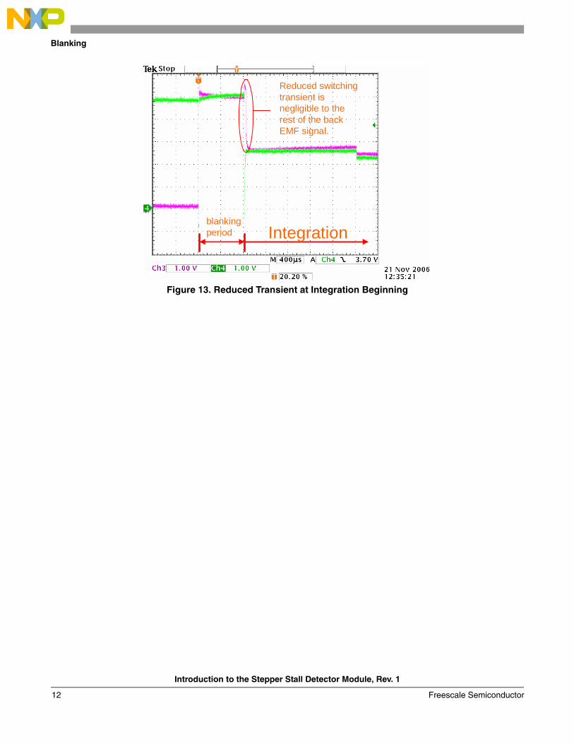
To combat this, the SSD module has a feature that recirculates the undriven coil current for a specified length of modulus counts. This allows most of the transient current to dissipate before the SSD module performs a step with integration and is known as blanking. Integration must be disabled during blanking. The length of blanking time depends on the system and can be determined by trials. The Figure 12 and Figure 13 show an example of the effects of blanking on the back EMF step signal.
Figure 12. Transient at Integration Beginning
Integration
Noticeable switching transient gets integrated with the rest of the back EMF signal.
Integration
Noticeable switching transient gets integrated with the rest of the back EMF signal.
Introduction to the Stepper Stall Detector Module, Rev. 1
Freescale Semiconductor 11
Blanking
Figure 13. Reduced Transient at Integration Beginning
Reduced switching transient is negligible to the rest of the back EMF signal.
blanking period Integration
Reduced switching transient is negligible to the rest of the back EMF signal.
blanking period Integration
Introduction to the Stepper Stall Detector Module, Rev. 1
Freescale Semiconductor12

The SSD Accumulator
11 The SSD AccumulatorThe module’s accumulator is a signed, 16-bit register where the integration results of the back EMF signal and any error is stored. The register values change many times during integration and can be read during integration for a snapshot value. Figure 14 shows several graphs correlating different characteristics of the SSD module register values and the back EMF signal by showing how they simultaneously behave and affect one another during integration.
Figure 14. Correlating the Counter, Back EMF, and Accumulations
t
t
t
V
Acc
umul
atio
nsM
odul
us R
egis
ter
Acc
umul
atio
ns
Vt
t
Acc
umul
atio
ns
t
b)
c)
d)
e)
f)
a)
a) Modulus down counter. The modulus register counts toward zero from its original value. When zero is reached, software should disable integration and read the accumulator to obtain the integrated step value.
b) Back EMF. The back EMF signal occurs across the non-driven coil during a full step with integration enabled.
c) Back EMF Accumulation. The accumulation result can grow and shrink due to the integration of positive and negative portions of the back EMF signal. An example accumulation result could be 1100.
d) This type of low voltage error can occur within the SSD module circuit during integration and can be positive or negative. When the SSD module is properly used, it can nearly eliminate this error by using an offset cancellation technique.
e) The offset error can also become integrated over time. Although this unwanted error can accumulate, the offset cancellation technique is activated midway through integration, and the accumulation error is reduced close to zero by the end of the integration process.
f) Both the back EMF (bottom) and offset error (top) are accumulated together. Some percentage of the value read during integration may be error, versus a read at the end of integration where the percentage of internal error should be nearly zero. The final result is 1100 despite the error involved during the integration process.
1100
1100
Introduction to the Stepper Stall Detector Module, Rev. 1
Freescale Semiconductor 13
Setting the Stall Level
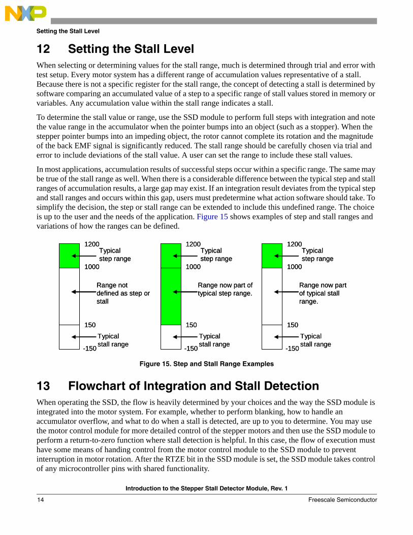
12 Setting the Stall LevelWhen selecting or determining values for the stall range, much is determined through trial and error with test setup. Every motor system has a different range of accumulation values representative of a stall. Because there is not a specific register for the stall range, the concept of detecting a stall is determined by software comparing an accumulated value of a step to a specific range of stall values stored in memory or variables. Any accumulation value within the stall range indicates a stall.
To determine the stall value or range, use the SSD module to perform full steps with integration and note the value range in the accumulator when the pointer bumps into an object (such as a stopper). When the stepper pointer bumps into an impeding object, the rotor cannot complete its rotation and the magnitude of the back EMF signal is significantly reduced. The stall range should be carefully chosen via trial and error to include deviations of the stall value. A user can set the range to include these stall values.
In most applications, accumulation results of successful steps occur within a specific range. The same may be true of the stall range as well. When there is a considerable difference between the typical step and stall ranges of accumulation results, a large gap may exist. If an integration result deviates from the typical step and stall ranges and occurs within this gap, users must predetermine what action software should take. To simplify the decision, the step or stall range can be extended to include this undefined range. The choice is up to the user and the needs of the application. Figure 15 shows examples of step and stall ranges and variations of how the ranges can be defined.
Figure 15. Step and Stall Range Examples
13 Flowchart of Integration and Stall DetectionWhen operating the SSD, the flow is heavily determined by your choices and the way the SSD module is integrated into the motor system. For example, whether to perform blanking, how to handle an accumulator overflow, and what to do when a stall is detected, are up to you to determine. You may use the motor control module for more detailed control of the stepper motors and then use the SSD module to perform a return-to-zero function where stall detection is helpful. In this case, the flow of execution must have some means of handing control from the motor control module to the SSD module to prevent interruption in motor rotation. After the RTZE bit in the SSD module is set, the SSD module takes control of any microcontroller pins with shared functionality.
1000
1200
150
-150
Typical stall range
Typical step range
Range not defined as step or stall
1000
1200
150
-150
Typical stall range
Typical step range
Range now part of typical step range.
1000
1200
150
-150
Typical stall range
Typical step range
Range now part of typical stall range.
1000
1200
150
-150
Typical stall range
Typical step range
Range not defined as step or stall
1000
1200
150
-150
Typical stall range
Typical step range
Range now part of typical step range.
1000
1200
150
-150
Typical stall range
Typical step range
Range now part of typical stall range.
Introduction to the Stepper Stall Detector Module, Rev. 1
Freescale Semiconductor14

Flowchart of Integration and Stall Detection
Figure 16 and Figure 17 show how the flow of execution might occur in a simple system. Figure 16 illustrates an example flow where no interrupts are used. In this case, many CPU cycles may be wasted in support of the SSD module. This flow is simple, but provides less efficient use of the CPU’s time. Refer to Section 15, “C Programming Example,” for example code following the general flow of Figure 16. The code can also be found in AN3330SW on the Freescale website.
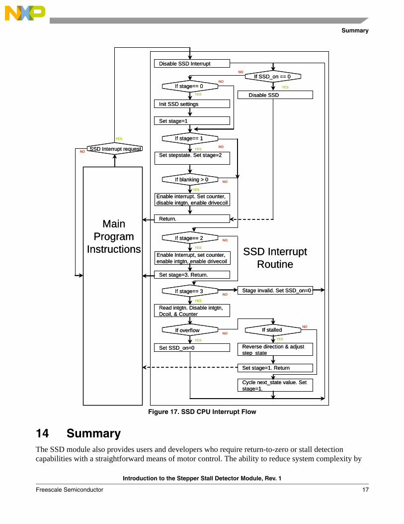
Figure 17 shows how CPU interrupts are used to drive the SSD module. This method of using interrupts to control the SSD module is more involved, but allows the service routine to entirely manage the SSD module. This provides more efficient use of CPU cycles and allow multiple interrupts to control multiple SSD modules. During a single step with integration, there are several times when the SSD module needs to be serviced. Because of this, the SSD service routine instructions are partitioned into stages. Each time the SSD interrupt is requested, the routine proceeds to the appropriate stage and performs the associated instructions. When complete, the routine returns control of the CPU to the general program. The code can also be found in AN3330SW.
Introduction to the Stepper Stall Detector Module, Rev. 1
Freescale Semiconductor 15
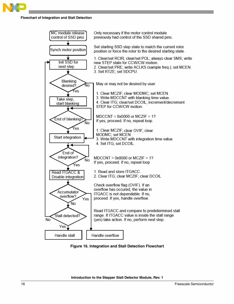
Flowchart of Integration and Stall Detection
Figure 16. Integration and Stall Detection Flowchart
Introduction to the Stepper Stall Detector Module, Rev. 1
Freescale Semiconductor16
Summary
Figure 17. SSD CPU Interrupt Flow
14 SummaryThe SSD module also provides users and developers who require return-to-zero or stall detection capabilities with a straightforward means of motor control. The ability to reduce system complexity by
If stage== 0
Init SSD settings
Set stage=1
If stage== 1
Return.
If stage== 2
Read intgtn. Disable intgtn, Dcoil, & Counter
If overflow
Disable SSD Interrupt
Set SSD_on=0
If stalled
Reverse direction & adjust step_state
Main Program
Instructions
SSD Interrupt request
Cycle next_state value. Set stage=1.
YES
YES
YES
YES
NO
NO
NO
NO
SSD Interrupt Routine
YES
NO
If SSD_on == 0NO
Disable SSD
YES
If blanking > 0
YES
NO
Enable interrupt. Set counter, disable intgtn, enable drivecoil
Enable Interrupt, set counter, enable intgtn, enable drivecoil
If stage== 3
YES
Set stage=3. Return.
Set stepstate. Set stage=2
NO
Set stage=1. Return
YES
Stage invalid. Set SSD_on=0NO
Introduction to the Stepper Stall Detector Module, Rev. 1
Freescale Semiconductor 17

C Programming Example
providing an alternative to external feedback circuitry improves ease of use, can reduce costs, and can simplify board design. The module is driven by software, providing users with total control over module operation and evaluation of accumulation results. Users looking for a sufficient alternative to more complex means of motor control may find the SSD a perfect fit.
15 C Programming ExampleThis program was written in C for Freescale’s MC9S12HZ256 microcontroller and compiled with the CodeWarrior for HCS12(X) compiler. There is also a version for the MC9S12XHZ512. In sections that follow the flowchart provided in Figure 16, the comments are labeled to match. All relevant code is contained in one file, main.c, shown below. CodeWarrior projects of this program and for an interrupt version for the MC9S12HZ256 and MC9S12XHZ512 may be downloaded from Freescale’s website. The software is contained in the AN3330SW and can easily be migrated to be used on the MC9S12XHY microcontroller.
To migrate to a different MCU follow these steps:
1. Using the CodeWarrior IDE remove current microcontroller derivative and add the desired derivative from {...CodeWarriorpath\lib\hc12c\include}
2. Using the CodeWarrior IDE, remove current microcontroller derivative and add the desired derivative from {…CodeWarior path \lib\hc12c\src }
3. If using interrupts make sure the interrupt vector is configured in the correct vector address. See the microcontroller reference manual.
/**##########################################################################**//** Author : Matthew Grant **//** Device : MC9S12HZ256 **//** DataSheet : 9S12HZ256DGV1/D V01.02 **//** Compiler : Code Warrior C compiler **//** Date : 12.29.2006 **//** Company : Freescale Semiconductor Inc. **//** Purpose : THIS IS A PROJECT, FOR FREESCALE'S SSD3 MODULE **//** ON THE MC9S12HZ256 MCU. THE FORMAT IS CONSISTENT WITH **//** PROJECTS GENERATED BY THE CODE WARRIOR WIZARD. THIS **//** PROJECT IS INTENDED TO BE A WORKING EXAMPLE UPON WHICH **//** USERS MAY GAIN FAMILIARITY WITH THE SSD MODULE. THIS **//** PROJECT IS PROVIDED AS IS WITH NO PROMISE OF SUPPORT, **//** AND FREESCALE MAKES NO GUARANTEE THIS PROJECT OR THE **//** FUNCTIONS INCLUDED WILL PERFORM AS DESIRED OR MEET THE **//** DEMANDS OF ANY REAL APPLICATION. **//** **//** Setup : THIS PROJECT IS WRITTEN TO WORK WITH A SMALL STEPPER **//** MOTOR CONNECTED TO THE SSD3 MODULE PINS ON THE 112-PIN **//** MC9S12HZ256. IT IS ASSUMED THE STEPPER MOTOR HAS A **//** POINTER ATTACHED TO THE SHAFT COMING OUT OF THE MOTOR. **//** WHEN THE PROJECT IS WORKING, THE USER SHOULD SEE THE **//** POINTER ROTATE IN ONE DIRECTION UNTIL IT BUMPS INTO AN **//** OBJECT. WHEN THE POINTER BUMPS INTO AN OBJECT, THE SSD **//** ACCUMULATOR SHOULD YIELD AN INTEGRATION RESULT WITH A **//** LOWER MAGNITUDE VALUE THAT IS BETWEEN THE STALL **//** MAGNITUDE AND ZERO. THE CODE MAY INTERPRET THIS AS A **//** STALL, AND REVERSE THE ROTATIONAL DIRECTION. THE PROCESS **//** REPEATS BY BEGINNING ANOTHER SEQUENCE OF STEPS UNTIL **/
Introduction to the Stepper Stall Detector Module, Rev. 1
Freescale Semiconductor18
C Programming Example
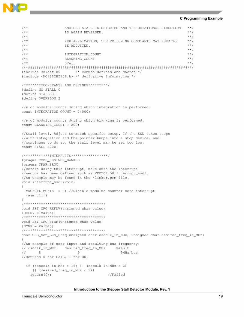
/** ANOTHER STALL IS DETECTED AND THE ROTATIONAL DIRECTION **//** IS AGAIN REVERSED. **//** **//** PER APPLICATION, THE FOLLOWING CONSTANTS MAY NEED TO **//** BE ADJUSTED. **//** **//** INTEGRATION_COUNT **//** BLANKING_COUNT **//** STALL **//**##########################################################################**/#include <hidef.h> /* common defines and macros */#include <MC9S12HZ256.h> /* derivative information */
/*********CONSTANTS AND DEFINES*********/#define NO_STALL 0#define STALLED 1#define OVERFLOW 2
//# of modulus counts during which integration is performed.const INTEGRATION_COUNT = 24000;
//# of modulus counts during which blanking is performed.const BLANKING_COUNT = 200;
//Stall level. Adjust to match specific setup. If the SSD takes steps//with integration and the pointer bumps into a stop device, and//continues to do so, the stall level may be set too low.const STALL =200;
/************INTERRUPTS*****************/#pragma CODE_SEG NON_BANKED#pragma TRAP_PROC//Before using this interrupt, make sure the interrupt//vector has been defined such as VECTOR 50 interrupt_ssd3.//An example may be found in the *linker.prm file.void interrupt_ssd3(void){ MDC3CTL_MCZIE = 0; //Disable modulus counter zero interrupt {asm cli;} }/*************************************/void SET_CRG_REFDV(unsigned char value){REFDV = value;}/*************************************/void SET_CRG_SYNR(unsigned char value){SYNR = value;}/*************************************/char CRG_Set_Bus_Freq(unsigned char oscclk_in_MHz, unsigned char desired_freq_in_MHz){//An example of user input and resulting bus frequency:// oscclk_in_MHz desired_freq_in_MHz Result// 8 9 9MHz bus//Returns 0 for FAIL, 1 for OK.
if ((oscclk_in_MHz > 16) || (oscclk_in_MHz < 2) || (desired_freq_in_MHz < 2)) return(0); //Failed
Introduction to the Stepper Stall Detector Module, Rev. 1
Freescale Semiconductor 19
C Programming Example
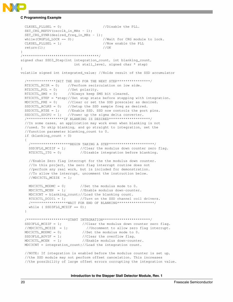
CLKSEL_PLLSEL = 0; //Disable the PLL. SET_CRG_REFDV(oscclk_in_MHz - 1); SET_CRG_SYNR(desired_freq_in_MHz - 1); while(CRGFLG_LOCK == 0); //Wait for CRG module to lock. CLKSEL_PLLSEL = 1; //Now enable the PLL return(1); //OK}/*************************************/signed char SSD3_Step(int integration_count, int blanking_count, int stall_level, signed char * step){volatile signed int integrated_value; //Holds result of the SSD accumulator
/**************INIT THE SDD FOR THE NEXT STEP****************/ RTZ3CTL_RCIR = 0; //Perform recirculation on low side. RTZ3CTL_POL = 0; //Set polarity. RTZ3CTL_SMS = 0; //Always keep SMS bit cleared.RTZ3CTL_STEP = *step;//Set step state before stepping with integration.
MDC3CTL_PRE = 0; //Clear or set the SSD prescaler as desired. SSD3CTL_ACLKS = 0; //Setup the SSD sample freq as desired. SSD3CTL_RTZE = 1; //Enable SSD. SSD now controls the port pins. SSD3CTL_SDCPU = 1; //Power up the sigma delta converter. /******************IF BLANKING IS DESIRED********************/ //In some cases, an application may work even when blanking is not //used. To skip blanking, and go straight to integration, set the //function parameter blanking_count to 0. if (blanking_count > 0) { /*******************BEGIN TAKING A STEP**********************/ SSD3FLG_MCZIF = 1; //Clear the modulus down counter zero flag. RTZ3CTL_ITG = 0; //Disable integration before blanking.
//Enable Zero flag interrupt for the the modulus down counter. //In this project, the zero flag interrupt routine does not //perform any real work, but is included for demonstration. //To allow the interrupt, uncomment the instruction below. //MDC3CTL_MCZIE = 1;
MDC3CTL_MODMC = 0; //Set the modulus mode to 0. MDC3CTL_MCEN = 1; //Enable modulus down-counter. MDC3CNT = blanking_count;//Load the blanking count. RTZ3CTL_DCOIL = 1; //Turn on the SSD channel coil drivers. /******************WAIT FOR END OF BLANKING******************/ while ( SSD3FLG_MCZIF == 0); } /********************START INTEGRATION***********************/ SSD3FLG_MCZIF = 1; //Clear the modulus down counter zero flag. //MDC3CTL_MCZIE = 1; //Uncomment to allow zero flag interrupt.MDC3CTL_MODMC = 0; //Set the modulus mode to 0.
SSD3FLG_AOVIF = 1; //Clear the overflow flag. MDC3CTL_MCEN = 1; //Enable modulus down-counter. MDC3CNT = integration_count;//Load the integration count.
//NOTE: If integration is enabled before the modulus counter is set up, //the SSD module may not perform offset cancelation. This increases //the possibility of large offset errors corrupting the integration value.
Introduction to the Stepper Stall Detector Module, Rev. 1
Freescale Semiconductor20

C Programming Example
//It is recommended to enable integration AFTER the modulus counter has //been setup and enabled.
RTZ3CTL_ITG = 1; //Begin integration. RTZ3CTL_DCOIL = 1;//Turn on the SSD channel coil drivers. /****************WAIT FOR END OF INTEGRATION*****************/ while ( SSD3FLG_MCZIF == 0); /*************READ ITGACC & DISABLE INTEGRATION**************/ integrated_value = ITG3ACC;//Immediately read and store the integration result.
RTZ3CTL_ITG = 0; //Turn off integration. SSD3FLG_MCZIF = 1; //Clear MCZIF flag for future interrupts. RTZ3CTL_DCOIL = 0; //Turn off the DCOIL. MDC0CTL_MCEN = 0; //Disable the modulus down-counter //Because the calling function will use the SSD again to take //another step, RTZE can be left enabled. If disabling is //desired, uncomment the line below. //SSD2CTL_RTZE = 0;
//NOW THAT INTEGRATION HAS COMPLETED, CHECK THE RESULT /***************CHECK FOR ACCUMULATOR OVERFLOW***************/if (SSD3FLG_AOVIF == 1)return(2);//Overflow detected.
/*********CHECK IF INTEGRATION VALUE IN STALL RANGE**********/if (((integrated_value <= stall_level) && (integrated_value >= 0))
|| ((integrated_value >= (-stall_level)) && (integrated_value <= 0))) return(1);//Stall detected.
elsereturn(0);//No stall detected.
}/*************************************/void main(void){signed char clockwise; //Indicates the motor's relative rotational directionsigned char result; //Holds the result of the stall detection functionsigned char * step; //Used to point to the step_state character variablesigned char step_state;//Keeps track of the 4 possible step states:0,1,2,3
EnableInterrupts;
//(OSCILLATOR VALUE IN MHz, DESIRED BUS IN MHz). Adjust as needed. if(! CRG_Set_Bus_Freq(8, 16)) for(;;); //If here, there may be some issue with MCU bus freq. //Initialize the step state to state 0. In a real application, //the initial position/starting state of the motor pointer may //not be perfectly aligned with state 0. Software may need to //take this into consideration if it is critical that the //initial step state be aligned with the physical state of //the motor. step_state = 0; //Arbitrarily initialized to 0.
step = &step_state; //Point the char * to the step_state variable. clockwise = 1; //Arbitrarily init rotational direction to 1. for(;;) {
Introduction to the Stepper Stall Detector Module, Rev. 1
Freescale Semiconductor 21
Application Tips
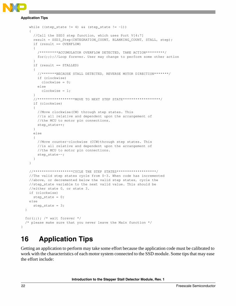
while ((step_state != 4) && (step_state != -1)) { //Call the SSD3 step function, which uses Port V[4:7] result = SSD3_Step(INTEGRATION_COUNT, BLANKING_COUNT, STALL, step); if (result == OVERFLOW) { /*********ACCUMULATOR OVERFLOW DETECTED, TAKE ACTION*********/ for(;;);//Loop forever. User may change to perform some other action } if (result == STALLED) { //*******BECAUSE STALL DETECTED, REVERSE MOTOR DIRECTION*******/ if (clockwise) clockwise = 0; else clockwise = 1; } //******************MOVE TO NEXT STEP STATE******************/ if (clockwise) { //Move clockwise(CW) through step states. This //is all relative and dependent upon the arrangement of //the MCU to motor pin connections. step_state++; } else { //Move counter-clockwise (CCW)through step states. This //is all relative and dependent upon the arrangement of //the MCU to motor pin connections. step_state--; } } //*******************CYCLE THE STEP STATES*******************/ //The valid step states cycle from 0-3. When code has incremented //above, or decremented below the valid step states, cycle the //step_state variable to the next valid value. This should be //either state 0, or state 3. if (clockwise) step_state = 0; else step_state = 3; } for(;;); /* wait forever */ /* please make sure that you never leave the Main function */}
16 Application TipsGetting an application to perform may take some effort because the application code must be calibrated to work with the characteristics of each motor system connected to the SSD module. Some tips that may ease the effort include:
Introduction to the Stepper Stall Detector Module, Rev. 1
Freescale Semiconductor22

Application Tips
• Motor selection: Some stepper motors work more smoothly with the SSD module than others. Motors with large step angles (measured at the pointer) may display more vibration than motors with smaller step angles. Generally, motors with small step angles usually produce smoother steps. Increasing the step rate can sometimes smooth the rotation and reduce any audible noise.
• Connections: Confirm that the pins from the SSD module are connected properly to the motor coils. Sometimes more than one arrangement can work as long as CosM and CosP are connected to the same coil, but SinM and SinP are connected to the other coil. If there is a problem, switch the connections between the signals to one coil. For example, switch SinM with SinP, but do not switch CosM and CosP.
• Step time: Select step times or rates within the recommended performance limits of the stepper motor. With respect to the SSD registers, assuming the bits ACKLS=0, and PRE=0, the following formula can help calculate the step time: 1 / (BusFreqInHz / (64 (8^PRE))) (# of counts)
An example case would be an 8 MHz bus with ACLKS=0, PRE=0, and the SSD performing integration for 12500 modulus counts. This yields a step time of approximately 0.100s.
1/(8000000/(64 (8^0))) (12500) = 0.100s
• Stall level: This is a critical setting that software uses to determine whether a particular step should be regarded as a successful step or as a stall. Using the program in this application note as an example, if the stall level is set too low, the software will consider a step successful even if the motor pointer has actually bumped into a stopper. This causes the SSD module to continue bumping into the stopper. If the stall level is set too high, the software may regard every step as a stalled step. This causes the software to constantly reverse the rotational direction and the motor pointer may remain fixed in one position. If any of these are observed, adjust the stall level in moderate amounts until the software successfully interprets the steps and the stalls.
• Motor load: The load placed on a motor can affect its step response and stall level. For example, a motor with a long pointer may work well with a particular step speed and stall level. If the attached pointer is changed to a short pointer, that same motor may work best at a different step speed with a different stall level. Generally the user must determine these settings through trials.
• Temperature: The successful step and stall ranges may change with variations in temperature. Experiment with the SSD and motor system to determine the expected range of step and stall variations across temperature and humidity and calibrate software to handle these variations. If the stall level is chosen on the boundary, using the motor for a short period of time may be enough to slightly change temperature and the response characteristics within the motor. This results in stalls that were previously detected properly going undetected. Select stall levels in the median of the determined stall range.
Introduction to the Stepper Stall Detector Module, Rev. 1
Freescale Semiconductor 23

Document Number: AN3330Rev. 111/2010
How to Reach Us:
Home Page:www.freescale.com
Web Support:http://www.freescale.com/support
USA/Europe or Locations Not Listed:Freescale Semiconductor, Inc.Technical Information Center, EL5162100 East Elliot RoadTempe, Arizona 85284+1-800-521-6274 or +1-480-768-2130www.freescale.com/support
Europe, Middle East, and Africa:Freescale Halbleiter Deutschland GmbHTechnical Information CenterSchatzbogen 781829 Muenchen, Germany+44 1296 380 456 (English)+46 8 52200080 (English)+49 89 92103 559 (German)+33 1 69 35 48 48 (French)www.freescale.com/support
Japan:Freescale Semiconductor Japan Ltd.HeadquartersARCO Tower 15F1-8-1, Shimo-Meguro, Meguro-ku,Tokyo 153-0064Japan0120 191014 or +81 3 5437 [email protected]
Asia/Pacific:Freescale Semiconductor China Ltd.Exchange Building 23FNo. 118 Jianguo RoadChaoyang DistrictBeijing 100022 China +86 10 5879 [email protected]
For Literature Requests Only:Freescale Semiconductor Literature Distribution Center1-800-441-2447 or 303-675-2140Fax: [email protected]
Information in this document is provided solely to enable system and software implementers to use Freescale Semiconductor products. There are no express or implied copyright licenses granted hereunder to design or fabricate any integrated circuits or integrated circuits based on the information in this document.
Freescale Semiconductor reserves the right to make changes without further notice to any products herein. Freescale Semiconductor makes no warranty, representation or guarantee regarding the suitability of its products for any particular purpose, nor does Freescale Semiconductor assume any liability arising out of the application or use of any product or circuit, and specifically disclaims any and all liability, including without limitation consequential or incidental damages. “Typical” parameters that may be provided in Freescale Semiconductor data sheets and/or specifications can and do vary in different applications and actual performance may vary over time. All operating parameters, including “Typicals”, must be validated for each customer application by customer’s technical experts. Freescale Semiconductor does not convey any license under its patent rights nor the rights of others. Freescale Semiconductor products are not designed, intended, or authorized for use as components in systems intended for surgical implant into the body, or other applications intended to support or sustain life, or for any other application in which the failure of the Freescale Semiconductor product could create a situation where personal injury or death may occur. Should Buyer purchase or use Freescale Semiconductor products for any such unintended or unauthorized application, Buyer shall indemnify and hold Freescale Semiconductor and its officers, employees, subsidiaries, affiliates, and distributors harmless against all claims, costs, damages, and expenses, and reasonable attorney fees arising out of, directly or indirectly, any claim of personal injury or death associated with such unintended or unauthorized use, even if such claim alleges that Freescale Semiconductor was negligent regarding the design or manufacture of the part.
RoHS-compliant and/or Pb-free versions of Freescale products have the functionality and electrical characteristics as their non-RoHS-compliant and/or non-Pb-free counterparts. For further information, see http://www.freescale.com or contact your Freescale sales representative.
For information on Freescale’s Environmental Products program, go to http://www.freescale.com/epp.
Freescale™ and the Freescale logo are trademarks of Freescale Semiconductor, Inc. All other product or service names are the property of their respective owners.© Freescale Semiconductor, Inc. 2010. All rights reserved.