investigating the q-factor and ber of a wdm system in ... · we are using optisystem 10 for...
TRANSCRIPT
Investigating the Q-factor and BER of a WDM
System in Optical Fibre Communication using
Different Modulation Formats at Different
Wavelengths
Meenakshi Sharma
M Tech Scholar,
Deptt. of ECE,
IET Bhaddal, Punjab, India
Sudhir Singh Assistant Professor,
Deptt. of ECE,
IET Bhaddal, Punjab, India
Abstract: In this paper we are doing comparative analysis of
WDM system using different modulation formats (NRZ, RZ )
and compensation schemes at different bit rates (10Gbps,
20Gbps and 30Gbps) and wavelength with standard and
dispersion compensated fibre and investigate the Q-factor and
bit error rate for fixed gain EDFA and length both type of
fibre.
Keywords: BER, Q-factor, WDM system, Optical Fibre.
I. INTRODUCTION
Q-factor and BER is one of the most important factors
that limiting the transmission distance in optical
communication systems. In order to transmit signals over
long distances, it is necessary to have a low BER and high
Q-factor within the fibre. Q factor measures the quality of
an analogue transmission signal in terms of its signal-to-
noise ratio (SNR). As such, it takes into account physical
impairments to the signal –for example, noise, chromatic
dispersion and any polarization or non-linear effects –
which can degrade the signal and ultimately cause bit
errors. In other words, the higher the value of Q factor the
better the SNR and therefore the lower the probability of
bit errors. In telecommunication transmission, the bit error
rate (BER) is the percentage of bits that have errors relative
to the total number of bits received in a transmission. For
example, a transmission might have a BER of 10-6,
meaning that, out of 1,000,000 bits transmitted, one bit was
in error. A WDM transmission link transport large amount
of data traffic by multiplexing a number of lower capacity
wavelength channels onto a single fibre. The use of
WDM therefore allows increase in the capacity of long haul
optical transmission systems or, decrease in the (10Gbps,
20Gbps, and 30Gbps) with standard and dispersion
compensated fibre on the basis of Q-factor, eye-diagram
and bit error rate for fixed gain EDFA and length both type
of fibre. Generally a basic WDM system has been divided
into three parts: (i) Transmitter section, (ii) Transmission
link section and (iii) Receiver section.
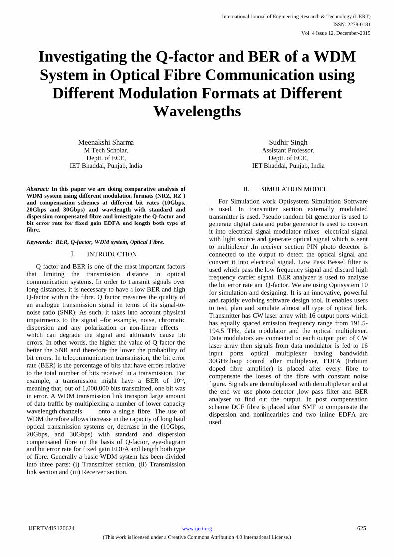
II. SIMULATION MODEL
For Simulation work Optisystem Simulation Software
is used. In transmitter section externally modulated
transmitter is used. Pseudo random bit generator is used to
generate digital data and pulse generator is used to convert
it into electrical signal modulator mixes electrical signal
with light source and generate optical signal which is sent
to multiplexer .In receiver section PIN photo detector is
connected to the output to detect the optical signal and
convert it into electrical signal. Low Pass Bessel filter is
used which pass the low frequency signal and discard high
frequency carrier signal. BER analyzer is used to analyze
the bit error rate and Q-factor. We are using Optisystem 10
for simulation and designing. It is an innovative, powerful
and rapidly evolving software design tool. It enables users
to test, plan and simulate almost all type of optical link.
Transmitter has CW laser array with 16 output ports which
has equally spaced emission frequency range from 191.5-
194.5 THz, data modulator and the optical multiplexer.
Data modulators are connected to each output port of CW
laser array then signals from data modulator is fed to 16
input ports optical multiplexer having bandwidth
30GHz.loop control after multiplexer, EDFA (Erbium
doped fibre amplifier) is placed after every fibre to
compensate the losses of the fibre with constant noise
figure. Signals are demultiplexed with demultiplexer and at
the end we use photo-detector ,low pass filter and BER
analyser to find out the output. In post compensation
scheme DCF fibre is placed after SMF to compensate the
dispersion and nonlinearities and two inline EDFA are
used.
International Journal of Engineering Research & Technology (IJERT)
ISSN: 2278-0181
www.ijert.orgIJERTV4IS120624
(This work is licensed under a Creative Commons Attribution 4.0 International License.)
Vol. 4 Issue 12, December-2015
625
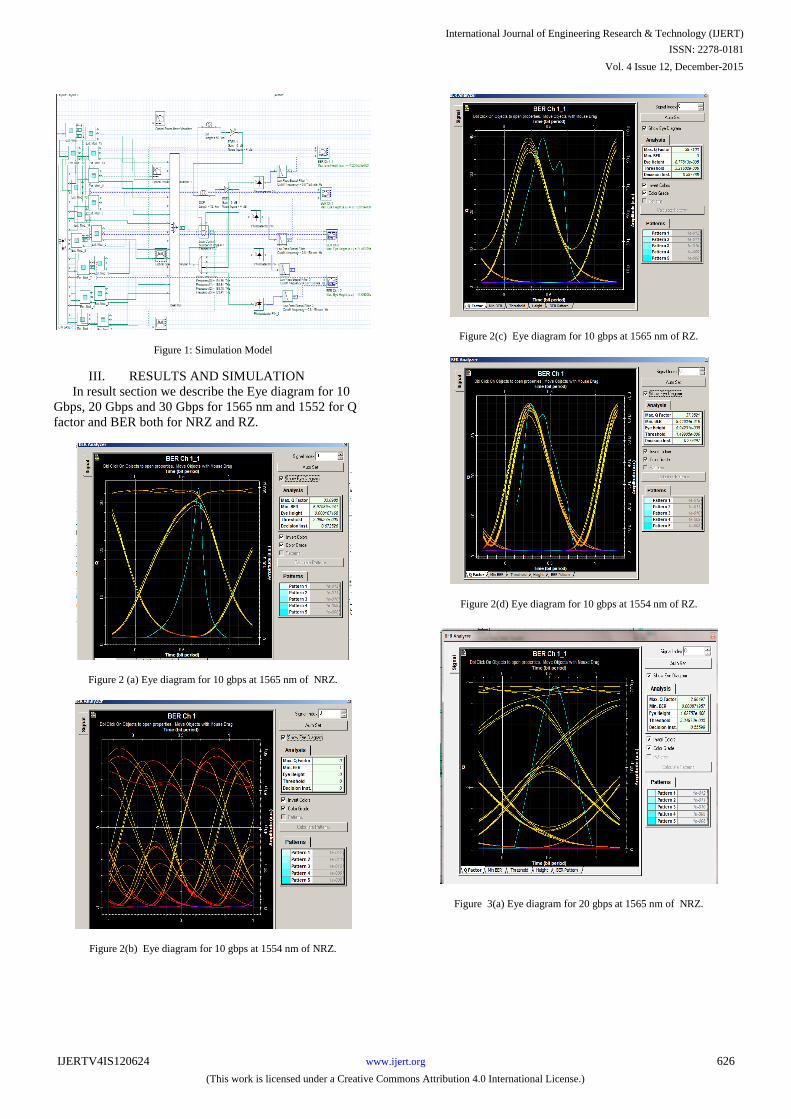
Figure 1: Simulation Model
III. RESULTS AND SIMULATION
In result section we describe the Eye diagram for 10
Gbps, 20 Gbps and 30 Gbps for 1565 nm and 1552 for Q
factor and BER both for NRZ and RZ.
Figure 2 (a) Eye diagram for 10 gbps at 1565 nm of NRZ.
Figure 2(b) Eye diagram for 10 gbps at 1554 nm of NRZ.
Figure 2(c) Eye diagram for 10 gbps at 1565 nm of RZ.
Figure 2(d) Eye diagram for 10 gbps at 1554 nm of RZ.
Figure 3(a) Eye diagram for 20 gbps at 1565 nm of NRZ.
International Journal of Engineering Research & Technology (IJERT)
ISSN: 2278-0181
www.ijert.orgIJERTV4IS120624
(This work is licensed under a Creative Commons Attribution 4.0 International License.)
Vol. 4 Issue 12, December-2015
626
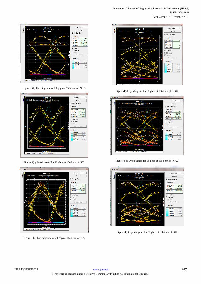
Figure 3(b) Eye diagram for 20 gbps at 1554 nm of NRZ.
Figure 3(c) Eye diagram for 20 gbps at 1565 nm of RZ.
Figure 3(d) Eye diagram for 20 gbps at 1554 nm of RZ.
Figure 4(a) Eye diagram for 30 gbps at 1565 nm of NRZ.
Figure 4(b) Eye diagram for 30 gbps at 1554 nm of NRZ.
Figure 4(c) Eye diagram for 30 gbps at 1565 nm of RZ.
International Journal of Engineering Research & Technology (IJERT)
ISSN: 2278-0181
www.ijert.orgIJERTV4IS120624
(This work is licensed under a Creative Commons Attribution 4.0 International License.)
Vol. 4 Issue 12, December-2015
627

Figure 4 (d) Eye diagram for 30 gbps at 1554 nm of RZ.
Table 1 comparison table for Q factor of NRZ and RZ
Data
Rate
Wavelength NRZ RZ
10 1565 33.0985 39.7103
10 1554 0 37.9521
20 1565 2.96 3.91491
20 1554 6.26 7.82827
30 1565 No result 1.75103
30 1554 2.2385 2.91277
Table 2 Comparison table for BER of NRZ and RZ
Date Rate
Wavelength NRZ RZ
10 1565 6.97589e- 241 0
10 1554 1 9.44834e- 316
20 1565 0.0087 2.52061e- 005
20 1554 1.592e- 010 1.7842e- 015
30 1565 No result 0
30 1554 0.0093674 9.44834e- 316
IV.CONCLUSIONS
In this paper we have analysed 8 channels DWDM
optical communication system for post dispersion
compensation scheme using DCF using different
modulation system NRZ, RZ at different bit rates 10Gbps,
20Gbps and 30 Gbps. We observed that RZ format gives
better performance on the basis of Q factor, bit error rate
(BER) and eye opening. In this we can say that RZ
modulation format is faithful for long distance
communication.
V. REFERENCES
[1] Meenakshi Sharma, Navpreet Kaur “Analysis of DWDM
system using different modulation and compensation
technique at different bit rates” IJEETE Vol.02, Issue 04,
Jul-Aug 2015, Pg 219-223.
[2] Govind P. Agrawal, “Fibre-optic communication systems,”
Third edition, 2002, John Wiley & Sons, Inc, ISBN:0- 471-
21571-6.
[3] Gerd Keiser, “Optical fibre communications,” third edition,
2000, McGraw-Hill Higher Education, ISBN: 0-07-116468-
5.
[4] Gupta, S.; Shukla, N. K.; Jaiswal, S., "Pre-post, symmetric1
and 2 compensation techniques with RZ modulation,"
Recent Advances in Information Technology (RAIT), 2012
1st International Conference on , vol., no.pp.251,255, 15-17
March 2012.
[5] Buckley Sean “Beyond-100G,” Fujistu network
communications inc.
[6] R. Llorente, R. Clavero, F. Ramos, J. Marti, “Linear and
nonlinear crosstalk evaluation in DWDM networks using
optical Fourier transforms,” EURASIP Journal on Applied
Signal Processing Volume 2005, 1 January 2005, Pages
1593-1602.
[7] L. Zhu, Y. Zhang, Y. Dong, M. Chen, L. Xia and S. Xie,
“Impact of optical (de)multiplexers on 40 Gbit/s WDM
transmission system”, Optics Communications, Elseiver,
2003, Vol. 217, pp. 221-225.
VI. BIBLIOGRAPHY
Meenakshi Sharma has completed her bachelor’s degree in
Electronics and Communication Engineering (ECE) from
Swami Parmanand College of Engineering and
Technology, Lalru, Punjab, India and pursuing master’s
degree in Electronics and Communication (ECE) from IET
Bhaddal, Ropar, Punjab, India.
Sudhir Singh working as Assistant Professor in department
of ECE at IET, Bhaddal, Ropar, Punjab, India. He has
completed his research work in ECE from Doaba Institute
of Engineering and Technology, Kharar, Punjab, India and
has received bachelor’s degree from IET, Bhaddal, Ropar,
Punjab, India.
International Journal of Engineering Research & Technology (IJERT)
ISSN: 2278-0181
www.ijert.orgIJERTV4IS120624
(This work is licensed under a Creative Commons Attribution 4.0 International License.)
Vol. 4 Issue 12, December-2015
628