ip camera tester - radio partscctv tester and use properly. for using the cctv tester safely, please...
TRANSCRIPT
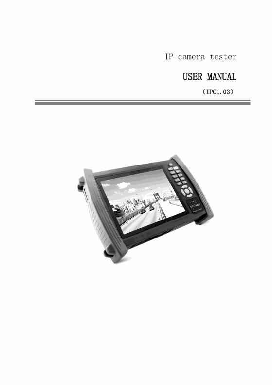
IP camera tester
USER MANUAL
(IPC1.03)
Thank you for purchasing the CCTV security tester. Please read the manual before using the
CCTV tester and use properly.
For using the CCTV tester safely, please first read the「Safety Information」carefully in the
manual.
The manual should be kept well in case of reference.
Keep the S/N label for after-sale service within warranty period. Product without S/N label will
be charged for repair service.
If there is any question or problem while using the CCTV tester, or damages occurred on the
product, please contact our technical Department.

Content
1 .Safety information ...............................................................................................................................1
2. IP camera tester Introduction ...............................................................................................................2
2.1 General ......................................................................................................................................2
2.2 Features......................................................................................................................................2
2.3 Function .....................................................................................................................................4
2.3.6 Enhanced Color bar generator .................................................................................................4
2.3.7 DC12V 2A/DC 5V 2A output power ......................................................................................6
2.3.8 Audio testing ...........................................................................................................................6
2.3.9 Cable tester .............................................................................................................................6
2.3.10 PTZ data analysis ..................................................................................................................6
2.3.12 Video screenshot, record and playback .................................................................................6
2.3.13 DHCP dynamic address assignment ......................................................................................6
2.3.14 the dynamic address accessed ...............................................................................................7
2.3.15 Multi- segment IP Camera Test .............................................................................................7
2.3.25 WIFI .....................................................................................................................................8
2.3.26 SDI camera test (*optional) ............................................................................................8
2.3.27 PoE power supply .................................................................................................................8
2.3.28 HDMI signal output ..............................................................................................................9
2.3.29 Network bandwidth testing ...................................................................................................9
2.3.30 Cable search (Optional) .........................................................................................................9
2.3.31 Screen rotation Display .........................................................................................................9
2.4 Packing list ................................................................................................................................9
2.5 Function ...................................................................................................................................10
3. Operation ...................................................................................................................................14
3.1 Installing the Battery ................................................................................................................14
3.2 Instrument connection ..............................................................................................................15
3.2.1 IP camera connection ............................................................................................................15

3.2.2 Analog camera test ..............................................................................................................16
3.3 OSD menu ...............................................................................................................................16
3.3.1Video monitor test ..........................................................................................................19
3.3.2 Color-bar generator (TV OUT) .....................................................................................27
3.3.3 ONVIF ..........................................................................................................................28
3.3.4 IP camera test ................................................................................................................36
3.3.5 IP address scan ..............................................................................................................38
3.3.6 PING test.......................................................................................................................39
3.3.7 Cable test.......................................................................................................................40
3.3.8 Cable scan .....................................................................................................................40
3.3.9 Port flash .......................................................................................................................42
3.3.10 Data monitor ...............................................................................................................43
3.3.11 Optical power meter (Optional ) ...........................................................................43
3.3.12 Visual Fault Locator(optional) ...............................................................................45
3.3.13 Digital Multi-meter (optional ) .............................................................................47
3.3.14 Video Player ................................................................................................................54
3.3.15 Music player ................................................................................................................55
3.3.16 LED lamp (Flashlight).................................................................................................56
3.3.17 PoE test .......................................................................................................................57
3.3.18 TDR cable test (optional) ...................................................................................57
3.3.19 Calculator ....................................................................................................................60
3.3.20 Browser .......................................................................................................................61
3.3.21 IPC viewer ..................................................................................................................61
3.3.22 DC12V power output, PoE power supply ....................................................................63
3.3.23 Application tools .........................................................................................................64
3.3.24 APPS Tools .................................................................................................................71
3.3.25 System Set ...................................................................................................................72
3.3.26 Update .........................................................................................................................73
3.4 Audio test .................................................................................................................................74

3.5 HDMI output ...........................................................................................................................74
3.6 PoE power................................................................................................................................74
3.7 DC12V 2A power output .........................................................................................................75
3.7 USB 5V 2A power output ........................................................................................................76
4. Specifications .............................................................................................................................77
4.1 General Specifications .............................................................................................................77
4.2 Multi-meter specifications .......................................................................................................79
4.3 Optical power meter specifications ..........................................................................................81
4.4 Visual fault locator specifications ............................................................................................82
Page.1.
1 .Safety information
◆ The tester is intended to use in compliance with the local rules of the electrical usage and avoid to
apply at the places which are inapplicable for the use of electrics such as hospital, gas station etc.
◆ To prevent the functional decline or failure, the product should not be sprinkled or damped.
◆ The exposed part of the tester should not be touched by the dust and liquid.
◆ During transportation and use, it is highly recommended to avoid the violent collision and vibration
of the tester, lest damaging components and causing failure.
◆Don’t leave the tester alone while charging and recharging. If the battery is found severely hot, the
tester should be powered off from the electric source at once. The tester should not be charged over 8
hours.
◆ Don’t use the tester where the humidity is high. Once the tester is damp, power off immediately and
move away other connected cables.
◆ The tester should not be used in the environment with the flammable gas.
◆ Do not disassemble the instrument since no component inside can be repaired by the user. If the
disassembly is necessary indeed, please contact with the technician of our company.
◆ The instrument should not be used under the environment with strong electromagnetic interference.
◆ Don’t touch the tester with wet hands or waterish things.
◆ Don’t use the detergent to clean and the dry cloth is suggested to use. If the dirt is not easy to remove,
the soft cloth with water or neutral detergent can be used. But the cloth should be tweaked sufficiently.
About Digital Multi-meter
◆ Before using, you must select the right input jack, function and range.
◆ Never exceed the protection limit values indicated in specifications for each range of measurement.
◆When the meter is linked to a measurement circuit, do not touch unused terminals.
◆Do not measure voltage if the voltage on the terminals exceeds 660V above earth ground.
◆At the manual range, when the value scale to be measured is unknown beforehand, set the range
selector at the highest position.
◆Always be careful when working with voltages above 60V DC or 40V AC, keep fingers behind the
probe barriers while measuring.
◆Never connect the meter with any voltage source while the function switch is in the current,
Page.2.
resistance, capacitance, diode, continuity, otherwise it will damage the meter.
◆Never perform capacitance measurements unless the capacitor to be measured has been discharged
fully.
◆Never measure any of resistance, capacitance, diode or continuity measurements on live circuits.
Visual laser sources
When you turn on visual laser sources, please don’t stare at it, or will damage to eyes
When not using it,Please turn it off and cover the protective cap .
2. IP camera tester Introduction
2.1 General
7 inch Touch Screen IPC camera tester is for maintenance and installation of IP camera and Analogue
camera ,display HD camera and analogue camera image ,PTZ control, easy to use and operate .
Built in network testing tools (IP address search, PING etc), quickly check the IP camera problem.
Cable scan, TDR tester, easy to check the network cable, BNC cable problem. Optical power meter,
Visual fault detector function, effective to solve the optical fiber transmission problem.
2.2 Features
7 inch 800×600 touch screen, easy to operate
Support ONVIF camera test
Support Dahua,HIKVISION,ACTI ,H.264/MPEG4/MJPEG camera test etc( Customize)
Built in Wi-Fi ,can receive wireless camera(ONVIF and customize camera)
SDI Digital camera image display, record and screenshots * (Optional)
HDMI signal input,support1080P*(Optional)
HDMI signal output,support1080P
Analogue video image display, Auto adapt and display the video format of NTSC/PAL
Support more than 30 protocols ,such as PELCO-P、PELCO-D、SAMSUNG etc
Video image magnification, to view the details, easy to use
Page.3.
Snapshot and save the current image as JPG file in the SD card, video record and playback
LED Lamp, easy to operate at night
Micro SD card moveable
LCD screen brightness/contrast/color Saturation adjustable
Visual fault locator , to test fiber’s bending and breakage(Optional)
Optical power meter ,test fiber loss and value
Digital Multi-meter , DC and AC voltage measurement, Resistance measurement,
Continuity test, Diode measurements, Capacitance measurement(Optional)
Enhanced Color bar generator, Video Generating, the PAL/NTSC multi-system color bar video
generator (Eight-system switchable, transmit/receive eight-system colorful imagines).
PEAK video signal level, SYNC signal level, COLOR BURST chroma level measurement,test
video signal attenuation (Optional)
Cable scan, Send the specific signal, easy to find the connected cable.
PING is the most conventional network debugging tools; It is used for testing if the connected IP
camera or other network equipment’s Ethernet port is working normally and the IP address is
correct.
In digital IP surveillance applications, if IP camera’s IP address is not clear or forgotten; the
device cannot be used .IP address scan can quickly search the connected IP camera or other
network device’s IP address.
PoE voltage test,It can test the PoE voltage when the POE switch is supplying the POE power to
IP camera ,wireless AP etc
TDR cable test,test cable length and short-circuit (Optional)
Cable test , Test LAN cable or telephone cable,UTP cable etc ,cable type and the sequence of
wires will be displayed
Support RS232/RS485,Rate 600 ~ 115200bps adjustable
PTZ protocol analysis, control protocol command displays to check RS485 transmission
Whether is normal, easy to find the fault device
PTZ control. Pan/tilts the P/T unit, zooms in/out the lens, adjusts the focus, aperture and
sets and the preset position
Page.4.
DC12V 2A output power for camera
PoE power output,supply temporary power for PoE camera
DC5V 2A power output,as a power bank
Audio input test, test the audio signal from pickup devices
7.4V 48.1Wh Battery energy display, It can last 16hours for normal use after charging for 8
hours
2.3 Function
2.3.1 Touch screen and OSD menu
IPC camera tester use capacitive touch screen operation,easy to use and improve work efficiency.
The function icons can move to APPS tool file and menu, the common function keep on the main menu,
the others be move to Apps tool file, the menu more clearly.
2.3.2 IP camera test
Built in ONVIF test, IP camera tester, browser function etc, display IP camera image and change IP
address. 7 inch 800×600 screen display,Larger viewing angle, it convenient engineers to locate the
network camera. Built in ONVIF TOOLS and PTZ control, IP camera protocols customized ,support
test more than 30 IP camera types now ,such as ACTi、Dahua IPC-HFW2100P、
Hikvision,DS-2CD864-E13、Samsung SNZ-5200、Tiandy TD-NC9200S2、Kodak IPC120L、Honeywell
HICC-2300T、Aipu-waton IP5000-BC-13MP/IRS06-13MP、fine-Tida IPC、FSJ BY-1080Q、WEISKY
IPC camera etc.
2.3.3 Analog camera test
Display analog camera image ,7 inch 800×600 LCD screen display ,larger viewing angle ,More
intuitively and easily display the camera image quality. Support PAL/NTSC format image signal .
LCD screen backlight brightness adjustable, and analog video image brightness/contrast/color
Saturation adjustable.
2.3.4 Video level meter
PEAK video signal level, SYNC signal level, COLOR BURST chroma level measurement

Page.5.
Use hardware high-frequency sampling and processing technology; test the Peak video signal, SYNC
signal level, COLOR BURST chroma level more accurate.
PEAK video signal level: Measuring peak video signal, the video signal level is 1000±175mV in PAL
format (NTSC format :140±15IRE ), the level is too low will cause the image to dim, reducing dynamic
range; Level is too high will lead to virtual shadow, reducing the definition of the image .
The SYNC signal level: measuring the amplitude of the video sync pulse, for determining the video
level is correct and that the coaxial cable connectivity. Sync level range is 300 ± 35mV in PAL
format(NTSC format: 40 ± 5IRE ), the level is too low will cause the image to fracture or scroll; Level
is too high will reduce the image color levels and dynamic range.
COLOR BURST chroma level: Measuring camera color burst level, to determine whether the coaxial
cable transmission for the best detail and color. Chroma standard level is 280mV in PAL format and is
40 IRE in NTSC format. Chroma level is low,Chroma level is low, the color will become dark, color
level is too low, the details of monitor reception image will be lost and even become black and
white; chroma level is too high, the image will be displayed spot , affect the image detail and clarity.
Coaxial cable is too long will reduce the chroma level.
2.3.5 PTZ controller
Display the input video images. Pan/tilt the P/T unit and zoom in/ out the image. Setup the controlling
parameters like protocol, communication port, baud rate, PTZ ID, pan/tilt speed; set and call preset
position.
2.3.6 Enhanced Color bar generator
Video Generating, the PAL/NTSC multi-system color bar video generator (Eight-system switchable,
transmit/receive eight-system colorful imagines). By receiving the video color bar to test the video
channel whether transmit normally. And judge whether the color is different, because of the
transmission loss or interference, it suitable for Video transmission of the field tests, such as optical
video transmitter and receiver, video cable etc.
The new function color bar can test the image whether shift.
The color bar (red, green, blue, white, black) test the monitor whether have white or black dot etc.
Page.6.
2.3.7 DC12V 2A/DC 5V 2A output power
Power the camera with DC12V (1A) power output from the tester. It is helpful for demo and testing
when the power supply is not available. Built in DC5V2A power output,as a power bank .
2.3.8 Audio testing
Test the audio input from pickup devices. Connect the tester and pickup device with the audio cable.
Recording can save.
2.3.9 Cable tester
Test LAN cable or telephone cable.
Connect LAN cable or telephone cable with the CCTV tester and cable tester. And then the connecting
status, cable type and the sequence of wires will be displayed, as well as the serial number of the cable
tester kit.
2.3.10 PTZ data analysis
Search the Control protocol code from Multifunction keyboard or DVR by RS485 /RS232 interface, test
the PTZ control command data whether received anomaly and RS485/RS232 data transmission.
Screen displays 16 hexadecimal codes such as
PELCO-P:A0 00(Add) xx xxxxxx AF xx
PELCO-D:FF 01(Add)xx xxxxxxxx
2.3.11 Image magnification
Set image zoom, can view and display the details .Support ONVIF 、DaHua、Hikvision、ACTi、
Samsung camera etc.
2.3.12 Video screenshot, record and playback
Capture the video image and save the current video frames as JPEG file, record and save the current
video in the SD card, video image and record files are saved in the SD card. Storage file directory can
be created according to the date.
2.3.13 DHCP dynamic address assignment
Built in DHCP server, dynamic assign address for the IP camera or network device
Page.7.
2.3.14 the dynamic address accessed
Tester can accessed IP address assignment from DHCP, as the tester’s IP address, so not need manual
set it.
2.3.15 Multi- segment IP Camera Test
Support Multi- segment Static IP address setting,,Can simultaneously test different segments IP
network cameras
2.3.16 IP address scan
In digital IP surveillance applications, if IP camera’s IP address is not clear or forgotten; the device
cannot be used .IP address scan can quickly search the connected IP camera or other network device’s
IP address.
2.3.17 PING Test
PING is the most conventional network debugging tools; It is used for testing if the connected IP
camera or other network equipment’s Ethernet port is working normally and the IP address is correct.
2.3.18 Port Flashing
The tester will send special signals to make the connected POE port flicker at special frequency, which
will enable the installers to easily and quickly find the connected ethernet cable. This function can
prevent mistakenly insertion or disconnection non-corresponding cable to artificially interrupt network
connection.
2.3.19 PoE Test
It can test the PoE voltage when the POE switch is supplying the POE power to IP camera. It can
clearly display the power+ and power- on the Ethernet cable pins, each cable pin’s voltage and the
failure connection of cable pin series numbers.
2.3.20 Digital Multi-meter (Optional)
CCTV Tester built in highly stable and reliable 33/4 digit (6600) digital multi-meter. It is used for the
DC and AC voltage measurement, AC and DC current measurement, Resistance measurement,
Continuity test, Diode measurements, Capacitance measurement, Auto/Manual measuring range
switching, relative value measurement and locking. It is easy operation and professionally accurate.

Page.8.
2.3.21 Visual fault locator (Optional)
Visual Fault Locator with 650nm wavelength can emit red laser sources to test multi-mode and single
mode fiber’s bending and breakage, and Continuous light-emitting and 1HZ, 2Hz modulating light
output. It is indispensable tool in fiber project constructing, fiber net-work maintaining, optical
component manufacture and research.
2.3.22 Optical Power Meter (Optional)
The New tester adopts the most advanced handheld instrument specific integrated chip , achieve
ultra-low power operation, with the 3.5 TFT-LCD High-definition screen display ,five wavelength
calibration points 1625nm,1550nm ,1490nm , 1310nm , 1300nm , 850nm.Linear or nonlinear optical
power display, it can measure the optical power value, and also be used for Relative measurement of
optical fiber link loss. It is necessary tool for fibre-optic communication, cable television system and
security system maintenance.
2.3.23 LED lamp
It is useful for the Engineer to install and maintain security system at night. Press button LED On/Off,
easy operation.
2.3.24 TDR cable length and short circuit measurement (Optional)
TDR cable testing, accurately measure BNC cable, network cable, controls cable’s length and
short-circuits location. It improves working efficiency.
2.3.25 WIFI
Built in WIFI, can receive wireless camera (ONVIF and customize camera) or network data etc.
2.3.26 SDI camera test (*optional)
SDI digital video surveillance testing, support 720P/1080P digital camera image test and video
image zoom, record ,screenshots, Photo viewer and playback .
2.3.27 PoE power supply
Support PoE power supply,High capacity 48.1WhLithium polymer battery, Provides temporary
power for the PoE network camera .

Page.9.
2.3.28 HDMI signal output
With HDMI output port, support 1080P output, record and media files playback
Via connect HDMI port output to HD TV display
2.3.29 Network bandwidth testing
Network channel bandwidth test, need two instruments to test, one as a transmitter, the other as a
receiver, also can install test software in the PC, combine with instrument to test Network
channel bandwidth
2.3.30 Cable search (Optional)
Send the specific signal, easy to find the connected cable.
2.3.31 Screen rotation Display
Support screen 180 degree rotations (manual set), the network port will be on the top, to convenient
connect the cable.
2.4 Packing list
1). Tester
2). Adapter Polymer Battery(7.4V DC 6500mAh )
5). BNC cable
6). RS485 cable
7).SC,ST connector(Only for optical power meter)
8).Multi-meter test leads one pair of red and black (only for the Multi-meter models)
9). Output Power cable
10). Audio cable
11). TDR alligator clamp (only for TDR models)
12). Safety cord
13). Tool bag
14). Manual
15) 4G SD card
Page.10.
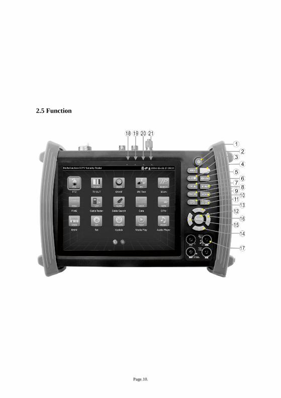
2.5 Function
Page.11.
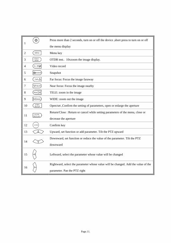
1 Press more than 2 seconds, turn on or off the device ,short press to turn on or off
the menu display
2 Menu key
3 OTDR test。10xzoom the image display.
4 Video record
5 Snapshot
6 Far focus: Focus the image faraway
7 Near focus: Focus the image nearby
8 TELE: zoom in the image
9 WIDE: zoom out the image
10 Open/set ,Confirm the setting of parameters, open or enlarge the aperture
11
Return/Close : Return or cancel while setting parameters of the menu, close or
decrease the aperture
12
Confirm key
13 Upward, set function or add parameter. Tilt the PTZ upward
14
Downward, set function or reduce the value of the parameter. Tilt the PTZ
downward
15
Leftward, select the parameter whose value will be changed
16
Rightward, select the parameter whose value will be changed. Add the value of the
parameter. Pan the PTZ right
Page.12.
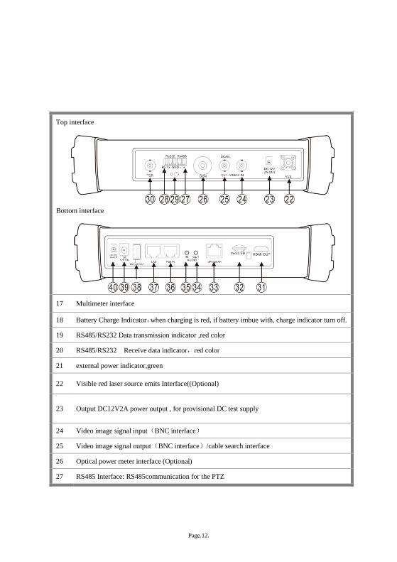
Top interface
Bottom interface
17 Multimeter interface
18 Battery Charge Indicator,when charging is red, if battery imbue with, charge indicator turn off. 19 RS485/RS232 Data transmission indicator ,red color
20 RS485/RS232 Receive data indicator,red color
21 external power indicator,green
22 Visible red laser source emits Interface((Optional)
23 Output DC12V2A power output , for provisional DC test supply
24 Video image signal input(BNC interface)
25 Video image signal output(BNC interface)/cable search interface
26 Optical power meter interface (Optional)
27 RS485 Interface: RS485communication for the PTZ
Page.13.
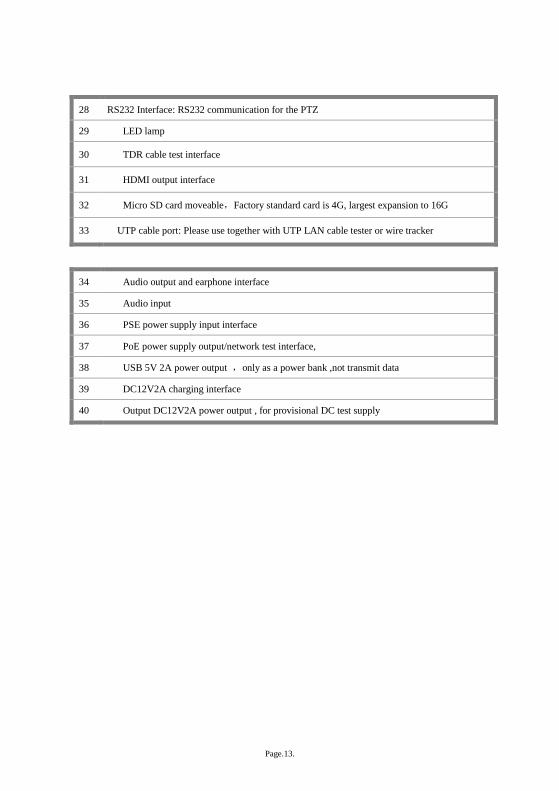
28 RS232 Interface: RS232 communication for the PTZ
29 LED lamp
30 TDR cable test interface
31 HDMI output interface
32 Micro SD card moveable,Factory standard card is 4G, largest expansion to 16G
33 UTP cable port: Please use together with UTP LAN cable tester or wire tracker
34 Audio output and earphone interface
35 Audio input
36 PSE power supply input interface
37 PoE power supply output/network test interface,
38 USB 5V 2A power output ,only as a power bank ,not transmit data
39 DC12V2A charging interface
40 Output DC12V2A power output , for provisional DC test supply
Page.14.
3. Operation
3.1 Installing the Battery
The tester has built-in lithium ion polymer rechargeable battery. The battery cable inside battery
cabin should be disconnected for safety during transportation!
Prior to the use of the instrument, the battery cables inside the battery cabin should be well
connected.
Usually it doesn’t need to disconnect the cable at the normal use
Pressing the key continuously can power on or off the tester.
Notice:Pls use the original adaptor and connected cable of the device!
when charging,show the battery is full or Charge Indicator turns off, Indicates that the battery imbue
with.
Notice: When the Charge Indicator turns off, the battery is approximately 90%
charged. The charging time can be extended for about 1 hour and the charging time within 12
hours will not damage the battery.
Notice :Press the key several seconds to restore the default settings when the
instrument works abnormally.
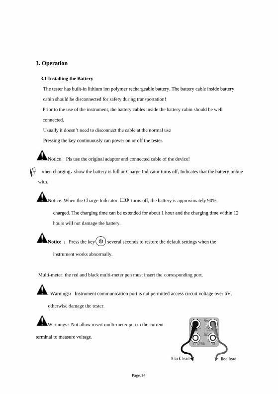
Multi-meter: the red and black multi-meter pen must insert the corresponding port.
Warnings:Instrument communication port is not permitted access circuit voltage over 6V,
otherwise damage the tester.
Warnings:Not allow insert multi-meter pen in the current
terminal to measure voltage.
Page.15.
3.2 Instrument connection
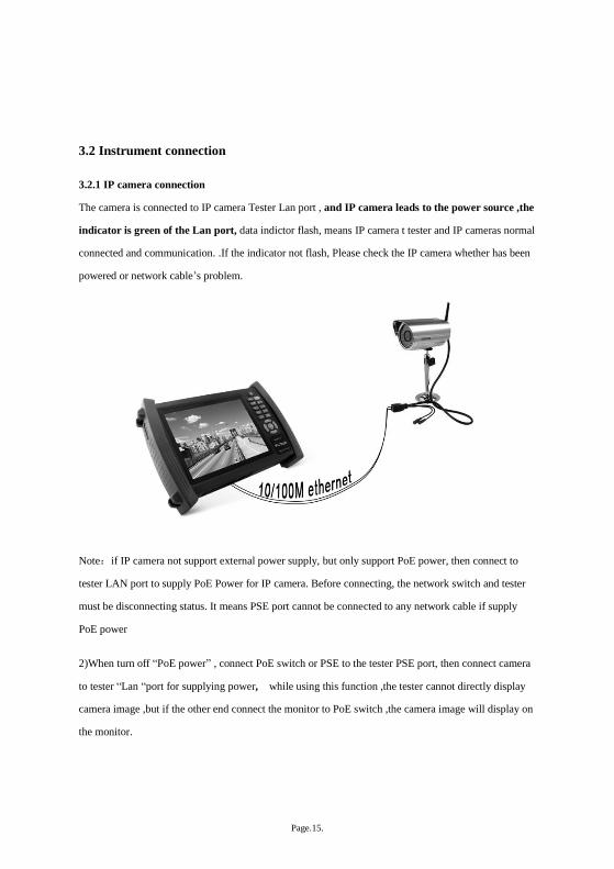
3.2.1 IP camera connection
The camera is connected to IP camera Tester Lan port , and IP camera leads to the power source ,the
indicator is green of the Lan port, data indictor flash, means IP camera t tester and IP cameras normal
connected and communication. .If the indicator not flash, Please check the IP camera whether has been
powered or network cable’s problem.
Note:if IP camera not support external power supply, but only support PoE power, then connect to
tester LAN port to supply PoE Power for IP camera. Before connecting, the network switch and tester
must be disconnecting status. It means PSE port cannot be connected to any network cable if supply
PoE power
2)When turn off “PoE power” , connect PoE switch or PSE to the tester PSE port, then connect camera
to tester “Lan “port for supplying power, while using this function ,the tester cannot directly display
camera image ,but if the other end connect the monitor to PoE switch ,the camera image will display on
the monitor.
Page.16.
Warning:PoE switch or PSE power supply device is only connected to tester “PSE IN” port, or
damage the instruments
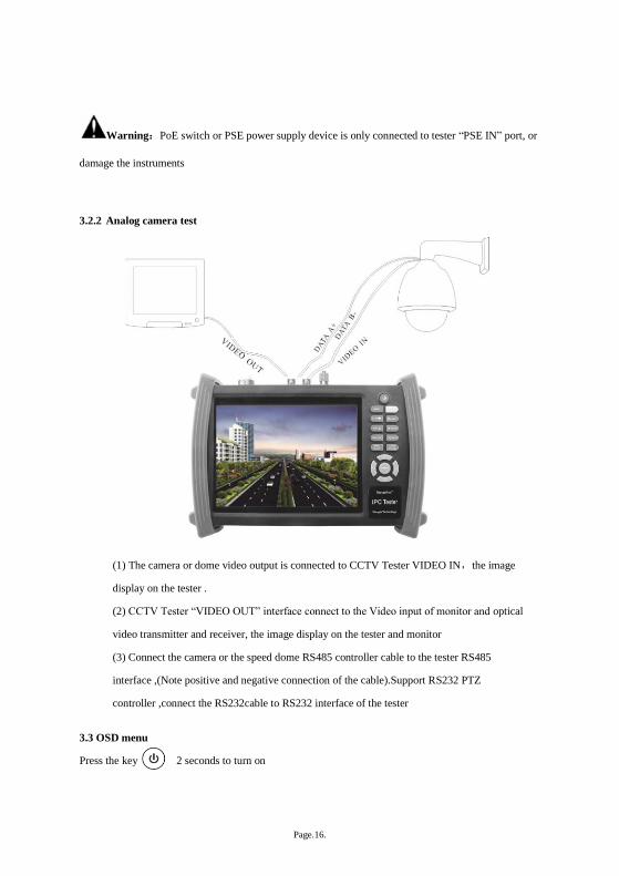
3.2.2 Analog camera test
(1) The camera or dome video output is connected to CCTV Tester VIDEO IN,the image
display on the tester .
(2) CCTV Tester “VIDEO OUT” interface connect to the Video input of monitor and optical
video transmitter and receiver, the image display on the tester and monitor
(3) Connect the camera or the speed dome RS485 controller cable to the tester RS485
interface ,(Note positive and negative connection of the cable).Support RS232 PTZ
controller ,connect the RS232cable to RS232 interface of the tester
3.3 OSD menu
Press the key 2 seconds to turn on

Page.17.
Press the key again to turn off
short press the key to enter sleep mode,press it again to test if tester work abnormally and cannot
be turned off , Press the key several seconds to turn off, the tester reset
Select Icons to enter, if quit, Please click
Click “SD card “, mount or unmount SD card
Click SD card ,mount or Unmount SD card .
Press function Icons seconds, tips: whether move this icons to APPS files, if some function not be often
used, can move that function icons to APPS.
Page.18.
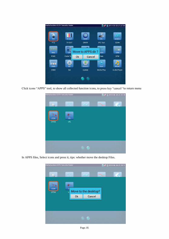
Click icons “APPS” tool, to show all collected function icons, to press key “cancel “to return menu
In APPS files, Select icons and press it, tips: whether move the desktop Files.
Page.19.
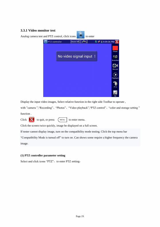
3.3.1 Video monitor test
Analog camera test and PTZ control, click icons to enter
Display the input video images, Select relative function in the right side Toolbar to operate ,
with ”camera ”,“Recording”、“Photos”、“Video playback”,“PTZ control”、“color and storage setting ”
function .
Click to quit, or press to enter menu.
Click the screen twice quickly, image be displayed on a full screen.
If tester cannot display image, turn on the compatibility mode testing. Click the top menu bar
“Compatibility Mode is turned off” to turn on .Can shows some require a higher frequency the camera
image.
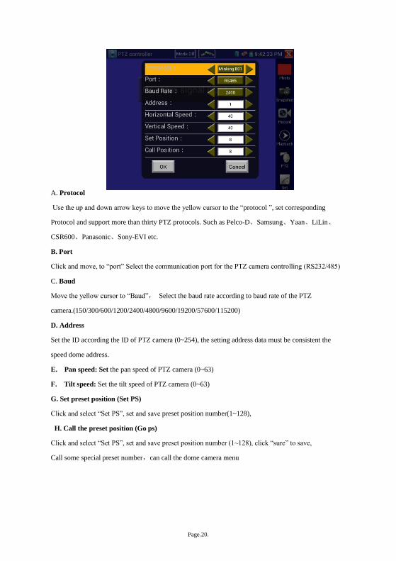
(1) PTZ controller parameter setting
Select and click icons “PTZ”,to enter PTZ setting:
Page.20.
A. Protocol
Use the up and down arrow keys to move the yellow cursor to the “protocol ”, set corresponding
Protocol and support more than thirty PTZ protocols. Such as Pelco-D、Samsung、Yaan、LiLin、
CSR600、Panasonic、Sony-EVI etc.
B. Port
Click and move, to “port” Select the communication port for the PTZ camera controlling (RS232/485)
C. Baud
Move the yellow cursor to “Baud”, Select the baud rate according to baud rate of the PTZ
camera.(150/300/600/1200/2400/4800/9600/19200/57600/115200)
D. Address
Set the ID according the ID of PTZ camera (0~254), the setting address data must be consistent the
speed dome address.
E. Pan speed: Set the pan speed of PTZ camera (0~63)
F. Tilt speed: Set the tilt speed of PTZ camera (0~63)
G. Set preset position (Set PS)
Click and select “Set PS”, set and save preset position number(1~128),
H. Call the preset position (Go ps)
Click and select “Set PS”, set and save preset position number (1~128), click “sure” to save,
Call some special preset number,can call the dome camera menu
Page.21.
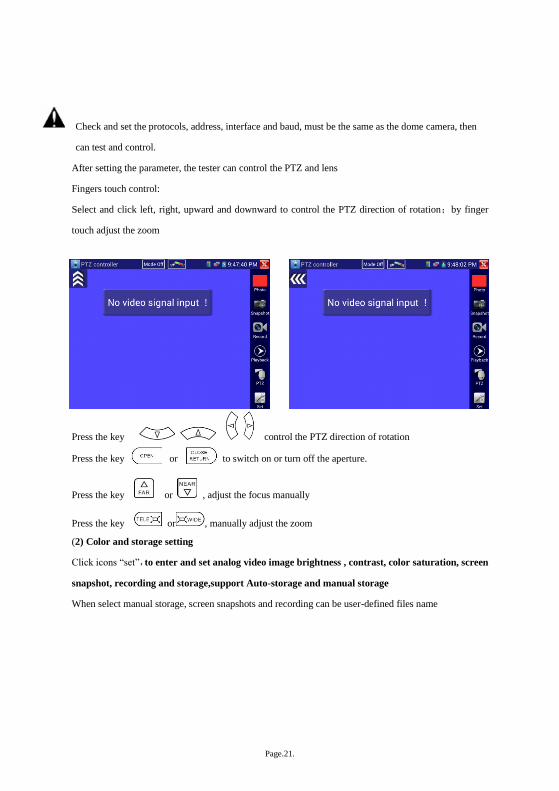
Check and set the protocols, address, interface and baud, must be the same as the dome camera, then
can test and control.
After setting the parameter, the tester can control the PTZ and lens
Fingers touch control:
Select and click left, right, upward and downward to control the PTZ direction of rotation;by finger
touch adjust the zoom
PTZ Control:
Press the key control the PTZ direction of rotation
Press the key or to switch on or turn off the aperture.
Press the key or , adjust the focus manually
Press the key or , manually adjust the zoom
(2) Color and storage setting
Click icons “set”,to enter and set analog video image brightness , contrast, color saturation, screen
snapshot, recording and storage,support Auto-storage and manual storage
When select manual storage, screen snapshots and recording can be user-defined files name

Page.22.
(3) 10x zoom image display and Video out
when image input,press to enter “zoom”,press it again to quit.
Zoom in or zoom out image by fingers touch, When image to enlarge, via finger touch screen to the
left , right, up and down move the image, can clearly see every corner of the image.
if not by touch to operate ,press the key to zoom out , press the key to zoom in, press
upward and downward key to move the image
Notice :If analog video input,resolution is 720*480,when zoom in ,the image not clear, it is

Page.23.
normal, if network digital video input, resolution up to 1280*960,the image is clearer to help confirm
the IP camera installation position.
(4) Snapshots and screenshot
Click the icons “Snapshots “, when the video in, to snapshot and save the current video frame in the SD
card as JPEG file.
if select manual storage ,appears
dialog box “Pls input the files
name” , user-defined the files
name(by Chinese character,
letter ,or Number form ) to save in
SD card, if select “Auto-storage,
the instrument auto-storage the
files after screen shots.
(5) Video record
Click icons “Recording”,when video in,start to record, the recording icons turn to red and flash ,the start
to count, if click the icons again, stop recording and save in the SD card .
if select manual recording ,appears dialog box “Pls input the files name” ,user-defined the files name(by
Chinese character, letter ,or
Number form ) to storage in SD
card, if select “Auto-recording,the
instrument auto-recording the files
after screenshots .
Page.24.
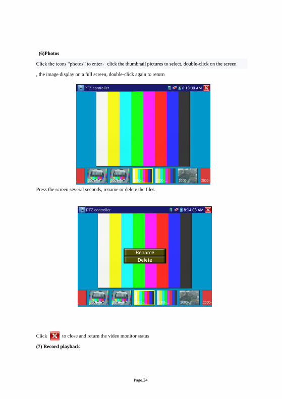
(6)Photos
Click the icons “photos” to enter,click the thumbnail pictures to select, double-click on the screen
, the image display on a full screen, double-click again to return
Press the screen several seconds, rename or delete the files.
Click to close and return the video monitor status
(7) Record playback

Page.25.
Click icons “playback “to enter
Double –click to play,Click on the top right icons to close and return .
In the video "Playback” interface, Press the screen several seconds, rename or delete the files.
Video files also can play in the main menu “Video Player".
(8) Video level meter
Click the icons to enter , se hardware high frequency sampling and processing technology, test
the Peak video signal, SYNC signal level, COLOR BURST chroma level more accurate, when receive
video signal to Auto-test, measure results display the bottom left corner of the screen

Page.26.
While in PAL format, the unit will be mV, While in NTSC format, it will be IRE.
NTSC
Video signal level 140±15IRE
Chroma level( COLOR BURST) 40±5IRE
SYNC signal level 40±5IRE
PAL
Video signal level 1000±200mV
Chroma level( COLOR BURST) 300±35mV
SYNC signal level 300±35mV

Page.27.
PEAK video signal level: Measuring peak video signal, the video signal level is 1000±175mV in PAL
format (NTSC format :140±15IRE ), the level is too low will cause the image to dim, reducing dynamic
range; Level is too high will lead to virtual shadow, reducing the definition of the image
The SYNC signal level: measuring the amplitude of the video sync pulse, for determining the video lev
el is correct and the coaxial cable connectivity. Sync level range is 300 ± 35mV in PAL format
(NTSC format: 40 ± 5IRE), the level is too low will cause the image to fracture or scroll; Level is too
high will reduce the image color levels and dynamic range.
COLOR BURST chroma level: Measuring camera color burst level, to determine whether the coaxial
cable transmission for the best detail and color. Chroma standard level is 280mV in PAL format and is
40 IRE in NTSC format. Chroma level is low, the color will become dark, color level is too low, the
details of monitor reception image will be lost, and even become black and white; chroma level
is too high, the image will be displayed spot , affect the image detail and clarity. Coaxial cable is
too long will reduce the chroma level.
Image loop test:Test video optical transmitter and receiver and video cable , Connect one end to the
tester “VIDEO OUT” port ,and the other end connected to “VIDEO IN” port, the signal sending via
“VIDEO OUT” port ,and receiving via “VIDEO IN port ,if received, display multiple gradually
smaller desktop diagram.
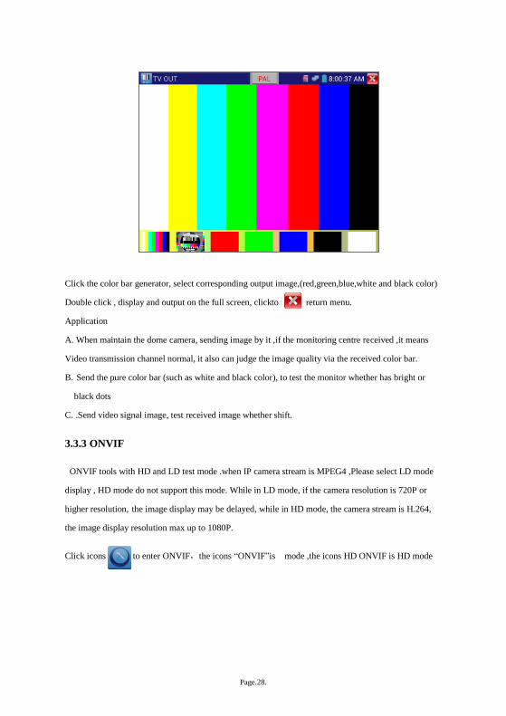
3.3.2 Color-bar generator (TV OUT)
Click to enter,the tester send the color bars from the “Video out” port ,Click the key “PAL”,
select “PAL/NTSC” output formats
Page.28.
Click the color bar generator, select corresponding output image,(red,green,blue,white and black color)
Double click , display and output on the full screen, clickto return menu.
Application
A. When maintain the dome camera, sending image by it ,if the monitoring centre received ,it means
Video transmission channel normal, it also can judge the image quality via the received color bar.
B. Send the pure color bar (such as white and black color), to test the monitor whether has bright or
black dots
C. .Send video signal image, test received image whether shift.
3.3.3 ONVIF
ONVIF tools with HD and LD test mode .when IP camera stream is MPEG4 ,Please select LD mode
display , HD mode do not support this mode. While in LD mode, if the camera resolution is 720P or
higher resolution, the image display may be delayed, while in HD mode, the camera stream is H.264,
the image display resolution max up to 1080P.
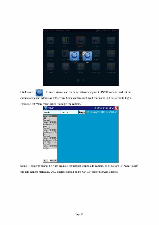
Click icons to enter ONVIF,the icons “ONVIF”is mode ,the icons HD ONVIF is HD mode
Page.29.
Click icons to enter, Auto-Scan the same network segment ONVIF camera, and list the
camera name and address at left screen. Some cameras not need user name and password to login,
Please select “Non- verification” to login the camera.
Some IP cameras cannot be Auto scan, select manual scan to add camera, click bottom left “add”, users
can add camera manually, URL address should be the ONVIF camera service address.
Page.30.
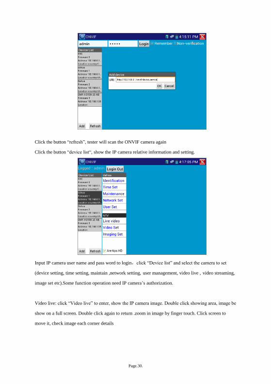
Click the button “refresh”, tester will scan the ONVIF camera again
Click the button “device list“, show the IP camera relative information and setting.
Input IP camera user name and pass word to login,click “Device list” and select the camera to set
(device setting, time setting, maintain ,network setting, user management, video live , video streaming,
image set etc).Some function operation need IP camera’s authorization.
Video live: click “Video live” to enter, show the IP camera image. Double click showing area, image be
show on a full screen. Double click again to return .zoom in image by finger touch. Click screen to
move it, check image each corner details
Page.31.
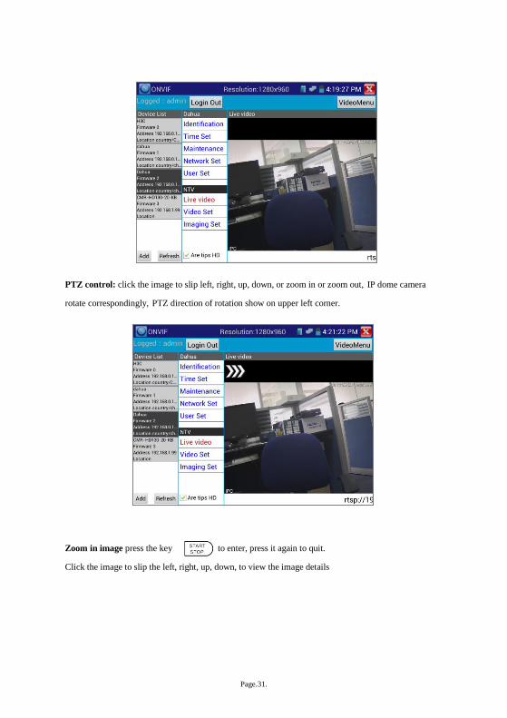
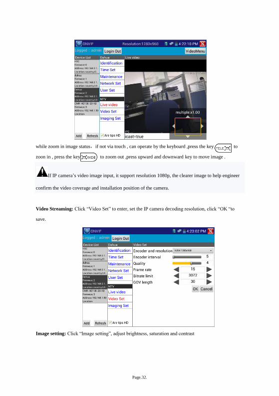
PTZ control: click the image to slip left, right, up, down, or zoom in or zoom out, IP dome camera
rotate correspondingly, PTZ direction of rotation show on upper left corner.
Zoom in image press the key to enter, press it again to quit.
Click the image to slip the left, right, up, down, to view the image details
Page.32.
while zoom in image status,if not via touch , can operate by the keyboard ,press the key to
zoon in , press the key to zoom out ,press upward and downward key to move image .
If IP camera’s video image input, it support resolution 1080p, the clearer image to help engineer
confirm the video coverage and installation position of the camera.
Video Streaming: Click “Video Set” to enter, set the IP camera decoding resolution, click “OK “to
save.
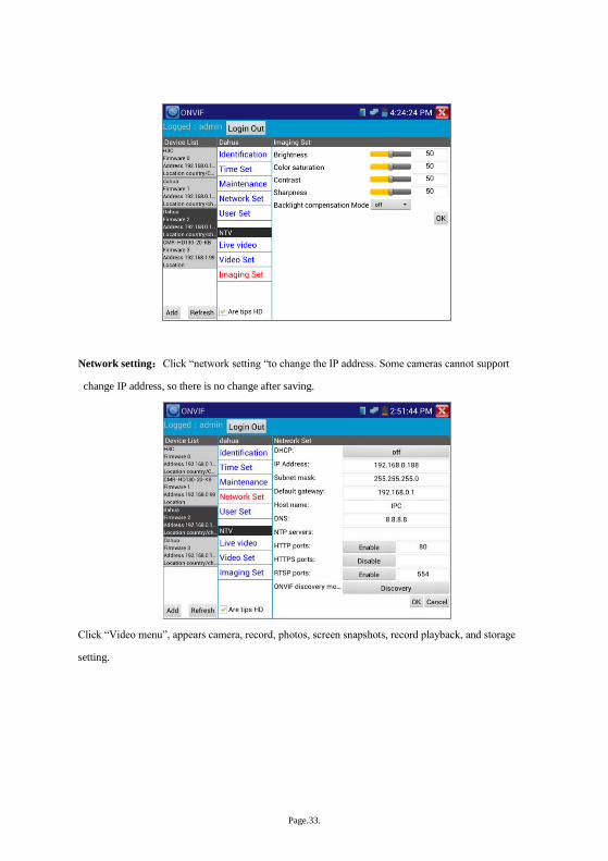
Image setting: Click “Image setting”, adjust brightness, saturation and contrast
Page.33.
Network setting:Click “network setting “to change the IP address. Some cameras cannot support
change IP address, so there is no change after saving.
Click “Video menu”, appears camera, record, photos, screen snapshots, record playback, and storage
setting.
Page.34.
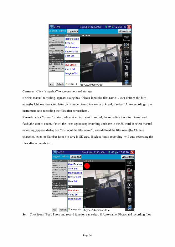
Camera:Click “snapshot” to screen shots and storage
if select manual recording ,appears dialog box “Please input the files name” , user-defined the files
name(by Chinese character, letter ,or Number form ) to save in SD card, if select “Auto-recording,the
instrument auto-recording the files after screenshots .
Record:click “record” to start, when video in,start to record, the recording icons turn to red and
flash ,the start to count, if click the icons again, stop recording and save in the SD card .if select manual
recording ,appears dialog box “Pls input the files name” , user-defined the files name(by Chinese
character, letter ,or Number form ) to save in SD card, if select “Auto-recording,will auto-recording the
files after screenshots .
Set:Click icons “Set”, Photo and record function can select, if Auto-name, Photos and recording files

Page.35.
Auto-storage, if manual, user define files name.
Playback:Click icons “Playback” to display video files, double click to play, click “ ”to return
Press the video files seconds to delete or rename.
Page.36.
Video files can play in the Video player of the main menu
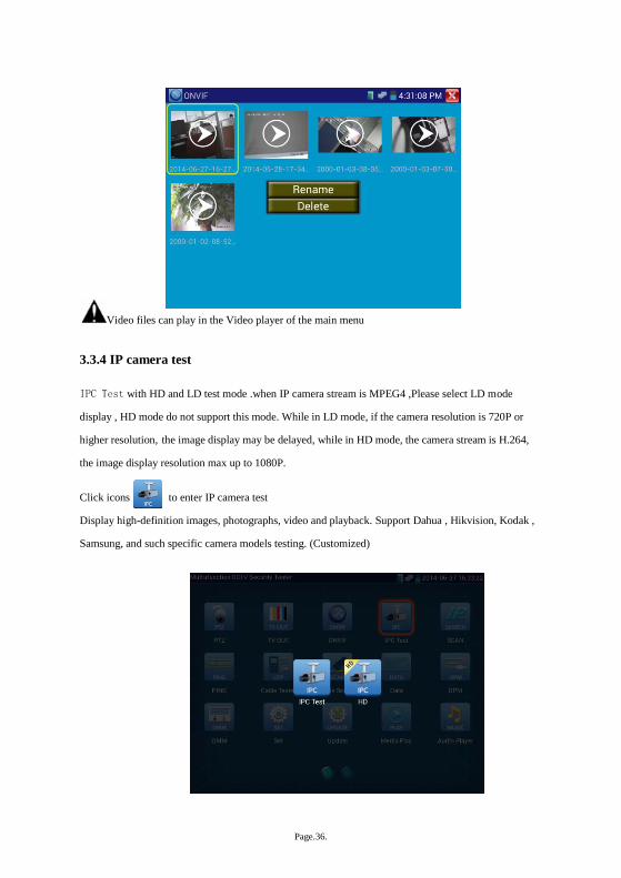
3.3.4 IP camera test
IPC Test with HD and LD test mode .when IP camera stream is MPEG4 ,Please select LD mode
display , HD mode do not support this mode. While in LD mode, if the camera resolution is 720P or
higher resolution, the image display may be delayed, while in HD mode, the camera stream is H.264,
the image display resolution max up to 1080P.
Click icons to enter IP camera test
Display high-definition images, photographs, video and playback. Support Dahua , Hikvision, Kodak ,
Samsung, and such specific camera models testing. (Customized)
Page.37.
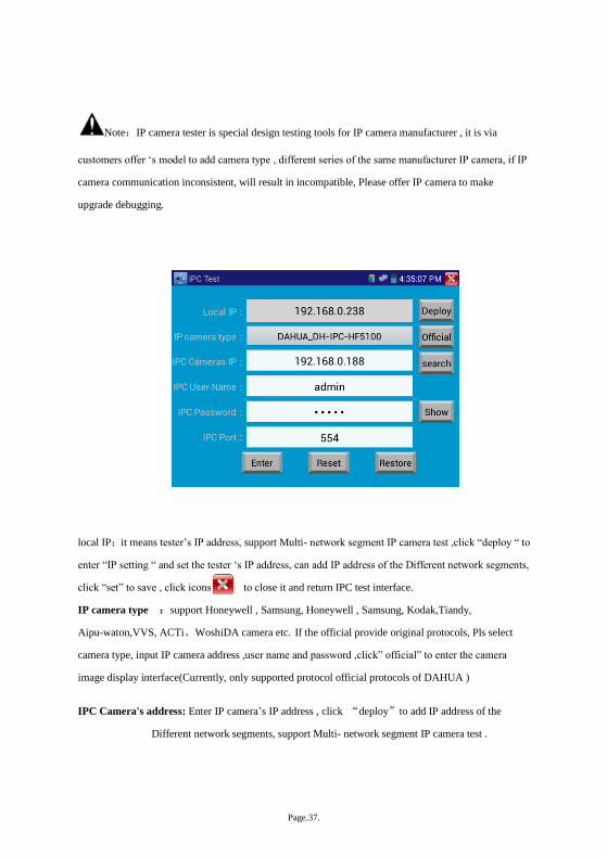
Note:IP camera tester is special design testing tools for IP camera manufacturer , it is via
customers offer ‘s model to add camera type , different series of the same manufacturer IP camera, if IP
camera communication inconsistent, will result in incompatible, Please offer IP camera to make
upgrade debugging.
local IP:it means tester’s IP address, support Multi- network segment IP camera test ,click “deploy “ to
enter “IP setting “ and set the tester ‘s IP address, can add IP address of the Different network segments,
click “set” to save , click icons to close it and return IPC test interface.
IP camera type :support Honeywell , Samsung, Honeywell , Samsung, Kodak,Tiandy,
Aipu-waton,VVS, ACTi、WoshiDA camera etc. If the official provide original protocols, Pls select
camera type, input IP camera address ,user name and password ,click” official” to enter the camera
image display interface(Currently, only supported protocol official protocols of DAHUA )
IPC Camera's address: Enter IP camera’s IP address , click “deploy”to add IP address of the
Different network segments, support Multi- network segment IP camera test .

Page.38.
Click “search” to auto-scan the IP camera’s IP address and display. The tester and IP
cameras connect directly, and then scanned address is only, if not direct connection,
scanning Multiple IP addresses.
IPC User Name: Enter IP camera’s user name
IPC Password: Enter IP camera’s login password, if default enter password, not show relevant letters,
if click “display” to show it.
IPC Port No.:Select IP camera type, it default relative camera port number, and not need change.
After setting, click “login” to enter imager interface.
If IP address setting error or IP camera cannot connection. The tester prompts “Network error”
Click to quit and return IP camera test interface.
IP camera test image and “Video menu” of the ONVIF operation is the same, also with video
image zoom, snapshot, screen shots, record, photos viewer, and playback and save function etc. Please
Ref Video menu” of the ONVIF operation.
3.3.5 IP address scan
Connect the cable to the LAN port, click icons to enter, set initial IP and ending IP address,
instrument’s IP address network segment and scanned network equipment can be the same network
segment or not, then click the key “Start” to scan, each and quickly to search the IP address, also can
Page.39.
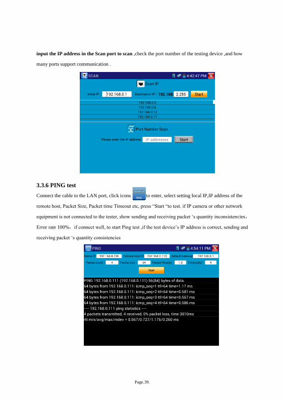
input the IP address in the Scan port to scan ,check the port number of the testing device ,and how
many ports support communication .
3.3.6 PING test
Connect the cable to the LAN port, click icons to enter, select setting local IP,IP address of the
remote host, Packet Size, Packet time Timeout etc, press “Start “to test. if IP camera or other network
equipment is not connected to the tester, show sending and receiving packet ‘s quantity inconsistencies,
Error rate 100%,if connect well, to start Ping test ,if the test device’s IP address is correct, sending and
receiving packet ‘s quantity consistencies
Page.40.
Application:PING testing is the most conventional network debugging tools. It is used for testing if the
connected IP camera or other network equipment’s Ethernet port is working normally and the IP
address is correct.
It’s normal that the first data packet will be lost when test start.
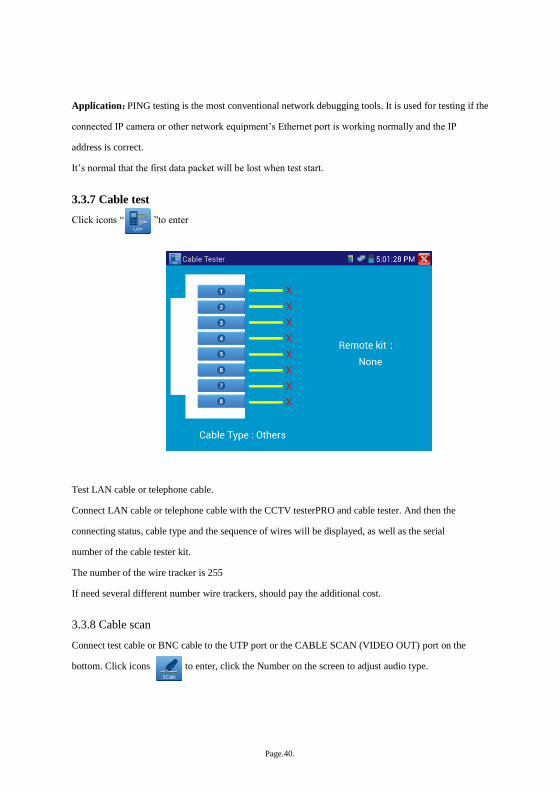
3.3.7 Cable test
Click icons “ ”to enter
Test LAN cable or telephone cable.
Connect LAN cable or telephone cable with the CCTV testerPRO and cable tester. And then the
connecting status, cable type and the sequence of wires will be displayed, as well as the serial
number of the cable tester kit.
The number of the wire tracker is 255
If need several different number wire trackers, should pay the additional cost.
3.3.8 Cable scan
Connect test cable or BNC cable to the UTP port or the CABLE SCAN (VIDEO OUT) port on the
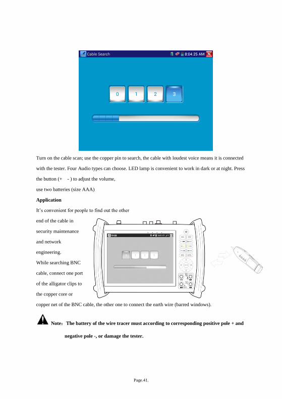
bottom. Click icons to enter, click the Number on the screen to adjust audio type.
Page.41.
Turn on the cable scan; use the copper pin to search, the cable with loudest voice means it is connected
with the tester. Four Audio types can choose. LED lamp is convenient to work in dark or at night. Press
the button (+ - ) to adjust the volume, use two batteries (size AAA)
Application
It’s convenient for people to find out the other
end of the cable in
security maintenance
and network
engineering.
While searching BNC
cable, connect one port
of the alligator clips to
the copper core or
copper net of the BNC cable, the other one to connect the earth wire (barred windows).
Note:The battery of the wire tracer must according to corresponding positive pole + and
negative pole -, or damage the tester.
Page.42.
Note:While receive the audio signal from the tester, it will be influenced by the other
signal and make some noise.
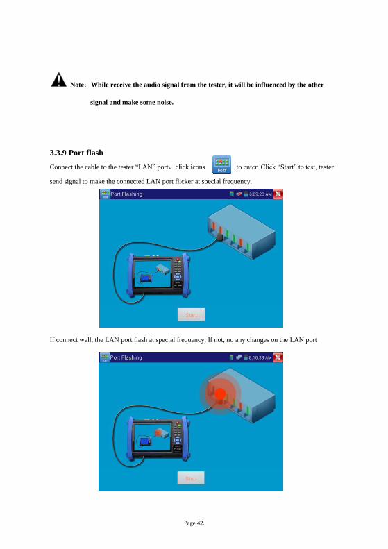
3.3.9 Port flash
Connect the cable to the tester “LAN” port,click icons to enter. Click “Start” to test, tester
send signal to make the connected LAN port flicker at special frequency.
If connect well, the LAN port flash at special frequency, If not, no any changes on the LAN port
Page.43.
Application:
The tester will send special signals to make the connected LAN port flicker at special frequency, which
will enable the installers to easily and quickly find the connected Ethernet cable. This function can
prevent mistakenly insertion or disconnection non-corresponding cable to artificially interrupt network
connection.
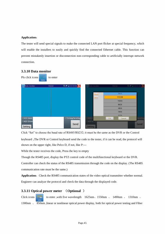
3.3.10 Data monitor
Pls click icons to enter
Click “Set” to choose the baud rate of RS485/RS232; it must be the same as the DVR or the Control
keyboard .The DVR or Control keyboard send the code to the tester, if it can be read, the protocol will
shown on the upper right, like Pelco D, if not, like P:---
While the tester receives the code, Press the key to empty
Though the RS485 port, display the PTZ control code of the multifunctional keyboard or the DVR.
Controller can check the status of the RS485 transmission through the code on the display. (The RS485
communication rate must be the same.)
Application:Check the RS485 communication states of the video optical transmitter whether normal.
Engineer can analyze the protocol and check the data through the displayed code.
3.3.11 Optical power meter (Optional )
Click icons to enter ,with five wavelength 1625nm、1550nm 、 1490nm 、 1310nm 、
1300nm 、 850nm ,linear or nonlinear optical power display, both for optical power testing and Fiber
Page.44.
link loss relative measurement . It is necessary tools for installation and maintenance optical fiber
communication, cable television and CCTV security system.
Note:Please keep the fiber connector and the dust cap be clean, and clean the detector with the special
alcohol.
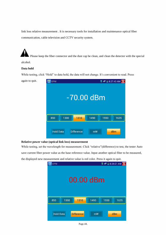
Data hold
While testing, click “Hold” to data hold, the data will not change. It’s convenient to read. Press
again to quit.
Relative power value (optical link loss) measurement
While testing, set the wavelength for measurement. Click “relative”(difference) to test, the tester Auto
save current fiber power value as the base reference value. Input another optical fiber to be measured,
the displayed new measurement and relative value is red color. Press it again to quit.

Page.45.
Data hold and Relative measuring use together, the data is yellow while the function is effect.
3.3.12 Visual Fault Locator(optional)
Click icons to enter

Page.46.
VFL four status can select——“Steady mode”, “Evasive 1Hz”,“Evasive 2Hz”and“Time off”. Click
button “Steady mode” to enter steady status, click button “Evasive 1Hz” and “Evasive 2Hz, to enter
pulse mode, click button “Time off”, VFL be turned off. Timed turn off can select (5mins, 10mins,
30mins, 60mins and 120mins).
Click” Steady mode”, red laser sources emit steady, click again to quit.
Click icons “Evasive 1Hz”or“Evasive 2Hz”to enter pulse mode, the red laser sources emitted by a
certain frequency, press it again to quit
Page.47.
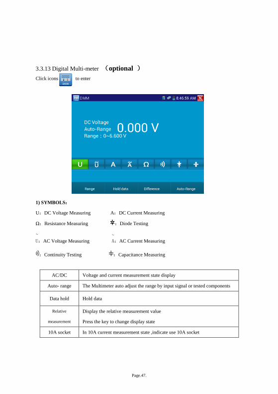
3.3.13 Digital Multi-meter (optional )
Click icons to enter
1) SYMBOLS:
U:DC Voltage Measuring A:DC Current Measuring
Ω:Resistance Measuring :Diode Testing
U~:AC Voltage Measuring A
~:AC Current Measuring
:Continuity Testing :Capacitance Measuring
AC/DC Voltage and current measurement state display
Auto- range The Multimeter auto adjust the range by input signal or tested components
Data hold Hold data
Relative
measurement
Display the relative measurement value
Press the key to change display state
10A socket In 10A current measurement state ,indicate use 10A socket
Page.48.
Over range The current measurement value over the range, if in the Auto range state, to
switch Auto.
2) OPERATING INSTRUCTION
A. DC Voltage Measuring
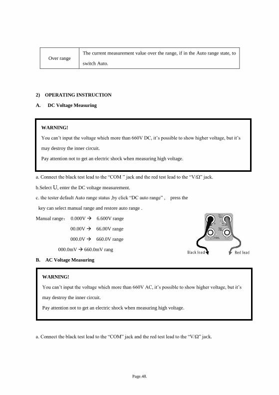
a. Connect the black test lead to the “COM ” jack and the red test lead to the “V/Ω” jack.
b.Select U, enter the DC voltage measurement.
c. the tester default Auto range status ,by click “DC auto range” , press the
key can select manual range and restore auto range .
Manual range: 0.000V 6.600V range
00.00V 66.00V range
000.0V 660.0V range
000.0mV 660.0mV rang
B. AC Voltage Measuring
a. Connect the black test lead to the “COM” jack and the red test lead to the “V/Ω” jack.
WARNING!
You can’t input the voltage which more than 660V DC, it’s possible to show higher voltage, but it’s
may destroy the inner circuit.
Pay attention not to get an electric shock when measuring high voltage.
WARNING!
You can’t input the voltage which more than 660V AC, it’s possible to show higher voltage, but it’s
may destroy the inner circuit.
Pay attention not to get an electric shock when measuring high voltage.
Page.49.
b. select U ~ , enter the AC voltage measurement.
C.the tester default Auto range status, by click “AC auto range”
d. Manual range can be select , press the key “NEAR” to restore Auto range
e.Manual range: 0.000V 6.600V range
00.00V 66.00V range
000.0V 660.0V range
000.0mV 660.0mV range
C. DC Current Measuring (only manual range )
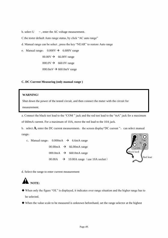
a. Connect the black test lead to the “COM ” jack and the red test lead to the “mA” jack for a maximum
of 660mA current. For a maximum of 10A, move the red lead to the 10A jack.
b.select A, enter the DC current measurement,the screen display“DC current ”,can select manual
range;
c.Manual range: 0.000mA 6.6mA range
00.00mA 66.00mA range
000.0mA 660.0mA range
00.00A 10.00A range(use 10A socket)
d. Select the range to enter current measurement
NOTE:
When only the figure “OL” is displayed, it indicates over range situation and the higher range has to
be selected.
When the value scale to be measured is unknown beforehand, set the range selector at the highest
WARNING!
Shut down the power of the tested circuit, and then connect the meter with the circuit for
measurement.

Page.50.
position.
The maximum current of mA socket is 660mA, over-current will destroy the fuse, and will damage
the meter.
The maximum current of 10A socket is 10A, over-current will destroy the meter, and will damage
the operator.
D. AC Current Measuring (Only Manual range)
a. Connect the black test lead to the “COM” jack and the red test lead to the“mA” jack for a maximum
of 660mA current. For a maximum of 10A, move the red lead to the 10A jack.
b. select A~
, enter the AC current measurement, manually select the range
c. Manual range: 0.000mA 6.600mA range
00.00mA 66.00mA range
000.0mA 660.0mA range
00.00A 10.00A range(use 10A socket)
Note:
When only the figure “OL” is displayed, it indicates over range situation and the higher range has to
be selected.
When the value scale to be measured is unknown beforehand, set the range selector at the highest
position.
The maximum current of mA socket is 660mA; over-current will destroy the fuse, and will damage
the meter.
WARNING!
Shut down the power of the tested circuit, and then connect the meter with the circuit for
measurement.
Page.51.
The maximum current of 10A socket is 10A, over-current will destroy the meter, and will damage
the operator.
In“ AC ” mode, only can input “AC ”, if not, will damage the meter.
E. Resistance Measuring
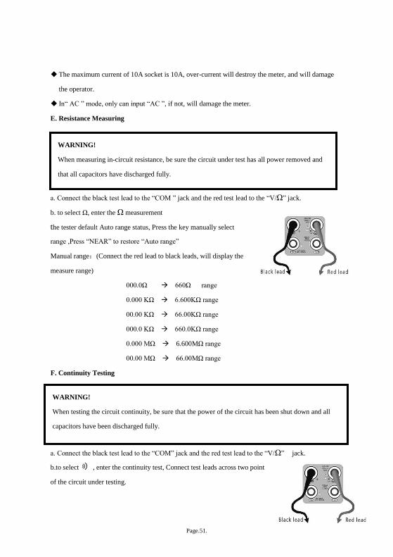
a. Connect the black test lead to the “COM ” jack and the red test lead to the “V/Ω” jack.
b. to select Ω, enter the Ω measurement
the tester default Auto range status, Press the key manually select
range ,Press “NEAR” to restore “Auto range”
Manual range:(Connect the red lead to black leads, will display the
measure range)
000.0Ω 660Ω range
0.000 KΩ 6.600KΩ range
00.00 KΩ 66.00KΩ range
000.0 KΩ 660.0KΩ range
0.000 MΩ 6.600MΩ range
00.00 MΩ 66.00MΩ range
F. Continuity Testing
a. Connect the black test lead to the “COM” jack and the red test lead to the “V/Ω” jack.
b.to select , enter the continuity test, Connect test leads across two point
of the circuit under testing.
WARNING!
When measuring in-circuit resistance, be sure the circuit under test has all power removed and
that all capacitors have discharged fully.
WARNING!
When testing the circuit continuity, be sure that the power of the circuit has been shut down and all
capacitors have been discharged fully.
Page.52.
c. If continuity exists (i.e., resistance less than about 50Ω), built-in buzzer will sound.
G. Diode Testing
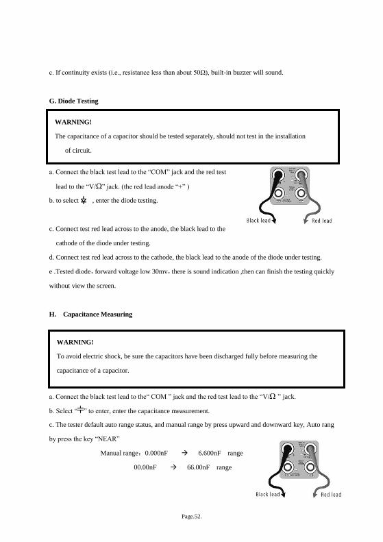
a. Connect the black test lead to the “COM” jack and the red test
lead to the “V/Ω” jack. (the red lead anode “+” )
b. to select , enter the diode testing.
c. Connect test red lead across to the anode, the black lead to the
cathode of the diode under testing.
d. Connect test red lead across to the cathode, the black lead to the anode of the diode under testing.
e .Tested diode,forward voltage low 30mv,there is sound indication ,then can finish the testing quickly
without view the screen.
H. Capacitance Measuring
a. Connect the black test lead to the“ COM ” jack and the red test lead to the “V/Ω ” jack.
b. Select “ ” to enter, enter the capacitance measurement.
c. The tester default auto range status, and manual range by press upward and downward key, Auto rang
by press the key “NEAR”
Manual range:0.000nF 6.600nF range
00.00nF 66.00nF range
WARNING!
The capacitance of a capacitor should be tested separately, should not test in the installation
of circuit.
WARNING!
To avoid electric shock, be sure the capacitors have been discharged fully before measuring the
capacitance of a capacitor.
Page.53.
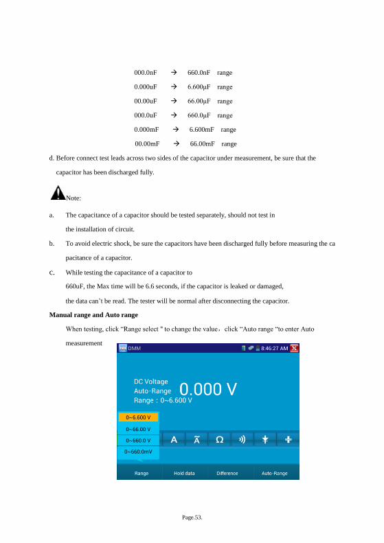
000.0nF 660.0nF range
0.000uF 6.600μF range
00.00uF 66.00μF range
000.0uF 660.0μF range
0.000mF 6.600mF range
00.00mF 66.00mF range
d. Before connect test leads across two sides of the capacitor under measurement, be sure that the
capacitor has been discharged fully.
Note:
a. The capacitance of a capacitor should be tested separately, should not test in
the installation of circuit.
b. To avoid electric shock, be sure the capacitors have been discharged fully before measuring the ca
pacitance of a capacitor.
c. While testing the capacitance of a capacitor to
660uF, the Max time will be 6.6 seconds, if the capacitor is leaked or damaged,
the data can’t be read. The tester will be normal after disconnecting the capacitor.
Manual range and Auto range
When testing, click “Range select " to change the value,click “Auto range “to enter Auto
measurement
Page.54.
Data hold
Click “Hold data” to enter, the data be hold, the value is green. Press it again to quit.
Relative value measurement
Click “Relative “to enter ,the tester Auto-save the data, the displayed new measurement and
relative value is red color. Press it again to quit
The hold function and the relative value be combined use, the display value is yellow
The meter protection
Voltage protection
You can’t input the voltage which more than 660V AC, it’s possible to show higher voltage, but
it’s may destroy the inner circuit.
Resistance、Continuity、Diode、PTC component Protection
Wrong input voltage,will Auto enter protection state , It only suitable for short and limit time work.
If input voltage over 600V, will damage the meter.
mA current fuse range :250V 1A
if the current over the rated range ,fuse will melt to protect the meter .Pls use the same model when
change the fuse, Pls opens the battery cover to change.
Note: 10A socket without fuse protection, if over the current range
Wrong using the 10A socket to measure the voltage, will damage the meter.
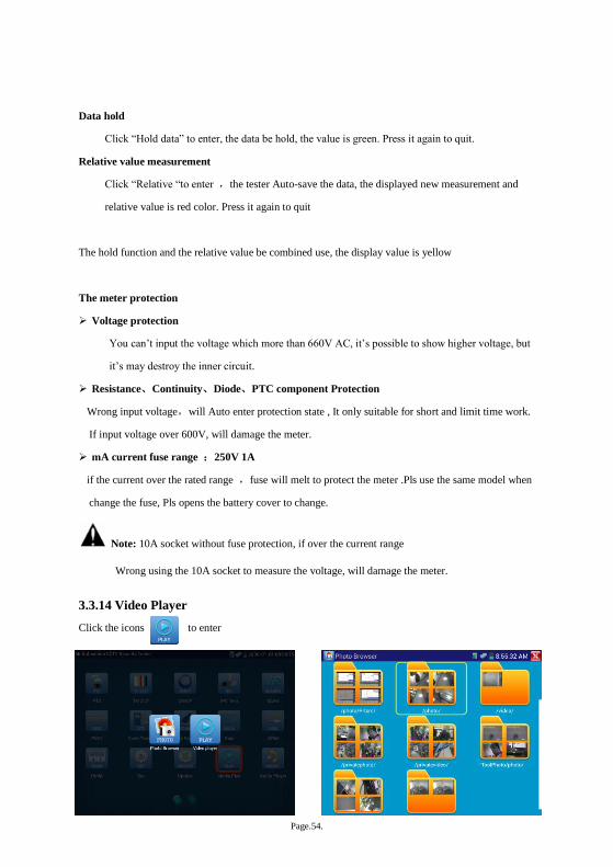
3.3.14 Video Player
Click the icons to enter
Page.55.
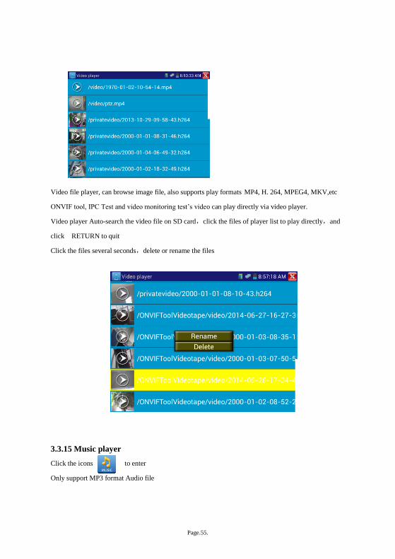
Video file player, can browse image file, also supports play formats MP4, H. 264, MPEG4, MKV,etc
ONVIF tool, IPC Test and video monitoring test’s video can play directly via video player.
Video player Auto-search the video file on SD card,click the files of player list to play directly,and
click RETURN to quit
Click the files several seconds,delete or rename the files
3.3.15 Music player
Click the icons to enter
Only support MP3 format Audio file
Page.56.
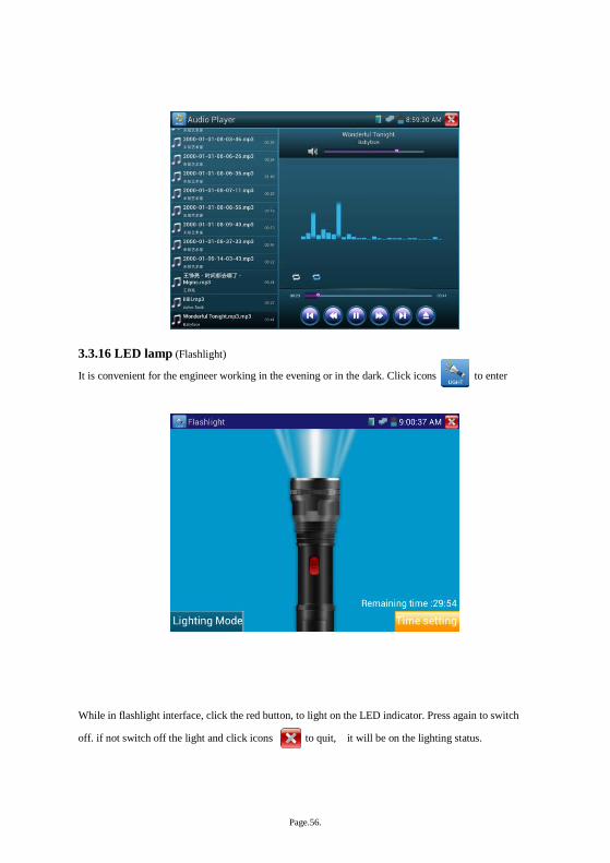
3.3.16 LED lamp (Flashlight)
It is convenient for the engineer working in the evening or in the dark. Click icons to enter
While in flashlight interface, click the red button, to light on the LED indicator. Press again to switch
off. if not switch off the light and click icons to quit, it will be on the lighting status.
Page.57.
Lighting model or Time setting can select.
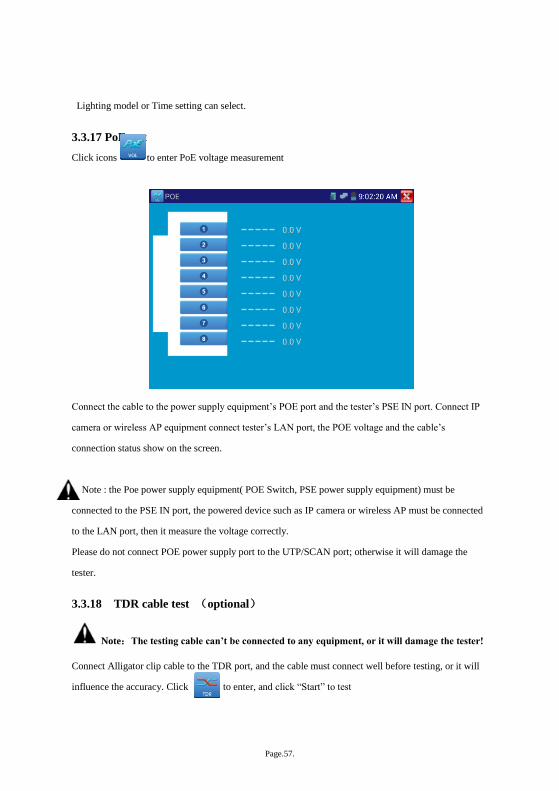
3.3.17 PoE test
Click icons to enter PoE voltage measurement
Connect the cable to the power supply equipment’s POE port and the tester’s PSE IN port. Connect IP
camera or wireless AP equipment connect tester’s LAN port, the POE voltage and the cable’s
connection status show on the screen.
Note : the Poe power supply equipment( POE Switch, PSE power supply equipment) must be
connected to the PSE IN port, the powered device such as IP camera or wireless AP must be connected
to the LAN port, then it measure the voltage correctly.
Please do not connect POE power supply port to the UTP/SCAN port; otherwise it will damage the
tester.
3.3.18 TDR cable test (optional)
Note:The testing cable can’t be connected to any equipment, or it will damage the tester!
Connect Alligator clip cable to the TDR port, and the cable must connect well before testing, or it will
influence the accuracy. Click to enter, and click “Start” to test
Page.58.
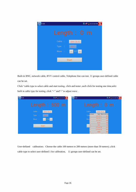
Built-in BNC, network cable, RVV control cable, Telephone line can test. 11 groups user-defined cable
can be set.
Click “cable type to select cable and start testing, click and tester ,each click for testing one time,selct
built in cable type for testing, click “+” and“-” to adjust wave .
User-defined calibration:Choose the cable 100 meters to 200 meters (more than 50 meters) ,click
cable type to select user-defined 1 for calibration, 11 groups user-defined can be set.
Page.59.
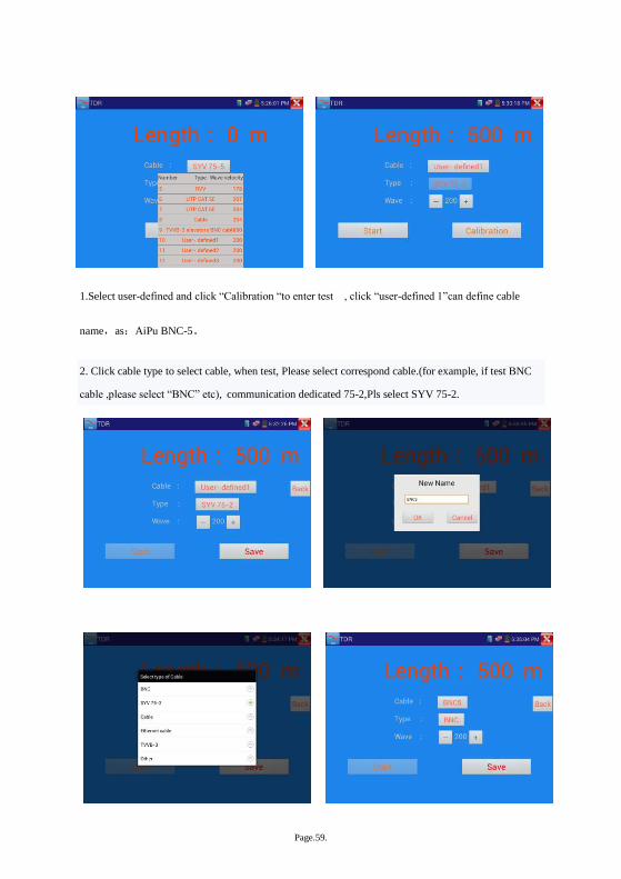
1.Select user-defined and click “Calibration “to enter test , click “user-defined 1”can define cable
name,as:AiPu BNC-5。
2. Click cable type to select cable, when test, Please select correspond cable.(for example, if test BNC
cable ,please select “BNC” etc), communication dedicated 75-2,Pls select SYV 75-2.
Page.60.
please select SYV 75-2
3.Click “+”or“-” to adjust wave speed ,while display length is the same as the actual
Length ,click “save “to save calibration data ,It can be used for the same cable testing after the
calibration.
Application:TDR test is the use of pulse reflection method, to transmit pulse signal for tested cable,
when cable is disconnected or short-circuited, reflected pulse generated, the tester receive and deal with
the reflected wave, measurement results displayed on the screen. TDR cable test can test cable length
and short circuit, help engineer quickly find the cable’s problem location. It is more convenient and
efficient to repair the faulty cable.
Note:The TDR reflect signal could be affected by the cable quality/ cable’s not well
connected etc to cause the different TDR measurement. The TDR measurement is for reference
only.
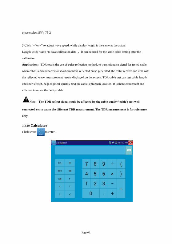
3.3.19 Calculator
Click icons to enter
Page.61.
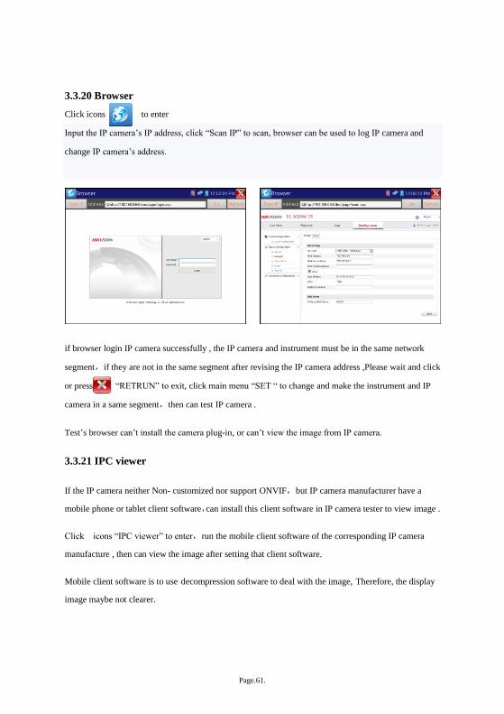
3.3.20 Browser
Click icons to enter
Input the IP camera’s IP address, click “Scan IP” to scan, browser can be used to log IP camera and
change IP camera’s address.
if browser login IP camera successfully , the IP camera and instrument must be in the same network
segment,if they are not in the same segment after revising the IP camera address ,Please wait and click
or press “RETRUN” to exit, click main menu “SET “ to change and make the instrument and IP
camera in a same segment,then can test IP camera .
Test’s browser can’t install the camera plug-in, or can’t view the image from IP camera.
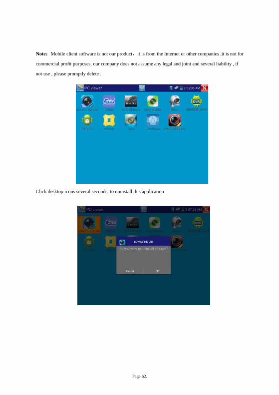
3.3.21 IPC viewer
If the IP camera neither Non- customized nor support ONVIF,but IP camera manufacturer have a
mobile phone or tablet client software,can install this client software in IP camera tester to view image .
Click icons “IPC viewer” to enter,run the mobile client software of the corresponding IP camera
manufacture , then can view the image after setting that client software.
Mobile client software is to use decompression software to deal with the image, Therefore, the display
image maybe not clearer.
Page.62.
Note:Mobile client software is not our product,it is from the Internet or other companies ,it is not for
commercial profit purposes, our company does not assume any legal and joint and several liability , if
not use , please promptly delete .
Click desktop icons several seconds, to uninstall this application
Page.63.
Click icons “update “ in the IPC viewer interface,to update Mobile client software.
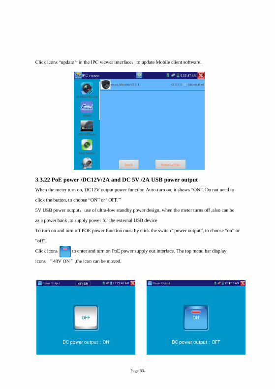
3.3.22 PoE power /DC12V/2A and DC 5V /2A USB power output
When the meter turn on, DC12V output power function Auto-turn on, it shows “ON”. Do not need to
click the button, to choose “ON” or “OFF.”
5V USB power output,use of ultra-low standby power design, when the meter turns off ,also can be
as a power bank ,to supply power for the external USB device
To turn on and turn off POE power function must by click the switch “power output”, to choose “on” or
“off”.
Click icons to enter and turn on PoE power supply out interface. The top menu bar display
icons “48V ON”,the icon can be moved.

Page.64.
Note:
1 .Don’t input any power into the “DC12/2A OUTPUT” port of the CCTV tester to avoid destroy.
2. Don’t output this DC12V/2A power to the power input port of the CCTV tester to avoid destroy
3. When the requirement of the camera is higher than 2A, the CCTV tester will enter protection mode.
Disconnect all the connections of the CCTV tester and then connect the CCTV tester with power
adaptor to resume the CCTV tester.
4. Before turn on the power output, Please make sure the IP camera support PoE powered. Otherwise
damage IP camera.
5. When use PoE output, UTP cable must be Straight-through, and cannot short-circuited, or it will
damage the instrument!
6. Make sure the tester is full charged or more than 80%, or it will shows low power and cannot
supply power.
3.3.23 Application tools
It contains audio record, network bandwidth test tools now .Some application tools can customize
according customer’s requirements.
Click icons to enter
Page.65.
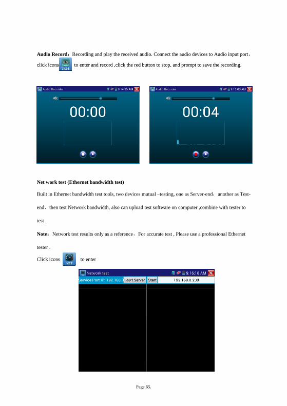
Audio Record:Recording and play the received audio. Connect the audio devices to Audio input port,
click icons to enter and record ,click the red button to stop, and prompt to save the recording.
Net work test (Ethernet bandwidth test)
Built in Ethernet bandwidth test tools, two devices mutual –testing, one as Server-end,another as Test-
end,then test Network bandwidth, also can upload test software on computer ,combine with tester to
test .
Note:Network test results only as a reference,For accurate test , Please use a professional Ethernet
tester .
Click icons to enter
Page.66.
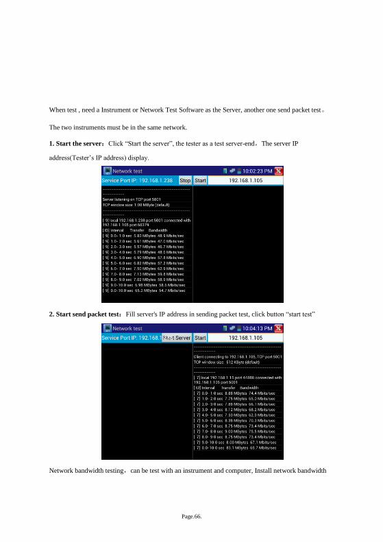
When test , need a Instrument or Network Test Software as the Server, another one send packet test。
The two instruments must be in the same network.
1. Start the server:Click “Start the server”, the tester as a test server-end,The server IP
address(Tester’s IP address) display.
2. Start send packet test:Fill server's IP address in sending packet test, click button “start test”
Network bandwidth testing,can be test with an instrument and computer, Install network bandwidth
Page.67.
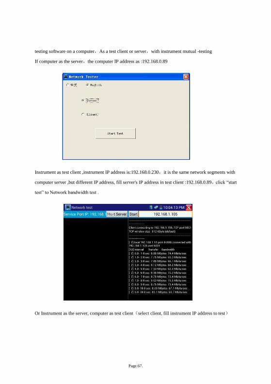
testing software on a computer,As a test client or server,with instrument mutual -testing
If computer as the server,the computer IP address as :192.168.0.89
Instrument as test client ,instrument IP address is:192.168.0.230,it is the same network segments with
computer server ,but different IP address, fill server's IP address in test client :192.168.0.89,click “start
test” to Network bandwidth test .
Or Instrument as the server, computer as test client(select client, fill instrument IP address to test)
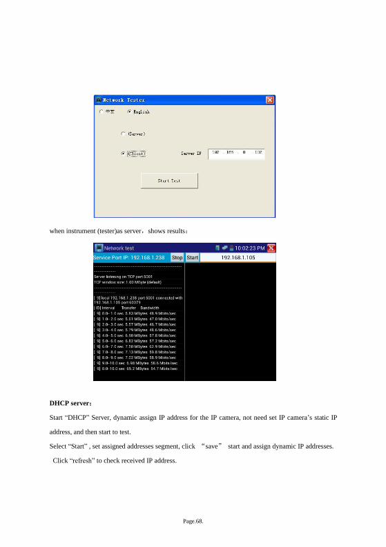
Page.68.
when instrument (tester)as server,shows results:
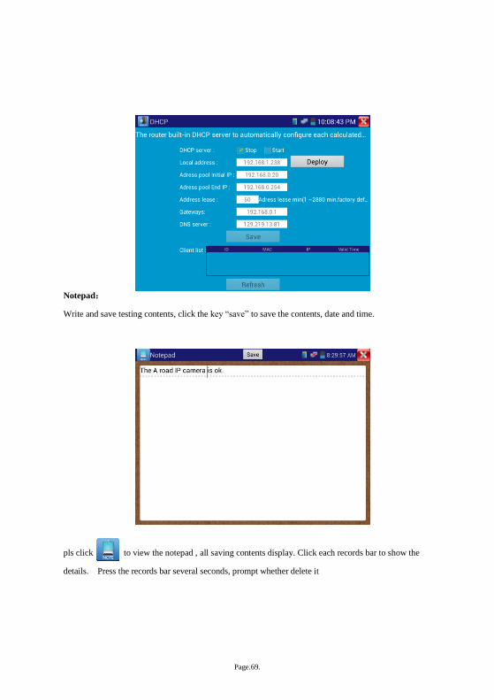
DHCP server:
Start “DHCP” Server, dynamic assign IP address for the IP camera, not need set IP camera’s static IP
address, and then start to test.
Select “Start” , set assigned addresses segment, click “save” start and assign dynamic IP addresses.
Click “refresh” to check received IP address.
Page.69.
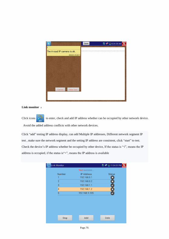
Notepad:
Write and save testing contents, click the key “save” to save the contents, date and time.
pls click to view the notepad , all saving contents display. Click each records bar to show the
details. Press the records bar several seconds, prompt whether delete it
Page.70.
Link monitor :
Click icons to enter, check and add IP address whether can be occupied by other network device.
Avoid the added address conflicts with other network devices.
Click “add” testing IP address display, can add Multiple IP addresses, Different network segment IP
test , make sure the network segment and the setting IP address are consistent, click “start” to test.
Check the device’s IP address whether be occupied by other device, If the status is “√”, means the IP
address is occupied, if the status is“×”, means the IP address is available

Page.71.
Application:
Add an IP camera or other network device to the current network group, the new IP address must not be
occupied, otherwise it will cause IP conflicts and stop the equipment normal working. Link monitor can
check if the new setting IP address is occupied.
3.3.24 APPS Tools
Click icons to enter
user can move menu Icons into APP Tool, click Icons several seconds,prompt whether move the icon
to APPS tool .
Click icons “APPS” to show all icons, if click other areas range (without icons area) to return menu.
Click icons several seconds, prompt whether move the icon to the main menu.
Page.72.
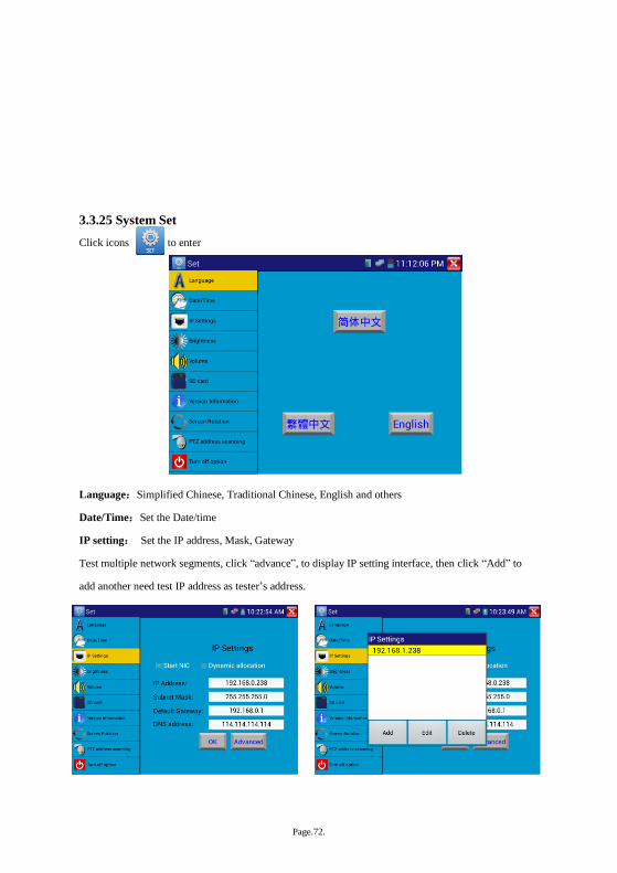
3.3.25 System Set
Click icons to enter
Language:Simplified Chinese, Traditional Chinese, English and others
Date/Time:Set the Date/time
IP setting: Set the IP address, Mask, Gateway
Test multiple network segments, click “advance”, to display IP setting interface, then click “Add” to
add another need test IP address as tester’s address.
Page.73.
After setting IP address (ref above pictures), it can test two network segments IP camera
(192.168.0.0and) 192.168.1.0.
WIFI:Turn on /Turn off wifi
Brightness:Set brightness、sleep time(15-30 seconds, or brightness).
Volume:Set volume
SD Card:Show SD Card Capacity, unmount SD card
Power display: display the battery level information
Version information:Check version information for each application
PTZ address scan: Turn on/ off
Screen rotation:Image 180 degree rotation, the power output port and network port will be on
the top to easy connect and operate.
PTZ address scan :Turn on it, then enter “Video monitor” interface to operate , after exit “Video
monitor” ,PTZ address scan will Auto-turn off .
Turn off option:Fast turn off .When select it ,the tester running fast and enter main menu. Some data
is not refreshed and clear, to avoid smaller problem, please do not use “Fast turn off” the tester.
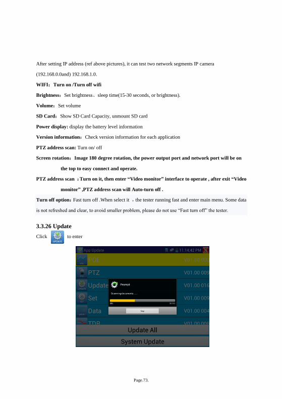
3.3.26 Update
Click to enter
Page.74.
If could update, it will appear in the update application interface, click relative program to update the
new version
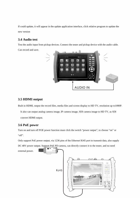
3.4 Audio test
Test the audio input from pickup devices. Connect the tester and pickup device with the audio cable.
Can record and save.
3.5 HDMI output
Built in HDMI, output the record files, media files and screen display to HD TV, resolution up to1080P.
It also can output analog camera image, IP camera image, SDI camera image to HD TV, as SDI
convert HDMI output.
3.6 PoE power
Turn on and turn off POE power function must click the switch “power output”, to choose “on” or
“off”.
Only support PoE power output, via 1236 pins of the Ethernet RJ45 port to transmit data, also supply
DC 48V power output. Support PoE PD camera, can directly connect it to the tester, and no need
external power.
Page.75.
Notice
a. The connected UTP cable must be Straight-through, and cannot short-circuited, or it will damage the
instrument!
b. Before using PoE power output, Pls check the IP camera whether support POE powered. Otherwise
it will damage the IP camera.
The instrument’s PoE maximum power output is 24W. If Ultra- high-power loads, the tester will enter
self-protection status.
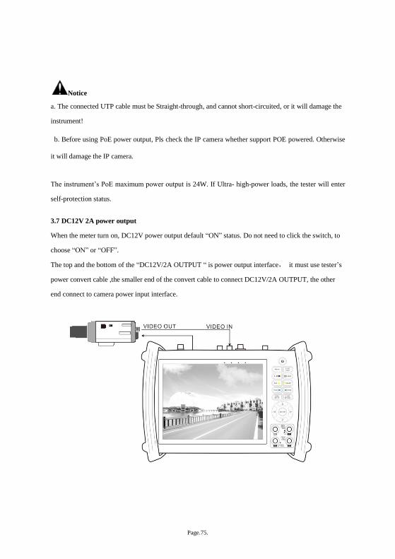
3.7 DC12V 2A power output
When the meter turn on, DC12V power output default “ON” status. Do not need to click the switch, to
choose “ON” or “OFF”.
The top and the bottom of the “DC12V/2A OUTPUT “ is power output interface, it must use tester’s
power convert cable ,the smaller end of the convert cable to connect DC12V/2A OUTPUT, the other
end connect to camera power input interface.
Page.76.
Application
Power output functions mainly used in the camera field demonstration and testing, meanwhile, for some
camera installation area, if there is no power adaptor, it can as temporary power to supply power for the
camera.
Notice:
a. Prohibits connect any external power to the tester‘s DC12V/2A OUTPUT port , or the tester and
external power will damage .it is not within the Company 's warranty.
b. Prohibited DC12V / 2A power output to the instrument’s INPUT DC12V power input port,
otherwise the tester will damage, and man-made damage is not within the Company’s warranty.
c. The Tester’s output current near 2 A, When camera current is higher than 2A, the tester will enter
self-protection status. Disconnect the instrument's power output adapter cable, use the charger to
charge the instrument, can release the protection.
d. Make sure the tester is full charged or more than 3 bars; otherwise it will be short circuit.
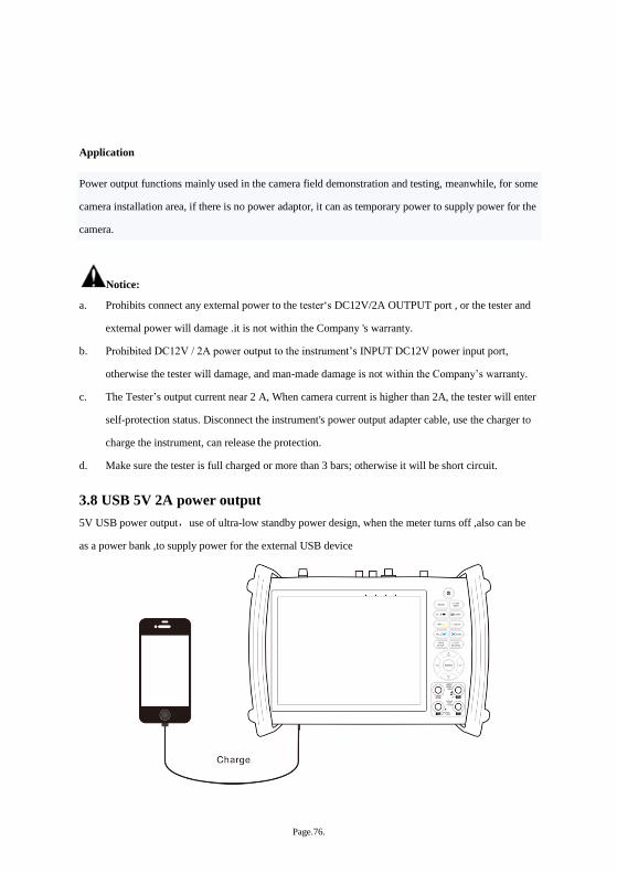
3.8 USB 5V 2A power output
5V USB power output,use of ultra-low standby power design, when the meter turns off ,also can be
as a power bank ,to supply power for the external USB device

Page.77.
4. Specifications
4.1 General Specifications
Model IPC-8600【T】models optional
Display 7 inch Capacitive touch screen , resolution 800(RGB)x 600
Network port 10/100M auto adjust,RJ45
WIFI Built in WIFI,speeds150M,receive wireless camera image etc
IP camera type
ONVIF,ACTi、Dahua IPC-HFW2100P、Hikvision,DS-2CD864-E13、Samsung
SNZ-5200、Tiandy TD-NC9200S2、Kodak IPC120L、Honeywell HICC-2300T、
Aipu-waton IP5000-BC-13MP/IRS06-13MP、fine-Tida IPC、FSJ BY-1080Q、WEISKY
IPC camera etc. Customized welcome
Video level test 1 channel BNC Input & 1 channel Output , NTSC/PAL (Auto adapt)
Video level meter
PEAK video signal level, SYNC signal level, COLOR BURST chroma level
measurement
Zoom Image Support Analog camera and IP camera image zoom /move
Snapshots, Video
record, Record
playback
Image Screenshots, record ,save ,view and record play back
HDMI output 1 channel HDMI output,support 1920*1080P
12V/2A power output Output DC12V/2A power for camera
USB 5V power output 5V 2A power output,as a mobile phone power bank
PoE power output 48V PoE power output,Max power 24W
Audio test 1 channel audio signal input, test whether sound normal, 1 channel audio
signal, to connect headphone
PTZ control
Support RS232/RS485 control, Baud 600-115200bps, Compatible with
more than 30 protocols such as PELCO-D/P, Samsung, Panasonic, Lilin,
Yaan, etc
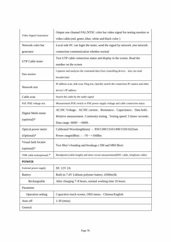
Page.78.
Video Signal Generation Output one channel PAL/NTSC color bar video signal for testing monitor or
video cable.(red, green ,blue, white and black color )
Network color bar
generator
Local side PC can login the tester, send the signal by network ,test network
connection communication whether normal
UTP Cable tester Test UTP cable connection status and display in the screen. Read the
number on the screen
Data monitor
Captures and analyzes the command data from controlling device,also can send
hexadecimal
Network test IP address scan, link scan, Ping test, Quickly search the connection IP camera and other
device’s IP address
Cable scan Search the cable by the audio signal
PoE /PSE voltage test Measurement POE switch or PSE power supply voltage and cable connection status
Digital Multi-meter
(optional)*
AC/DC Voltage,AC/DC current、Resistance、Capacitance、Data hold、
Relative measurement、Continuity testing . Testing speed: 3 times/ seconds,
Data range -6600~+6600.
Optical power meter
(Optional)*
Calibrated Wavelength(nm) :850/1300/1310/1490/1550/1625nm
Power range(dBm) :-70~+10dBm
Visual fault locator
(optional)* Test fiber’s bending and breakage ( SM and MM fiber)
TDR cable test(optional) * Breakpoint (cable length) and short circuit measurement(BNC cable, telephone cable)
POWER
External power supply DC 12V 2A
Battery Built-in 7.4V Lithium polymer battery ,6500mAh
Rechargeable After charging 7~8 hours, normal working time 16 hours
Parameter
Operation setting Capacitive touch screen, OSD menu,Chinese/English
Auto off 1-30 (mins)
General
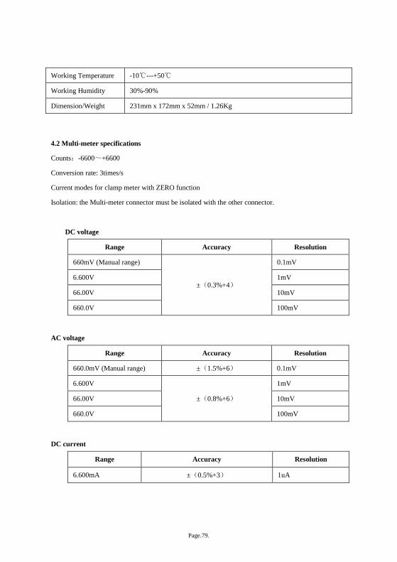
Page.79.
Working Temperature -10℃---+50℃
Working Humidity 30%-90%
Dimension/Weight 231mm x 172mm x 52mm / 1.26Kg
4.2 Multi-meter specifications
Counts:-6600~+6600
Conversion rate: 3times/s
Current modes for clamp meter with ZERO function
Isolation: the Multi-meter connector must be isolated with the other connector.
DC voltage
Range Accuracy Resolution
660mV (Manual range)
±(0.3%+4)
0.1mV
6.600V 1mV
66.00V 10mV
660.0V 100mV
AC voltage
Range Accuracy Resolution
660.0mV (Manual range) ±(1.5%+6) 0.1mV
6.600V
±(0.8%+6)
1mV
66.00V 10mV
660.0V 100mV
DC current
Range Accuracy Resolution
6.600mA ±(0.5%+3) 1uA
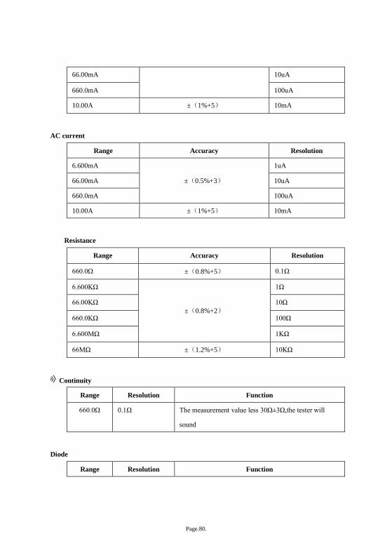
Page.80.
66.00mA 10uA
660.0mA 100uA
10.00A ±(1%+5) 10mA
AC current
Range Accuracy Resolution
6.600mA
±(0.5%+3)
1uA
66.00mA 10uA
660.0mA 100uA
10.00A ±(1%+5) 10mA
Resistance
Range Accuracy Resolution
660.0Ω ±(0.8%+5) 0.1Ω
6.600KΩ
±(0.8%+2)
1Ω
66.00KΩ 10Ω
660.0KΩ 100Ω
6.600MΩ 1KΩ
66MΩ ±(1.2%+5) 10KΩ
Continuity
Range Resolution Function
660.0Ω 0.1Ω The measurement value less 30Ω±3Ω,the tester will
sound
Diode
Range Resolution Function
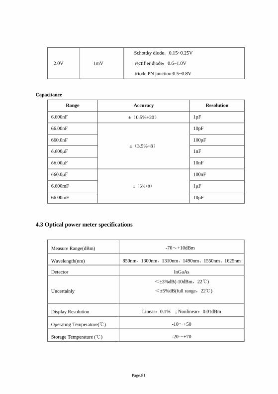
Page.81.
2.0V
1mV
Schottky diode:0.15~0.25V
rectifier diode:0.6~1.0V
triode PN junction:0.5~0.8V
Capacitance
Range Accuracy Resolution
6.600nF ±(0.5%+20) 1pF
66.00nF
±(3.5%+8)
10pF
660.0nF 100pF
6.600μF 1nF
66.00μF 10nF
660.0μF
±(5%+8)
100nF
6.600mF 1μF
66.00mF 10μF
4.3 Optical power meter specifications
Measure Range(dBm) -70~+10dBm
Wavelength(nm) 850nm、1300nm、1310nm、1490nm、1550nm、1625nm
Detector InGaAs
Uncertainly
<±3%dB(-10dBm,22℃)
<±5%dB(full range,22℃)
Display Resolution Linear:0.1% ; Nonlinear:0.01dBm
Operating Temperature(℃) -10~+50
Storage Temperature (℃) -20~+70
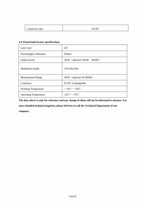
Page.82.
Connector type FC/PC
4.4 Visual fault locator specifications
Laser type LD
Wavelength Calibration 650nm
Output power 5mW(optional 10mW,20mW)
Modulation mode CW/1Hz/2Hz
Measurement Range 5KM(optional 10-20KM)
Connector FC/PC exchangeable
Working Temperature -10℃~+50℃
Operating Temperature -20℃~+70℃
The data above is only for reference and any change of them will not be informed in advance. For
more detailed technical inquiries, please feel free to call the Technical Department of our
company.