is 16102-1 (2012): self - ballasted led lamps for general
TRANSCRIPT
Disclosure to Promote the Right To Information
Whereas the Parliament of India has set out to provide a practical regime of right to information for citizens to secure access to information under the control of public authorities, in order to promote transparency and accountability in the working of every public authority, and whereas the attached publication of the Bureau of Indian Standards is of particular interest to the public, particularly disadvantaged communities and those engaged in the pursuit of education and knowledge, the attached public safety standard is made available to promote the timely dissemination of this information in an accurate manner to the public.
इटरनट मानक
“!ान $ एक न' भारत का +नम-ण”Satyanarayan Gangaram Pitroda
“Invent a New India Using Knowledge”
“प0रा1 को छोड न' 5 तरफ”Jawaharlal Nehru
“Step Out From the Old to the New”
“जान1 का अ+धकार, जी1 का अ+धकार”Mazdoor Kisan Shakti Sangathan
“The Right to Information, The Right to Live”
“!ान एक ऐसा खजाना > जो कभी च0राया नहB जा सकता ह”Bhartṛhari—Nītiśatakam
“Knowledge is such a treasure which cannot be stolen”
“Invent a New India Using Knowledge”
ह”ह”ह
IS 16102-1 (2012): Self - Ballasted LED Lamps for GeneralLighting Services, Part 1: Safety Requirements [ETD 23:Electric Lamps and their Auxiliaries]

© BIS 2012
B U R E A U O F I N D I A N S T A N D A R D SMANAK BHAVAN, 9 BAHADUR SHAH ZAFAR MARG
NEW DELHI 110002
February 2012 Price Group 6
IS 16102 (Part 1) : 2012
Hkkjrh; ekud
lkekU; izdk'k lsokvksa ds fy, Lor% tyus okys,y bZ Mh ySEiHkkx 1 lqjkk viskk,¡
Indian Standard
SELF-BALLASTED LED LAMPS FOR GENERALLIGHTING SERVICESPART 1 SAFETY REQUIREMENTS
ICS 29.140.99
Electric Lamps and Their Auxiliaries Sectional Committee, ETD 23
FOREWORD
This Indian Standard (Part 1) was adopted by the Bureau of Indian Standards, after the draft finalized by theElectric Lamps and Their Auxiliaries Sectional Committee had been approved by the Electrotechnical DivisionCouncil.
This standard specifies the general and safety requirements for self-ballasted lamps for general lighting servicesfor d.c. supplies up to 250 V or a.c. supplies up to 1 000 V at 50 Hz.
The performance requirements have been covered in Part 2 of this standard.
This standard is published in two parts. The other part in the series is:
Part 2 Performance requirements
There are already LED products in the market which substitute existing lamps, either as retrofit mains voltageincandescent or self-ballasted fluorescent lamps or as replacement for tungsten halogen lamps below 50 V.
Future work will also consequently comprise performance standards for all kind of LED lamps, including minimumphotometric requirements for type testing.
This standard is based on IEC 62560 : 2011 ‘Self-ballasted LED lamps for general lighting services by voltageabove 50 V — Safety specifications’, issued by the International Electrotechnical Commission (IEC) with thefollowing modifications:
a) Made applicable for d.c. supplies up to 250 V or a.c. supplies up to 1 000 V at 50 Hz;b) Schedule of type test and acceptance test has been incorporated;
c) Selection of samples incorporated;
d) Conditions of compliances incorporated; ande) Marking of rated lumen and danger symbol on high temperature added.
For the purpose of deciding whether a particular requirement of this standard is complied with, the final value,observed or calculated expressing the result of a test or analysis, shall be rounded off in accordance with IS 2 : 1960‘Rules for rounding off numerical values (revised)’. The number of significant places retained in the rounded offvalue should be the same as that of the specified value in this standard.
1
IS 16102 (Part 1) : 2012
Indian Standard
SELF-BALLASTED LED LAMPS FOR GENERALLIGHTING SERVICESPART 1 SAFETY REQUIREMENTS
1 SCOPE
This standard (Part 1) specifies the safety andinterchangeability requirements, together with the testmethods and conditions, required to show complianceof LED lamps with integrated means for stableoperation (self-ballasted LED lamps), intended fordomestic and similar general lighting purposes, having,
a) a rated wattage up to 60 W;
b) a rated voltage of d.c. supplies up to 250 V ora.c. supplies up to 1 000 V at 50 Hz; and
c) caps according to Table 1.
Recommendations for batch testing are given in AnnexC of IS 16103 (Part 1) : 2012 ‘LED modules for generallighting: Part 1 Safety requirements’.
NOTES
1 Where in this standard the term “lamp(s)” is used, it isunderstood to stand for “self-ballasted LED lamp(s)”, exceptwhere it is obviously assigned to other types of lamps.
2 Higher wattage lamp is under consideration.
Annex A provides an overview of systems composedof LED system and control gear.
2 REFERENCES
The standards listed below contain provisions which,through reference in this text, constitute provisions ofthis standard. At the time of publication, the editionsindicated were valid. All standards are subject torevision and parties to agreements based on thisstandard are encouraged to investigate the possibilityof applying the most recent editions of the standardslisted as follows:
IS No. Title
4261 : 2001 Glossary of terms relating to paperand pulp based packaging materials
8913 : 1978 Standard method of measurement oflamp cap temperature rise
9206 : 1979 Dimensions of caps for tungstenfilament general service electriclamps
10322 (Part 1) : Luminaires: Part 1 General2011 requirements and tests
11000 (Part 2/ Fire hazard testing: Part 2 TestSec 1) : 2008 method, Section 1 Glow-wire
IS No. Title
apparatus and common testprocedure
12063 : 1987 Classification of degrees ofprotection provided by enclosures ofelectrical equipment
15518 (Part 1) : Safety requirements for incandescent2004 lamps: Part 1 Tungsten filament
lamps for domestic and similargeneral lighting purposes
15687 (Part 1) : Single-capped fluorescent lamps:2006 Part 1 Safety requirements
15885 (Part 1) : Safety of lamp controlgear: Part 12011 General requirements
16101 : 2012 Terms and definitions of LEDs andLED modules in general lighting
16102 (Part 2) : Self-ballasted LED lamps for general2012 lighting services: Part 2 Performance
requirements16103 (Part 1) : LED modules for general lighting:
2012 Part 1 Safety requirements16108 : 2012 Photobiological safety of LED and
LED systems
3 TERMINOLOGY
For the purpose of this standard the definitions givenin IS 16103 (Part 1) and IS 16101 along with thefollowing shall apply.
3.1 Self-Ballasted LED Lamp — Unit which cannotbe dismantled without being permanently damaged,provided with a lamp cap and incorporating a LEDlight source and any additional elements necessary forstable operation of the light source.
NOTE — Lamp caps are given in IS 9206 .
3.2 Type — Lamps that, independent of the type ofcap or base, have an identical photometric and electricalrating.
3.3 Rated Voltage — Voltage or voltage range markedon the lamp.
3.4 Rated Wattage — Wattage marked on the lamp.
3.5 Rated Frequency — Frequency marked on thelamp.
3.6 Cap Temperature Rise (∆∆∆∆∆ ts) — Surface
2
IS 16102 (Part 1) : 2012
temperature rise (above ambient) of a standard testlampholder fitted to the lamp, when measured inaccordance with the standard method, in case of anEdison screw cap or a bayonet cap.
NOTE — The standard method for Edison screw cap or Bayonetcap is given in IS 8913.
3.7 Live Part — Conductive part which may cause anelectric shock in normal use.
3.8 Type Test — A test or series of tests made on atype test sample for the purpose of checkingcompliance of the design of a given product with therequirements of the relevant standard.
3.9 Type Test Sample — A sample consisting of oneor more similar units submitted by the manufactureror responsible vendor for the purpose of the type test.
3.10 Acceptance Test — Tests carried out on samplestaken from a lot for the acceptance of the lot.
3.11 Inspection Test Quantity (ITQ) — The numberof lamps selected for the purpose of determining theacceptability of a batch as to marking,interchangeability, protection against electric shock,insulation resistance, electric strength, mechanicalstrength, cap temperature rise, resistance to heat,resistance to flame and ignition, fault conditions andcreepage distances and clearances.
3.12 Batch — All the lamps of one type put forward atone time for acceptance test.
4 GENERAL REQUIREMENT AND GENERALTEST REQUIREMENTS
4.1 The lamps shall be so designed and constructedthat in normal use they function reliably and cause nodanger to the user or surroundings.
In general, compliance is checked by carrying out allthe tests specified.
4.2 Self-Ballasted LED
Lamps are non-repairable, factory-sealed units. Theyshall normally not be opened for any tests. In the caseof doubt based on the inspection of the lamp and theexamination of the circuit diagram, and in agreementwith the manufacturer or responsible vendor, either theoutput terminals shall be short-circuited or, inagreement with the manufacturer, lamps speciallyprepared so that a fault condition can be simulated shallbe submitted for testing (see 13).
4.3 In general, all tests are carried out on each type oflamp or, where a range of similar lamps is involved, foreach wattage in the range or on a representative selectionfrom the range, as agreed with the manufacturer.
4.4 When the lamp fails safely during one of the tests,it is replaced, provided that no fire, smoke or flammablegas is produced. Further requirements on failing safeare given in 12.
5 MARKING
5.1 Lamps shall be clearly and durably marked withthe following mandatory markings:
a) Mark of origin (this may take the form of atrade-mark, the manufacturer’s name or thename of the responsible vendor);
b) Rated voltage or voltage range (marked ‘V’or ‘Volt’);
c) Rated wattage (marked ‘W’ or ‘Watts’);
d) Rated lumen;
e) Rated frequency (marked in ‘Hz’);
f) Country of manufacture; and
g) Mark of symbol on high temperature.
5.2 In addition, the following information shall be givenby the lamp manufacturer on the lamp or immediate lampwrapping or container or in installation instructions:
a) Burning position, if restricted, shall be markedwith the appropriate symbol. Symbolexamples are shown in Annex B.
b) Rated current (marked ‘A’ or ‘ampere’).
c) For lamps with a weight significantly higherthan that of the lamps for which they are areplacement, attention should be drawn to thefact that the increased weight may reduce themechanical stability of certain luminaires andlampholders and may impair contact makingand lamp retention.
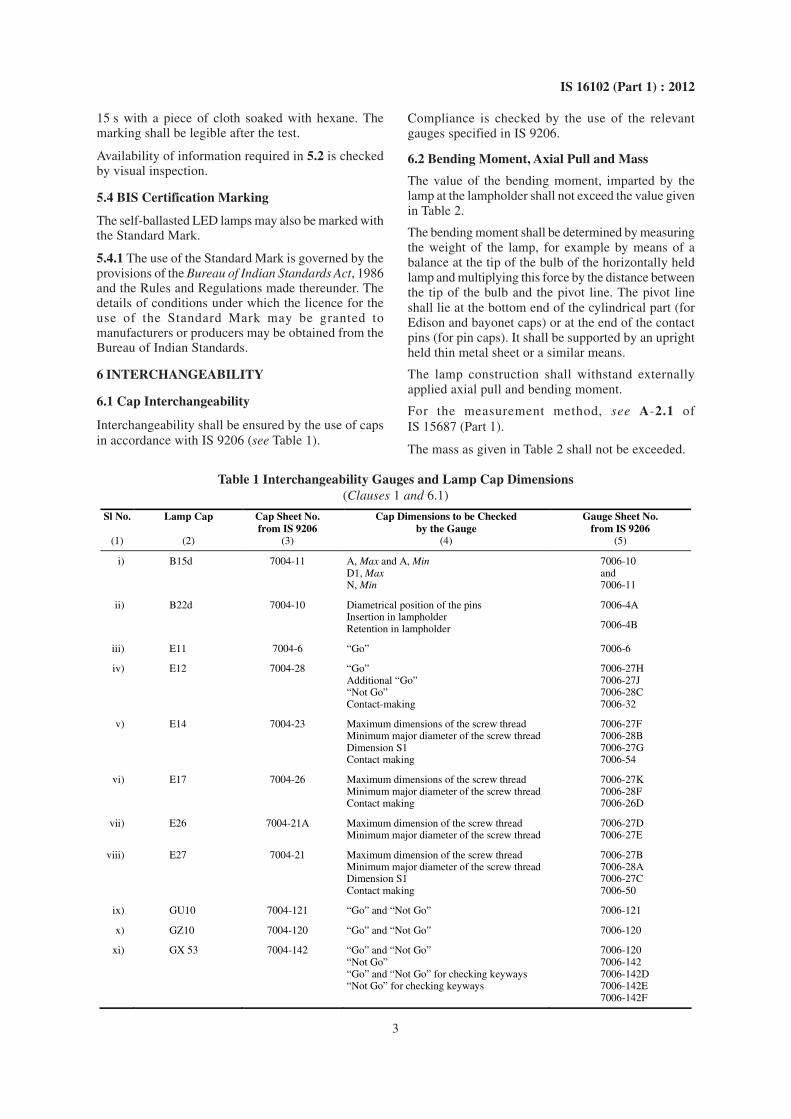
d) Special conditions or restrictions which shallbe observed for lamp operation, for exampleoperation in dimming circuits. Where lampsare not suitable for dimming, the followingsymbol in Fig. 1 may be used.
e) For eye protection, see requirements ofIS 16108.
FIG. 1 DIMMING NOT ALLOWED
5.3 Compliance is checked by the following:
Presence and legibility of the marking required in 5.1shall be checked by visual inspection.
The durability of the marking is checked by trying toremove it by rubbing lightly for 15 s with a piece ofcloth soaked with water and, after drying, for a further
3
IS 16102 (Part 1) : 2012
15 s with a piece of cloth soaked with hexane. Themarking shall be legible after the test.
Availability of information required in 5.2 is checkedby visual inspection.
5.4 BIS Certification Marking
The self-ballasted LED lamps may also be marked withthe Standard Mark.
5.4.1 The use of the Standard Mark is governed by theprovisions of the Bureau of Indian Standards Act, 1986and the Rules and Regulations made thereunder. Thedetails of conditions under which the licence for theuse of the Standard Mark may be granted tomanufacturers or producers may be obtained from theBureau of Indian Standards.
6 INTERCHANGEABILITY
6.1 Cap Interchangeability
Interchangeability shall be ensured by the use of capsin accordance with IS 9206 (see Table 1).
Compliance is checked by the use of the relevantgauges specified in IS 9206.
6.2 Bending Moment, Axial Pull and Mass
The value of the bending moment, imparted by thelamp at the lampholder shall not exceed the value givenin Table 2.
The bending moment shall be determined by measuringthe weight of the lamp, for example by means of abalance at the tip of the bulb of the horizontally heldlamp and multiplying this force by the distance betweenthe tip of the bulb and the pivot line. The pivot lineshall lie at the bottom end of the cylindrical part (forEdison and bayonet caps) or at the end of the contactpins (for pin caps). It shall be supported by an uprightheld thin metal sheet or a similar means.
The lamp construction shall withstand externallyapplied axial pull and bending moment.
For the measurement method, see A-2.1 ofIS 15687 (Part 1).
The mass as given in Table 2 shall not be exceeded.
Table 1 Interchangeability Gauges and Lamp Cap Dimensions(Clauses 1 and 6.1)
Sl No. Lamp Cap Cap Sheet No. from IS 9206
Cap Dimensions to be Checked by the Gauge
Gauge Sheet No. from IS 9206
(1) (2) (3) (4) (5)
i) B15d 7004-11 A, Max and A, Min D1, Max N, Min
7006-10 and 7006-11
ii) B22d 7004-10 Diametrical position of the pins Insertion in lampholder Retention in lampholder
7006-4A
7006-4B
iii) E11 7004-6 “Go” 7006-6
iv) E12 7004-28 “Go” Additional “Go” “Not Go” Contact-making
7006-27H 7006-27J 7006-28C 7006-32
v) E14 7004-23 Maximum dimensions of the screw thread Minimum major diameter of the screw thread Dimension S1 Contact making
7006-27F 7006-28B 7006-27G 7006-54
vi) E17 7004-26 Maximum dimensions of the screw thread Minimum major diameter of the screw thread Contact making
7006-27K 7006-28F 7006-26D
vii) E26 7004-21A Maximum dimension of the screw thread Minimum major diameter of the screw thread
7006-27D 7006-27E
viii) E27 7004-21 Maximum dimension of the screw thread Minimum major diameter of the screw thread Dimension S1 Contact making
7006-27B 7006-28A 7006-27C 7006-50
ix) GU10 7004-121 “Go” and “Not Go” 7006-121
x) GZ10 7004-120 “Go” and “Not Go” 7006-120
xi) GX 53 7004-142 “Go” and “Not Go” “Not Go” “Go” and “Not Go” for checking keyways “Not Go” for checking keyways
7006-120 7006-142 7006-142D 7006-142E 7006-142F
4
IS 16102 (Part 1) : 2012
Table 2 Bending Moment and Masses(Clause 6.2)
Sl No. Cap Bending Moment Mass
(1)
(2) Nm (3)
kg (4)
i) B15d 1 1)
ii) B22d 2 1 iii) E11 0.5 1)
iv) E12 0.5 1)
v) E14 1 1)
vi) E17 1 1)
vii) E26 2 1)
viii) E27 2 1 ix) GU10 0.1 1)
x) GZ10 0.1 1)
xi) X53 0.3 1)
NOTES
1 For lamps with caps different to those in Table 2, the effectof the bending moment should be regarded and limited. Ameasurement method for these lamps with these caps is underconsideration.
2 It should be taken care that the luminaire surface where thelampholder is fixed to can withstand the bending moment. Forthe calculation of this bending moment, the length of thelampholder needs to be taken into account when measuringthe overall length. This should be made sure for the elevatedtemperature during operation in order to check the possiblesoftening of the surface material.
1) Under consideration.
7 PROTECTION AGAINST ACCIDENTALCONTACT WITH LIVE PARTS
The lamps shall be so constructed that, without anyadditional enclosure in the form of a luminaire, nointernal metal parts, basic insulated external metal partsor live metal parts of the lamp cap or of the lamp itselfare accessible when the lamp is installed in alampholder according to the relevant lampholder datasheet given in IS 9206.
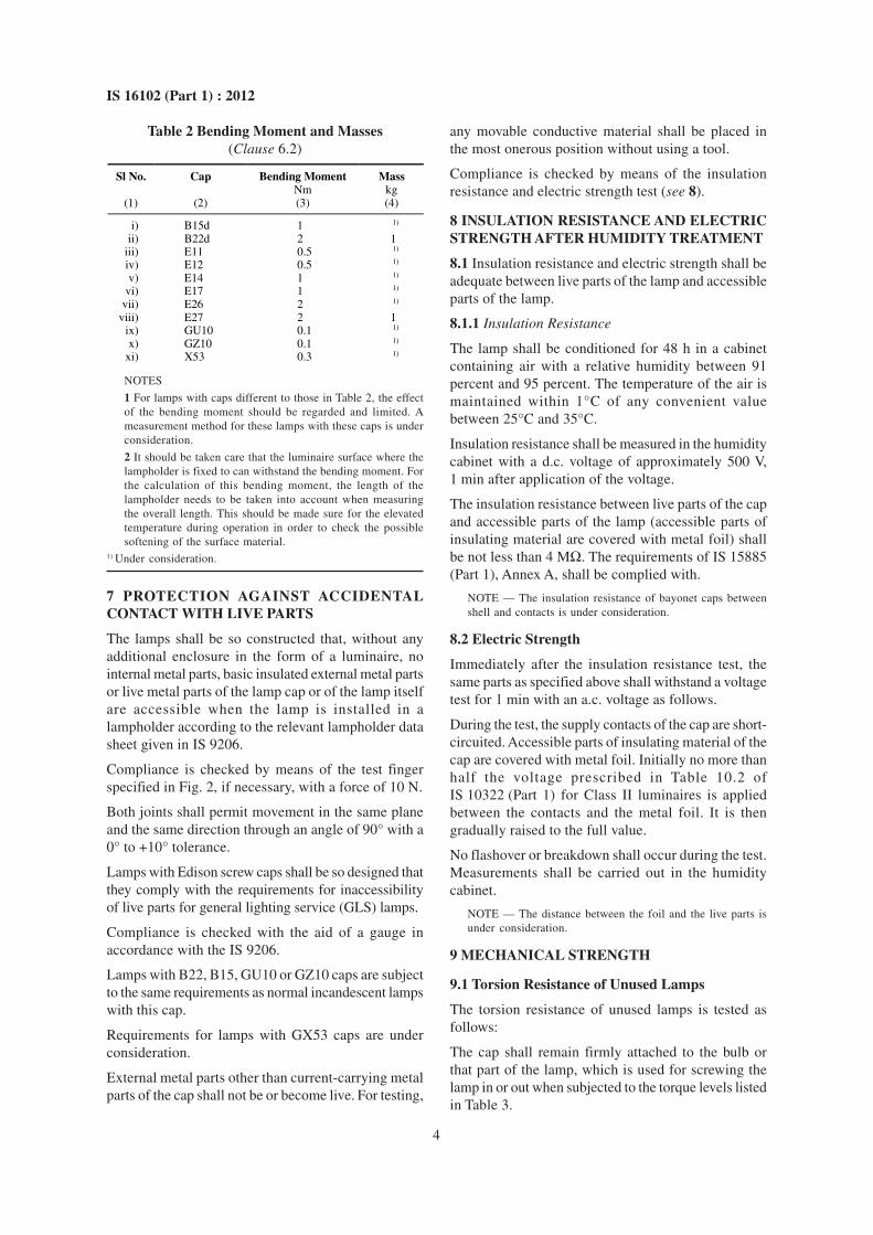
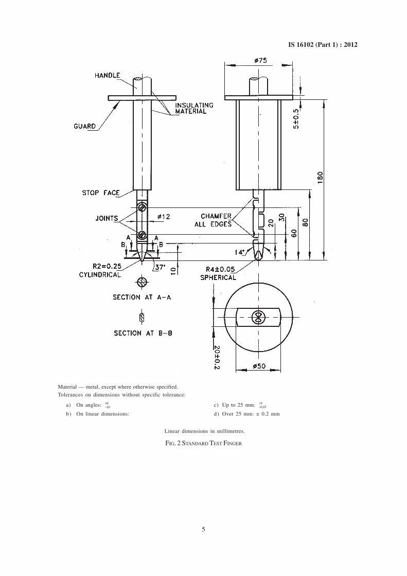
Compliance is checked by means of the test fingerspecified in Fig. 2, if necessary, with a force of 10 N.
Both joints shall permit movement in the same planeand the same direction through an angle of 90° with a0° to +10° tolerance.
Lamps with Edison screw caps shall be so designed thatthey comply with the requirements for inaccessibilityof live parts for general lighting service (GLS) lamps.
Compliance is checked with the aid of a gauge inaccordance with the IS 9206.
Lamps with B22, B15, GU10 or GZ10 caps are subjectto the same requirements as normal incandescent lampswith this cap.
Requirements for lamps with GX53 caps are underconsideration.
External metal parts other than current-carrying metalparts of the cap shall not be or become live. For testing,
any movable conductive material shall be placed inthe most onerous position without using a tool.
Compliance is checked by means of the insulationresistance and electric strength test (see 8).
8 INSULATION RESISTANCE AND ELECTRICSTRENGTH AFTER HUMIDITY TREATMENT
8.1 Insulation resistance and electric strength shall beadequate between live parts of the lamp and accessibleparts of the lamp.
8.1.1 Insulation Resistance
The lamp shall be conditioned for 48 h in a cabinetcontaining air with a relative humidity between 91percent and 95 percent. The temperature of the air ismaintained within 1°C of any convenient valuebetween 25°C and 35°C.
Insulation resistance shall be measured in the humiditycabinet with a d.c. voltage of approximately 500 V,1 min after application of the voltage.
The insulation resistance between live parts of the capand accessible parts of the lamp (accessible parts ofinsulating material are covered with metal foil) shallbe not less than 4 MΩ. The requirements of IS 15885(Part 1), Annex A, shall be complied with.
NOTE — The insulation resistance of bayonet caps betweenshell and contacts is under consideration.
8.2 Electric Strength
Immediately after the insulation resistance test, thesame parts as specified above shall withstand a voltagetest for 1 min with an a.c. voltage as follows.
During the test, the supply contacts of the cap are short-circuited. Accessible parts of insulating material of thecap are covered with metal foil. Initially no more thanhalf the voltage prescribed in Table 10.2 ofIS 10322 (Part 1) for Class II luminaires is appliedbetween the contacts and the metal foil. It is thengradually raised to the full value.
No flashover or breakdown shall occur during the test.Measurements shall be carried out in the humiditycabinet.
NOTE — The distance between the foil and the live parts isunder consideration.
9 MECHANICAL STRENGTH
9.1 Torsion Resistance of Unused Lamps
The torsion resistance of unused lamps is tested asfollows:
The cap shall remain firmly attached to the bulb orthat part of the lamp, which is used for screwing thelamp in or out when subjected to the torque levels listedin Table 3.
5
IS 16102 (Part 1) : 2012
Material — metal, except where otherwise specified.
Tolerances on dimensions without specific tolerance:
a) On angles: 0–10'+ c) Up to 25 mm: 0
–0,05+
b) On linear dimensions: d) Over 25 mm: ± 0.2 mm
Linear dimensions in millimetres.
FIG. 2 STANDARD TEST FINGER

6
IS 16102 (Part 1) : 2012
Table 3 Torque Test Values for Unused Lamps(Clause 9.1)
Sl No. Cap Torsion Moment Nm
(1) (2) (3)
i) B15d 1.15 ii) B 22 d 3
iii) E 11 0.8 iv) E 12 0.8 v) E 14 1.15
vi) E 17 1.5 vii) E 27 3
viii) GX 53 3 (under consideration)
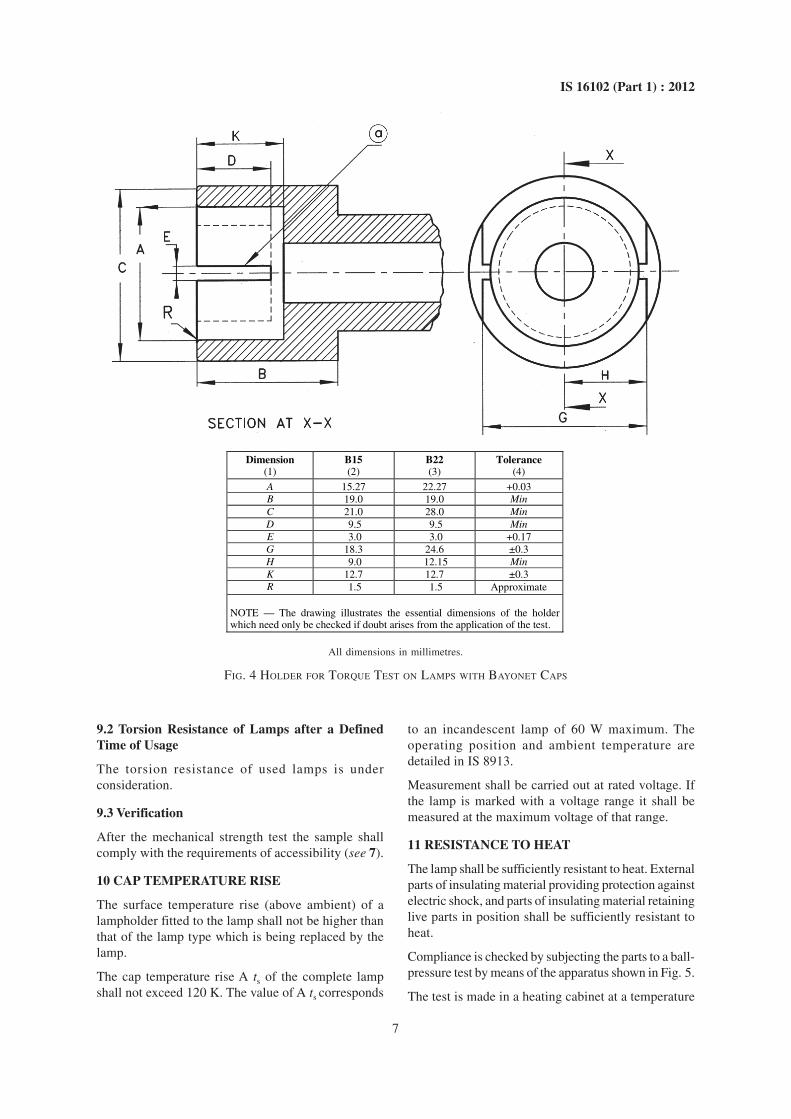
Tests are made according to the description of therelevant lamp standard per lamp type in IS 15518(Part 1) by means of the test holders shown in Fig. 3and Fig. 4.
The torque shall not be applied suddenly, but shall beincreased continuously from zero to the specified value.
In the case of un-cemented caps, relative movementbetween cap and bulb is permitted provided it doesnot exceed 10°.
Surface finish of screw thread Ra = 0.4 µm, Min (see Note).
NOTE — A smoother surface might result in mechanical overloading of the cap (see also C-1.2 of IS 15518).
Dimension E12 E14 E17 E26 and E26d E27 Tolerance (1) (2) (3) (4) (5) (6) (7)
C 15.27 20.0 20.0 32.0 32.0 Min
K 9.0 11.5 10.0 11.0 13.5 0.0–0.3
O 9.5 12.0 14.0 23.0 23.0 +0.1–0.1
S 4.0 7.0 8.0 12.0 12.0 Min
d 11.89 13.89 16.64 26.492 26.45 +0.1
0.0
d1 10.62 12.29 15.27 24.816 24.26 +0.1
0.0
P 2.540 2.822 2.822 3.629 3.629 — r 0.792 0.822 0.897 1.191 1.025 —
NOTE — The drawing illustrates the essential dimensions of the holder which need only be checked if doubt arises from the application of the test.
All dimensions in millimetres.
FIG. 3 HOLDER FOR TORQUE TEST ON LAMPS WITH SCREW CAPS
7
IS 16102 (Part 1) : 2012
Dimension B15 B22 Tolerance (1) (2) (3) (4)
A 15.27 22.27 +0.03 B 19.0 19.0 Min C 21.0 28.0 Min D 9.5 9.5 Min E 3.0 3.0 +0.17 G 18.3 24.6 ±0.3 H 9.0 12.15 Min K 12.7 12.7 ±0.3 R 1.5 1.5 Approximate
NOTE — The drawing illustrates the essential dimensions of the holder which need only be checked if doubt arises from the application of the test.
All dimensions in millimetres.
FIG. 4 HOLDER FOR TORQUE TEST ON LAMPS WITH BAYONET CAPS
9.2 Torsion Resistance of Lamps after a DefinedTime of Usage
The torsion resistance of used lamps is underconsideration.
9.3 Verification
After the mechanical strength test the sample shallcomply with the requirements of accessibility (see 7).
10 CAP TEMPERATURE RISE
The surface temperature rise (above ambient) of alampholder fitted to the lamp shall not be higher thanthat of the lamp type which is being replaced by thelamp.
The cap temperature rise A ts of the complete lampshall not exceed 120 K. The value of A ts corresponds
to an incandescent lamp of 60 W maximum. Theoperating position and ambient temperature aredetailed in IS 8913.
Measurement shall be carried out at rated voltage. Ifthe lamp is marked with a voltage range it shall bemeasured at the maximum voltage of that range.
11 RESISTANCE TO HEAT
The lamp shall be sufficiently resistant to heat. Externalparts of insulating material providing protection againstelectric shock, and parts of insulating material retaininglive parts in position shall be sufficiently resistant toheat.
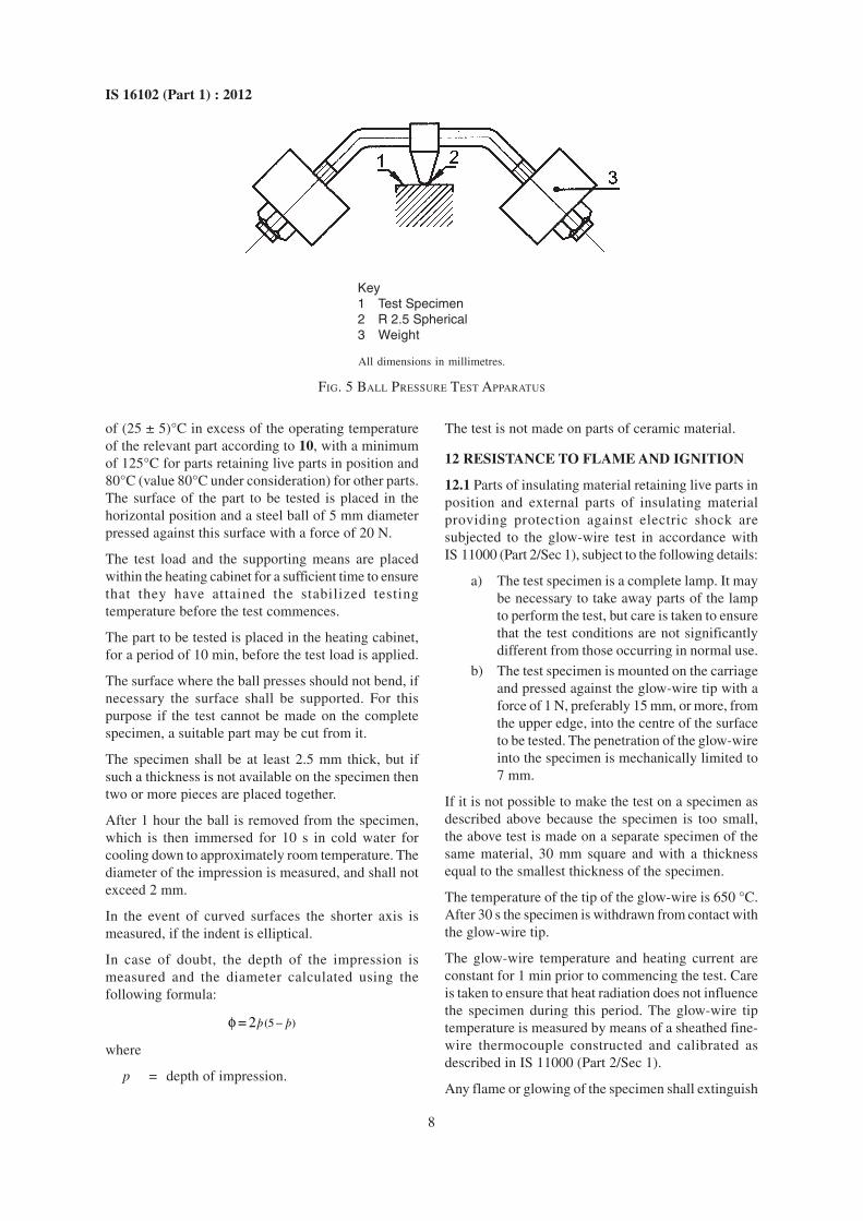
Compliance is checked by subjecting the parts to a ball-pressure test by means of the apparatus shown in Fig. 5.
The test is made in a heating cabinet at a temperature
8
IS 16102 (Part 1) : 2012
of (25 ± 5)°C in excess of the operating temperatureof the relevant part according to 10, with a minimumof 125°C for parts retaining live parts in position and80°C (value 80°C under consideration) for other parts.The surface of the part to be tested is placed in thehorizontal position and a steel ball of 5 mm diameterpressed against this surface with a force of 20 N.
The test load and the supporting means are placedwithin the heating cabinet for a sufficient time to ensurethat they have attained the stabilized testingtemperature before the test commences.
The part to be tested is placed in the heating cabinet,for a period of 10 min, before the test load is applied.
The surface where the ball presses should not bend, ifnecessary the surface shall be supported. For thispurpose if the test cannot be made on the completespecimen, a suitable part may be cut from it.
The specimen shall be at least 2.5 mm thick, but ifsuch a thickness is not available on the specimen thentwo or more pieces are placed together.
After 1 hour the ball is removed from the specimen,which is then immersed for 10 s in cold water forcooling down to approximately room temperature. Thediameter of the impression is measured, and shall notexceed 2 mm.
In the event of curved surfaces the shorter axis ismeasured, if the indent is elliptical.
In case of doubt, the depth of the impression ismeasured and the diameter calculated using thefollowing formula:
-f (5 )= 2þ þ
where
p = depth of impression.
The test is not made on parts of ceramic material.
12 RESISTANCE TO FLAME AND IGNITION
12.1 Parts of insulating material retaining live parts inposition and external parts of insulating materialproviding protection against electric shock aresubjected to the glow-wire test in accordance withIS 11000 (Part 2/Sec 1), subject to the following details:
a) The test specimen is a complete lamp. It maybe necessary to take away parts of the lampto perform the test, but care is taken to ensurethat the test conditions are not significantlydifferent from those occurring in normal use.
b) The test specimen is mounted on the carriageand pressed against the glow-wire tip with aforce of 1 N, preferably 15 mm, or more, fromthe upper edge, into the centre of the surfaceto be tested. The penetration of the glow-wireinto the specimen is mechanically limited to7 mm.
If it is not possible to make the test on a specimen asdescribed above because the specimen is too small,the above test is made on a separate specimen of thesame material, 30 mm square and with a thicknessequal to the smallest thickness of the specimen.
The temperature of the tip of the glow-wire is 650 °C.After 30 s the specimen is withdrawn from contact withthe glow-wire tip.
The glow-wire temperature and heating current areconstant for 1 min prior to commencing the test. Careis taken to ensure that heat radiation does not influencethe specimen during this period. The glow-wire tiptemperature is measured by means of a sheathed fine-wire thermocouple constructed and calibrated asdescribed in IS 11000 (Part 2/Sec 1).
Any flame or glowing of the specimen shall extinguish
All dimensions in millimetres.
FIG. 5 BALL PRESSURE TEST APPARATUS
Key1 Test Specimen2 R 2.5 Spherical3 Weight

9
IS 16102 (Part 1) : 2012
within 30 s of withdrawing the glow-wire, and anyflaming drop shall not ignite a piece of the tissue paper,spread out horizontally 200 ± 5 mm below thespecimen. The tissue paper is specified in IS 4261.
The test is not made on parts of ceramic material.
13 FAULT CONDITIONS
13.1 General
Lamps shall not impair safety when operated underfault conditions, which may occur during the intendeduse. Each of the following fault conditions is appliedin turn, as well as any other associated fault conditionsthat may arise from them as logical consequence.
13.2 Extreme Electrical Conditions (DimmableLamps)
If lamps are marked with a voltage range, rated voltageis taken as the maximum and minimum of the voltagerange marked unless the manufacturer declares anothervoltage as the most critical one. The lamp is switchedon at ambient temperature (definition given in IS 16001and conditions as given in H-1 of IS 15885 (Part 1)and adjusted to the most critical electrical conditionsas indicated by the manufacturer or the power isincreased until 150 percent of the rated power isreached. The test is continued until the lamp isthermally stabilized. A stable condition is reached, ifthe lamp cap temperature does not change by morethan 1 K as specified in IS 8913. The lamp shallwithstand the extreme electrical conditions for at least15 min, after stabilization is reached.
A lamp which fails safe and has withstood the extremeelectrical conditions for 15 min, has passed the test,provided, the compliance (see 4.1 and 13.6) is fulfilled.
If the lamp contains an automatic protective device orcircuit which limits the power, it is subjected to a15 min operation at this limit. If the device or circuiteffectively limits the power over this period, the lamphas passed the test, provided, the compliance (see 4.1and 13.4) is fulfilled.
13.3 Extreme Electrical Conditions (Non-dimmableLamps)
Lamps, which according to the marking, are notsuitable for dimming, shall be tested as far as possibleaccording to 13.2 under the most adverse electricalconditions as indicated by the manufacturer. If lampsare marked with a voltage range, rated voltage is takenas the maximum and minimum of the voltage rangemarked unless the manufacturer declares anothervoltage as the most critical one.
13.4 Short-Circuit Across Capacitors
Only one component at a time is subjected to a faultcondition.
13.5 Fault Conditions Across Electronic Components
Open or bridge points in the circuit where the diagramindicates that such a fault condition may impair safety.
Only one component at a time is subjected to a faultcondition.
13.6 Compliance
During the tests 13.2 to 13.5 the lamp shall not catchfire, or produce flammable gases or smoke and liveparts shall not become accessible.
To check if gases liberated from component parts areflammable or not, a test with a high-frequency sparkgenerator is made.
To check if accessible parts have become live, a test inaccordance with 7 is made.
After testing in 13.2 to 13.5, the lamp shall meet theinsulation resistance requirements of 8.1 except theapplied voltage shall be a d.c. voltage of approximately1 000 V.
14 CREEPAGE DISTANCES AND CLEARANCES
The requirements of IS 15885 (Part 1) shall apply.
15 SELECTION OF LAMPS FOR TESTS(SAMPLING)
15.1 Method of Selection
The inspection test quantities (ITQ) shall be selectedin a mutually agreed manner such as to ensure properrepresentation of the batch. The selection of lamps forindividual batches should be made as follows:
a) Up to and Including 20 Containers per Batch— Out of every container an equal numberof lamps (or as near to equal as possible) shallbe selected at random in order to obtain 25lamps required.
b) Over 20 Containers per Batch — Out of 20containers, every distributed over the wholebatch, one lamp shall be selected at randomfrom each container to obtain the 25 lampsrequired.
NOTE — Method of selection of lamps for type testingare under consideration.
15.2 Inspection Test Quantity (ITQ)
Inspection test quantity shall consist of 25 lamps.

10
IS 16102 (Part 1) : 2012
15.3 Accidentally Broken and/or in CorrectedOperated Lamps
15.3.1 Lamps, which are accidentally broken, shall,when necessary, be replaced to ensure that the requirednumber of lamps for performance requirementscompleted the test. Any such broken or incorrectlyoperated lamps shall be neglected in the evaluation oflife test results specified in IS 16002 (Part 2).
NOTE — In order to avoid unnecessary delay, it isrecommended that spare lamps be available for carrying outother tests of this standard including tests specified in Part 2of this standard.
16 CONDITIONS OF COMPLIANCE
16.1 General Conditions
A batch shall be considered as confirming to thisstandard, if the requirements contained in this standardare fulfilled. If the batch fails to satisfy the requirementsof any of these requirements, it shall be deemed not tocomply with this standard.
16.2 Test for Inspection Test Quantity
16.2.1 Following shall constitute inspection tests:
a) Marking;
b) Interchangeability;c) Protection against electric shock;
d) Insulation resistance and electric strength afterhumidity treatment; and
e) Mechanical strength.
A batch shall be considered to comply, if the numberof lamps failing does not exceed qualifying limits givenbelow:
a) For any single requirement: 2, Max; and
b) For all requirements taken together: 4, Max.
17 TESTS
17.1 Classification of Tests
17.1.1 Type Tests
The following shall constitute the type tests to be
carried out on selected sample of self-ballasted lamps,sample being drawn preferably from regular productionlot. The tests are carried out in order of the clauses:
a) Marking (see 5);b) Interchangeability (see 6);
c) Protection against electric shock (see 7);
d) Insulation resistance and electric strength afterhumidity treatment (see 8);
e) Mechanical strength (see 9);
f) Cap temperature rise (see 10);
g) Resistance to heat (see 11);h) Resistance to flame and ignition (see 12);
j) Fault conditions (see 13); and
k) Creepage distances and clearances (see 14).
17.1.2 The number of sample shall be as given for ITQin respect of tests for 5 to 9 and their criteria foracceptance is given in 16.2.
17.1.3 The number of samples for temperature risewhen tested in accordance with 10 shall be five fromwhich not more than one shall fail.
17.1.4 The number of samples for resistance toheat (see 11), resistance to flame and ignition (see 12)and fault condition (see 14) shall be one and no failuresare allowed in any of these tests.
17.2 Acceptance Test
The following shall constitute as acceptance tests:
a) Marking (see 5);
b) Interchangeability (see 6);
c) Protection against electric shock (see 7);d) Insulation resistance and electric strength after
humidity treatment (see 8);
e) Mechanical strength (see 9); and
f) Cap temperature rise (see 10).
17.2.1 Sampling shall be the same as given againstITQ in respect of test of 5 to 9 and five in respectof test of 10. Criteria for acceptance shall be asgiven in 16.2 for cap temperature rise the numberof failure shall not exceed one.
11
IS 16102 (Part 1) : 2012
ANNEX A(Clause 1)
OVERVIEW OF SYSTEMS COMPOSED OF LED MODULES AND CONTROLGEAR
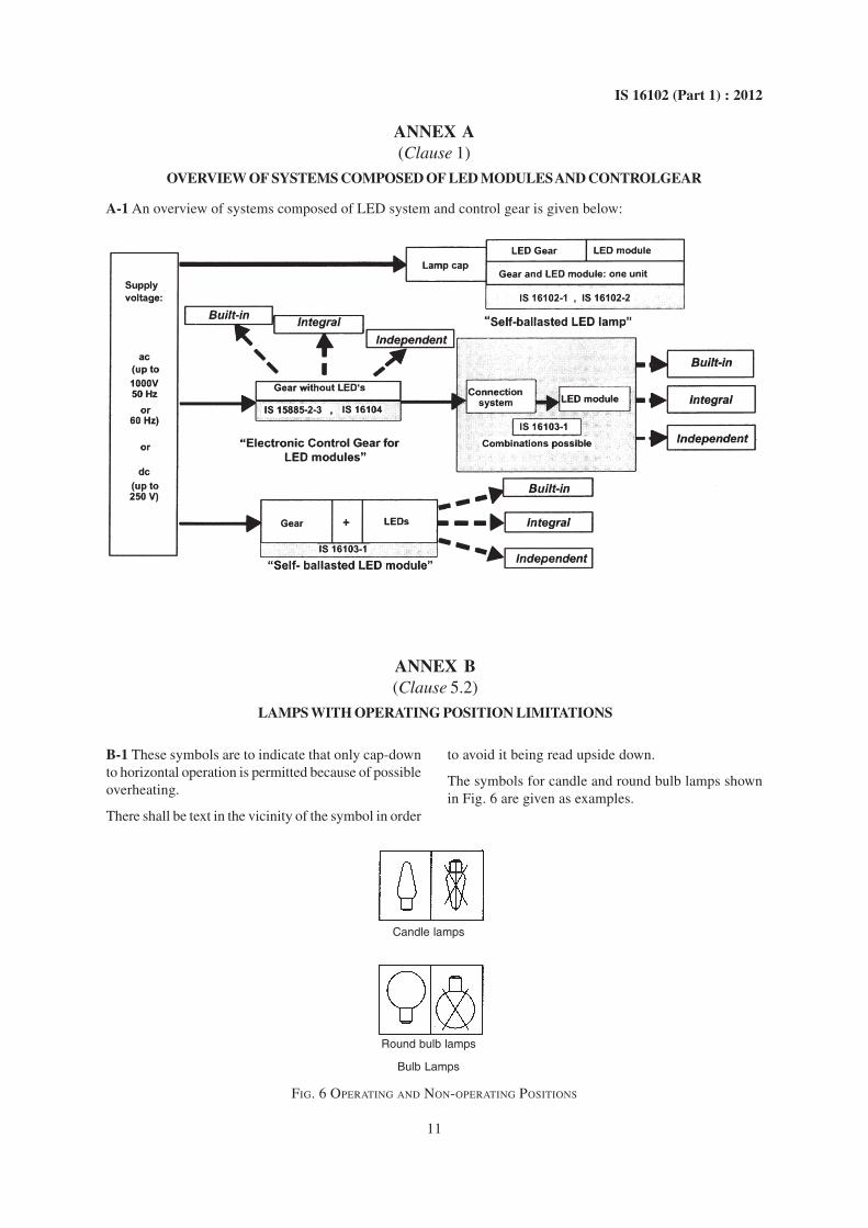
A-1 An overview of systems composed of LED system and control gear is given below:
B-1 These symbols are to indicate that only cap-downto horizontal operation is permitted because of possibleoverheating.
There shall be text in the vicinity of the symbol in order
ANNEX B(Clause 5.2)
LAMPS WITH OPERATING POSITION LIMITATIONS
FIG. 6 OPERATING AND NON-OPERATING POSITIONS
to avoid it being read upside down.
The symbols for candle and round bulb lamps shownin Fig. 6 are given as examples.
Candle lamps
Round bulb lamps
Bulb Lamps
Published by BIS, New Delhi
Bureau of Indian Standards
BIS is a statutory institution established under the Bureau of Indian Standards Act, 1986 to promoteharmonious development of the activities of standardization, marking and quality certification of goodsand attending to connected matters in the country.
Copyright
BIS has the copyright of all its publications. No part of these publications may be reproduced in any formwithout the prior permission in writing of BIS. This does not preclude the free use, in the course ofimplementing the standard, of necessary details, such as symbols and sizes, type or grade designations.Enquiries relating to copyright be addressed to the Director (Publications), BIS.
Review of Indian Standards
Amendments are issued to standards as the need arises on the basis of comments. Standards are also reviewedperiodically; a standard along with amendments is reaffirmed when such review indicates that no changes areneeded; if the review indicates that changes are needed, it is taken up for revision. Users of Indian Standardsshould ascertain that they are in possession of the latest amendments or edition by referring to the latest issue of‘BIS Catalogue’ and ‘Standards : Monthly Additions’.
This Indian Standard has been developed from Doc No.: ETD 23 (6298).
Amendments Issued Since Publication
Amend No. Date of Issue Text Affected
BUREAU OF INDIAN STANDARDS
Headquarters:
Manak Bhavan, 9 Bahadur Shah Zafar Marg, New Delhi 110002Telephones : 2323 0131, 2323 3375, 2323 9402 Website: www.bis.org.in
Regional Offices: Telephones
Central : Manak Bhavan, 9 Bahadur Shah Zafar Marg 2323 7617NEW DELHI 110002 2323 3841
Eastern : 1/14 C.I.T. Scheme VII M, V. I. P. Road, Kankurgachi 2337 8499, 2337 8561KOLKATA 700054 2337 8626, 2337 9120
Northern : SCO 335-336, Sector 34-A, CHANDIGARH 160022 60 384360 9285
Southern : C.I.T. Campus, IV Cross Road, CHENNAI 600113 2254 1216, 2254 14422254 2519, 2254 2315
Western : Manakalaya, E9 MIDC, Marol, Andheri (East) 2832 9295, 2832 7858MUMBAI 400093 2832 7891, 2832 7892
Branches: AHMEDABAD. BANGALORE. BHOPAL. BHUBANESHWAR. COIMBATORE. DEHRADUN.FARIDABAD. GHAZIABAD. GUWAHATI. HYDERABAD. JAIPUR. KANPUR. LUCKNOW.NAGPUR. PARWANOO. PATNA. PUNE. RAJKOT. THIRUVANANTHAPURAM.VISAKHAPATNAM.