isdb-t seminar in brazil - dibeg | isdb-t official web site · key technology for improvement of...
TRANSCRIPT
ISDB-T seminar in Brazil
Seminar #5
Transmission system (part 2)
30th March, 2005Digital Broadcasting Expert Group (DiBEG)
Yasuo TAKAHSHI
(Toshiba)
1. Digital terrestrial sound broadcasting(continued)1.1 Outline and feature of DTSB1.2 Infrastructure of broadcaster1.3 Current state of receiver1.4 Channel allocation and example of program time table2. Transmission performance of ISDB-T2.1 Fundamental performance of ISDB-T2.2 Test result in Brazil2.3 Protection ratio 3. Key technology for improvement of ISDB-T transmission characteristics (transmitter and micro-wave relay) 4. Key technology for improvement of ISDB-T transmission characteristics (transmitter and micro-wave relay)
Contents
1.Digital Terrestrial Sound Broadcasting
In this section, outline of digital terrestrial sound broadcasting described below are introduced. Most of document is dedicated by DRP(Digital Radio Promotion Association).
-outline and feature of digital terrestrial sound broadcasting
-infrastructure of broadcaster
-current state of receiver
-channel allocation and program time table
Digital Terrestrial Sound Broadcasting (DTSB)
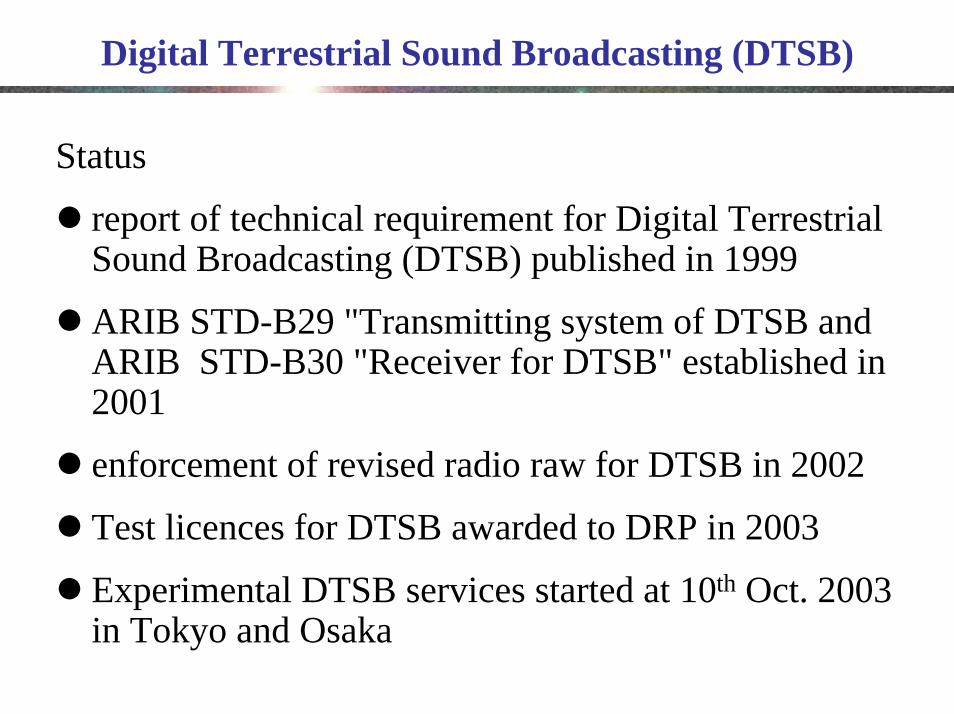
Status
report of technical requirement for Digital Terrestrial Sound Broadcasting (DTSB) published in 1999
ARIB STD-B29 "Transmitting system of DTSB and ARIB STD-B30 "Receiver for DTSB" established in 2001
enforcement of revised radio raw for DTSB in 2002
Test licences for DTSB awarded to DRP in 2003
Experimental DTSB services started at 10th Oct. 2003 in Tokyo and Osaka
Digital Terrestrial Sound Broadcasting System
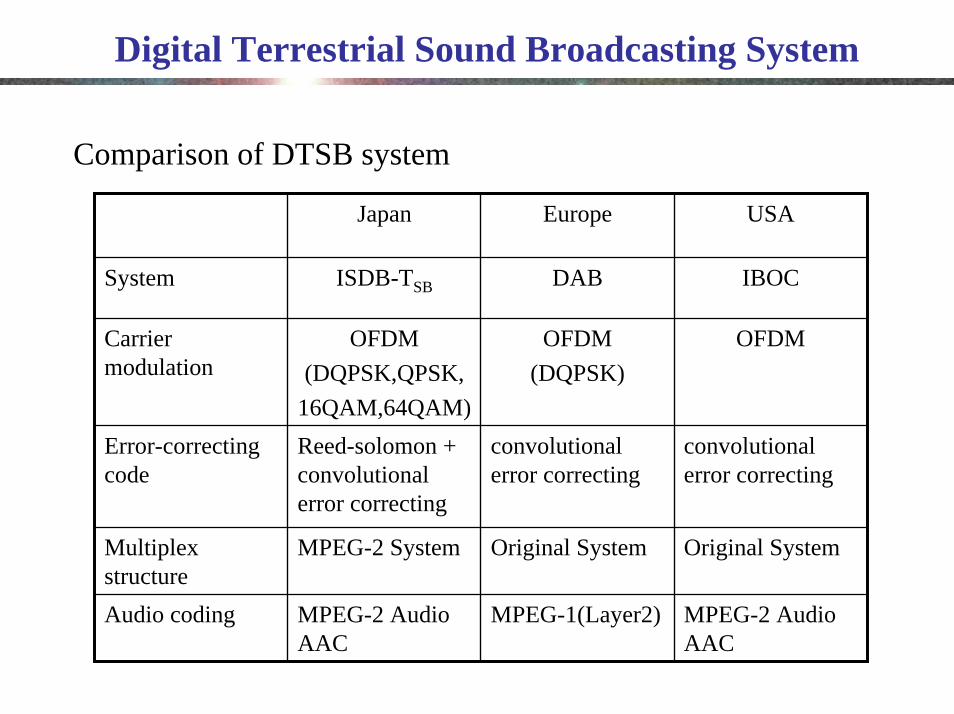
MPEG-2 Audio AAC
MPEG-1(Layer2)MPEG-2 Audio AAC
Audio coding
Original SystemOriginal SystemMPEG-2 SystemMultiplex structure
convolutionalerror correcting
convolutionalerror correcting
Reed-solomon + convolutionalerror correcting
Error-correcting code
OFDMOFDM(DQPSK)
OFDM(DQPSK,QPSK,
16QAM,64QAM)
Carrier modulation
IBOCDABISDB-TSBSystem
USAEuropeJapan
Comparison of DTSB system
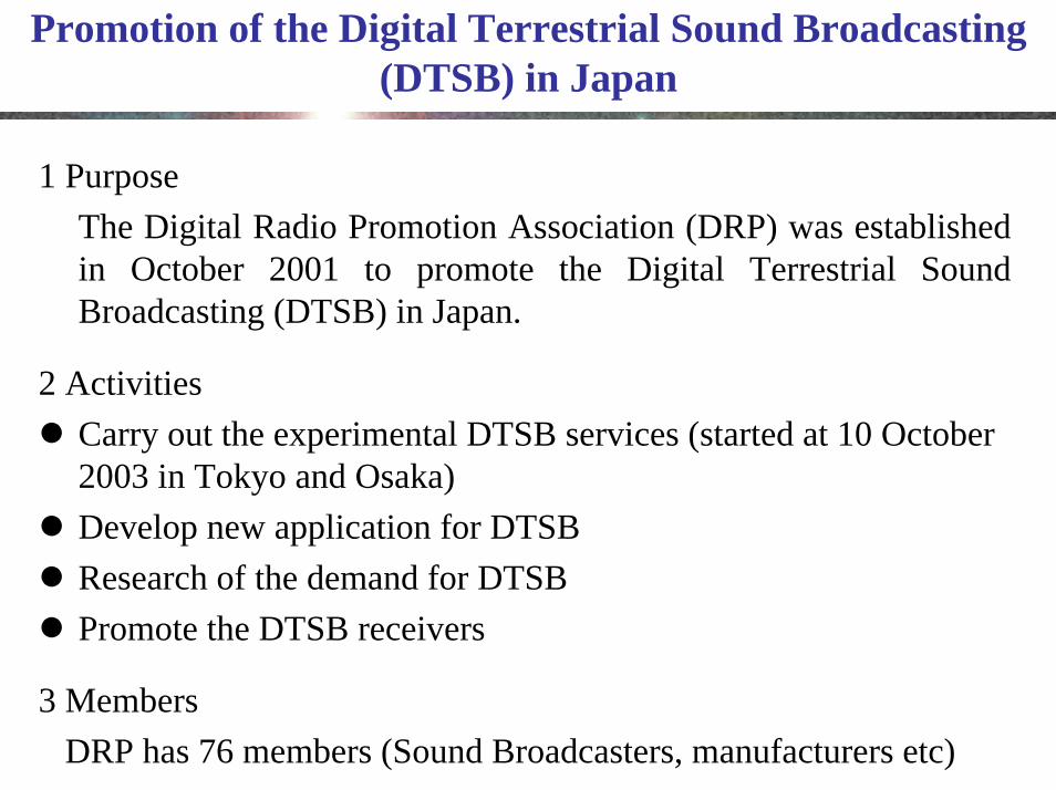
Promotion of the Digital Terrestrial Sound Broadcasting (DTSB) in Japan
1 PurposeThe Digital Radio Promotion Association (DRP) was established in October 2001 to promote the Digital Terrestrial Sound Broadcasting (DTSB) in Japan.
2 ActivitiesCarry out the experimental DTSB services (started at 10 October 2003 in Tokyo and Osaka)Develop new application for DTSBResearch of the demand for DTSBPromote the DTSB receivers
3 MembersDRP has 76 members (Sound Broadcasters, manufacturers etc)

Feature of digital terrestrial sound broadcasting
Digital Terrestrial Sound Broadcasting(DTSB) is the new broadcasting service, which provide high quality audio(CD quality), still picture and simple motion picture. Through these media, many convenient service such as traffic information, liveinformation service are available.
In addition above, not only indoor but mobile and handheld reception is possible.
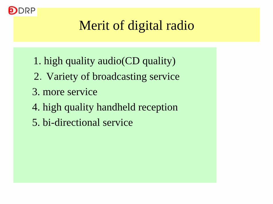
Merit of digital radio
1. high quality audio(CD quality) 2.Variety of broadcasting service
3. more service4. high quality handheld reception5. bi-directional service
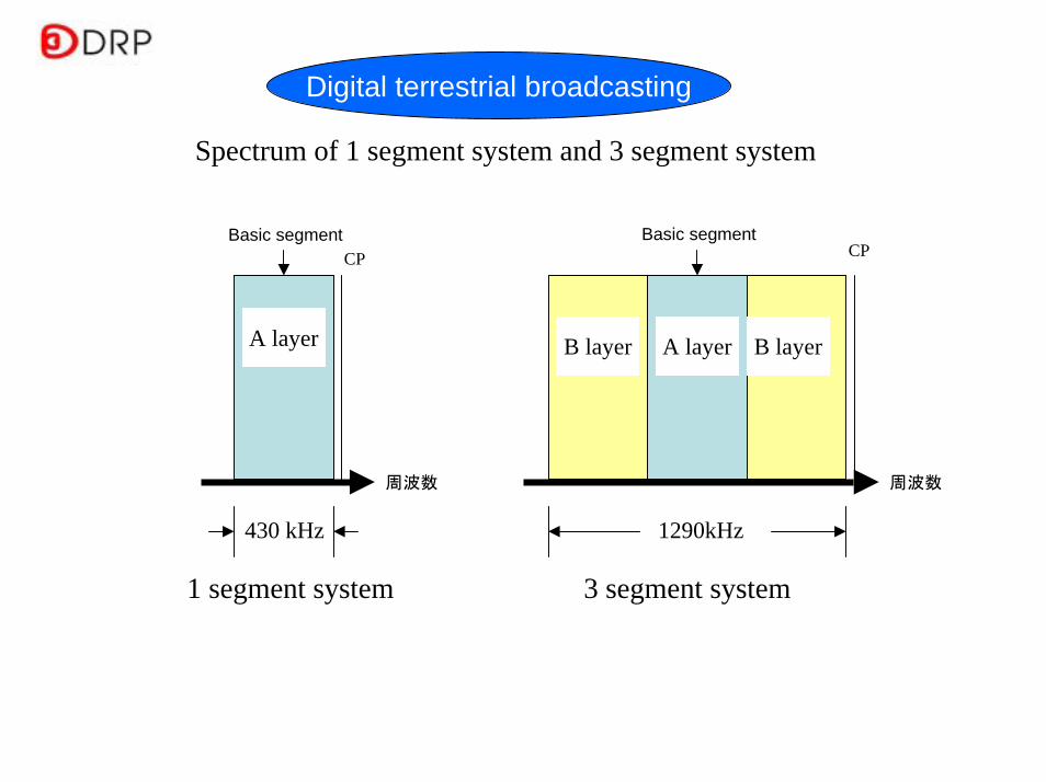
Spectrum of 1 segment system and 3 segment system
1 segment system
B layer
CP
周波数 周波数
430 kHz 1290kHz
Digital terrestrial broadcasting
Basic segment
A layer
Basic segmentCP
A layer B layer
3 segment system

Trial Services of DRP
VHF 6ch
18 segments(Normally 13seg.)
VHF 8chVHF 7ch
2MHz(Overlapping)
2 3 4 5 6 7 8
91ch 92ch 93ch 94ch 95ch 95ch
(Not use)
VHF television band assignments
6MHz 4MH
z
Segment structure
3seg. broadcasting
Broadcast programs
Above example is Tokyo station , Osaka's all programs are 1seg. broadcasting.
192MHz
188MHz

Outline of operation -1
QPSK 1/2, 2/316QAM 1/2
2( B layer)(extended segment)
QPSK 1/2, 2/316QAM 1/2
mobilehandheld
1( A layer)(basic segment)
3 segment
QPSK 1/2, 2/316QAM 1/2
mobilehandheld
1( A layer)(basic segment)
1 segment
Transmission parameter
Reception style
No. assigned segmentsystem
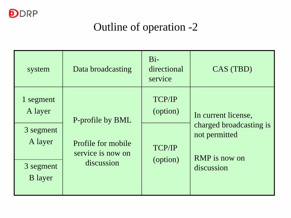
Outline of operation -2
3 segmentB layer
TCP/IP(option)
3 segmentA layer
In current license, charged broadcasting is not permitted
RMP is now on discussion
TCP/IP(option)
P-profile by BML
Profile for mobile service is now on
discussion
1 segmentA layer
CAS (TBD)Bi-directional service
Data broadcastingsystem
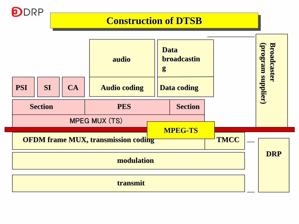
Broadcaster
Broadcaster
(program supplier)
(program supplier)
DRPDRP
PSIPSI SISI CACA
Section Section
TMCCTMCC
modulationmodulation
transmittransmit
audioaudio
Audio codingAudio coding
Data Data broadcastinbroadcastingg
Data codingData coding
PESPES
OFDM frame MUX, transmission codingOFDM frame MUX, transmission coding
MPEG MUX (TS)MPEG MUX (TS)
Section Section
MPEGMPEG--TSTS
Construction of DTSBConstruction of DTSBConstruction of DTSB

TV
Radio
Radio
Digital radio/digital TV compatible receiver
DTV receiver(VHF+UHF)
DTTB (UHF)13 segment (partial reception operation
DTSB (VHF)3 segment system
DTSB (VHF)1 segment system
3 segment receiver(VHF+UHF)
1 segment receiver(VHF+UHF)

(Tokyo) ShibaPark building.Each
broadcaster
Tokyo tower
antenna
Trial studio/transmitting station
Master roomTransmitter
room
CH91
CH92
CH93
CH98
・・・
Tokyo tower
(Osaka) TwinTower MID
Mt. Ikoma Mt. Ikoma
Tokyo (fiber)
Osaka (STL)
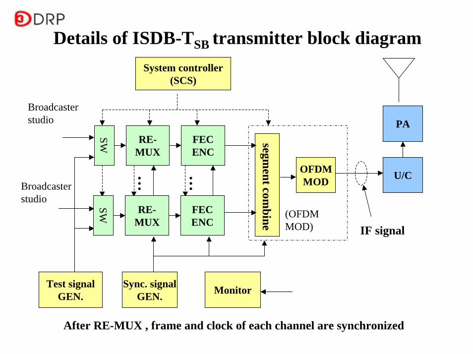
Details of ISDB-TSB transmitter block diagram
RE-MUX
…
FECENC
SW
Test signalGEN.
segment com
bine
OFDMMOD
Sync. signalGEN.
…
System controller(SCS)
(OFDM MOD)
Broadcaster studio
U/C
PA
Monitor
IF signal
After RE-MUX , frame and clock of each channel are synchronized
RE-MUX
FECENC
SW
Broadcaster studio
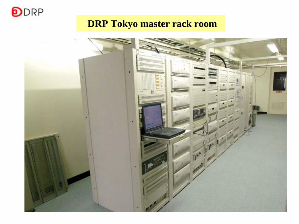
DRP Tokyo master rack room

DRP Tokyo digital radio transmitter room
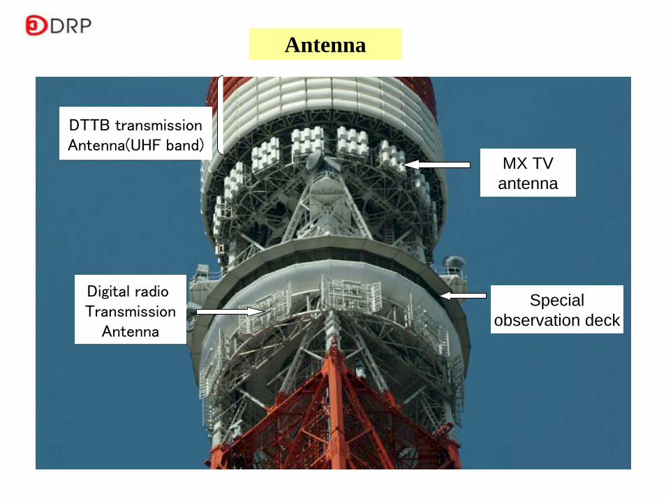
Antenna
Digital radio Transmission
Antenna
MX TVantenna
DTTB transmissionAntenna(UHF band)
Specialobservation deck
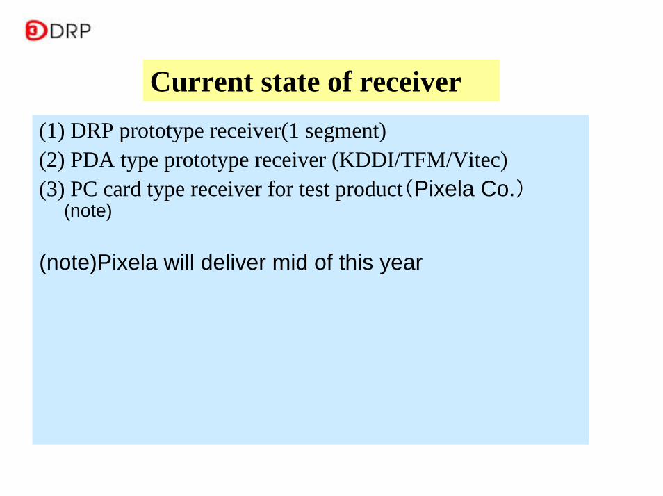
(1) DRP prototype receiver(1 segment)(2) PDA type prototype receiver (KDDI/TFM/Vitec)(3) PC card type receiver for test product(Pixela Co.)
(note)
(note)Pixela will deliver mid of this year
Current state of receiver

DRP prototype receiver(1 segment)

PDA type prototype receiver (KDDI/TFM/Vitec)

Pixela PC card type receiver
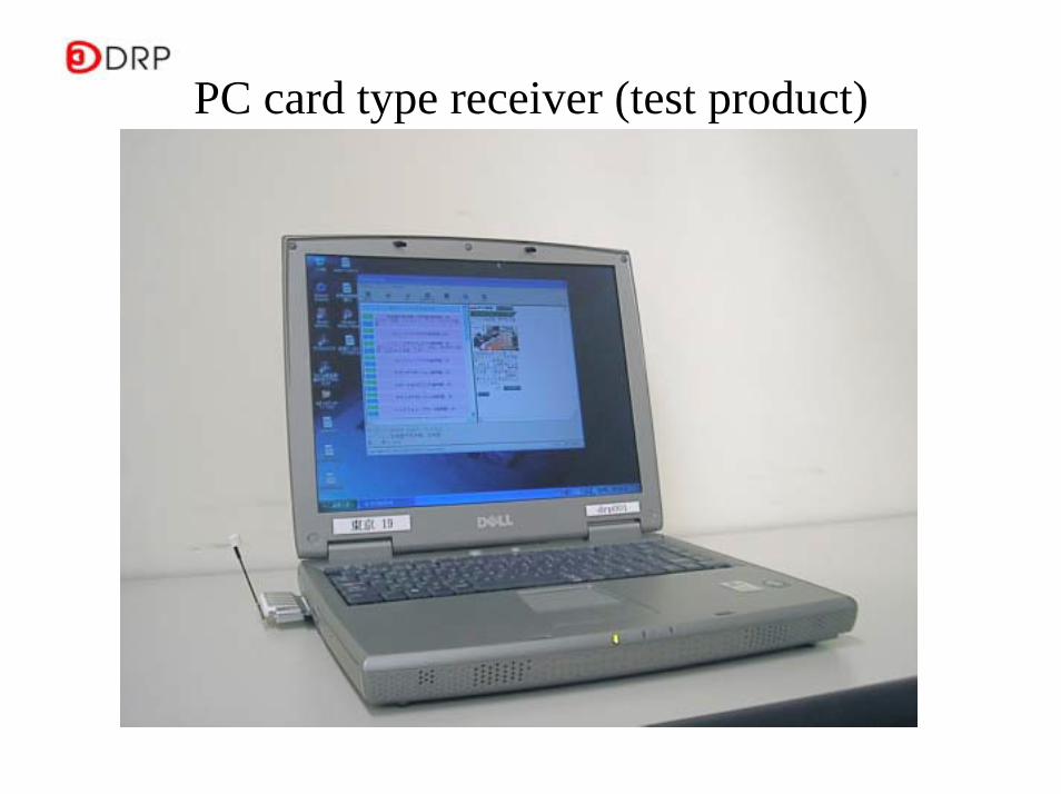
PC card type receiver (test product)

<Digital radio trial broadcasting>Channel construction
TOKYO FM
NIPPON broadcasting
JFNC (B member)
Ito-chuSONY
J-WAVEMega-portRadio NIPPON
NACK5QRTV asahi(B member)
FM YokohamaTBS radio & comunications゙BAYFMRadio NIKKEII
NHKVICS
98Digital Radio 98 The
Voice
95D95
94DAZ94
93DigiQ+
N93
92DR@
TOKYO92
91NHK
VICS
Tokyo Apr. 1st 2004
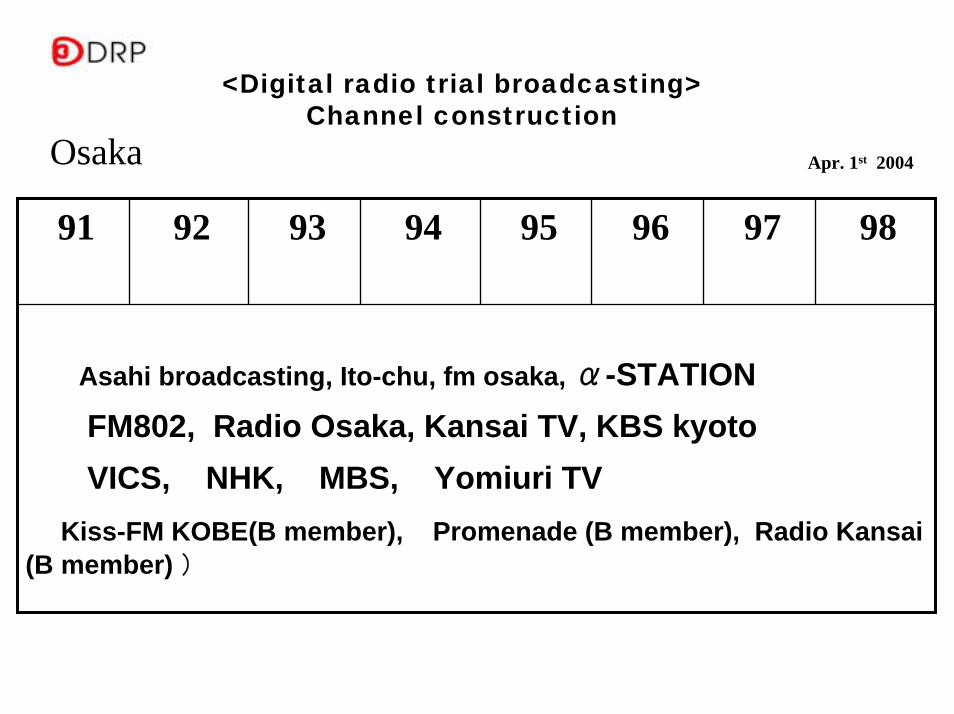
Asahi broadcasting, Ito-chu, fm osaka, α-STATIONFM802, Radio Osaka, Kansai TV, KBS kyotoVICS, NHK, MBS, Yomiuri TV
Kiss-FM KOBE(B member), Promenade (B member), Radio Kansai (B member) )
9897969594939291
<Digital radio trial broadcasting>Channel construction
Osaka Apr. 1st 2004
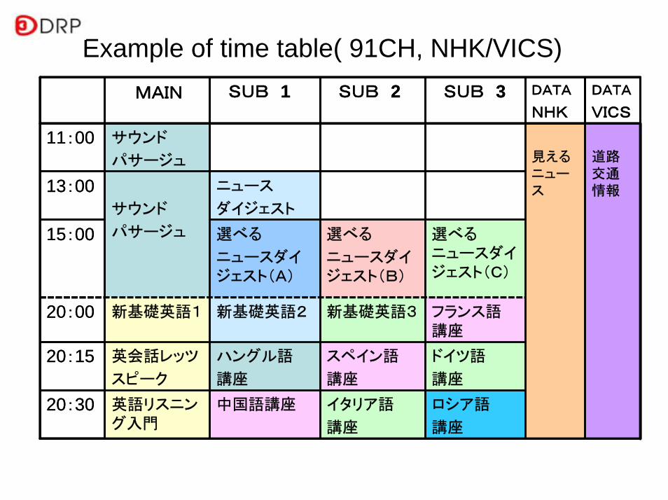
20:30
20:15
ロシア語
講座
イタリア語
講座
中国語講座英語リスニング入門
ドイツ語
講座
スペイン語
講座
ハングル語
講座
英会話レッツ
スピーク
選べるニュースダイジェスト(C)
選べる
ニュースダイジェスト(B)
選べる
ニュースダイジェスト(A)
15:00
フランス語講座
新基礎英語3新基礎英語2新基礎英語120:00
ニュース
ダイジェストサウンド
パサージュ
13:00
道路交通情報
見えるニュース
サウンド
パサージュ
11:00
DATA
VICS
DATA
NHK
SUB 3SUB 2SUB 1MAIN
20:30
20:15
ロシア語
講座
イタリア語
講座
中国語講座英語リスニング入門
ドイツ語
講座
スペイン語
講座
ハングル語
講座
英会話レッツ
スピーク
選べるニュースダイジェスト(C)
選べる
ニュースダイジェスト(B)
選べる
ニュースダイジェスト(A)
15:00
フランス語講座
新基礎英語3新基礎英語2新基礎英語120:00
ニュース
ダイジェストサウンド
パサージュ
13:00
道路交通情報
見えるニュース
サウンド
パサージュ
11:00
DATA
VICS
DATA
NHK
SUB 3SUB 2SUB 1MAIN
Example of time table( 91CH, NHK/VICS)

Music Stream くるくるThis is The
Voice 98
またたび アワー
No.1
14:00
くるくるThis is The
Voice 98
ヘルスセンター 98-213:00
くるくるThis is The
Voice 98
くるくるThis is The
Voice 98
Music StreamIt‘s 笑 Time
No.1
10:00
12:00 ヘルスセンター 98-1
くるくるThis is The
Voice 98
Music StreamIt‘s 笑 Time
No.2
11:00
データ放送音声2 or
音声3
音声2 or
簡易動画
音声1+静止画
ロゴ
Time table of Digital Radio 98 The Voice

Example of DTSB service
2. 2. Transmission performance of ISDBTransmission performance of ISDB--TT
2.1 Fundamental performance of ISDB-T
2.2 Test result in Brazil
2.3 Protection ratio
1.1 Fundamental performance of ISDB-T
ISDB-T system was standardized at 1998. At same time , proto type ISDB-T MODEM had been developed and was used to test the ISDB-T transmission performance. The experimental test results shown in this section were test result of ISDB-T initial stage.
From 1998, many of new technologies has been proposed and introduced. Several of these technologies are introduced in next section.
(note) At present, many new technologies has been developed and commercialized, therefore, present ISDB-T system has more high performance. The test result introduced in this section are just reference, not present ability.
(1)Results of Transmission Tests
The experimental test result, introduced here, was tested from 1998, in Tokyo Pilot Test.
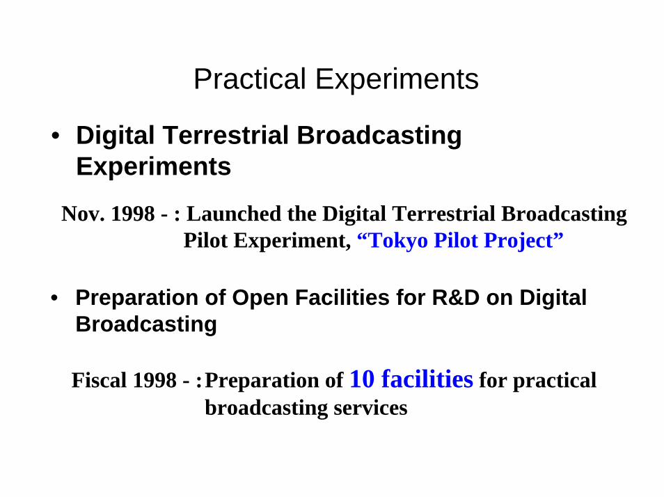
Practical Experiments
• Digital Terrestrial Broadcasting Experiments
• Preparation of Open Facilities for R&D on Digital Broadcasting
Nov. 1998 - : Launched the Digital Terrestrial Broadcasting Pilot Experiment, “Tokyo Pilot Project”
Fiscal 1998 - :Preparation of 10 facilities for practical broadcasting services
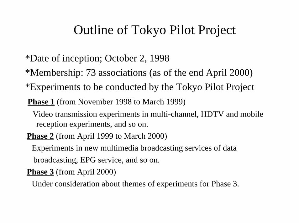
Outline of Tokyo Pilot Project
*Date of inception; October 2, 1998 *Membership: 73 associations (as of the end April 2000)*Experiments to be conducted by the Tokyo Pilot ProjectPhase 1 (from November 1998 to March 1999)
Video transmission experiments in multi-channel, HDTV and mobile reception experiments, and so on.
Phase 2 (from April 1999 to March 2000)Experiments in new multimedia broadcasting services of data broadcasting, EPG service, and so on.
Phase 3 (from April 2000)Under consideration about themes of experiments for Phase 3.
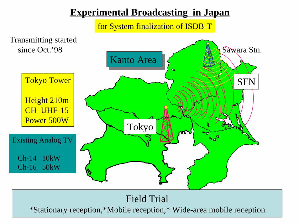
Experimental Broadcasting in Japanfor System finalization of ISDB-T
Kanto Area Kanto Area
Tokyo
Tokyo Tower
Height 210mCH UHF-15Power 500W
Sawara Stn.
SFN
Existing Analog TV
Ch-14 10kWCh-16 50kW
Transmitting startedsince Oct.’98
Field Trial*Stationary reception,*Mobile reception,* Wide-area mobile reception
60
65
70
75
80
85
90
95
100
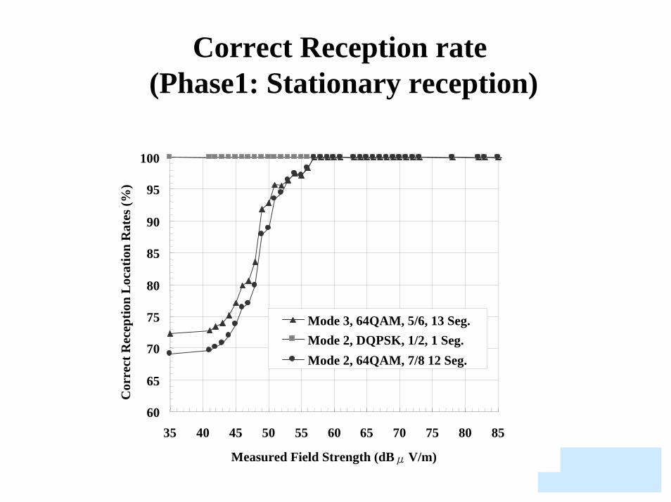
35 40 45 50 55 60 65 70 75 80 85
Measured Field Strength (dBμV/m)
Cor
rect
Rec
eptio
n L
ocat
ion
Rat
es (%
)
Mode 3, 64QAM, 5/6, 13 Seg.Mode 2, DQPSK, 1/2, 1 Seg.Mode 2, 64QAM, 7/8 12 Seg.
Correct Reception rate (Phase1: Stationary reception)

Comparison of Time Interleave(Phase1: Mobile reception)
70
75
80
85
90
95
100
35 40 45 50 55 60 65Measured Field Strength (dBμV/m)
Cor
rect
Rec
eptio
n T
ime
Rat
es (%
)
With Time Interleaving Without Time Interleaving
Mode 2, DQPSK, 1/2 , 13 seg.
99%
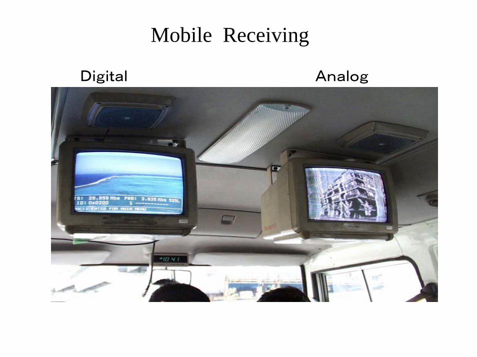
Mobile Receiving
Digital Analog

Correct reception time-rates (Phase1: Wide-area mobile reception)
6065707580859095
100
25 30 35 40 45 50 55 60Measured Field Strength [dBµV/m]
Cor
rect
Rec
eptio
n Ti
me
Rat
e[%
]
DQPSK16QAM
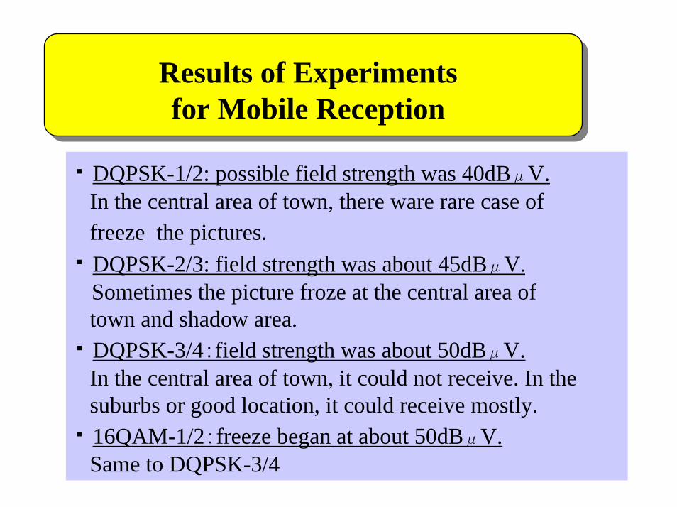
Results of Experiments for Mobile Reception
・ DQPSK-1/2: possible field strength was 40dBμV.In the central area of town, there ware rare case of freeze the pictures.
・ DQPSK-2/3: field strength was about 45dBμV.Sometimes the picture froze at the central area of town and shadow area.
・ DQPSK-3/4:field strength was about 50dBμV.In the central area of town, it could not receive. In the suburbs or good location, it could receive mostly.
・ 16QAM-1/2:freeze began at about 50dBμV.Same to DQPSK-3/4

2.2 Result of comparison test conduced by ABERT/SET of Brazil
Original published in Portuguese.
Translated in English
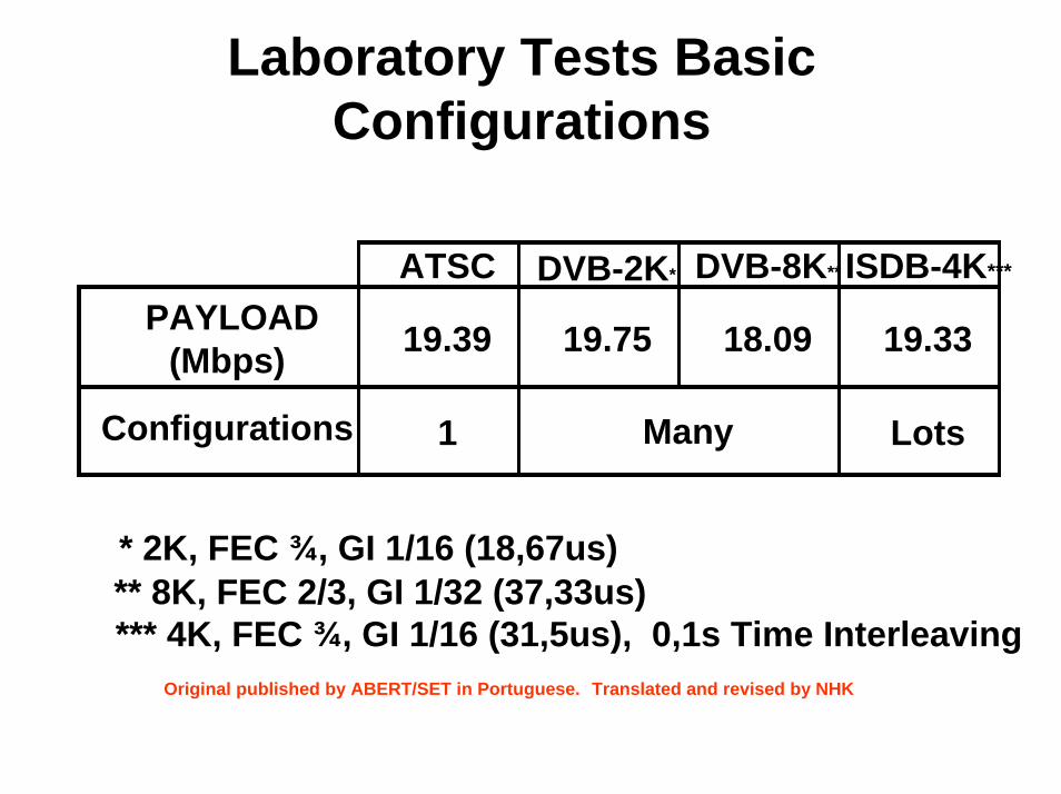
Laboratory Tests Basic Configurations
ATSC DVB-2K* DVB-8K** ISDB-4K***
PAYLOAD(Mbps) 19.39 19.75 18.09 19.33
Configurations 1 LotsMany
* 2K, FEC ¾, GI 1/16 (18,67us)** 8K, FEC 2/3, GI 1/32 (37,33us)*** 4K, FEC ¾, GI 1/16 (31,5us), 0,1s Time Interleaving
Original published by ABERT/SET in Portuguese. Translated and revised by NHK
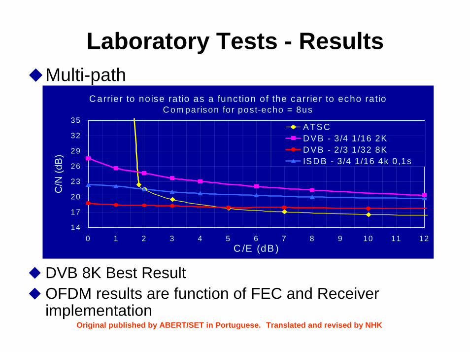
Laboratory Tests - ResultsMulti-path
DVB 8K Best ResultOFDM results are function of FEC and Receiver implementation
C arrier to noise ratio as a function of the carrier to echo ratioCom parison for post-echo = 8us
14
17
20
23
26
29
32
35
0 1 2 3 4 5 6 7 8 9 10 11 12C /E (dB )
C/N
(dB
)
A TS CDV B - 3/4 1/16 2KDV B - 2/3 1/32 8KIS DB - 3/4 1/16 4k 0,1s
Original published by ABERT/SET in Portuguese. Translated and revised by NHK

Laboratory Tests - ResultsImpulse Noise
ISDB – Best Results (Time Interleaving)DVB 8K Better than DVB 2K (5dB)
Interference to carrier ratio as a function of the noise pulse width
-10
0
10
20
30
0 100 200 300 400Pulse w idth (us)
"I"/C
(dB
)
ATSCD VB - 3/4 1/16 2KD VB - 2/3 1/32 8KISD B - 3/4 1/16 4K 0,1s
Original published by ABERT/SET in Portuguese. Translated and revised by NHK

Laboratory Tests - ResultsMobile Reception Simulation
ATSC did not work at 1.8 Km/hNumber of carriers is a key factorISDB 4K has similar performance to the DVB 2KDVB 8K only portable Rx.
Mobile Reception
0
100200300
400
500600
700800
4 6 8 10 12 14 16 18 20 22 24
Bit rate (Mbps)
Spee
d (K
m/h
)
DVB 2KDVB 8KISDB 2KISDB 4KISDB 8K
Mobile Reception
0
100200300
400
500600
700800
4 6 8 10 12 14 16 18 20 22 24
Bit rate (Mbps)
Spee
d (K
m/h
)
DVB 2KDVB 8KISDB 2KISDB 4KISDB 8K
Original published by ABERT/SET in Portuguese. Translated and revised by NHK
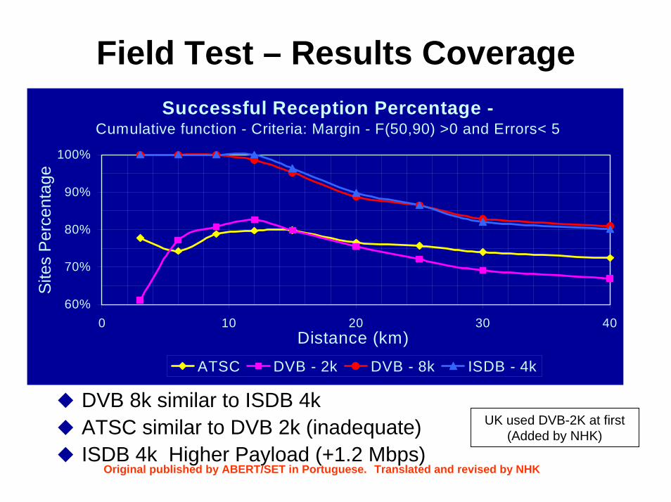
Field Test – Results Coverage
DVB 8k similar to ISDB 4kATSC similar to DVB 2k (inadequate)ISDB 4k Higher Payload (+1.2 Mbps)
Successful Reception Percentage - Cumulative function - Criteria: Margin - F(50,90) >0 and Errors< 5
60%
70%
80%
90%
100%
0 10 20 30 40Distance (km)
Site
s P
erce
ntag
e
ATSC DVB - 2k DVB - 8k ISDB - 4k
Original published by ABERT/SET in Portuguese. Translated and revised by NHK
UK used DVB-2K at first (Added by NHK)

2.3 Protection ratio
Protection ratio is very important factor for channel planning.
In Japan, also protection ratio was examined in early stage of digitalization, in 1998.
The detail data is attached on DiBEG homepage.
I will explain technical details of these data.
(see for detail data “”Protection ratio experiment and result”)
3. 3. Key technology for improvement ofKey technology for improvement ofISDBISDB--T transmission characteristicsT transmission characteristics(transmitter and micro(transmitter and micro--wave relay)wave relay)
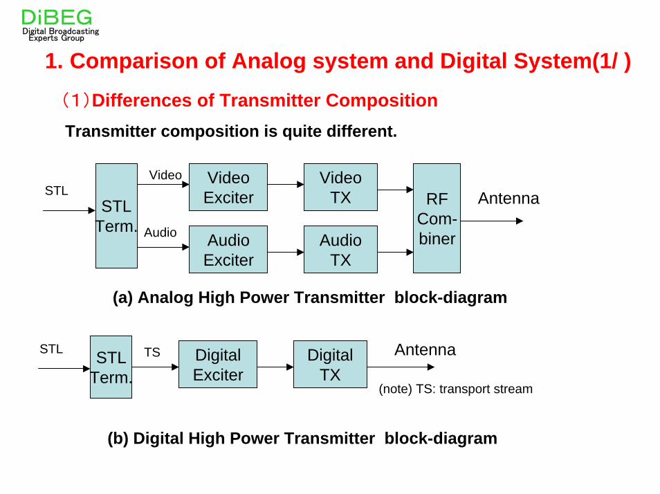
1. Comparison of Analog system and Digital System(1/ )(1)Differences of Transmitter CompositionTransmitter composition is quite different.
VideoExciter
AudioExciter
STLTerm.
STLVideo
Audio
VideoTX
AudioTX
RFCom-biner
(a) Analog High Power Transmitter block-diagram
STLTerm.
STL DigitalExciter
DigitalTX
Antenna
Antenna
(b) Digital High Power Transmitter block-diagram
TS
(note) TS: transport stream
DiBEGDigital Broadcasting
Experts Group
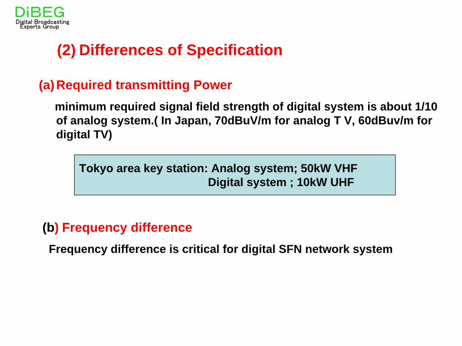
(2) Differences of Specification
(a)Required transmitting Powerminimum required signal field strength of digital system is about 1/10 of analog system.( In Japan, 70dBuV/m for analog T V, 60dBuv/m for digital TV)
Tokyo area key station: Analog system; 50kW VHF Digital system ; 10kW UHF
(b) Frequency differenceFrequency difference is critical for digital SFN network system
DiBEGDigital Broadcasting
Experts Group

OFDM signal
One of frequency Division multiplex
system
Transmission band
3rd order inter-modulationproducts are fallen into
adjacent channel
Orthogonal Frequency Division Multiplex
(c) Non-linear distortionIn digital system Non-linear distortion of transmitter causes the inter-modulation products, and these products are fallen into the adjacent sub-channels. Therefore signal quality is degraded by the Inter-carrier interference.
3rd order inter-modulation products
Spectrum of OFDM
DiBEGDigital Broadcasting
Experts Group

0.0001
0.001
0.01
0.1
20 25 30 35C/N(dB)
BER
linear
type B
type C
Inter-modulation products are fallen into adjacent sub-channels. These products behave as thermal noise, therefore BER characteristics are degraded.
Signal degradation caused by non-linear distortion
DiBEGDigital Broadcasting
Experts Group
Linear
25C/N(dB)
Low distortion
High distortion
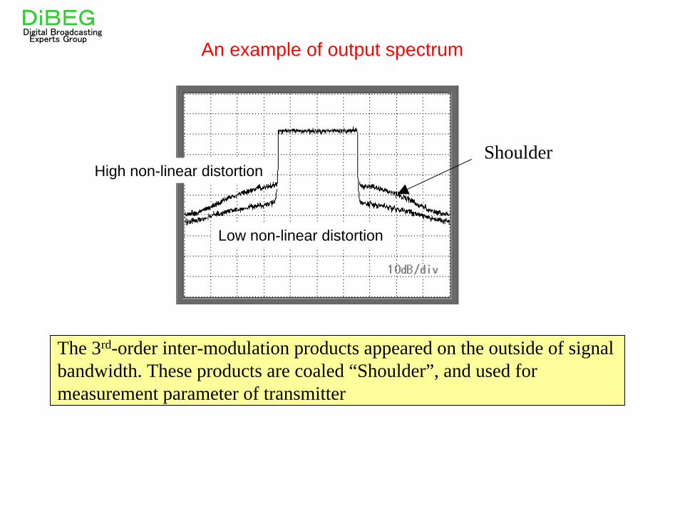
The 3rd-order inter-modulation products appeared on the outside of signal bandwidth. These products are coaled “Shoulder”, and used for measurement parameter of transmitter
ShoulderHigh non-linear distortion
An example of output spectrumDiBEGDigital Broadcasting
Experts Group
Low non-linear distortion
+OFDMMOD
LocalOscillator
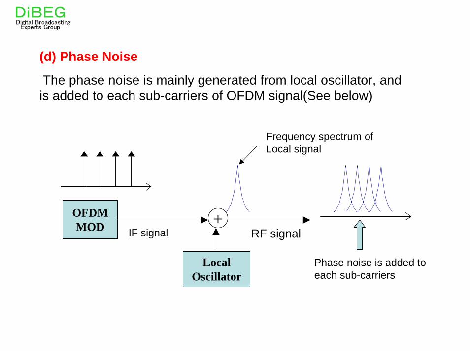
(d) Phase Noise
The phase noise is mainly generated from local oscillator, and is added to each sub-carriers of OFDM signal(See below)
IF signal RF signal
DiBEGDigital Broadcasting
Experts Group
Frequency spectrum of Local signal
Phase noise is added to each sub-carriers
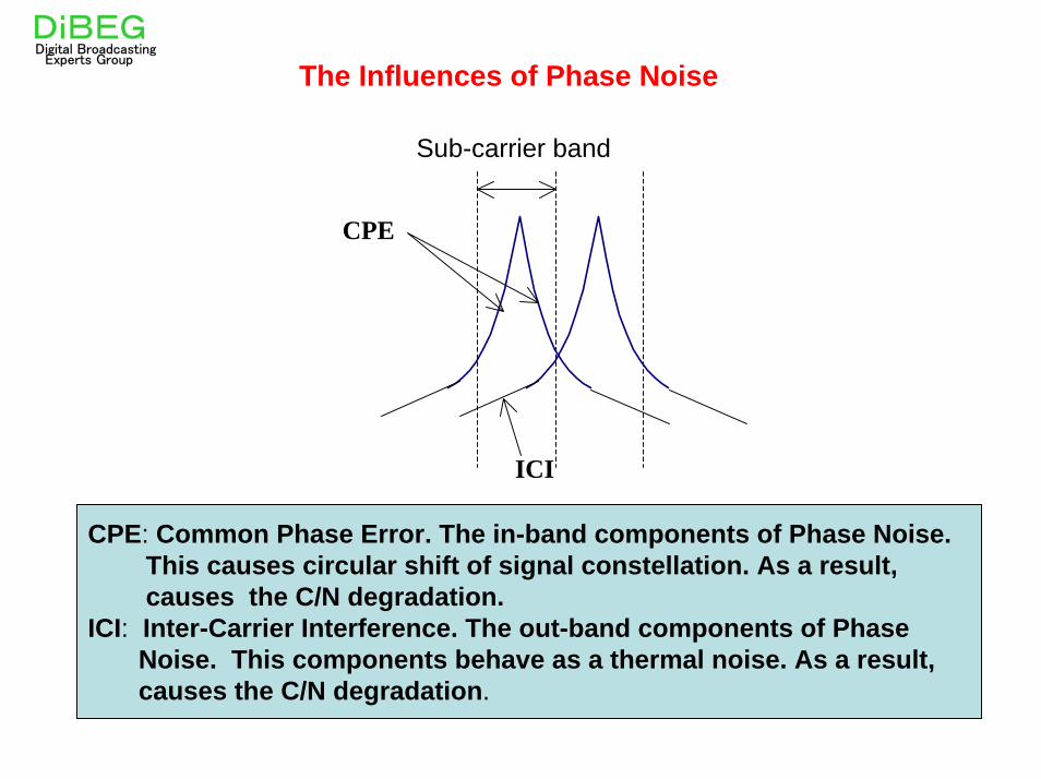
ICI
CPE
The Influences of Phase Noise
Sub-carrier band
CPE: Common Phase Error. The in-band components of Phase Noise.This causes circular shift of signal constellation. As a result, causes the C/N degradation.
ICI: Inter-Carrier Interference. The out-band components of Phase Noise. This components behave as a thermal noise. As a result, causes the C/N degradation.
DiBEGDigital Broadcasting
Experts Group

4. 4. Key technology for improvement ofKey technology for improvement ofISDBISDB--T transmission characteristicsT transmission characteristics
(Broadcast relay station and reception)(Broadcast relay station and reception)
In this section, we introduce the key technologies for broadcast relay station and reception.
The whole pages of this section are dedicated by NHK laboratory.

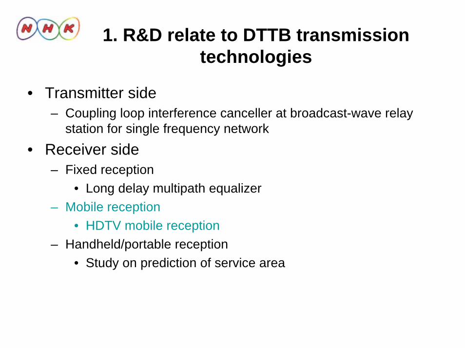
1. R&D relate to DTTB transmission technologies
• Transmitter side– Coupling loop interference canceller at broadcast-wave relay station
for single frequency network
• Receiver side– Fixed reception
• Long delay multipath equalizer– Mobile reception
• HDTV mobile reception– Handheld/portable reception
• Study on prediction of service area
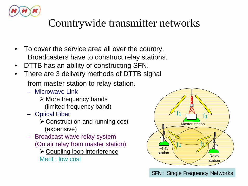
Countrywide transmitter networks
• To cover the service area all over the country,Broadcasters have to construct relay stations.
• DTTB has an ability of constructing SFN.• There are 3 delivery methods of DTTB signal
from master station to relay station.– Microwave Link
More frequency bands(limited frequency band)
– Optical FiberConstruction and running cost(expensive)
– Broadcast-wave relay system(On air relay from master station)
Coupling loop interferenceMerit : low cost
Master station
Relaystation
Relaystation
f1
f1 f1
f1
SFN : Single Frequency Networks

CLI canceller for broadcast-wave relay system-Toward the construction of countrywide digital terrestrial broadcasting
networks -
• Constructing stable and cost-effective relay networks is important.
• Broadcast-wave relay system is the most cost-effective signal delivery system.
• Remaining problem was stability. But we developed Coupling loop interference (CLI) canceller.
• CLI cancellers can eliminate distortion when signals are relayed in a single frequency network (SFN).
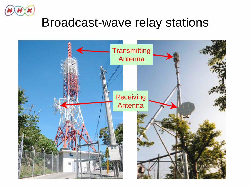
Broadcast-wave relay stations
ReceivingAntenna
TransmittingAntenna
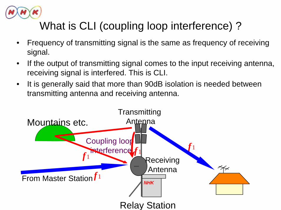
What is CLI (coupling loop interference) ?• Frequency of transmitting signal is the same as frequency of receiving
signal.• If the output of transmitting signal comes to the input receiving antenna,
receiving signal is interfered. This is CLI.• It is generally said that more than 90dB isolation is needed between
transmitting antenna and receiving antenna.
Coupling loop interference
Relay Station
Mountains etc.
NHK
ReceivingAntenna
Transmitting Antenna
f1f1
f1From Master Station
f1
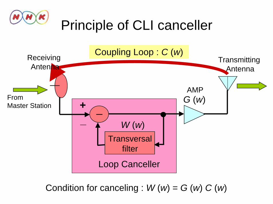
Principle of CLI canceller
Loop Canceller
Condition for canceling : W (w) = G (w) C (w)
+_
_W (w)
G (w)
Coupling Loop : C (w)
From Master Station
Transmitting Antenna
Transversalfilter
Receiving Antenna
AMP
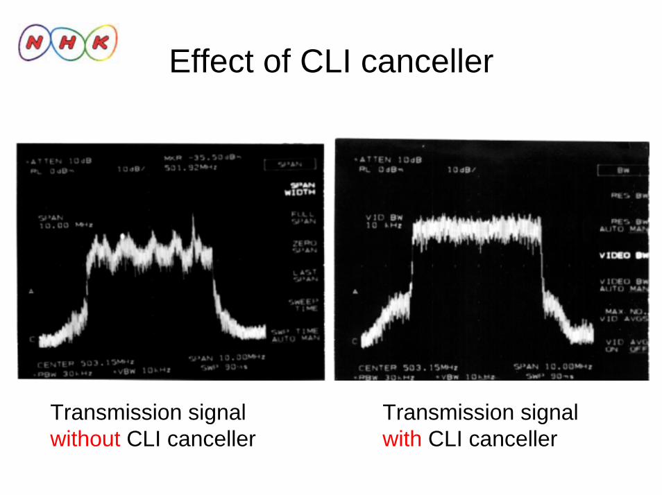
Effect of CLI canceller
Transmission signal without CLI canceller
Transmission signalwith CLI canceller
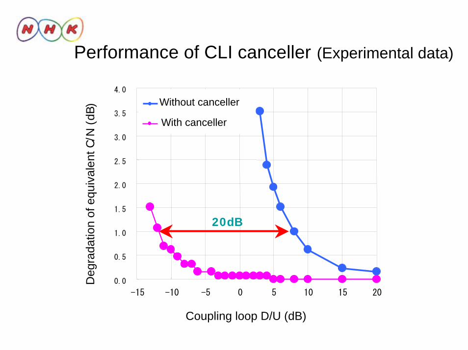
Performance of CLI canceller (Experimental data)
0.0
0.5
1.0
1.5
2.0
2.5
3.0
3.5
4.0
-15 -10 -5 0 5 10 15 20
Coupling loop D/U (dB)
Deg
rada
tion
of e
quiv
alen
t C/N
(dB
) Without canceller
With canceller
20dB

Equipment of CLI canceller (small type)
RF/IF, IF/RF freq. transform
Loopcanceller

1. R&D relate to DTTB transmission technologies
• Transmitter side– Coupling loop interference canceller at broadcast-wave
relay station for single frequency network
• Receiver side– Fixed reception
• Long delay multipath equalizer– Mobile reception
• HDTV mobile reception– Handheld/portable reception
• Study on prediction of service area
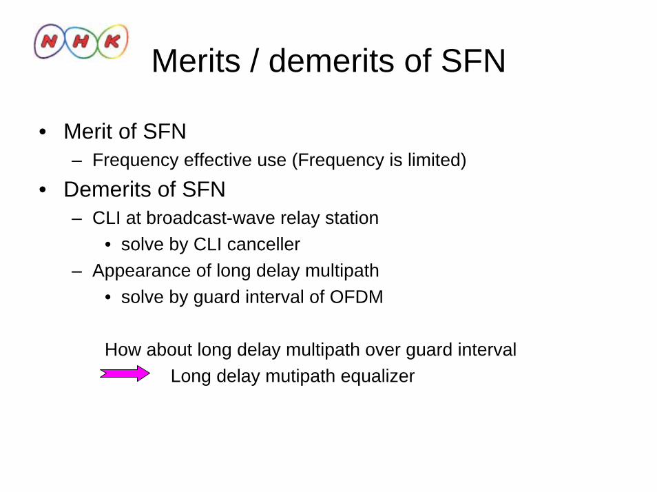
Merits / demerits of SFN
• Merit of SFN– Frequency effective use (Frequency is limited)
• Demerits of SFN– CLI at broadcast-wave relay station
• solve by CLI canceller– Appearance of long delay multipath
• solve by guard interval of OFDM
How about long delay multipath over guard intervalLong delay mutipath equalizer
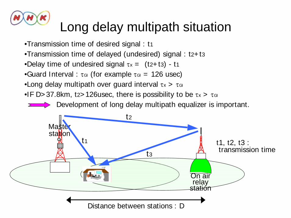
Long delay multipath situation
Masterstation
On air relay
station
t1
t2
t3t1, t2, t3 : transmission time
•Transmission time of desired signal : t1•Transmission time of delayed (undesired) signal : t2+t3•Delay time of undesired signal τx = (t2+t3) - t1•Guard Interval : τGI (for example τGI = 126 usec)•Long delay multipath over guard interval τx > τGI
•IF D>37.8km, t2>126usec, there is possibility to be τx > τGI
Development of long delay multipath equalizer is important.
Distance between stations : D
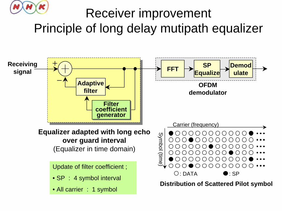
Equalizer adapted with long echo over guard interval
(Equalizer in time domain)
Receiver improvementPrinciple of long delay mutipath equalizer
: DATA : SP
Carrier (frequency)S
ymbol (tim
e)
Distribution of Scattered Pilot symbol
Receiving signal
OFDM demodulator
FFT SPEqualize
Demodulate
+
Filter coefficient generator
Filter coefficient generator
Adaptivefilter
-
Update of filter coefficient ;
• SP : 4 symbol interval
• All carrier : 1 symbol
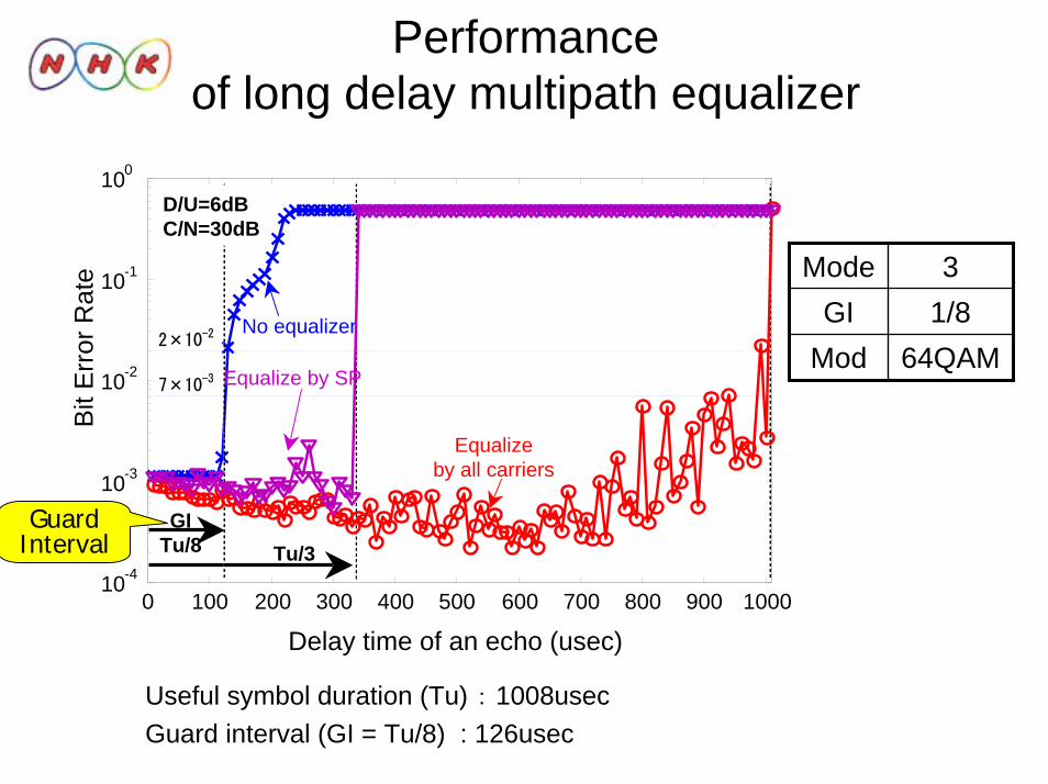
Performance of long delay multipath equalizer
64QAMMod1/8GI3Mode
Useful symbol duration (Tu) : 1008usecGuard interval (GI = Tu/8) : 126usec
0 100 200 300 400 500 600 700 800 900 100010-4
10-3
10-2
10-1
100
2×10⁻²
7×10⁻³
Equalize by all carriers
No equalizer
Tu/3
D/U=6dBC/N=30dB
GITu/8
Equalize by SP
Delay time of an echo (usec)
Bit
Err
or R
ate
GuardInterval
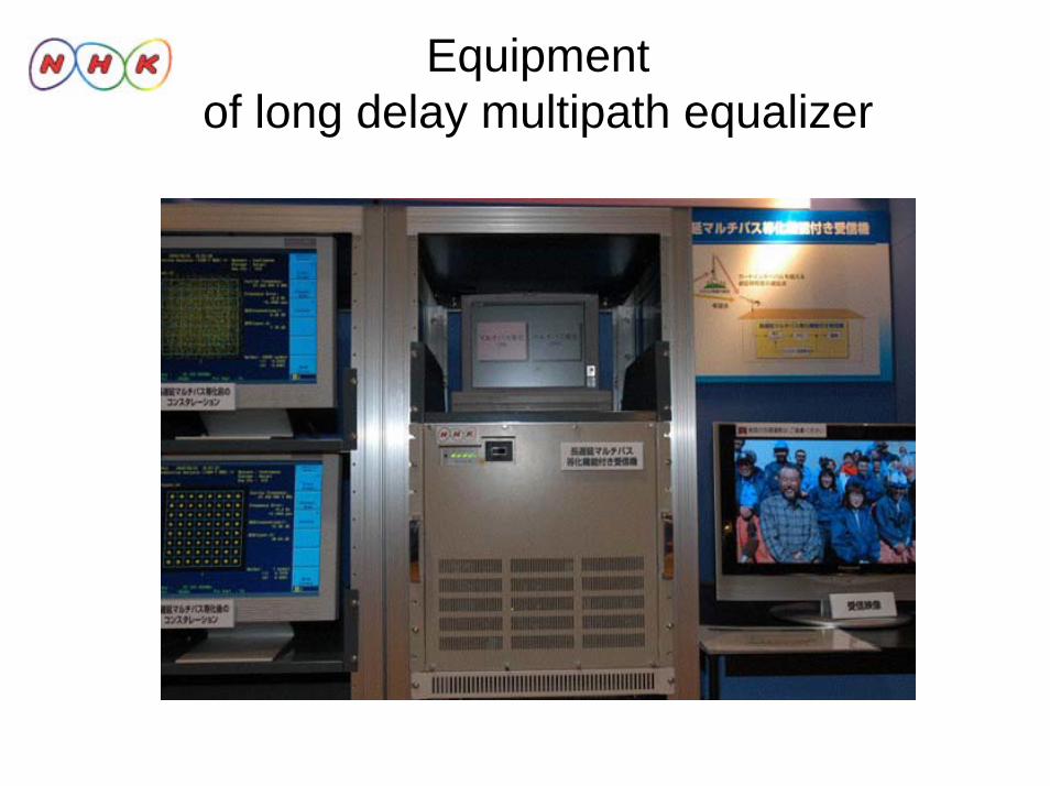
Equipmentof long delay multipath equalizer
1. R&D relate to DTTB transmission technologies
• Transmitter side– Coupling loop interference canceller at broadcast-wave relay
station for single frequency network
• Receiver side– Fixed reception
• Long delay multipath equalizer– Mobile reception
• HDTV mobile reception– Handheld/portable reception
• Study on prediction of service area
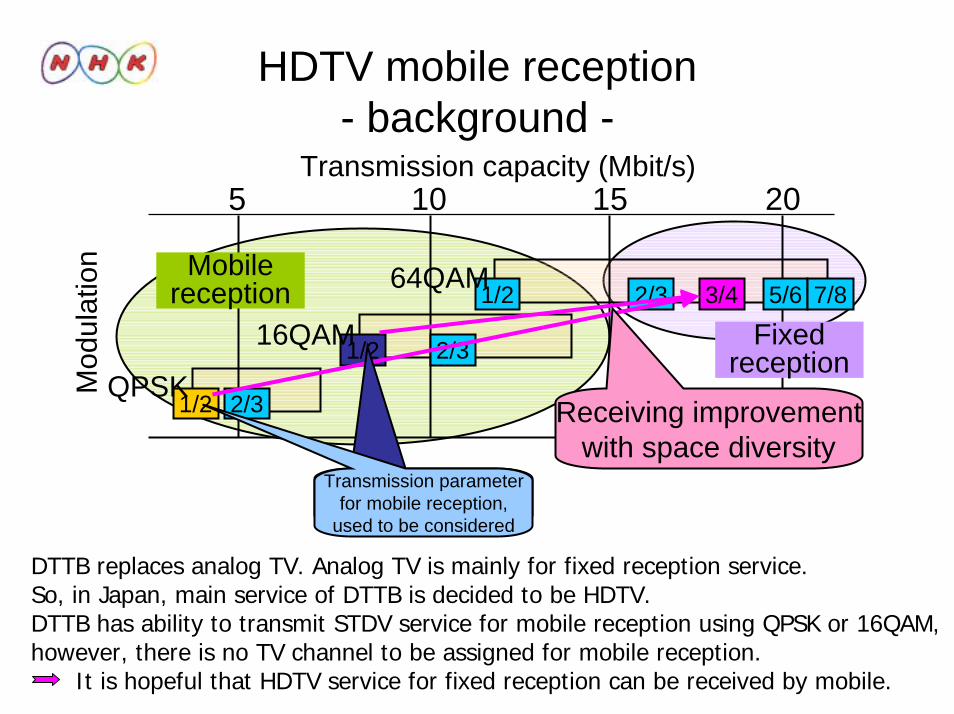
HDTV mobile reception- background -
5 10 15 20
1/2 2/3
1/2 2/3
1/2 2/3 3/4 5/6 7/864QAM
16QAM
QPSK
Transmission capacity (Mbit/s)
Fixed reception
Mobilereception
Receiving improvementwith space diversity
Transmission parameterfor mobile reception,
used to be considered
Mod
ulat
ion
DTTB replaces analog TV. Analog TV is mainly for fixed reception service.So, in Japan, main service of DTTB is decided to be HDTV. DTTB has ability to transmit STDV service for mobile reception using QPSK or 16QAM,however, there is no TV channel to be assigned for mobile reception.
It is hopeful that HDTV service for fixed reception can be received by mobile.

HDTV mobile reception system4-branch space diversity
• HDTV mobile reception system– Signal : 6MHz BW 64QAM-OFDM (ISDB-T)– Application : HDTV (18.3 Mbps) in a mobile car– Diversity : 4-branch space diversity
• Implementation and performance evaluation– Laboratory test
• Maximum Doppler frequency in fading environment– Field trial in Tokyo suburban area

Principle of 4-branch space diversity
for OFDM signal under mobile reception
Derived from the frequency response, based on the received Scattered Pilot (SP) signal of OFDM
Spectra ofOFDM signal
Weighting factor
・・・
・・・
FFT#1
D(0)
D(i)
D(k-1)
FFT#2
FFT#3
FFT#4
01 2 3 ・・・・・・・・・ k carrier
#1
#2
#3
#4
Output
Branch
Block diagram of diversity reception system
C1(0)
C1(k-1)
C2(0)
C2(k-1)
C3(0)
C3(k-1)
C4(0)
C4(k-1)
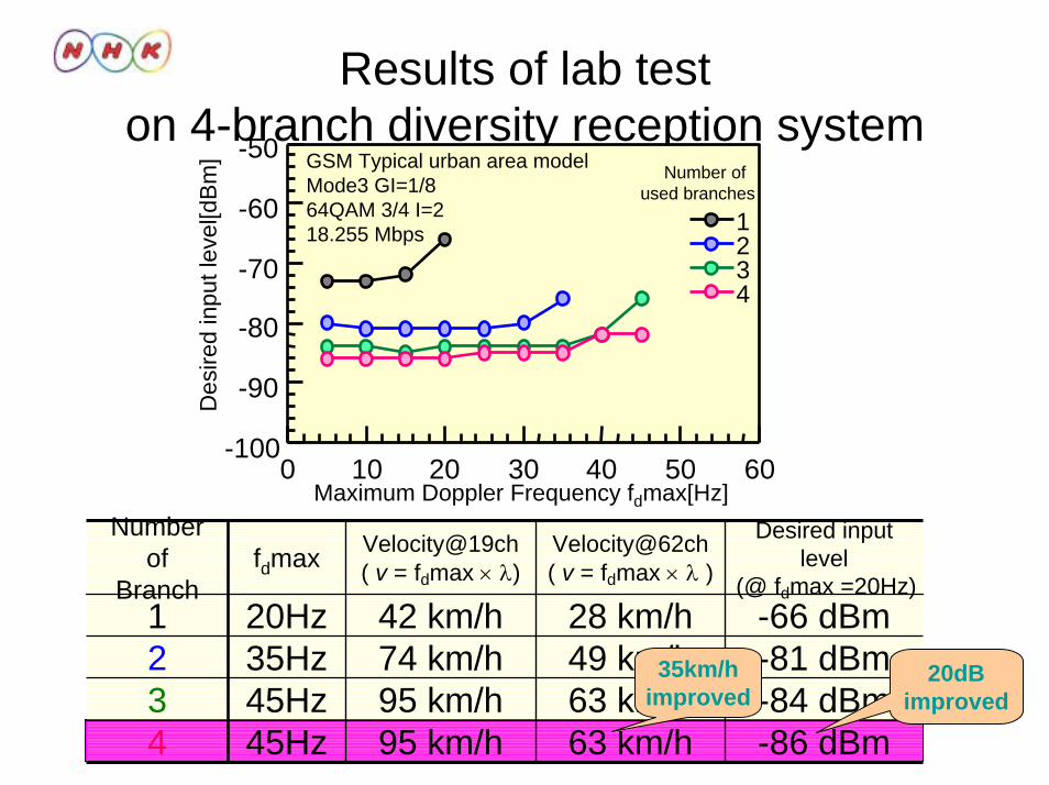
Results of lab test on 4-branch diversity reception system
Des
ired
inpu
t lev
el[d
Bm
]
Maximum Doppler Frequency fdmax[Hz]0 10 20 30 40 50 60
-100
-90
-80
-70
-60
-50
1234
Number of used branches
GSM Typical urban area modelMode3 GI=1/864QAM 3/4 I=218.255 Mbps
-86 dBm-84 dBm-81 dBm-66 dBm
Desired input level
(@ fdmax =20Hz)
63 km/h95 km/h45Hz349 km/h74 km/h35Hz2
63 km/h95 km/h45Hz4
28 km/h42 km/h20Hz1
Velocity@62ch( v = fdmax × λ )
Velocity@19ch( v = fdmax × λ)fdmax
Number of
Branch
20dBimproved
35km/himproved
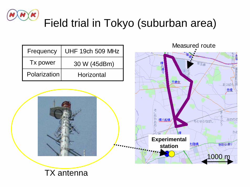
Field trial in Tokyo (suburban area)
HorizontalPolarization
Tx power
UHF 19ch 509 MHzFrequency
30 W (45dBm)
TX antenna
Experimental station
1000 m
Measured route
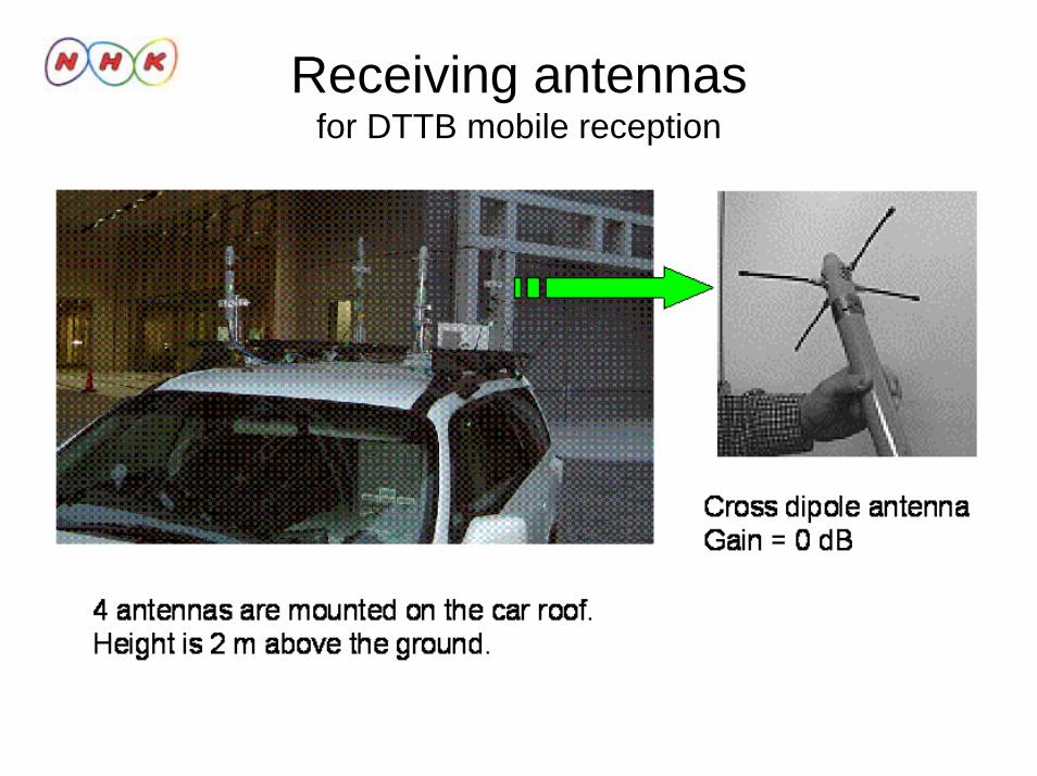
Receiving antennasfor DTTB mobile reception
40 45 50 55 60 65 70 75 800
20
40
60
80
100
Mode3 GI=1/864QAM 3/4 I=2
Number ofused branches
1234
Electric field strength[dBuV/m]
Perc
enta
ge o
f suc
cess
on re
ceiv
ing[
%]
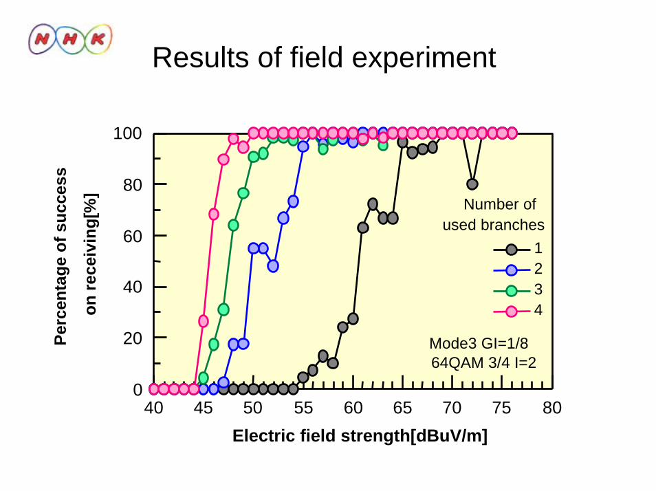
Results of field experiment
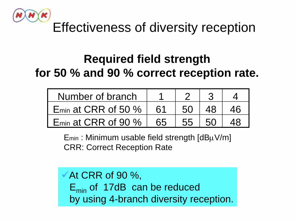
Effectiveness of diversity reception
Emin : Minimum usable field strength [dBµV/m]CRR: Correct Reception Rate
48505565Emin at CRR of 90 %46485061Emin at CRR of 50 %4321Number of branch
Required field strength for 50 % and 90 % correct reception rate.
At CRR of 90 %,Emin of 17dB can be reducedby using 4-branch diversity reception.

1. R&D relate to DTTB transmission technologies
• Transmitter side– Coupling loop interference canceller at broadcast-wave relay
station for single frequency network
• Receiver side– Fixed reception
• Long delay multipath equalizer– Mobile reception
• HDTV mobile reception– Handheld/portable reception
• Study on prediction of service area
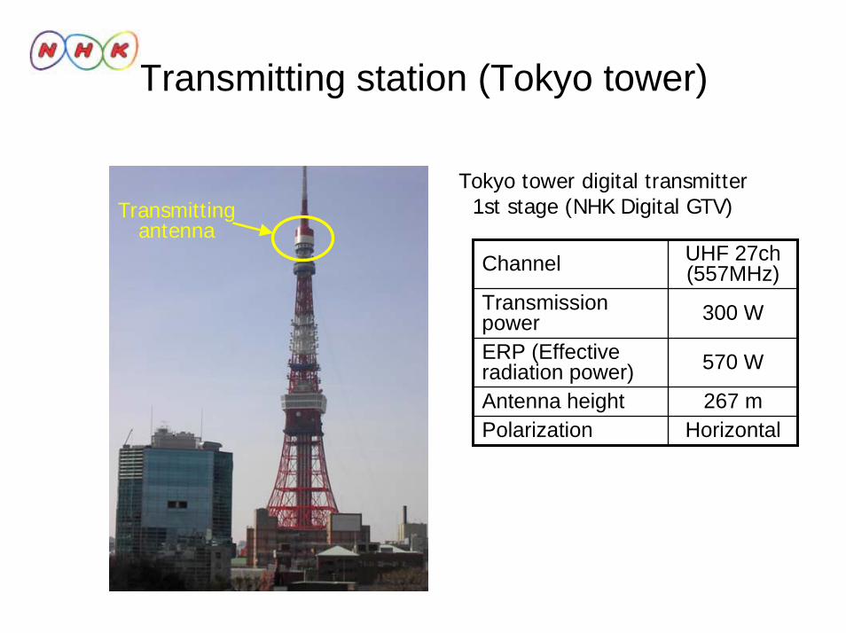
Transmitting station (Tokyo tower)
UHF 27ch(557MHz)Channel
HorizontalPolarization267 mAntenna height
570 WERP (Effective radiation power)
300 WTransmission power
Tokyo tower digital transmitter1st stage (NHK Digital GTV)Transmitting
antenna

Transmission parameters and receiving scenery
B
215ms3/4
64QAM
12A1Number of segments
QPSKCarrier modulation
1/2FEC coding rate215msTime interleaving
3(5617 carriers)Mode
2 layersHierarchical transmission
1/8(126usec)GI (Guard Interval)
Transmission parameters of NHK Digital GTV
HDTVProgram
5.6 MHz
SinpleVideo
Program
AB B
Receiving Antenna
1.5 m
Receiving scenery
Receiving antenna height : 1.5mReceiving antenna : Cross dipole antenna
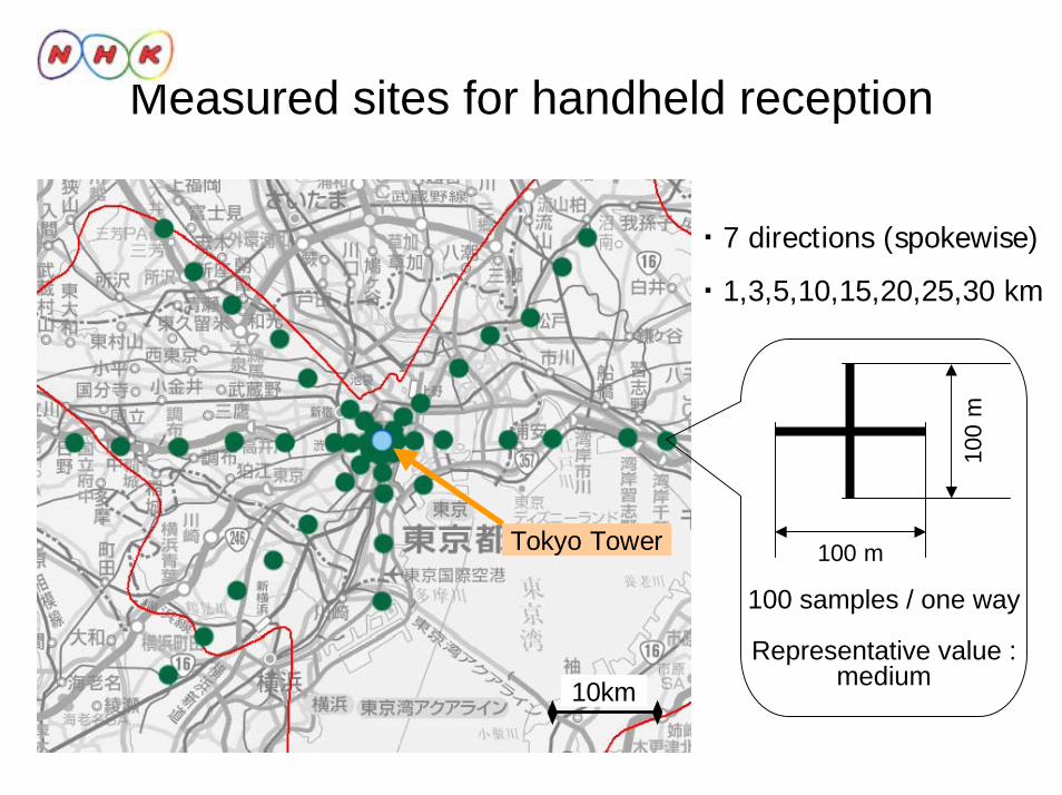
Measured sites for handheld reception
Tokyo Tower
10km
・7 directions (spokewise)
・1,3,5,10,15,20,25,30 km
100
m
100 m
100 samples / one way
Representative value :medium
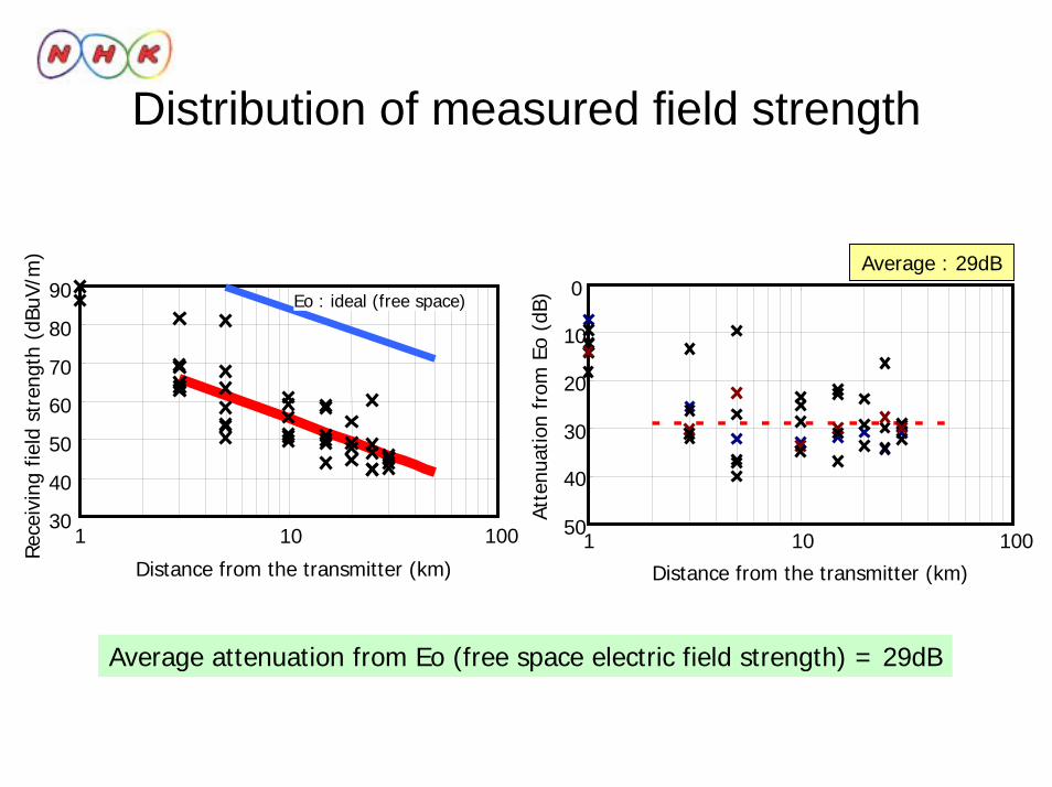
Distribution of measured field strength
30
40
50
60
70
80
90
1 10 100
Distance from the transmitter (km)
Rec
eivi
ng f
ield
str
engt
h (d
BuV/
m)
Eo : ideal (free space)
Average : 29dB0
10
20
30
40
501 10 100
Distance from the transmitter (km)
Atte
nuat
ion
from
Eo
(dB)
Average attenuation from Eo (free space electric field strength) = 29dB
Thank you for your attention !
END of seminar #5