issn 2348 – 7968 effect of thermal and mechanical …ijiset.com/v1s9/ijiset_v1_i9_50.pdfeffect of...
TRANSCRIPT

IJISET - International Journal of Innovative Science, Engineering & Technology, Vol. 1 Issue 9, November 2014.
www.ijiset.com
ISSN 2348 – 7968
Effect of Thermal and Mechanical Loads On A Non Parallel Face Flanges Using Finite Element Analysis
W.E. Abdel-Ghany 1, S.J. Ebeid 2 and Mohamed Salama 3
1, 2 Department of Design and Production Engineering.
Faculty of Engineering, Ain Shams University, Cairo, EGYPT
3 Senior Technical Office Engineer, El-Sewedy Electric, Cairo, EGYPT
Abstract The flanged joint is one of the weakest elements on the piping system because of leakage. The leakage free joint is the target of the standard codes and many analytical and experimental studies. The codes usually focus on the conventional flanged joints containing gaskets. The gasketed joint which is classified in the standard codes was studied under different operating conditions to investigate its performance and its sealing capability. The non-parallel face flanged joint has been studied under different mechanical loads to be developed and it showed high efficiency than the conventional joint. The present paper studies the non-parallel face flanges as a 3D finite element model to investigate the behaviour of the joint under combined mechanical and thermal loading. The suggested model for the joint was established for different flange thicknesses under various operating temperatures and internal pressures. Keywords: Flanges; Non Parallel Face Flanges; Finite Element Analysis; Coupled Temperature-Displacement; Thermal loading.
1. Introduction
The well-known problem of flanged joints is the leakage control. Researches of previous studies aimed for the optimum sealing conditions of the joint by looking for the effective dimensions, loads and the stress concentration areas. The gasket is usually the main problem facing the joint as it is the weakest part. The present work is directed to non-gasket joints. The full face metal-to-metal contact flanges are used in high pressure situations and also when it is desirable to install a compact arrangement for a pipe and its flange [1]. D.H. Nash and J. Spence studied the metal-to-metal contact flanges to optimize the flange dimensions and to get the effective bolt loading. They found that with higher bolt loading, higher sealing effects were achieved. A comparative study between the conventional and non-conventional flange joints was established by M. Abid and
D.H. Nash [2]. They found that the non-gasket joint was better than the gasket one. M. Abid and D.H. Nash [3] also studied the full face metal-to-metal contact flange to find the optimum face angle for the best sealing conditions, where an optimum face angle of +0.03° was found. A 3D study was established by M. Abid [4] for gasketed flanges to find the safe operating conditions under internal pressure and temperature. They found that with higher temperatures, the pressure must be lowered for safe operating conditions. In most of the previous studies, the joint was simplified to be a 2D model and the bolt was considered as a ring around the flange being fixed from its base. The second flange was removed and replaced by a contact plate which was fixed in all directions. It was assumed that there was no clearance between the bolt and its hole. Also a frictionless element was considered. M. Couchaux, M. Hjiaj, I. Ryan1 and A. Bureau [5] studied the flanged joint as a 3D model under a tensile force over the pipe cross sectional area without investigating the bolt preload. The joint was modeled with a contact interaction and the friction between the parts was taken into consideration. From that study it is found that, the prying action increases when the ratio between the flange rigidity and the bolt rigidity becomes high. In case of thicker flanges the prying force is concentrated at the flange edges. Chavan U. S, Dharkunde R. B and Dr. Joshi S.V [6], studied the joint under bolt preloading, internal pressure and hydrostatic pressure. They found that the maximum stress on the flange was obtained at the inside face of the flange near the gasket seating step and that it increases within the increase in the flange thickness. The maximum compressive stress in the gasket is obtained at the outer gasket face. The gasket performance decreases with the decrease in flange thickness. The study found that the flange thickness has considerable effect on the flange strength and gasket performance. Zasiah Tafheem and Khan Mahmud Amanat [7] established a 3D model for the flanged joint under bending load and
327
IJISET - International Journal of Innovative Science, Engineering & Technology, Vol. 1 Issue 9, November 2014.
www.ijiset.com
ISSN 2348 – 7968
bolt pretension only. They found that the flange thickness affects the bolt tension. The bolt tension decreases as the flange width increases for any pipe diameter, bolt number, bolt diameter and flange thickness. Also the bolt tension increases as the diameter of the bolt increases for any pipe diameter, bolt number, flange width and thickness. W.E. Abdel-Ghany, S.J. Ebeid and Mohamed Salama [8] studied the metal-to-metal contact flange as a 3D finite element model under bolt loading and internal pressure to obtain the optimum flange design considering thickness and found that the optimum bolt loading achieving 80% of bolt stress. The study also showed that with the increase of bolt loading the flange stress increases and the flange displacement decreases. Nomenclature
σy: Yield Strength MPa. E: Modulus of Elasticity GPa. ρ: Density Kg/m³. ν: Poisson’s Ratio. α : Thermal Expansion mm/mm. ˚C.
: Specific Heat J/Kg. ˚C. : Thermal Conductivity W/m. ˚C
2. Model Geometry
The metal-to-metal non-gasketed flanged joint consists of three parts, namely; flange, bolt and pipe. The flange size is 4 inch in the nominal bore class 900# according to ASME B16.5 [9]. The flange thickness is 30 mm and its hub length is 34 mm. while the bolt spacing requirements round the bolt circle, bolt center-to-center equals three times the bolt diameter. A sum of 16 bolts size M10 are used in the joint on a bolt circle diameter of 146 mm [Table 1]. The present work examines the joint performance under loading of internal pressure and temperature to achieve the most optimum conditions for the joint. The model used has the following conditions: the bolt preload is 80% as a constant value for different flange thicknesses, while the flange thickness varies from 15 mm to 35 mm with a step of 5 mm and the temperature varies from 100 to 500 C with a step of 100 C. For each temperature the joint operating pressure changes according to ASME 16.5. In all cases the maximum stresses and flange displacement will be determined. The joint performance under operating conditions of internal pressure and temperature can be investigated from the finite element model results. A total of five different operating temperatures were examined for five flange thickness values, making a total of twenty five different cases.
TABLE.1 Joint parameters
Joint Fixed Parameters
Flange internal diameter mm 87.3
Flange external diameter mm 171
Pipe thickness mm 13.5
Bolt circle diameter mm 146
Flange hub thickness mm 15.5
Flange hub length mm 34
Bolt diameter mm 10
Number of bolts 16
Joint Variable Parameters
Flange Thickness Pressure-Temperature Ratings
mm Temperature C Pressure MPa
15 100 13.98
20 200 13.14
25 300 11.95
30 400 10.42
35 500 3.53
3. Material Properties
The yield stress of the flange and pipe material is shown below in Tables 2, 3 and 4 according to ASME II code [10] for both the bolt and the flange material. The material properties depend on the temperature.
Table.2 Physical Properties
Part ρ
Kg/m³
ν α
mm/mm.˚C
Cp
J/Kg.˚C
Flange and Pipe
7860 0.3 12.5e-6 448
Bolt 7750 0.3 14.1e-6 486
328
IJISET - International Journal of Innovative Science, Engineering & Technology, Vol. 1 Issue 9, November 2014.
www.ijiset.com
ISSN 2348 – 7968
Table.3 Material properties
Temperature
C
Bolt Flange and Pipe
Yield Strength
MPa
Elasticity GPa
Yield Strength
MPa
Elasticity GPa
25 655 195 248 202
100 537 189 227 196
150 489 186 219 195
200 454 183 213 192
250 428 179 204 189
300 408 176 194 185
350 391 172 177 179
400 375 169 166 171
450 362 165 158 162
500 349 160 150 151
Table.4 Physical Properties
Temperature
C Bolt Flange and
Pipe
Tc W/m.˚C Tc W/m.˚C
20 14.1 47.3
50 14.6 47.9
75 15.4 48
100 15.7 47.9
125 16.1 47.6
175 16.5 46.7
200 16.8 46.1
225 17.2 45.5
250 17.6 44.8
275 17.9 44.2
300 18.3 43.5
325 18.7 42.9
350 19 42.2
375 19.4 41.5
400 19.7 40.9
425 20..1 40.2
450 20.5 39.4
475 20.8 38.6
500 21.2 37.8
525 21.5 36.9
4. Finite Element Model
The present paper, studies the metal-to-metal contact flanges as a 3D FE model using ABAQUS 6.10 software. The simplifications in the previous studies will be avoided in this model except that the bolt will be considered as cylindrical shank with a bolt angle of 22.5. In many previous studies, the model was a 2D model axisymmetric that considered the bolt as a ring being fixed on its base in all directions. The bolt hole has no clearance with the bolt shank. The second flange is replaced by a contact plate which is fixed in all directions with complete contact to the flange face. In addition there is contact between the bolt head and the flange surface. The friction between all parts was neglected. The established model, created as a 3D axisymmetric model considers a sector of the joint with an angle of 11.25 containing only half the bolt and sector of the joint. The solid model is created as two flanges connected together by bolts. The model operates under internal pressure and temperature, where the hydrostatic pressure is generated due to the closed system. The friction between the two flanges and between the flange and the bolt head and shank was applied in the contact between the surfaces. The joint is assembled at first using the bolts being under bolt pre-stress after which the fluid is pressurized in the system. The joint is loaded in two steps in order to simulate the actual loading conditions; the first is due to the bolt tightening and the second is due to the internal pressure and temperature. The present model can investigate the stress concentration area, the flange deformation and also the effect of temperature on the joint performance. The flanged joint model is closed from the two ends with end caps to represent the actual system, where the hydrostatic pressure is generated due to the internal pressure and the system enclosure. The model is established to use elastic-plastic material properties. The bolt hole diameter is 11 mm with a 1 mm clearance with the bolt shank. The second step of loading is a coupled temperature-displacement step [11], where the pressure loading and temperature can be applied together to the model. The temperature can be applied on the model using the Film Condition option, where the internal fluid will be applied as a skin of fluid on the inner joint surface with a convection heat transfer coefficient of 150 W/m² ˚C. The skin of the outer fluid on the joint outer surface is considered to be with a convection heat transfer coefficient of 20 W/m² ˚C. The temperature loading will be considered to act as a steady state condition.
329

IJISET - International Journal of Innovative Science, Engineering & Technology, Vol. 1 Issue 9, November 2014.
www.ijiset.com
ISSN 2348 – 7968
4.1 Element Selection
The element used in the model could be selected from the ABAQUS element library according to the modeling and the analysis type. The element used in the present model is C3D8RT [Figure. 1]. It is a solid cubic 3D element with 8 nodes. This element is used for a 3D coupled temperature displacement analysis with reduced integration and it is also used for all parts of the model. The elements are distributed and refined according to the stress concentration predictable areas.
Fig.1 Element shape
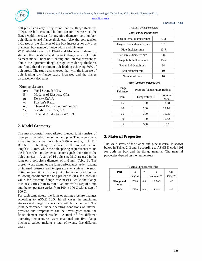
4.2 Contact Surfaces
Numerical modeling of any joint requires a realistic representation of the contact interaction between the different components in order to allow the load to be penetrated from one part of the model to the other. The contact formulation in ABAQUS consists of master and slave surfaces, where it is necessary to define one of the contact surfaces as master and the other as slave. So the nodes on the master surface cannot penetrate the slave surface nodes. It is of great importance to carefully assign the slave and master surfaces. The rule which is followed on the model is the finer the meshed surface so is the slave surface. This means that the bolt is finer than the flange and
the bolt will be the slave surface and the flange will be the master one. The contact interaction between the parts is used to define the relations between the contact surfaces. The thermal loads are needed to define the thermal property between the model parts and to allow for the transfer between the parts and each other. Without applying the thermal interaction between the contact surfaces, no heat will be able to transfer between those surfaces. However, simulating that interaction is very sensitive and difficult to achieve. The contact interaction property is in three forms: Normal, Tangential and Thermal behavior: • The normal behaviour is a hard contact pressure
enclosure with penalty standards. • The tangential behaviour is a penalty formulation with
a 0.2 coefficient of friction. • The contact surfaces separation is allowed according to
the model behaviour under the loading and its reactions.
• The thermal behaviour is defined as a film condition with the fluid heat transfer coefficient, where the film has a different temperature.
The highlighted surface represents the contact surfaces [Figure. 2(a)]. The bolt surface will be the master one and the flange surface will be the slave (bolt head and shank with the flange surfaces). • Contact between the bolt shank and the bolt hole
surface. • Contact between the bolt head and the flange upper
surface. • Contact between the two flange faces. • All the inner surface of the model will have the inner
film contact interaction property with its temperature (the inner fluid temperature) [Figure. 2(c)].
• All the outer surfaces of the model will have the outer film contact interaction property with its temperature (ambient temperature 20 C) [Figure. 2(d)].
330
IJISET - International Journal of Innovative Science, Engineering & Technology, Vol. 1 Issue 9, November 2014.
www.ijiset.com
ISSN 2348 – 7968
(a) Contact surfaces. (b) Model Mesh.
(c) Inner film surface. (d) Outer film surface.
Fig.2: (a) Contact surfaces. (b) Model Mesh. (c) Inner film surface. (d) Outer film surface.
4.3 Model Meshing
Eight node brick elements with reduced integration C3D8RT were considered for all the parts in the model [Figure.2 (b)]. The flange is meshed with hexagonal element shapes to have regular distribution. More mesh refinement is considered on the stress concentration area as the bolt hole circle and the flange fillet. These refinements are carried to improve the stress result. The meshing is also refined on the shank-to-head circle to improve the results on that area. The joint model is meshed to get the best results under the different loading conditions of the flange.
The contact surfaces are meshed carefully to improve the results.
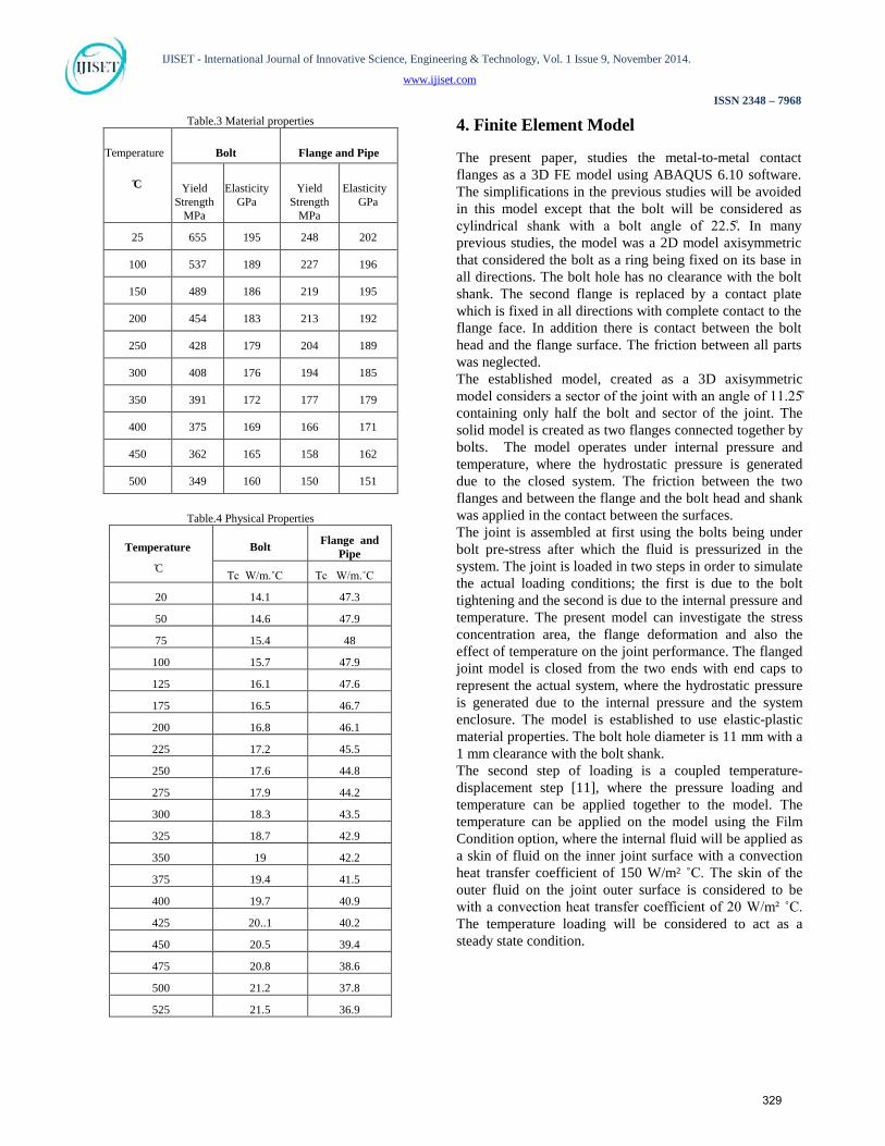
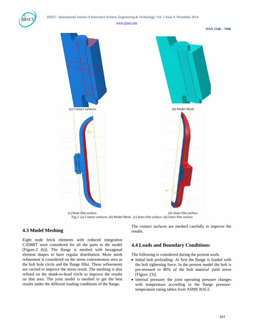
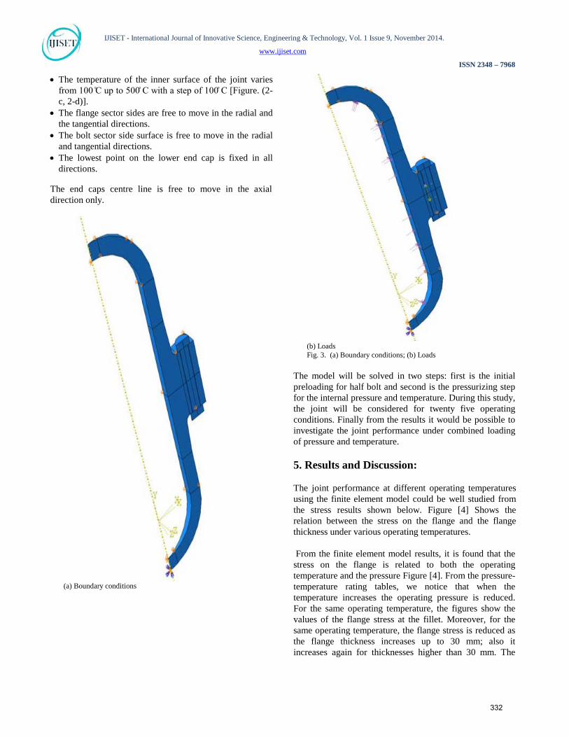
4.4 Loads and Boundary Conditions:
The following is considered during the present work: • Initial bolt preloading: At first the flange is loaded with
the bolt tightening force. In the present model the bolt is pre-stressed to 80% of the bolt material yield stress [Figure. (3)].
• Internal pressure: the joint operating pressure changes with temperature according to the flange pressure-temperature rating tables from ASME B16.5.
331
IJISET - International Journal of Innovative Science, Engineering & Technology, Vol. 1 Issue 9, November 2014.
www.ijiset.com
ISSN 2348 – 7968
• The temperature of the inner surface of the joint varies from 100 C up to 500 C with a step of 100 C [Figure. (2-c, 2-d)].
• The flange sector sides are free to move in the radial and the tangential directions.
• The bolt sector side surface is free to move in the radial and tangential directions.
• The lowest point on the lower end cap is fixed in all directions.
The end caps centre line is free to move in the axial direction only.
(a) Boundary conditions
(b) Loads Fig. 3. (a) Boundary conditions; (b) Loads
The model will be solved in two steps: first is the initial preloading for half bolt and second is the pressurizing step for the internal pressure and temperature. During this study, the joint will be considered for twenty five operating conditions. Finally from the results it would be possible to investigate the joint performance under combined loading of pressure and temperature.
5. Results and Discussion:
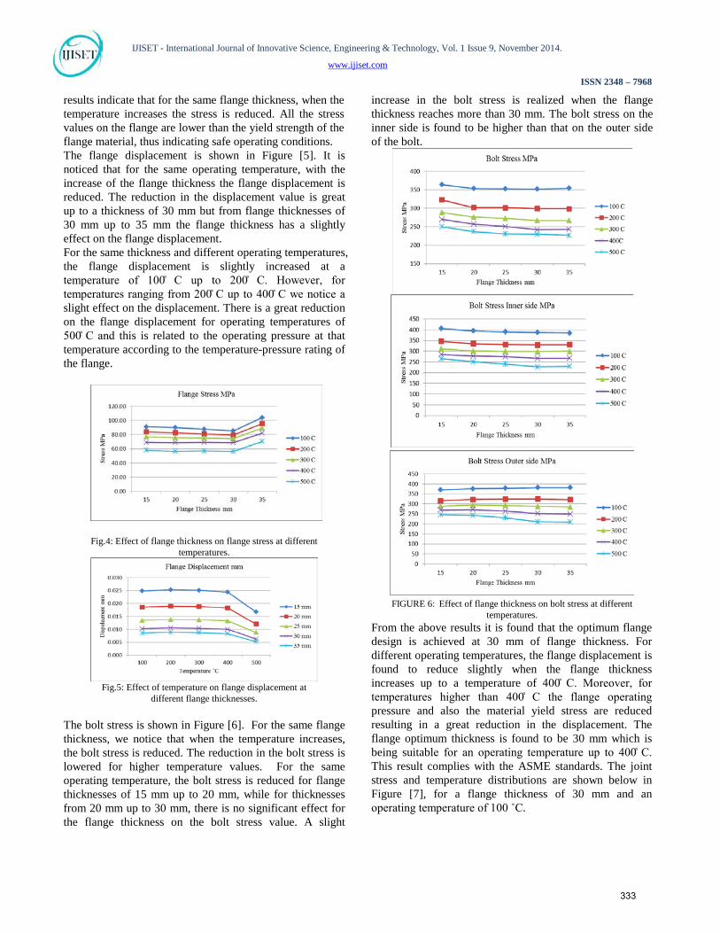
The joint performance at different operating temperatures using the finite element model could be well studied from the stress results shown below. Figure [4] Shows the relation between the stress on the flange and the flange thickness under various operating temperatures. From the finite element model results, it is found that the stress on the flange is related to both the operating temperature and the pressure Figure [4]. From the pressure-temperature rating tables, we notice that when the temperature increases the operating pressure is reduced. For the same operating temperature, the figures show the values of the flange stress at the fillet. Moreover, for the same operating temperature, the flange stress is reduced as the flange thickness increases up to 30 mm; also it increases again for thicknesses higher than 30 mm. The
332
IJISET - International Journal of Innovative Science, Engineering & Technology, Vol. 1 Issue 9, November 2014.
www.ijiset.com
ISSN 2348 – 7968
results indicate that for the same flange thickness, when the temperature increases the stress is reduced. All the stress values on the flange are lower than the yield strength of the flange material, thus indicating safe operating conditions. The flange displacement is shown in Figure [5]. It is noticed that for the same operating temperature, with the increase of the flange thickness the flange displacement is reduced. The reduction in the displacement value is great up to a thickness of 30 mm but from flange thicknesses of 30 mm up to 35 mm the flange thickness has a slightly effect on the flange displacement. For the same thickness and different operating temperatures, the flange displacement is slightly increased at a temperature of 100 C up to 200 C. However, for temperatures ranging from 200 C up to 400 C we notice a slight effect on the displacement. There is a great reduction on the flange displacement for operating temperatures of 500 C and this is related to the operating pressure at that temperature according to the temperature-pressure rating of the flange.
Fig.4: Effect of flange thickness on flange stress at different
temperatures.
Fig.5: Effect of temperature on flange displacement at
different flange thicknesses. The bolt stress is shown in Figure [6]. For the same flange thickness, we notice that when the temperature increases, the bolt stress is reduced. The reduction in the bolt stress is lowered for higher temperature values. For the same operating temperature, the bolt stress is reduced for flange thicknesses of 15 mm up to 20 mm, while for thicknesses from 20 mm up to 30 mm, there is no significant effect for the flange thickness on the bolt stress value. A slight
increase in the bolt stress is realized when the flange thickness reaches more than 30 mm. The bolt stress on the inner side is found to be higher than that on the outer side of the bolt.
FIGURE 6: Effect of flange thickness on bolt stress at different
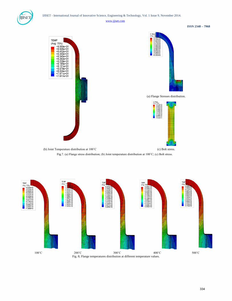
temperatures. From the above results it is found that the optimum flange design is achieved at 30 mm of flange thickness. For different operating temperatures, the flange displacement is found to reduce slightly when the flange thickness increases up to a temperature of 400 C. Moreover, for temperatures higher than 400 C the flange operating pressure and also the material yield stress are reduced resulting in a great reduction in the displacement. The flange optimum thickness is found to be 30 mm which is being suitable for an operating temperature up to 400 C. This result complies with the ASME standards. The joint stress and temperature distributions are shown below in Figure [7], for a flange thickness of 30 mm and an operating temperature of 100 ˚C.
333
IJISET - International Journal of Innovative Science, Engineering & Technology, Vol. 1 Issue 9, November 2014.
www.ijiset.com
ISSN 2348 – 7968
100˚C 200˚C 300˚C 400˚C 500˚C
Fig. 8; Flange temperatures distribution at different temperature values.
(a) Flange Stresses distribution.
(b) Joint Temperature distribution at 100˚C (c) Bolt stress.
Fig.7. (a) Flange stress distribution; (b) Joint temperature distribution at 100˚C; (c) Bolt stress.
334
IJISET - International Journal of Innovative Science, Engineering & Technology, Vol. 1 Issue 9, November 2014.
www.ijiset.com
ISSN 2348 – 7968
The temperature distribution on the flange is shown in Figure [8] for a temperature range from 100 C up to 500 C. The equations for thick cylinder analysis and its temperature distribution are applicable only away from the end caps. These equations are not applicable near the junction on thick walled caps. This is usually treated by experimental approaches or by finite element methods [12].
6. Conclusions
• The flange stress is reduced with the increase of its thickness up to 30 mm, however, the stress is found to increase again for thicknesses higher than 30 mm.
• For the same flange thickness, when the temperature increases the flange stress is reduced.
• For the same temperature, the flange displacement is reduced with the increase of the flange thickness.
• For the same thickness, the flange displacement increases slightly for temperatures up to 200˚C and reduces slightly for temperatures higher than 200 C up to 400˚C. However, for temperatures higher than 400˚C the displacement reduces greatly.
• The bolt stresses are found to reduce with the increase of thickness up to 20 mm. and reduce slightly for thicknesses higher than 20 mm.
• The increase of temperature reduces the bolt stresses because of both the pressure-temperature rating and the joint relaxation due to the joint thermal expansion.
• The flange temperature distribution increases near to the cap and diminishes near to the flange side.
• The temperature distribution shows lower temperature in the inner surface than the internal fluid temperature because of the low thermal resistance on the flange, which shows that the flange acts as a cooling fin on the joint.
• The joint can perform up to 400˚C with a safe operating behavior under different operating conditions of internal pressure and bolt preloading.
References: [1] Nash D.H., Spence J., Tooth A.S., Abid M. and Power D.J.,
“A parametric study of metal-to-metal full face taper-hub flanges,” Int. J. Pressure Vessels and Piping, 77,791–797 (2000).
[2]Abid M. and Nash D.H., “Comparative study of the behaviour of conventional gasketed and compact non-gasketed flanged pipe joints under bolt up and operating conditions,” Int. J. Pressure Vessels and Piping, 80,831–841 (2004).
[3] Abid.M and Nash D.H., “A parametric study of metal-to-metal contact flanges with optimized geometry for safe and no-leak conditions,” Int. J. Pressure Vessels piping, 81, 67–74 (2004).
[4] Abid.M., “Determination of safe operating conditions for gasketed flange joint under combined internal pressure and
temperature: A finite element approach,” Int. J. Pressure Vessels piping, 83, 433–441 (2006).
[5]Couchaux M., Hjiaj M., Ryan I.and Bureau A.,“Effect of contact on the elastic behaviour of bolted connections” NSCC , 288-295 (2009).
[6] Chavan U.S., Dharkunde R. B. and Joshi S.V., “Parametric study of flange joint and weight optimization for safe design and sealability FEA approach” International Journal of Advanced Engineering Technology, Vol.I, Issue III, 266-276 (2010).
[7] Zasiah Tafheem and Khan Mahmud Amanat “Investigation on bolt tension of flanged pipe joint subjected to bending” 4th Annual Paper Meet and 1st Civil Engineering Congress, December 22-24 (2011).
[8]Abdel-Ghany W.E., Ebied, S.J. and Salama M., “Design of Metal-To-Metal Contact Flanges of the Pressure Vessels Using Finite Element Analysis” Int. J.Alazhar university JAEUS, Vol 9, Number 32, 925-935 July (2014).
[9] American Society of Mechanical Engineers, ASME boiler and pressure vessel code. Section II, Part D (2004).
[10]American Society of Mechanical Engineers, ASME pipe flanges and flanged fittings B16.5 (2003).
[11] ABAQUS 12, Abaqus Analysis User's Manual. [12]Ansel C. Ugural, “Mechanical Design an Integrated
Approach” 1st edition (2004).
335