it) - login | accmy.americanchemistry.com/download/presentation/oilfieldbiocides/api... · 30...
TRANSCRIPT

4
wnwwW
4
a
4
n4
4
4
n
11
4
INTRODUCTION TOOIL AND GAS PRODUCTION
(Formerly titled Primer of Oil and Gas Production)
Sponsored by the
EXECUTIVE COMMITTEE ON TRAINING AND DEVELOPMENT
of the
AMERICAN PETROLEUM INSTITUTE
Production Department
Dallas, Texas
OFFICIAL PUBLICATION
It)
Published by
Production Department
AMERICAN PETROLEUM INSTITUTE
211 N. Ervay, Suite 1700
Dallas TX 75201
4

29
CHAPTER 7
SEPARATION , TREATMENT AND STORAGE
M
MM
M
M
M
IN
nAn
Well fluids are often a complex mixture ofliquid hydrocarbons, gas, and some impurities. Itis necessary to remove the gas and some impuritiesfrom the liquid hydrocarbons before they arestored. transported. and sold. Liquid hydrocarbonsand objectionable impurities must also be removedfrom natural gas before the gas goes to a salesline. Impurities that might be found in some wellstreams are hydrogen sulfide, carbon dioxide, freewater. water vapor, mercaptans. nitrogen, helium.and solids. Nearly all of the impurities cause var-ious types of operating problems.
The separation of natural gas. liquid hydrocar-bons, and impurities is accomplished by variousfield-processing methods, depending upon the com-position of' the well stream and the desired endproduct. These methods include time, chemicals.gravity, heat, mechanical or electrical processes,and combinations of these.
Separators
Separation of well-stream gas from free liquidsis the most common and simplest form of fieldprocessing. The equipment most widely used forthis type of processing is referred to as a separa-tor. The separation of natural gas from liquidsand or impurities in a separator combines gravity.time. mechanical processes, and occasionallychemicals.
The size of the separator is dependent upon rateof flow of the natural gas and; or liquids going inthe vessel. The operating pressure of the vessel isdependent upon the pressure of the gas sales line,the flowing pressure of the well, and the operatingpressure desired by the lease operator.
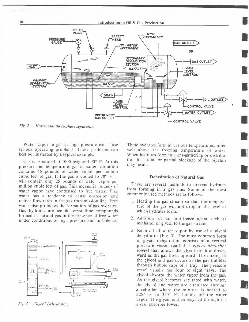
Separators are built in various designs, such asvertical, horizontal and spherical. The internals ofthe vessel, to aid in the mechanical separation ofthe gas and liquids, are of a special design.depending upon the manufacturer. Although mostseparators are tnvo-phase in design (Fig. 1). sepa-rating the gas and liquids, they can be built three-phase to separate natural gas, liquid hydrocarbons,and free water (Fig. 2).
Under certain conditions it is desirable to usemore than one stage of separation to obtain morerecovery of fluids.
Although natural gas leaving the separator nolonger contains free liquids, the gas may be satu-rated with water vapors (See "Dehydration ofNatural Gas"). Liquid hydrocarbons leaving theseparator do not contain free gas; however, theymay contain water, basic sediment, and otherimpurities (See "Oil Treating").
Natural gas contains substantial amounts ofwater vapor when produced from a gas well orseparated from liquid hydrocarbons. When gasand oil are separated at low pressure (below 100psig), the gas is normally gathered in a low pres-sure gathering system. The gas goes to a gas plantwhere the gas is compressed and additional liquidhydrocarbons, water, and other impurities areremoved. In the high pressure separation of oiland gas (above 100 psig), the gas may be meteredand sold to the pipeline company in the field orsent to a gas plant for further processing. The gasis then sold to a gas transmission company.
P
DRAIN
SECONDARYV
SN
SECTON
Fig. I - Vertical two-phase separator.
GAS OUTSET
30 Introduction to Oil & Gas Production I
PRESSUREGAUGE -
nINLET
PR/MARYS£PARAr/OSECT/ON
Fig. 2 - Horizontal three-phase separator.
OIL OUTLET
L- CONTROL VALVE
WATER OUTLET
rI
It
nr
Water vapor in gas at high pressure can causeserious operating problems. These problems canbest be illustrated by a typical example:
Gas is separated at 1000 psig and 90° F. At thispressure and temperature, gas at water saturationcontains 46 pounds of water vapor per millioncubic feet of gas. If the gas is cooled to 70° F. itwill contain only 25 pounds of water vapor permillion cubic feet of gas. This means 21 pounds ofwater vapor have condensed to free water. Freewater has a tendency to cause corrosion andreduce flow rates in the gas transmission line. Freewater also promotes the formation of gas hydrates.Gas hydrates are ice-like crystalline compoundsformed in natural gas in the presence of free waterunder conditions of high pressure and turbulence.
Fig. 3 - Glycol Dehydrator.
cErroE AEaG^^E^SERGE
These hydrates form at various temperatures. oftenwell above the freezing temperature of water.When hydrates form in a gas-gathering or distribu-tion line. total or partial blockage of the pipelinemay result.
Dehydration of Natural Gas
There are several methods to prevent hydratesfrom forming in a gas line. Some of the mostcommonly used methods are as follows:
1. Heating the gas stream so that the tempera-ture of the gas will not drop to the level atwhich hydrates form.
2. Addition of an anti-freeze agent such asmethanol or glycol to the gas stream.
3. Removal of water vapor by use of a glycoldehydrator (Fig. 3). The most common formof glycol dehydration consists of a verticalpressure vessel (called a glycol absorbertower) that allows the glycol to flow down-ward as the gas flows upward. The mixing ofthe glycol and gas occurs as the gas bubblesthrough bubble caps of a tray. The pressurevessel usually has four to eight trays. Theglycol absorbs the water vapor from the gas.As the glycol becomes saturated with water.the glycol and water are circulated througha reboiler where the mixture is heated to325° F. to 350° F., boiling off the watervapor. The glycol is then recycled through theglycol absorber tower.
I
ri
rr
11
I

s
nn
Separation. Treatment and Storage 31
4. Dehydration using solid desiccants (drying
agents) such as alumina, silica-gel, silicon-
alumina beads. and molecular-sieve. Gas flows
through the desiccant bed where water is
adsorbed. On a time cycle basis, the gas
stream is switched through another bed and
the first bed is heated to remove the water.
For continuous operation there must be at
least two beds.
I5. Dehydration by expansion refrigeration.
which can be accomplished if there is a suf-
ficient pressure drop between well-flowing
pressure and separator pressure. This is ac-complished by use of heat exchangers andexpansion of the gas.
Most dehydrated gas that goes to the sales line
contains no more than seven pounds of water
vapor per million cubic feet of gas.
Objectionable amounts of other impurities in the
I natural gas stream such as hydrogen sulfide and
carbon dioxide are removed by various processes.The methods may be broadly categorized as those
I depending on chemical reaction, physical solution,
and absorption.
Gas transmission companies set specifications on
U how free of impurities the gas must he before it is
purchased.
A Oil Treating
When crude oil is produced. various amounts of
as water and other impurities are mixed withg
U,,
the oil. Some of this mixture comes as free oil.
some as free water. and some as a homogeneousmixture known as an emulsion. The gas, water
U and other impurities (known as basic sediment andwater) must be removed before selling the oil. Thisseparation process is called oil treating.
Treating systems are important parts of lease
equipment. Experience in a particular field or area
is valuable in determining the best equipment for
the application.
In selecting a treating system, a number of fac-
tors should be considered to determine the most
U desirable method of treating the crude oil to pipe-line requirements. Some of these factors are:
1. Tightness of emulsion.
2. Specific gravity of the oil and produced
water.
3. Corrosiveness of the oil. gas. and produced
water.
4. Scaling tendencies of the produced water.
5. Quantity of fluid to be treated and percent of
water in the fluid.
6. Availability of sales line for the gas.
7. Desirable operating pressure for the equip-
ment.
8. Paraffin-forming tendencies of the crude oil.
Oil-field emulsions are usually of the water-in-
oil type; however, a few of the emulsions are oil-
in-water type and are called reverse emulsions.
Emulsions are complex and each should be consid-
ered individually.
In order to break a crude oil emulsion and
obtain clean oil, it is necessary to displace the
emulsifier and its film. This brings about the coa-
lescence of droplets of water and furnishes a
means and time period of undisturbed settling of
the coalesced water drops. There are several
methods used in conjunction with one another to
"treat" an oil emulsion.
Heater-Treaters
Treaters equipped with electrodes are normally
horizontal in design. They are referred to as Elec-
trostatic Coalescers or Chem-electric treaters
(Fig. 5). In some applications these treaters are the
most desirable because they will treat at a lower
temperature than a conventional heater-treater,
saving fuel and oil gravity.
A heater-treater (Fig. 4) is normally used in
"treating" oil emulsions. The heater-treater uses
thermal. gravity, mechanical. and sometimes chem-
ical and r or electrical methods to break emulsions.
Free Water Knockouts ( FWKOs)
When there is sufficient free water production
on a lease, a FWKO (Fig. 6) is often installed to
separate free gas and free water from free oil and
emulsion. This vessel can be either horizontal or
vertical in design. The size is dependent upon the
desired retention time and the volume of water per
day to be handled.
The methods used to facilitate separation when
FWKOs are used are time, gravity, mechanical.
and sometimes chemical.
Heater-treaters can be vertical or horizontal in
design. The size is dependent upon the volume of
oil and water to be handled.
4

32 Introduction to Oil & Gas Production
When heat must be used to break an emulsion,much fuel gas can be saved by using the FWKO.Heating unnecessary water is not only useless, butit takes more than twice as many BTUs to heatwater to a given temperature as it does to heat oil.This can be very costly.
Gun Barrel
settle toward the bottom of a tank and oil will riseto the top due to the water's having a higher spe-cific gravity than the oil. Heat and chemicals maybe used to shorten the time required for settlingand to improve the separation of the two liquids.The settling vessel is known as a gun barrel orwash tank (Fig. 7).
The gun barrel comes in various designs, how-ever. it usually has sufficient height to allow theclean oil to gravity flow into the stock t k Than s. eIn some cases an oil-water emulsion is not very water is drawn off through the water leg, whichstable and, if sufficient time is allowed, water will also regulates the oil-water interface level.
Stack Head
Stack
Stack Brace
Gas Equalizing Line
Outside Siphon
Condensing Head
Centrifugal Gas Scrubber
a
I
I
t
a
a
I
a
nThermostat Connection
Thermometer-_n
f-1,Stack breeching .__6^-r.
I
I
nGas Valve
Field Piping nn11
Gas Scrubber Drip
Trap
Fig. 4 - Flow diagram.for a vertical heater-treater. n

4
n4
w4
14
nnnA
wA
WATER ,AS
Fig. 5 - Electrostatic coalescer.
INLET
WATFF
Separation. Treatment and Storage
AWOAIL EMULSION
OUTSIDE SHRLLOI
GAS
OILS.R000
JfRATER
OIL NTLME TC SF4E")E3t
GAS L
ACCESS MANWA
4
Fig. 6 - Free water knockout (with oil split option).
AS OUTLE-OIL SPLITTER ORiEN. SHO`NN
33
It

34
q GAS
0 EMULSION
OIL
WATER
"JUG"HEATER(OPTIONAL)
GAS EQUALIZER
Fig. 7- Schematicflow diagram ofgun barrel (wash tank) installation.
Storage Tanks
Oil that is free of impurities to the extent that it
will meet pipeline specifications is referred to as
clean oil or pipeline oil. It is oil from a separator,
free water knockout, heater-treater, or gun barrel,
depending upon the type of treating necessary to
obtain the clean oil. The pipeline oil goes from the
treating facilities to the storage tanks, known as
stock tanks.
The number and size of stock tanks depend
upon the volume of oil produced each day.
method of selling the oil to the pipeline, and howfrequently and at what rate oil is taken by the
pipeline company.
Introduction to Oil & Gas Production
The separation, treating, and storage facilities
are commonly referred to as a tank battery
(Fig. 8).
The two basic types of stock tanks are bolted
steel and welded steel. Bolted steel stock tanks are
normally 500 barrels or larger and are assembled
on location. Welded steel stock tanks range in size
from 90 barrels to several thousand barrels.
Welded tanks up to 400 barrels in capacity (and in
some cases 500 barrels) are shop-welded and are
transported as a complete unit to the tank battery
site. Larger tanks are welded on location. Welded
tanks can be internally coated to protect them
from corrosion. Bolted tanks offer the option of
internal lining or galvanized construction for pro-
tection against corrosion.

n
an4
A
M
uwnnnn
Separation. Treatment and Storage
Vapor Recovery System
When oil is treated under pressure and thengoes to a stock tank at near atmospheric pressure.some liquid hydrocarbons flash to gas. Some fac-tors that determine the volume of flash gas are:
I. Type of liquid hydrocarbons.
2. Treating pressure.
3. Treating temperature.
4. Volume of liquid hydrocarbons.
5. Temperature of liquid hydrocarbons enteringtank.
6. Diameter of tank.
7. How liquids enter the tank.
8. How long liquid hydrocarbons stay in tankbefore going to pipeline.
For many years the flash gas or vapors were
vented to the atmosphere. It is no longer a ques-
NET OILCOMPUTER
NET OILCOMPUTER
Fig. 8 - General lease service installation.
35
tion of economics to justify vapor recovery sincegovernment agencies are insisting on vapor rc-coverv to reduce air pollution. Many improve-ments in production practices and equipmentdesign in the past few years have made recovery oflow-pressure hydrocarbon vapors practical. botheconomically and ecologically.
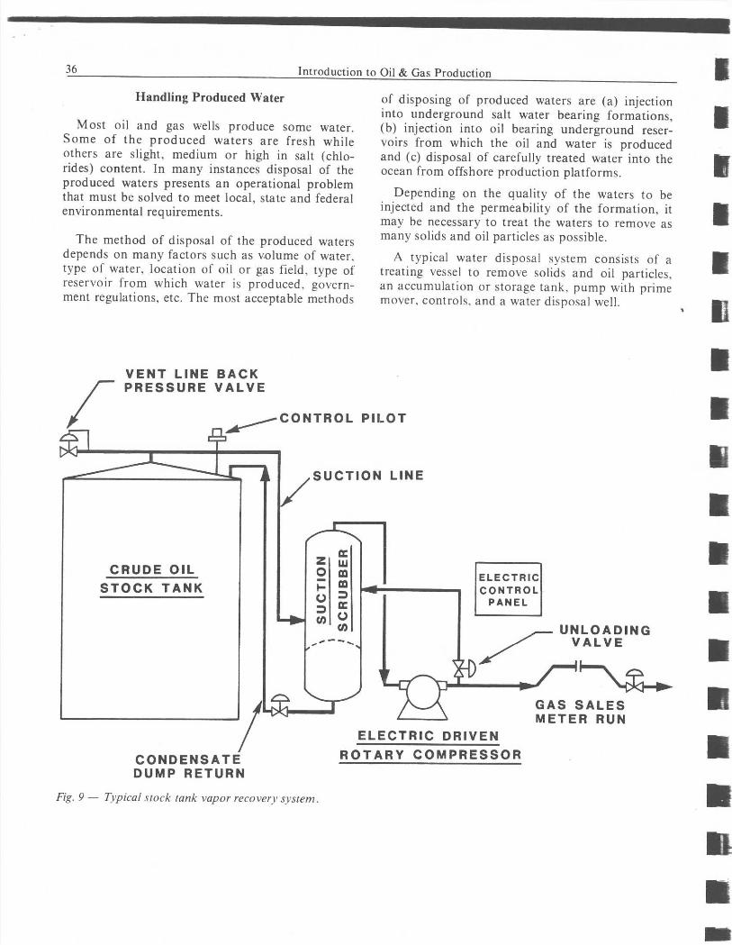
A vapor recovery unit (Fig. 9) consists of a con-
trol pilot mounted on a tank for control of com-pressors, a scrubber to keep liquid hydrocarbons
out of the compressor. a compressor. and controlpanel. The electric motor-driven compressor will
start by a signal from the control pilot at approx-imately one ounce of gas pressure. It will shut off
at approximately 1/4 ounce gas pressure. It isnecessary to keep a positive pressure in the tank to
keep out air and prevent evaporation of the crude
oil. Air contamination of the gas can create explo-sive mixtures and accelerate corrosion of equip-ment. Stock tanks are normally designed to holdliquid hydrocarbons with a maximum of fourounces of positive gas pressure.
n
36
Handling Produced Water
Introduction to Oil & Gas Production
Most oil and gas wells produce some water.Some of the produced waters are fresh whileothers are slight, medium or high in salt (chlo-rides) content. In many instances disposal of theproduced waters presents an operational problemthat must be solved to meet local, state and federalenvironmental requirements.
The method of disposal of the produced watersdepends on many factors such as volume of water,type of water, location of oil or gas field, type ofreservoir from which water is produced. govern-ment regulations, etc. The most acceptable methods
VENT LINE BACKPRESSURE VALVE
SUCTION LINE
CRUDE OIL 0w
ELECTRICSTOCK TANK I- TR LCON O
U PANEL
L4004 N C.)
UNLOADINGVALVE
0
GAS SALESMETER RUN
CONDENSATEDUMP RETURN
of disposing of produced waters are (a) injectioninto underground salt water bearing formations,(b) injection into oil bearing underground reser-voirs from which the oil and water is producedand (c) disposal of carefully treated water into theocean from offshore production platforms.
Depending on the quality of the waters to beinjected and the permeability of the formation, itmay be necessary to treat the waters to remove asmany solids and oil particles as possible.
A typical water disposal system consists of atreating vessel to remove solids and oil particles,an accumulation or storage tank, pump with primemover, controls, and a water disposal well.
CONTROL PILOT
ELECTRIC DRIVEN
ROTARY COMPRESSOR
Fig. 9 - Typical stock tank vapor recovery svstenm.

WN
n rz
7 L^̂uu OZ - a 3 r
< N H
= t j a m m yz
n OwO ¢ W J Z a as ¢j
U F ¢W QW ON ¢ JWN NNWOaW ^-«W
Z 0 Y u^ 0¢ ¢¢ <O0<0
WJ V O O
U W U F h O O W< << Z ^J12<Z
^ V Q
O N O Y W O
QO 0o UGH^.
{{¢uY^.
<IG WN
J 2 O JO O Q<¢JFt^ J ¢ W W< «
O a F n J N U O O 0 ii < N 4 W 0 0 0 Lw a
<
00000000 O®®®®®®®®®®