itu-t rec. g.971 (10/2020) general features of optical
TRANSCRIPT

I n t e r n a t i o n a l T e l e c o m m u n i c a t i o n U n i o n
ITU-T G.971 TELECOMMUNICATION STANDARDIZATION SECTOR OF ITU
(10/2020)
SERIES G: TRANSMISSION SYSTEMS AND MEDIA, DIGITAL SYSTEMS AND NETWORKS
Digital sections and digital line system – Optical fibre submarine cable systems
General features of optical fibre submarine cable systems
Recommendation ITU-T G.971

ITU-T G-SERIES RECOMMENDATIONS
TRANSMISSION SYSTEMS AND MEDIA, DIGITAL SYSTEMS AND NETWORKS
INTERNATIONAL TELEPHONE CONNECTIONS AND CIRCUITS G.100–G.199
GENERAL CHARACTERISTICS COMMON TO ALL ANALOGUE CARRIER-TRANSMISSION SYSTEMS
G.200–G.299
INDIVIDUAL CHARACTERISTICS OF INTERNATIONAL CARRIER TELEPHONE SYSTEMS ON METALLIC LINES
G.300–G.399
GENERAL CHARACTERISTICS OF INTERNATIONAL CARRIER TELEPHONE SYSTEMS ON RADIO-RELAY OR SATELLITE LINKS AND INTERCONNECTION WITH METALLIC LINES
G.400–G.449
COORDINATION OF RADIOTELEPHONY AND LINE TELEPHONY G.450–G.499
TRANSMISSION MEDIA AND OPTICAL SYSTEMS CHARACTERISTICS G.600–G.699
DIGITAL TERMINAL EQUIPMENTS G.700–G.799
DIGITAL NETWORKS G.800–G.899
DIGITAL SECTIONS AND DIGITAL LINE SYSTEM G.900–G.999
General G.900–G.909
Parameters for optical fibre cable systems G.910–G.919
Digital sections at hierarchical bit rates based on a bit rate of 2048 kbit/s G.920–G.929
Digital line transmission systems on cable at non-hierarchical bit rates G.930–G.939
Digital line systems provided by FDM transmission bearers G.940–G.949
Digital line systems G.950–G.959
Digital section and digital transmission systems for customer access to ISDN G.960–G.969
Optical fibre submarine cable systems G.970–G.979
Optical line systems for local and access networks G.980–G.989
Metallic access networks G.990–G.999
MULTIMEDIA QUALITY OF SERVICE AND PERFORMANCE – GENERIC AND USER-RELATED ASPECTS
G.1000–G.1999
TRANSMISSION MEDIA CHARACTERISTICS G.6000–G.6999
DATA OVER TRANSPORT – GENERIC ASPECTS G.7000–G.7999
PACKET OVER TRANSPORT ASPECTS G.8000–G.8999
ACCESS NETWORKS G.9000–G.9999
For further details, please refer to the list of ITU-T Recommendations.

Rec. ITU-T G.971 (10/2020) i
Recommendation ITU-T G.971
General features of optical fibre submarine cable systems
Summary
Recommendation ITU-T G.971 applies to optical fibre submarine cable systems. The purpose of this
Recommendation is to identify the main features of optical fibre submarine cable systems, and to
provide generic information on relevant Recommendations in the field of optical fibre submarine cable
systems. A common implementation relevant to all the optical fibre submarine cable systems is
described in Annex A. Specific information relevant to each optical fibre submarine cable system is
included in annexes of other Recommendations. The updated data on cable ships and submersible
equipment of various countries are also described in Appendix I.
In this latest version, the diagram of interoperable optical fibre submarine cable systems and
boundaries are described in Figure 1(b).
History
Edition Recommendation Approval Study Group Unique ID*
1.0 ITU-T G.971 1993-03-12 XV 11.1002/1000/1036
2.0 ITU-T G.971 1996-11-11 15 11.1002/1000/3830
3.0 ITU-T G.971 2000-04-04 15 11.1002/1000/5059
4.0 ITU-T G.971 2004-06-13 15 11.1002/1000/7339
5.0 ITU-T G.971 2007-07-29 15 11.1002/1000/9157
6.0 ITU-T G.971 2010-07-29 15 11.1002/1000/10882
7.0 ITU-T G.971 2016-11-13 15 11.1002/1000/13088
8.0 ITU-T G.971 2020-10-29 15 11.1002/1000/14501
Keywords
Cable ship, optical fibre submarine cable systems, submersible equipment.
* To access the Recommendation, type the URL http://handle.itu.int/ in the address field of your web
browser, followed by the Recommendation's unique ID. For example, http://handle.itu.int/11.1002/1000/11
830-en.

ii Rec. ITU-T G.971 (10/2020)
FOREWORD
The International Telecommunication Union (ITU) is the United Nations specialized agency in the field of
telecommunications, information and communication technologies (ICTs). The ITU Telecommunication
Standardization Sector (ITU-T) is a permanent organ of ITU. ITU-T is responsible for studying technical,
operating and tariff questions and issuing Recommendations on them with a view to standardizing
telecommunications on a worldwide basis.
The World Telecommunication Standardization Assembly (WTSA), which meets every four years, establishes
the topics for study by the ITU-T study groups which, in turn, produce Recommendations on these topics.
The approval of ITU-T Recommendations is covered by the procedure laid down in WTSA Resolution 1.
In some areas of information technology which fall within ITU-T's purview, the necessary standards are
prepared on a collaborative basis with ISO and IEC.
NOTE
In this Recommendation, the expression "Administration" is used for conciseness to indicate both a
telecommunication administration and a recognized operating agency.
Compliance with this Recommendation is voluntary. However, the Recommendation may contain certain
mandatory provisions (to ensure, e.g., interoperability or applicability) and compliance with the
Recommendation is achieved when all of these mandatory provisions are met. The words "shall" or some other
obligatory language such as "must" and the negative equivalents are used to express requirements. The use of
such words does not suggest that compliance with the Recommendation is required of any party.
INTELLECTUAL PROPERTY RIGHTS
ITU draws attention to the possibility that the practice or implementation of this Recommendation may involve
the use of a claimed Intellectual Property Right. ITU takes no position concerning the evidence, validity or
applicability of claimed Intellectual Property Rights, whether asserted by ITU members or others outside of
the Recommendation development process.
As of the date of approval of this Recommendation, ITU had not received notice of intellectual property,
protected by patents, which may be required to implement this Recommendation. However, implementers are
cautioned that this may not represent the latest information and are therefore strongly urged to consult the TSB
patent database at http://www.itu.int/ITU-T/ipr/.
© ITU 2021
All rights reserved. No part of this publication may be reproduced, by any means whatsoever, without the prior
written permission of ITU.

Rec. ITU-T G.971 (10/2020) iii
Table of Contents
Page
1 Scope ............................................................................................................................ 1
2 References..................................................................................................................... 1
3 Definitions .................................................................................................................... 2
3.1 Terms defined elsewhere ................................................................................ 2
4 Abbreviations and acronyms ........................................................................................ 2
5 Conventions .................................................................................................................. 2
6 Features of optical fibre submarine cable systems ....................................................... 2
7 Relationship among Recommendations relevant to optical fibre submarine cable
systems .......................................................................................................................... 5
Annex A – Common implementation aspects of optical submarine cable systems for
manufacturing, installing and maintenance .................................................................. 6
A.1 Introduction .................................................................................................... 6
A.2 Manufacturing ................................................................................................ 6
A.3 System installation .......................................................................................... 7
A.4 System commissioning ................................................................................... 8
A.5 Maintenance ................................................................................................... 8
Appendix I – Data on cable ships and submersible equipments of various countries ............. 10
I.1 Cable ships ...................................................................................................... 10
I.2 Submersible equipment .................................................................................. 17
Bibliography............................................................................................................................. 24


Rec. ITU-T G.971 (10/2020) 1
Recommendation ITU-T G.971
General features of optical fibre submarine cable systems
1 Scope
This Recommendation applies to optical fibre submarine cable systems.
The purpose of this Recommendation is to identify the main features of optical fibre submarine cable
systems, and to provide generic information on relevant Recommendations in the field of optical fibre
submarine cable systems. Annex A contains common implementation aspects of all optical submarine
cable systems. Appendix I contains data on cable ships and submersible equipment of various
countries.
2 References
The following ITU-T Recommendations and other references contain provisions which, through
reference in this text, constitute provisions of this Recommendation. At the time of publication, the
editions indicated were valid. All Recommendations and other references are subject to revision;
users of this Recommendation are therefore encouraged to investigate the possibility of applying the
most recent edition of the Recommendations and other references listed below. A list of the currently
valid ITU-T Recommendations is regularly published. The reference to a document within this
Recommendation does not give it, as a standalone document, the status of a Recommendation.
[ITU-T G.821] Recommendation ITU-T G.821 (2002), Error performance of an international
digital connection operating at a bit rate below the primary rate and forming
part of an Integrated Services Digital Network.
[ITU-T G.826] Recommendation ITU-T G.826 (2002), End-to-end error performance
parameters and objectives for international, constant bit-rate digital paths and
connections.
[ITU-T G.828] Recommendation ITU-T G.828 (2000), Error performance parameters and
objectives for international, constant bit-rate synchronous digital paths,
including Cor.1 (2001).
[ITU-T G.8201] Recommendation ITU-T G.8201 (2011), Error performance parameters and
objectives for multi-operator international paths within optical transport
networks, including Cor.1 (2015).
[ITU-T G.972] Recommendation ITU-T G.972 (2020), Definition of terms relevant to optical
fibre submarine cable systems.
[ITU-T G.973] Recommendation ITU-T G.973 (2016), Characteristics of repeaterless optical
fibre submarine cable systems.
[ITU-T G.973.1] Recommendation ITU-T G.973.1 (2009), Longitudinally compatible DWDM
applications for repeaterless optical fibre submarine cable systems.
[ITU-T G.973.2] Recommendation ITU-T G.973.2 (2011), Multichannel DWDM applications
with single channel optical interfaces for repeaterless optical fibre submarine
cable systems.
[ITU-T G.974] Recommendation ITU-T G.974 (2007), Characteristics of regenerative optical
fibre submarine cable systems.
[ITU-T G.977] Recommendation ITU-T G.977 (2015), Characteristics of optically amplified
optical fibre submarine cable systems.

2 Rec. ITU-T G.971 (10/2020)
[ITU-T G.977.1] Recommendation ITU-T G.977.1 (2020), Transverse compatible DWDM
applications for repeatered optical fibre submarine cable systems.
3 Definitions
3.1 Terms defined elsewhere
This Recommendation uses the terms defined in [ITU-T G.972].
4 Abbreviations and acronyms
This Recommendation uses the following abbreviations and acronyms:
BAS Burial Assessment Survey
BOL Beginning of Life
BU Branching Unit
CPT Cone Penetrometer Testing
CTE Cable Terminating Equipment
DP-system Dynamic Positioning-system
DWDM Dense Wavelength Division Multiplexing
ECR Electrical Command Response
ME Monitoring Equipment
MC Maintenance Controller
OCJ Optical Coupling Junction
PFE Power Feeding Equipment
PLGR Pre-Lay Grapnel Run
ROV Remotely Operated Vehicle
SCARAB Submersible Craft Assisting Repair and Burial
SWL Safe Working Load
TSE Terminal Station Equipment
TTE Terminal Transmission Equipment
5 Conventions
None.
6 Features of optical fibre submarine cable systems
An optical fibre submarine cable system has specific technical features:
a) A submarine cable system should have a long lifetime and be highly reliable. The main reason
for this that the construction and maintenance of a link is long and expensive because of the
difficulty in accessing a submerged plant. Moreover, most submarine links are of strategic
importance in the transmission network – the interruption of a link usually results in
significant loss of traffic and revenue.
b) A submarine cable system should possess mechanical characteristics which enable it:
Rec. ITU-T G.971 (10/2020) 3
1) to be installed accurately with correct slack and with due attention to safety
considerations on the seabed – deep water installations can reach up to 8 000 metres. (In
general, submarine cable systems shall be installed, buried or inspected by specially
designed cable ships and submerged equipment. Detailed information of such cable ships
and submerged equipment (i.e., ploughs, ROVs, etc.) is contained in Appendix I);
2) to resist environmental conditions on the sea bottom at the installation depth, particularly
hydrostatic pressure, temperatures, abrasion, corrosion and marine life;
3) to be adequately protected (i.e., by armouring or burying) against aggression, due for
example to trawlers or anchors;
4) to survive recovery from such a depth, and subsequent repair and relay, with due safety
considerations.
c) The material characteristics of a submarine cable system should enable the optical fibre:
1) to achieve its desired reliability over its design lifetime;
2) to tolerate stated loss and aging mechanisms, especially bending, strain, hydrogen, stress,
corrosion and radiation.
d) The transmission quality of a submarine cable system should follow, as a minimum
[ITU-T G.821] or [ITU-T G.826] or [ITU-T G.828] or [ITU-T G.8201].
Figure 1(a) shows the basic concept of optical fibre submarine cable systems and boundaries. Optical
submarine repeaters or optical submarine branching units could be included, depending on each
system requirement. Figure 1(b) shows the diagram of interoperable optical fibre submarine cable
systems and boundaries.
In Figure 1, "A" denotes the system interfaces at the terminal station (where the system can be
interfaced to terrestrial digital links or to other submarine cable systems), "B" denotes beach joints or
landing points, and "C" denotes interoperable cable portion interface. Numbers in brackets in the
figure refer to [ITU-T G.972].

4 Rec. ITU-T G.971 (10/2020)
Figure 1 – Examples of (a) optical fibre submarine cable systems, (b) interoperable optical
fibre submarine cable systems
NOTE – Figure 1(b) illustrates an example of the optical fibre submarine cable system with terrestrial network.
The land repeaters in the land portion may or may not be a part of the interoperable cable portions.

Rec. ITU-T G.971 (10/2020) 5
7 Relationship among Recommendations relevant to optical fibre submarine cable
systems
Relationships among the various Recommendations pertaining to optical fibre submarine cable
systems are shown in the flow chart presented in Figure 2. Recommendations relevant to optical fibre
submarine cable systems can be categorized into three groups. The first group covers general aspects
on optical fibre submarine cable systems. This category is composed of [ITU-T G.971],
[ITU-T G.972] and [b-ITU-T G.Sup.41]. These documents respectively describe general features,
definitions and design guidelines for optical fibre submarine systems. The second group deals with
the components or functions used in optical fibre submarine systems. This category is composed of
[b-ITU-T G.975], [b-ITU-T G.975.1], [b-ITU-T G.976], [b-ITU-T G.978] and [b-ITU-T G.979].
These documents describe forward error correction, advanced forward error correction, test methods,
optical fibre cables and characteristics of monitoring systems relevant to optical fibre submarine
systems. The final group describes system requirements. This category contains [ITU-T G.973],
[ITU-T G.973.1], [ITU-T G.973.2], [ITU-T G.974], [ITU-T G.977] and [ITU-T G.977.1].
Respectively, these Recommendations consider: the repeaterless, longitudinal compatible
repeaterless, single channel interface based repeaterless, regenerative and optically amplified, and
transverse compatible DWDM repeatered submarine systems.
Figure 2 – Relationships among Recommendations relevant to
optical fibre submarine cable systems

6 Rec. ITU-T G.971 (10/2020)
Annex A
Common implementation aspects of optical submarine cable systems for
manufacturing, installing and maintenance
(This annex forms an integral part of this Recommendation.)
A.1 Introduction
This annex outlines the common aspects of submarine cable systems specified in [ITU-T G.973],
[ITU-T G.973.1], [ITU-T G.973.2], [ITU-T G.974], [ITU-T G.977] and [ITU-T G.977.1], such as
manufacturing, installation and maintenance.
The information provided in this annex is intended as a guide to current practice and is not intended
as a Recommendation relating to existing or future systems.
A.2 Manufacturing
A.2.1 Quality in optical fibre submarine cable systems
The high performance and reliability requirement established for an optical fibre submarine cable
system can be fulfilled only if stringent quality procedures are applied during designing,
manufacturing and laying of a system. Although quality procedures are particular to each optical fibre
submarine cable supplier, the following basic principles generally apply.
A.2.1.1 Qualification of the designs and technologies
This activity – part of the development process – is intended to demonstrate that the performance of
technology, a component or an assembly is compatible with meeting the overall system performance
requirements and provides reasonable assurance that the reliability target can be met. Qualification
includes high-stress testing, intended to estimate the durability of the technology, component or
subassembly and to determine the screening procedure. It also includes long-term life testing (some
of which might be accelerated, for instance by the temperature), the purpose of which is to confirm
the validity of the screening procedure and to evaluate the lifetime and/or the reliability of the
technology, component or assembly. Qualification of a cable or submarine equipment may also
include sea trials.
A.2.1.2 Certification of components and sub-assemblies
This activity, part of the manufacturing process, is intended to assure the ability of each component
or assembly to comply with its performance and reliability specifications, once installed. For
submarine equipment, each component is individually certified. The certification is based on the
results of screening tests. Its aim is to remove any items or components that may be unsatisfactory,
particularly those likely to exhibit early failures.
A.2.1.3 Manufacturing inspection
This activity, during the manufacturing process, is intended to verify that the quality plan is respected,
that each operation is accomplished according to the agreed procedure, and that the result is
satisfactory.
The responsibility for manufacturing inspection can be shared between the manufacturer and the
purchaser of an optical fibre submarine cable system.
A.2.1.4 Factory acceptance tests
After completion of the manufacture of each item (TSE and submerged equipment), functional and
performance tests must be carried out in order to release the equipment from the factory.
Rec. ITU-T G.971 (10/2020) 7
This activity, conducted in the factory, should comprise all tests necessary to confirm that TSE
(including final software) and submerged equipment (repeater and cable sections) are ready for
installation or assembly. The tests should demonstrate that the requirements of the technical
specification will be met by the segments and the full network once installed or assembled, if no
discrepancy occurs during the installation or assembly period.
On completion of factory testing, equipment may be tested during a trial period to check its stability.
A.2.2 Assembly and loading procedure
Link assembly consists of jointing the cable sections, the repeaters and the branching units and
checking that the guaranteed margin is present for each fibre in each cable section, so as to constitute
the submarine portion. Link assembly is usually performed in the cable factory prior to loading.
Ship loading consists of installing the submarine portion, or fractions of it, on board the cable ship,
prior to laying. Ship loading is generally performed with the link unpowered. Tests are made
periodically during loading to confirm that the performance of the assembled equipment has not been
affected by the loading process.
A.3 System installation
A.3.1 Submarine route survey
A route survey is performed prior to cable laying so as to select the cable route and means of cable
protection (lightweight protection, armour, burial). The route survey consists of studying the sea
depth profile, the sea bottom temperature and seasonal variations, the morphology and nature of the
sea bottom, the position of existing cables and pipes, the cable fault history, fishing and mining
activities, sea current, seismic activity, laws, etc.
A cable route study should normally be carried out prior to the start of a route survey to determine all
environmental, political, economical and practical aspects related to the route. Discussions should be
held with local authorities and fishing bodies for this purpose, together with the inspection of landing
sites and access points, as necessary.
An assessment of burial feasibility can also be carried out as part of the route survey, either through
direct continuous measurement (burial assessment survey (BAS)) or discrete periodic measurement
(cone penetrometer testing (CPT)).
A.3.2 Submarine cable installation
Cable laying is normally performed using a recognized cable-ship after any necessary route clearance
in shallow water has been carried out (e.g., pre-lay grapnel run (PLGR)).
Laying is normally undertaken only when weather and sea conditions do not create severe risk of
damage to the submarine portion, cable ship and laying equipment, or of injury to personnel.
The cable may be buried in the seabed to increase cable protection. Burial can be undertaken during
laying by using a sea plough towed by the laying cable ship, or after laying using a self-propelled
submersible robot or other means.
During laying, a predetermined cable overlength (slack) is laid, so as to ensure that the cable is
properly laid on the sea bottom. The system should be tested during the laying and at the end of
laying, to ensure that no significant system degradation has been induced. Laying testing includes
transmission and functional tests, and may include tests on redundant subassemblies. To permit
testing during cable laying, the link may be powered, provided that safety regulations are respected.
A.3.3 Land cable installation and testing
Land cable tests will be performed after the completion of land cable installation at each site to
confirm performances.

8 Rec. ITU-T G.971 (10/2020)
In particular, the return earth system shall be tested after its installation.
A.3.4 Terminal station equipment installation and testing
After completion of terminal station equipment installation activities in the cable terminal station, a
site acceptance testing programme should be conducted, based on the factory acceptance test
programme already performed. Results of both periods should be compared. In the event of an
unfavourable comparison between the two sets of results, the cause of the irregularities should be
determined.
All equipment units provided as spares shall be tested for correct operation by substitution with
working units.
On completion of the suite tests, the equipment shall be subject to a continuous confidence trial period
to be defined depending on the equipment type.
Following the site acceptance testing period for each item, interconnection of equipment should be
carried out to control their interoperability. A specific integration test plan should then be conducted.
The results obtained could be compared with previous results (including technology demonstration).
In the event of an unfavourable comparison between the two sets of results, the cause of the
irregularities should be determined.
A.4 System commissioning
Commissioning testing is performed prior to installing traffic on the system to ensure that the system
meets its overall transmission performance contractual requirement, and that all functionalities, with
respect to the network management, are operating. When extra margins are available at the beginning
of life (BOL), it is recommended that they be assessed in order to track the ageing of the system.
If redundancy is used in the design to meet the reliability performance, redundant components could
be used to correct faults occurring during laying or prior to commissioning. However, the aim is to
ensure that the number of redundant devices remaining is sufficient to meet, with a high probability,
the target for the number of ship repairs.
On completion of the system commissioning period, a continuous transmission segment out-of-
service confidence trial should be followed. Carefully controlled procedures should be established to
prevent the introduction of errors through human action. Any irregularity, variation alarm or non-
routine event observed should be investigated.
A.5 Maintenance
A.5.1 Routine maintenance
Routine maintenance is performed from the terminal stations using the supervisory system. It consists
of periodic monitoring of the system parameters and, when required, preventive redundancy
switching.
A.5.2 Maintenance at sea
Optical fibre submarine cable systems can be subject to faults, due in particular to external aggression
and component failure. It is important to define and develop well-established and efficient repair
procedures and equipment in order to facilitate repair and limit loss of traffic.
Maintenance at sea is usually performed using dedicated repair cable ships.
A.5.2.1 Fault localization
For systems equipped with optical submarine repeaters, a first localization to within one supervisory
section is obtained using the supervisory system.
Rec. ITU-T G.971 (10/2020) 9
For the end cable sections, cable fault localization may be achieved from the terminal stations, using
adequate electrical measurement (resistance, capacitance, insulation, etc.) and optical reflectometry.
Similarly, cable fault localization may be achieved from the cable ship after cable recovery, using the
same methods.
Electroding can be used to locate the cable route.
A.5.2.2 Cable recovery
During cable recovery, it may be necessary, in order to limit the mechanical tension applied to the
cable, to cut the cable on the sea bottom prior to recovering both ends separately.
A.5.2.3 Sea repair
Several methods can be used for sea repair, depending on the sea depth:
– Shallow water repair may necessitate additional cable length, but not a repeater. A margin
for repair work is generally included in the shallow water optical power budget as the shallow
water sections are the most exposed to risk from external aggression, even when precautions
have been taken.
– Deep sea repair usually necessitates the addition of a cable length and sometimes a repeater
to compensate for the extra attenuation, if the extra attenuation incurred cannot be
accommodated, in the available margin generally a very low repair margin is included in the
deep water optical power budget, as deep sea repairs do not frequently occur.
When a fault is identified within one supervisory section, the section may be replaced by a
mini-system, without further localization. This method may save time, but requires more spare
equipment.
Repair safety procedures are applied on board the cable ship and in the terminal station, so as to
ensure the safety of the personnel operating on board the cable ship. In particular, power safety
procedures involve earthing the cable in the terminal station, on board the cable ship and at the
branching unit.

10 Rec. ITU-T G.971 (10/2020)
Appendix I
Data on cable ships and submersible equipment of various countries
(This appendix does not form an integral part of this Recommendation.)
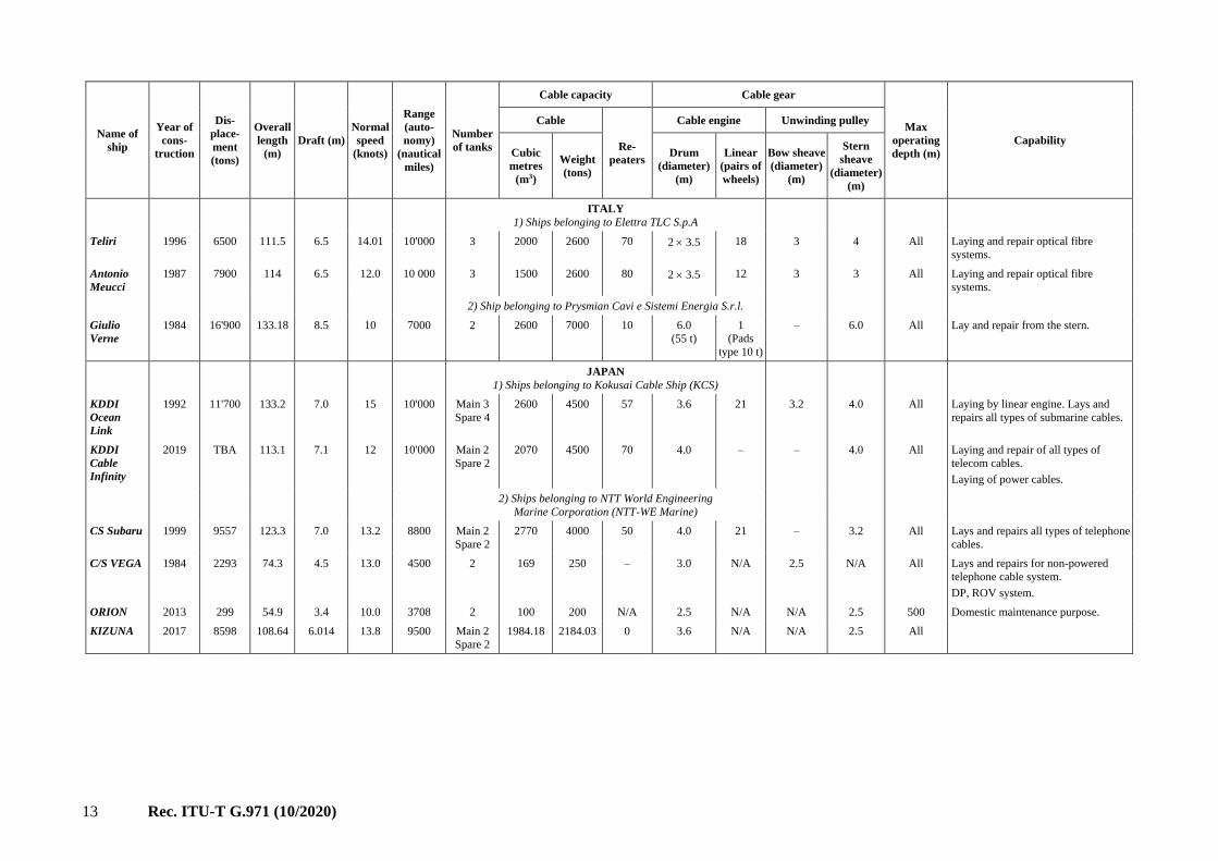
I.1 Cable ships
Cable ships are used for laying optical submarine cables and also for repairing optical submarine
cables, including repeaters. A cable ship contains a cable tank, a cable engine and an
unwinding/winding pulley. The cable tank houses wind optical submarine cable and repeaters. The
cable engine controls the unwinding/winding speed so that it synchronizes well with the ship's speed.
Unwinding/winding pulleys are installed at the bow and/or stern of the ship, and are called bow and
stern sheaves, respectively.
The cable ship also carries submersible equipment for underwater work. Generally, a dynamic
positioning (DP) system is used, and it maintains the position of the ship at a fixed point
automatically, without the use of an anchor.

11 Rec. ITU-T G.971 (10/2020)
Name of
ship
Year of
cons-
truction
Dis-
place-
ment
(tons)
Overall
length
(m)
Draft (m)
Normal
speed
(knots)
Range
(auto-
nomy)
(nautical
miles)
Number
of tanks
Cable capacity Cable gear
Max
operating
depth (m)
Capability
Cable
Re-
peaters
Cable engine Unwinding pulley
Cubic
metres
(m3)
Weight
(tons)
Drum
(diameter)
(m)
Linear
(pairs of
wheels)
Bow sheave
(diameter)
(m)
Stern
sheave
(diameter)
(m)
CHINA
1) Ship belonging to China Submarine Cable
Construction Co.,Ltd.
Feng Yang
Hai Gong
2010 1916.5 57.6 2.6 10 - 1 350 800 3 - 10 - - 2000 FYHG is capable of deploying a 5 m
sea plough within WD200 m.
2) Ships belonging to S.B.Submarine Systems Ltd.
CS Fu Hai 2000 9850 105.8 12.0 12.5 45 days 2 tanks
2 hold
2736.8
548
5200
1042
96 3.0 20 - 2 3.0 All Laying and repair optical fibre
systems.
Bold
Maverick
2001 9850 105.8 12.0 12.5 45 days 2 tanks
2 hold
2736.8
548
5200
1042
96 3.0 20 - 2 3.0 All Laying and repair optical fibre
systems.
CS Fu An 1982 10380 141.5 11.6 12.0 38 days 3 tanks
1 hold
1200
120
2394
309
35 2 x 3.0 - - 2 3.0 All Laying and repair optical fibre
systems.
DENMARK
Ships belonging to Tele Denmark
Peter Faber 1982 3680 78.35 Ice
3.8
Summer
5.0
13.0 7000 1 tank
1 hold
310
230
600
400
App.
10
3.0 2 3.0 – 4000 Reinforced for operation in ice-filled
waters.
A-frame for ROV. Two hydraulic
double-drum warping winches.
Lodbrog 1985/
2002
12'503 143.4 8.50 16.0 10'000 6 2940 5040 84 2 4.0
(25 t)
2 6
(6 t)
– 2 3.0 All Laying/burying and repair of all types
of cables (coaxial, optical fibre and
power cables).
ROV capability, SWL 8 tonne.
FINLAND
1) Ship belonging to Sonera Ltd
M/S
Telepaatti
1978
(modifi-
cation)
450 42.6 3.0 12 – 1 – 350 – 2 linear
engines with
3 caterpillar
tracks on
each
3.0 300 Laying of all types of telecom cables.
Specially equipped for cable route
survey and cable repair. Fully
automatic autopilot and DP-system.

12 Rec. ITU-T G.971 (10/2020)
Name of
ship
Year of
cons-
truction
Dis-
place-
ment
(tons)
Overall
length
(m)
Draft (m)
Normal
speed
(knots)
Range
(auto-
nomy)
(nautical
miles)
Number
of tanks
Cable capacity Cable gear
Max
operating
depth (m)
Capability
Cable
Re-
peaters
Cable engine Unwinding pulley
Cubic
metres
(m3)
Weight
(tons)
Drum
(diameter)
(m)
Linear
(pairs of
wheels)
Bow sheave
(diameter)
(m)
Stern
sheave
(diameter)
(m)
2) Ship belonging to YIT Primatel
c/s
Telepaatti
1978
Modifi-
cation
1999
450 42.6 3.0 10.5 – 1 250 260 – – 2 linear
engines
with
3 cater-
pillar
tracks on
each
3.0 – 300 Laying of all types of telecom cables
and < 150 mm power cables.
Specially equipped for cable route
survey and cable repair.
Fully automatic autopilot and
DP-system.
FRANCE
1) Ships belonging to France Telecom Marine
Chamarel
(formerly
Vercors)
1974 11'000 136 7.2 16.0 12'000 3 2425 4900 144 3.0 24 3.0 Chute All Laying and repair of all types of
telecom cables.
Burying of cables with plough and
200 kW Hector 4.
Léon
Thevenin
1983 6800 107 6.24 15.0 10'000 2 + 1 1420 2000 11 3.4 12 3.0 Chute All Laying and repair of all types of
telecom cables.
Burying of cables using 300 kW
Hector 5.
Raymond
Croze
1983 6800 107 6.24 15.0 10'000 2 + 1 1420 2000 11 3.4 12 3.0 Chute All Laying and repair of all types of
telecom cables.
Burying of cables using 250 kW
Hector 3.
René
Descartes
2002 15'450 114.50 7.42 16.0 12'000 4 3250 5500 210 4.0 20 Aft sheave
3.0 m
Sheave All Stem concept cable ship. Laying and
repair of all types of telecom cables.
Burying of cables with plough and
250 kW ROV Hector 6.
2) Ships belonging to Alda Marine
Ile de Sein
Ile de Batz
Ile de
Brehat
2002 18'006 140.4 8.016 15.0 15'000 2 + 2 3000 5500 202 4.0 21 NA 3.0 All Laying and repair of all types of
telecom cables.
Burying of cables with. 2/3m Rock
plough. Sea state 7 A-frame.
Ile de Ré 1983
rebuilt
2002
12'687 143.4 7.23 16.0 11'000 3 + 3 2900 4500 84 2 × 4.0 NA NA 3.0 All Laying and repair of types of cable.
ROV to 2500 m. A plough is
available.
13 Rec. ITU-T G.971 (10/2020)
Name of
ship
Year of
cons-
truction
Dis-
place-
ment
(tons)
Overall
length
(m)
Draft (m)
Normal
speed
(knots)
Range
(auto-
nomy)
(nautical
miles)
Number
of tanks
Cable capacity Cable gear
Max
operating
depth (m)
Capability
Cable
Re-
peaters
Cable engine Unwinding pulley
Cubic
metres
(m3)
Weight
(tons)
Drum
(diameter)
(m)
Linear
(pairs of
wheels)
Bow sheave
(diameter)
(m)
Stern
sheave
(diameter)
(m)
ITALY
1) Ships belonging to Elettra TLC S.p.A
Teliri 1996 6500 111.5 6.5 14.01 10'000 3 2000 2600 70 2 3.5 18 3 4 All Laying and repair optical fibre
systems.
Antonio
Meucci
1987 7900 114 6.5 12.0 10 000 3 1500 2600 80 2 3.5 12 3 3 All Laying and repair optical fibre
systems.
2) Ship belonging to Prysmian Cavi e Sistemi Energia S.r.l.
Giulio
Verne
1984 16'900 133.18 8.5 10 7000 2 2600 7000 10 6.0
(55 t)
1
(Pads
type 10 t)
– 6.0 All Lay and repair from the stern.
JAPAN
1) Ships belonging to Kokusai Cable Ship (KCS)
KDDI
Ocean
Link
1992 11'700 133.2 7.0 15 10'000 Main 3
Spare 4
2600 4500 57 3.6 21 3.2 4.0 All Laying by linear engine. Lays and
repairs all types of submarine cables.
KDDI
Cable
Infinity
2019 TBA 113.1 7.1 12 10'000 Main 2
Spare 2
2070 4500 70 4.0 – – 4.0 All Laying and repair of all types of
telecom cables.
Laying of power cables.
2) Ships belonging to NTT World Engineering
Marine Corporation (NTT-WE Marine)
CS Subaru 1999 9557 123.3 7.0 13.2 8800 Main 2
Spare 2
2770 4000 50 4.0 21 – 3.2 All Lays and repairs all types of telephone
cables.
C/S VEGA 1984 2293 74.3 4.5 13.0 4500 2 169 250 – 3.0 N/A 2.5 N/A All Lays and repairs for non-powered
telephone cable system.
DP, ROV system.
ORION 2013 299 54.9 3.4 10.0 3708 2 100 200 N/A 2.5 N/A N/A 2.5 500 Domestic maintenance purpose.
KIZUNA 2017 8598 108.64 6.014 13.8 9500 Main 2
Spare 2
1984.18 2184.03 0 3.6 N/A N/A 2.5 All

14 Rec. ITU-T G.971 (10/2020)
Name of
ship
Year of
cons-
truction
Dis-
place-
ment
(tons)
Overall
length
(m)
Draft (m)
Normal
speed
(knots)
Range
(auto-
nomy)
(nautical
miles)
Number
of tanks
Cable capacity Cable gear
Max
operating
depth (m)
Capability
Cable
Re-
peaters
Cable engine Unwinding pulley
Cubic
metres
(m3)
Weight
(tons)
Drum
(diameter)
(m)
Linear
(pairs of
wheels)
Bow sheave
(diameter)
(m)
Stern
sheave
(diameter)
(m)
UNITED KINGDOM
1) Ship belonging to British Telecommunications plc
Sovereign 1991 13'018 131 7.0 13.5 14'000 4 2800 6200 90 3.50 3.00 3.50 All Lays, repairs all types of coaxial and
optical fibre cable.
(operated by C&W marine.)
2) Ships belonging to Global Marine Systems Ltd
Ditto (no plough).
MV Cable
Installer
1980 6065 89.42 5 12 42 days 4 840 1600 None 3.0 4-track
pair
– 3.0 – Repeaterless installation vessel fully
DP Cegelec 901 system.
Seaspread 1980 10'887 116 6.8 13 65 days 2 1010 1701 – 2 3 – – 3 All Lays/repairs by aft drums. Burial by
plough. Lays/repairs armoured and
lightweight cables.
Pacific
Guardian
1984 7526 116 6.32 14.0 8000 3 1416 3470 96 3.5 3.00 3.00 All Laying by linear cable engine.
Lays and repairs armoured and
lightweight cables.
Sir Elic
Sharp
1988 7526 115 6.3 13.5 9600 3 1416 1700 96 2 3.5 – 3 3 All Laying by linear cable engine. Repairs
and lays armoured and lightweight
cables. Post lay/repair burial by
integral ROV.
3) Ship belonging to Global Marine Systems Ltd
MV Cable
Innovator
1995 – 142 8.3 14.5 42 days 4 4900 7500 180 4.0 21 pairs
(min)
– 4.0 – Simplex D/P system.
Lays/repairs cables.
MARSHALL ISLANDS
1) Ship belonging to TE CONNECTIVITY SUBCOM, SLU.
Teneo 1992 4000 81 5.7 13 4200 2 435 1000 20 2 3.5 1 9 2 3 1 3 All Lays and repairs of all types of
telephone cables.
2) Ship belonging to CS Tyco Decisive, Inc.
CS Decisive 2003 16148 140 8.4 13.9 25000 3 Main 1138.6 8841 2 x ODIM
4.0
ODIM
20pair
- 30T 0.6m
2x 50T 1.15
80T .046
- The Decisive is capable of deploying
SubCom's ROVs; Triton STs and
SMD Nereus and SubCom's 3 m
ploughs up to 80T bollard pull.

15 Rec. ITU-T G.971 (10/2020)
Name of
ship
Year of
cons-
truction
Dis-
place-
ment
(tons)
Overall
length
(m)
Draft (m)
Normal
speed
(knots)
Range
(auto-
nomy)
(nautical
miles)
Number
of tanks
Cable capacity Cable gear
Max
operating
depth (m)
Capability
Cable
Re-
peaters
Cable engine Unwinding pulley
Cubic
metres
(m3)
Weight
(tons)
Drum
(diameter)
(m)
Linear
(pairs of
wheels)
Bow sheave
(diameter)
(m)
Stern
sheave
(diameter)
(m)
3) Ship belonging to CS Tyco Dependable, Inc.
CS
Dependable
2002 16148 139.1 8.4 13.9 25000 3 Main 1138.6 8841 2 x ODIM
4.0
ODIM
20pair
- 30T 0.6m
2x 50T
1.15
80T .046
- The Dependable is capable of
deploying SubCom's ROVs; Triton
STs and SMD Nereus and SubCom's
3 m ploughs up to 80T bollard pull.
4) Ship belonging to CS Tyco Durable, Inc.
CS Durable 2003 16148 139.1 8.4 13.9 25000 3 Main 1138.6 8841 2 x ODIM
4.0
ODIM
20pair
- 30T 0.6m
2x 50T
1.15
80T .046
- The Durable is capable of deploying
SubCom's ROVs; Triton STs and
SMD Nereus and SubCom's 3 m
ploughs up to 80T bollard pull.
5) Ship belonging to CS Tyco Reliance, Inc.
CS
Reliance
2001 16148 140 8..4 13.9 25000 3 Main 1138.6 8841 2 x ODIM
4.0
ODIM
20pair
- 30T 0.6m
2x 50T
1.15
80T .046
- The Reliance is capable of deploying
SubCom's ROVs; Triton STs and
SMD Nereus and SubCom's 3 m
ploughs up to 80T bollard pull.
6) Ship belonging to CS Tyco Resolute, Inc.
CS
Resolute
2002 16148 140 8.4 13.9 25000 3 Main 1138.6 8841 2 x ODIM
4.0
ODIM
20pair
- 30T 0.6m
2x 50T
1.15
80T .046
- The Resolute is capable of deploying
SubCom's ROVs; Triton STs and
SMD Nereus and SubCom's 3 m
ploughs up to 80T bollard pull.
7) Ship belonging to CS Tyco Responder, Inc.
CS
Responder
2001 16148 140 8.4 13.9 25000 3 Main 1138.6 8841 2 x ODIM
4.0
ODIM
20pair
- 30T 0.6m
2x 50T
1.15
80T .046
-
UNITED STATES OF AMERICA
Ship belonging to Transceanic Cable Ship Company, LLC.
CS Global
Sentinel
1991 16118 145.7 8.08 15 10'000 3 main,
4 spare
3258
(main,
total)
164
(spare,
total)
6098 100+ 2 3.7 1
Dowty
21 pairs
2 3 1 trough/
Chute type
– The Global Sentinel is capable of
deploying TRITON ST ROVs, as well
as SMD 1.5 m sea ploughs.

16 Rec. ITU-T G.971 (10/2020)
Name of
ship
Year of
cons-
truction
Dis-
place-
ment
(tons)
Overall
length
(m)
Draft (m)
Normal
speed
(knots)
Range
(auto-
nomy)
(nautical
miles)
Number
of tanks
Cable capacity Cable gear
Max
operating
depth (m)
Capability
Cable
Re-
peaters
Cable engine Unwinding pulley
Cubic
metres
(m3)
Weight
(tons)
Drum
(diameter)
(m)
Linear
(pairs of
wheels)
Bow sheave
(diameter)
(m)
Stern
sheave
(diameter)
(m)
UNITED ARAB EMIRATES
Ships belonging to E-marine PJSC
CS Etisalat 1990 2221 74.7 4.5 13 35 days 3 667 600 12 3 6 3 4 Unlimited Surface lay, maintenance, ROV
inspection and jet burial.
CS NIWA 1990 16'375 145.66 8.08 15 60 days 3 main
4 spare
3258 6098 152 4 18 4 4 Unlimited Surface lay, plough burial,
maintenance, work class ROV
inspection and jet burial.
CS UAA 1972
Conver-
ted in
1996
7800 133.7 6.15 13 48 days 3 main
1 spare
3360 4500 120 4 18 4 4 Unlimited Surface lay, plough, maintenance,
work class ROV inspection and jet
burial.
REPUBLIC OF KOREA
Ships belonging to KT Submarine
SEGERO 1998 8323 115 7.8 12 4 4500 2218 70ea 2 4 2 4 – 3.6
Responder 2000 8071 105.5 9.1 12.5 – 4 4790 6000 – – – – – –
MALTA
1) Ship belonging to J. Ray Mcdermott (Norway) AS Of Oslo
Norway (as registered owner)
NORTH
OCEAN
102
2008 11680
Gross
Tons
118.97
(length according
to Article
2(8) of the
Internation
al Tonnage
Convention
Moulded
Draught
(Reg 4(2)
6.70
15 Not
known
(N/K)
N/K N/K N/K N/K N/K N/K N/K N/K N/K --
2) Ship belonging to Oceanteam Bourbon 4 AS, Tveitarasveien 12,
5232 Paradis Bergen 1201, Norway
SOUTHER
N OCEAN
2010 11014 119.07 6.85 15 -- -- -- -- -- -- -- -- -- -- --
3) Ship belonging to Oceanteam Bourbon 101 AS, Tveitarasveien
12, 5232 Paradis Bergen 1201, Norway
BOURBON
OCEANTE
AM 101
2007 8575 106.20 5.50 15 – – – – – – – – – –
4) Prysmian Powerlink Services Limited, Chickenhall Lane,
Eastleigh, Hampshire SO506YU, United Kingdom
ULISSE 2010 10490 115.23 5.33 – – – – – – – – – – –

17 Rec. ITU-T G.971 (10/2020)
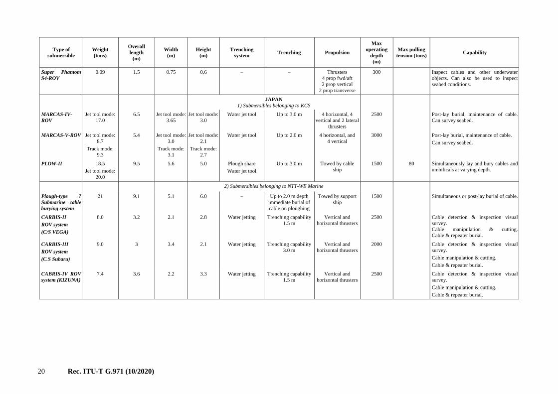
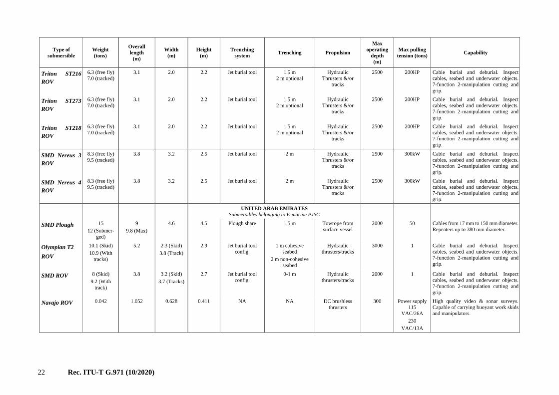
I.2 Submersible equipment
Various types of submersible equipment are used to support the installation and maintenance of an optical submarine cable system. Typical examples of
submersible equipment include a plough and a remotely operated vehicle (ROV).
A plough is towed by a cable ship and is used to lay the optical submarine cable while burying it.
An ROV is used when a plough is not available. A submersible craft assisting repair and burial (SCARAB) is a type of ROV. ROVs typically enable
inspection, repair, and burial.
Type of
submersible
Weight
(tons)
Overall
length
(m)
Width
(m)
Height
(m)
Trenching
system Trenching Propulsion
Max
operating
depth
(m)
Max pulling
tension (tons) Capability
CHINA
1) Submersible belonging to China Submarine Cable Construction Co.,Ltd.
SHARK-600
Submersible
Plough system
12 11.01 4.42 2 Water jet tool Max burial depth: 5m Towed 200 25T Lay and bury all types of cables.
2) Submersibles belonging to S.B. Submarine Systems Ltd.
SMD MD3 25 10.3 5.1
4.7 Articulated towed
plough system
3 m Towed by ship 1500 80T
SMD Hi- Plough 27 10.3 5.1 7.5 Injecting/Jetting Up to 3.25 m Towed by ship 200 20 T
ROV SEA LION
6.5 3.2 2.9 2.9 Jet burial tool 1.5 m
Hydraulic Thrusters
&/or tracks
2500 200HP Cable burial and deburial. Inspect cables,
seabed and underwater objects. 7-
function 2-manipulation cutting and
grip.
ROV SEA LION
III
Free Fly
17.25
Tracked
18.4
6.5 Free Fly
3.7
Tracked
5.2
3.1 Jet burial tool 3.0 m
Hydraulic Thrusters
&/or tracks
2500 600HP Cable burial and deburial. Inspect cables,
seabed and underwater objects. 7-
function 2-manipulation cutting and
grip.
FRANCE
Submersibles belonging to France Telecom Marine
ELISE2
Submersible
Plough system
17 7.60 2.90 2.95 Ploughshare Immediate burial up
to 1.1 m
Towed by support
ship
1500 Lay and bury all types of cables.
ELISE3
Submersible
Plough system
17 7.60 2.90 2.95 Ploughshare Immediate burial up
to 1.1 m
Towed by support
ship
1500 Lay and bury all types of cables.
Self-advancing
buried system
CASTOR2
12 7.0 2.40 3.00 Trenching wheel or
chain
Burial of existing
cables down to 2 m
Tracked vehicle 1000 Burial of cables and pipes.
Visual inspection.

18 Rec. ITU-T G.971 (10/2020)
Type of
submersible
Weight
(tons)
Overall
length
(m)
Width
(m)
Height
(m)
Trenching
system Trenching Propulsion
Max
operating
depth
(m)
Max pulling
tension (tons) Capability
ROVs HECTOR
3, 4, 5 & 6
9 4.0 3.50 2.10 High-pressure
water jets
Up to 1.5 m depth Thrusters
(inspection)
Back drive
(burial)
2000 Visual inspection, post-lay burial, cable
location, cable manipulation, cable
cutting.
Remote control
submersible
Scorpio 2000
3.4 2.9 1.5 2.11 High-pressure
water jets
Up to 60 cm depth
Thrusters 1000 Visual inspection, post-lay burial, cable
location/manipulation/cutting.
ITALY
Submersibles belonging to Elettra TLC SpA
Plough Taurus 1 14 9 4.6 4.5 Plough share Up to 1 m Towed by cable
ship
1500 50 Lay and bury all types of cables.
Plough Taurus 2 16 9.5 4.5 5.1 Plough share Up to 1.5 m Towed by cable
ship
1500 50 Lay and bury all types of cables.
ROV – Phoenix 2 6.8 4.8 2 2.6 High/low-pressure
jetting
Up to 1.2 m 8 Hydraulic
thrusters
1000 Visual inspection, post-lay burial, cable
location/manipulation/cutting.
ROV-T200 Free-fly mode
6, Track mode
7
3.1 2 2.2 High/low-pressure
jetting
Up to 1.2 m 4 vertical and 4
horizontal thrusters
2500 Visual inspection, post-lay burial, cable
location/manipulation/cutting.
UNITED KINGDOM
Submersibles belonging to Global Marine Systems Ltd
Submersible
trencher
17.0 6.6 4 3.4 Fluidization and
cutting jets and
dredge pump
Up to 1 m depth with
cutting and
fluidization jets
Three vertical and
four horizontal
thrusters, track drive
differential steering
274 Trench in existing cable
and pipe.
Submersible
Plough system
9.75 6.1 2.6 2.6 Ploughshare
proceeded by disc
Immediate burial of
cable on ploughing
Towed by support
ship
900 Lay and bury cable, umbilical and pipe
in one action giving full cable protection.
Remote control
submersible 2 off
Cirus A&B
3.2 3.5 2.1 2.3 Water jets Trenching capability
0.3 m
Thrusters (7) 1000 Visual inspection, cable
location/inspection/deburial,
manipulation.
Tools include cable cutter, cable gripper
and two manipulators with line cutters.
Plough
2 off A&B
14.5 9 4.1 4 Passive blade Trenching capability
1.0 m
Towed 1000 Steerable, repeater burial.
Remote control
submersible
ROV 128
7.5 2.9 1.8 2.0 Jetting tool Trenching capability
0.6 m
Tracked burial
Thrusters survey
1000 (burial)
2000 (survey)
Tools include cable cutter, cable gripper
and two manipulators with line cutters.

19 Rec. ITU-T G.971 (10/2020)
Type of
submersible
Weight
(tons)
Overall
length
(m)
Width
(m)
Height
(m)
Trenching
system Trenching Propulsion
Max
operating
depth
(m)
Max pulling
tension (tons) Capability
Underwater
vehicle- MARLIN
7.8 4.191 2.438 3.175 Burial skid To 1.0 m
(Optimized for
0-30 kPa soil)
Hydraulic driven
thrusters
2500 Burial, deburial, inspection.
Maintenance and repair.
Tools include cable cutter, cable gripper.
Scarab I –
Umbilically
tethered ROV
3.2 2.74 1.82 1.52 Jetting tool Up to 0.6 m Thrusters:
2 vertical
4 vectored
2000 Cable detection and inspection. Visual
survey.
Cable manipulation and cutting.
Debris elimination.
Cable and repeater burial/deburial.
Subtrack – ROV 10.0 8.0 (Max) 3.7 3.8 Jetting tool Burial to 1.0 m Electro-hydraulic
track drives
1000 Cable burial and deburial. Inspection.
Maintenance and repair.
EUREKA:
Deepwater burial
+ trenching
system
17 (Max) 5.5 4.2 3.85 Jetting tool
Rock wheel cutter
Mechanical chain
excavator
1 m
1.2 m
2.2 m
Electro-hydraulic
track drives
1500 Capable of burying cable, small flexible
flowlines and also rigid pipes. Can also
debury cable and restore.
Visual and electronic inspections.
Plough 5 14.0 9.0 4.6 3.7 Passive blade Variable from
0-1100 mm
(600-900 mm
in all conditions)
Towed 1000 Simultaneously lay and bury cables and
umbilicals at varying depths.
Plough 6 and 7 14.0 9.0 4.6 3.7 Passive blade Max burial
depth:
1100 mm
Towed 1000 Simultaneously lay and bury cables and
umbilicals at varying depths.
Cable Plough
1000 mm
14.4 9.75 4.1 3.9 Passive blade 1000 mm
(Good conditions:
1100 mm;
Repeaters/Joints:
500 mm)
Towed 1000 Simultaneously lay and bury cables and
umbilicals at varying depths.
DENMARK
Submersibles belonging to Telecom Denmark
Plough D 13.5 9.0 4.6 3.7 Plough share Variable from
0-1100 mm (600-900
mm in all conditions)
Towed by host
vessel
1500 Lay and bury telecom cables, power
cables and umbilicals.
Cables: Up to 120 mm (bury).
Joints and repeaters:
Up to 400 mm (pass).
Plough 7 13.5 9.0 4.6 3.7 Plough share Variable from
0-1100 mm
(600-900 mm
in all conditions)
Towed by
surface vessel
1000 Lay and bury fibre optic cables, power
cables and umbilicals.
Subtrack-
Subsea tractor
10.0 8.0 (Max) 3.7 3.8 Jetting tool Burial to 1.0 m Electro-hydraulic
track drives
1000 Cable burial and deburial.
Inspection.
Maintenance and repair.
20 Rec. ITU-T G.971 (10/2020)
Type of
submersible
Weight
(tons)
Overall
length
(m)
Width
(m)
Height
(m)
Trenching
system Trenching Propulsion
Max
operating
depth
(m)
Max pulling
tension (tons) Capability
Super Phantom
S4-ROV
0.09 1.5 0.75 0.6 – – Thrusters
4 prop fwd/aft
2 prop vertical
2 prop transverse
300 Inspect cables and other underwater
objects. Can also be used to inspect
seabed conditions.
JAPAN
1) Submersibles belonging to KCS
MARCAS-IV-
ROV
Jet tool mode:
17.0
6.5 Jet tool mode:
3.65
Jet tool mode:
3.0
Water jet tool Up to 3.0 m 4 horizontal, 4
vertical and 2 lateral
thrusters
2500 Post-lay burial, maintenance of cable.
Can survey seabed.
MARCAS-V-ROV Jet tool mode:
8.7
Track mode:
9.3
5.4 Jet tool mode:
3.0
Track mode:
3.1
Jet tool mode:
2.1
Track mode:
2.7
Water jet tool Up to 2.0 m 4 horizontal, and
4 vertical
3000 Post-lay burial, maintenance of cable.
Can survey seabed.
PLOW-II 18.5
Jet tool mode:
20.0
9.5 5.6 5.0 Plough share
Water jet tool
Up to 3.0 m Towed by cable
ship
1500
80 Simultaneously lay and bury cables and
umbilicals at varying depth.
2) Submersibles belonging to NTT-WE Marine
Plough-type 7
Submarine cable
burying system
21 9.1 5.1 6.0 – Up to 2.0 m depth
immediate burial of
cable on ploughing
Towed by support
ship
1500 Simultaneous or post-lay burial of cable.
CARBIS-II
ROV system
(C/S VEGA)
8.0 3.2 2.1 2.8 Water jetting
Trenching capability
1.5 m
Vertical and
horizontal thrusters
2500 Cable detection & inspection visual
survey.
Cable manipulation & cutting.
Cable & repeater burial.
CARBIS-III
ROV system
(C.S Subaru)
9.0 3 3.4 2.1 Water jetting Trenching capability
3.0 m
Vertical and
horizontal thrusters
2000 Cable detection & inspection visual
survey.
Cable manipulation & cutting.
Cable & repeater burial.
CABRIS-IV ROV
system (KIZUNA)
7.4 3.6 2.2 3.3 Water jetting Trenching capability
1.5 m
Vertical and
horizontal thrusters
2500 Cable detection & inspection visual
survey.
Cable manipulation & cutting.
Cable & repeater burial.

21 Rec. ITU-T G.971 (10/2020)
Type of
submersible
Weight
(tons)
Overall
length
(m)
Width
(m)
Height
(m)
Trenching
system Trenching Propulsion
Max
operating
depth
(m)
Max pulling
tension (tons) Capability
UNITED STATES OF AMERICA
Submersibles belonging to TE CONNECTIVITY SUBCOM, SLU.
Arado 1 14.0 10.5 6.0 4.3 Towed plough
system
1.5 m burial Towed by ship.
1 thruster for
launches and
recoveries
1400 ARADO 1 is a towed burial tool
employing state-of-the-art burial
features. It can achieve 1.5 m burial
depth in up to 1 400 m water depth.
SMD MD3 25 9.3 5.0 4.4 Articulated
towed plough
system
3 m Towed by ship 1500 80T
SMD MD3 DF 25 9.3 5.0 4.4 Articulated
towed plough
system
3 m Towed by ship 1500 80T
SeaStallion 1 32 13.8 5.4 5.3 Towed plough
system
3 m Towed by ship 2000 100T
SeaStallion 2 32 13.8 5.4 5.3 Towed plough
system
3 m Towed by ship 2000 100T
SeaStallion 3 32 13.8 5.4 5.3 Towed plough
system
3 m Towed by ship 2000 100T
SeaStallion 4 32 13.8 5.4 5.3 Towed plough
system
3 m Towed by ship 2000 100T
SeaStallion
SEP
12 8.0 4.2 4.0 Towed plough
system
2 m Towed by ship 1000 50 Sea Stallion SEP is a dedicated Shore
End Plough.
SMD QT800 21 (free fly)
22 (tracked)
5.4 4.6 3.3 Jet burial tool 3 m Hydraulic
Thrusters &/or
tracks
2500 800HP Cable burial and deburial. Inspect
cables, seabed and underwater objects.
7-function 2-manipulation cutting and
grip.
Triton ST213
ROV
6.3 (free fly)
7.0 (tracked)
3.1 2.0 2.2 Jet burial tool 1.5 m
2 m optional
Hydraulic
Thrusters &/or
tracks
2500 200HP Cable burial and deburial. Inspect
cables, seabed and underwater objects.
7-function 2-manipulation cutting and
grip.
Triton ST214
ROV
6.3 (free fly)
7.0 (tracked)
3.1 2.0 2.2 Jet burial tool 1.5 m
2 m optional
Hydraulic
Thrusters &/or
tracks
2500 200HP Cable burial and deburial. Inspect
cables, seabed and underwater objects.
7-function 2-manipulation cutting and
grip.
Triton ST215
ROV
6.3 (free fly)
7.0 (tracked)
3.1 2.0 2.2 Jet burial tool 1.5 m
2 m optional
Hydraulic
Thrusters &/or
tracks
2500 200HP Cable burial and deburial. Inspect
cables, seabed and underwater objects.
7-function 2-manipulation cutting and
grip.
22 Rec. ITU-T G.971 (10/2020)
Type of
submersible
Weight
(tons)
Overall
length
(m)
Width
(m)
Height
(m)
Trenching
system Trenching Propulsion
Max
operating
depth
(m)
Max pulling
tension (tons) Capability
Triton ST216
ROV
6.3 (free fly)
7.0 (tracked)
3.1 2.0 2.2 Jet burial tool 1.5 m
2 m optional
Hydraulic
Thrusters &/or
tracks
2500 200HP Cable burial and deburial. Inspect
cables, seabed and underwater objects.
7-function 2-manipulation cutting and
grip.
Triton ST273
ROV
6.3 (free fly)
7.0 (tracked)
3.1 2.0 2.2 Jet burial tool 1.5 m
2 m optional
Hydraulic
Thrusters &/or
tracks
2500 200HP Cable burial and deburial. Inspect
cables, seabed and underwater objects.
7-function 2-manipulation cutting and
grip.
Triton ST218
ROV
6.3 (free fly)
7.0 (tracked)
3.1 2.0 2.2 Jet burial tool 1.5 m
2 m optional
Hydraulic
Thrusters &/or
tracks
2500 200HP Cable burial and deburial. Inspect
cables, seabed and underwater objects.
7-function 2-manipulation cutting and
grip.
SMD Nereus 3
ROV
8.3 (free fly)
9.5 (tracked)
3.8 3.2 2.5 Jet burial tool 2 m Hydraulic
Thrusters &/or
tracks
2500 300kW Cable burial and deburial. Inspect
cables, seabed and underwater objects.
7-function 2-manipulation cutting and
grip.
SMD Nereus 4
ROV
8.3 (free fly)
9.5 (tracked)
3.8 3.2 2.5 Jet burial tool 2 m Hydraulic
Thrusters &/or
tracks
2500 300kW Cable burial and deburial. Inspect
cables, seabed and underwater objects.
7-function 2-manipulation cutting and
grip.
UNITED ARAB EMIRATES
Submersibles belonging to E-marine PJSC
SMD Plough 15
12 (Submer-
ged)
9
9.8 (Max)
4.6 4.5 Plough share 1.5 m Towrope from
surface vessel
2000 50 Cables from 17 mm to 150 mm diameter.
Repeaters up to 380 mm diameter.
Olympian T2
ROV
10.1 (Skid)
10.9 (With
tracks)
5.2 2.3 (Skid)
3.8 (Track)
2.9 Jet burial tool
config.
1 m cohesive
seabed
2 m non-cohesive
seabed
Hydraulic
thrusters/tracks
3000 1 Cable burial and deburial. Inspect
cables, seabed and underwater objects.
7-function 2-manipulation cutting and
grip.
SMD ROV 8 (Skid)
9.2 (With
track)
3.8 3.2 (Skid)
3.7 (Tracks)
2.7 Jet burial tool
config.
0-1 m Hydraulic
thrusters/tracks
2000 1 Cable burial and deburial. Inspect
cables, seabed and underwater objects.
7-function 2-manipulation cutting and
grip.
Navajo ROV 0.042 1.052 0.628 0.411 NA NA DC brushless
thrusters
300 Power supply
115
VAC/26A
230
VAC/13A
High quality video & sonar surveys.
Capable of carrying buoyant work skids
and manipulators.

23 Rec. ITU-T G.971 (10/2020)
Type of
submersible
Weight
(tons)
Overall
length
(m)
Width
(m)
Height
(m)
Trenching
system Trenching Propulsion
Max
operating
depth
(m)
Max pulling
tension (tons) Capability
REPUBLIC OF KOREA
Submersibles belonging to KT Submarine
ROV 18 5.5 3.7 3.2 3 M 800 HP 2500
Plough 16 9.0 4.1 4.6 – 1.5 M – 1500
Burial 19 5322 4183 2977 – – 300 HP 2500 –
24 Rec. ITU-T G.971 (10/2020)
Bibliography
[b-ITU-T G.975] Recommendation ITU-T G.975 (2000), Forward error correction for
submarine systems.
[b-ITU-T G.975.1] Recommendation ITU-T G.975.1 (2004), Forward error correction for high
bit-rate DWDM submarine systems, including Cor.1 (2006) and Cor.2
(2013).
[b-ITU-T G.976] Recommendation ITU-T G.976 (2014), Test methods applicable to optical
fibre submarine cable systems.
[b-ITU-T G.978] Recommendation ITU-T G.978 (2010), Characteristics of optical fibre
submarine cables.
[b-ITU-T G.979] Recommendation ITU-T G.979 (2016), Characteristics of monitoring
systems for optical submarine cable systems.
[b-ITU-T G Suppl.41] ITU-T G-series Recommendations – Supplement 41 (2018), Design
guidelines for optical fibre submarine cable systems.


Printed in Switzerland Geneva, 2021
SERIES OF ITU-T RECOMMENDATIONS
Series A Organization of the work of ITU-T
Series D Tariff and accounting principles and international telecommunication/ICT economic and
policy issues
Series E Overall network operation, telephone service, service operation and human factors
Series F Non-telephone telecommunication services
Series G Transmission systems and media, digital systems and networks
Series H Audiovisual and multimedia systems
Series I Integrated services digital network
Series J Cable networks and transmission of television, sound programme and other multimedia
signals
Series K Protection against interference
Series L Environment and ICTs, climate change, e-waste, energy efficiency; construction, installation
and protection of cables and other elements of outside plant
Series M Telecommunication management, including TMN and network maintenance
Series N Maintenance: international sound programme and television transmission circuits
Series O Specifications of measuring equipment
Series P Telephone transmission quality, telephone installations, local line networks
Series Q Switching and signalling, and associated measurements and tests
Series R Telegraph transmission
Series S Telegraph services terminal equipment
Series T Terminals for telematic services
Series U Telegraph switching
Series V Data communication over the telephone network
Series X Data networks, open system communications and security
Series Y Global information infrastructure, Internet protocol aspects, next-generation networks,
Internet of Things and smart cities
Series Z Languages and general software aspects for telecommunication systems