izmir institute of technology department of architecture ar231 fall12/13 15.10.2015 dr. engin aktaş...
TRANSCRIPT
IZMIR INSTITUTE OF TECHNOLOGYIZMIR INSTITUTE OF TECHNOLOGY Department of ArchitectureDepartment of Architecture AR23AR2311 Fall12/13Fall12/13
21.04.23 Dr. Engin Aktaş 1
Analysis of the StructuresAnalysis of the Structures

IZMIR INSTITUTE OF TECHNOLOGYIZMIR INSTITUTE OF TECHNOLOGY Department of ArchitectureDepartment of Architecture AR23AR2311 Fall12/13Fall12/13
21.04.23 Dr. Engin Aktaş 2
Introduction• For the equilibrium of structures made of several
connected parts, the internal forces as well the external forces are considered.
• In the interaction between connected parts, Newton’s 3rd Law states that the forces of action and reaction between bodies in contact have the same magnitude, same line of action, and opposite sense.
• Three categories of engineering structures are considered:
a) Frames: contain at least one one multi-force member, i.e., member acted upon by 3 or more forces.
b) Trusses: formed from two-force members, i.e., straight members with end point connections
c) Machines: structures containing moving parts designed to transmit and modify forces.

IZMIR INSTITUTE OF TECHNOLOGYIZMIR INSTITUTE OF TECHNOLOGY Department of ArchitectureDepartment of Architecture AR23AR2311 Fall12/13Fall12/13
21.04.23 Dr. Engin Aktaş 3
Definition of a Truss• A truss consists of straight members connected at
joints. No member is continuous through a joint.
• Bolted or welded connections are assumed to be pinned together. Forces acting at the member ends reduce to a single force and no couple. Only two-force members are considered.
• Most structures are made of several trusses joined together to form a space framework. Each truss carries those loads which act in its plane and may be treated as a two-dimensional structure.
• When forces tend to pull the member apart, it is in tension. When the forces tend to compress the member, it is in compression.
IZMIR INSTITUTE OF TECHNOLOGYIZMIR INSTITUTE OF TECHNOLOGY Department of ArchitectureDepartment of Architecture AR23AR2311 Fall12/13Fall12/13
21.04.23 Dr. Engin Aktaş 4
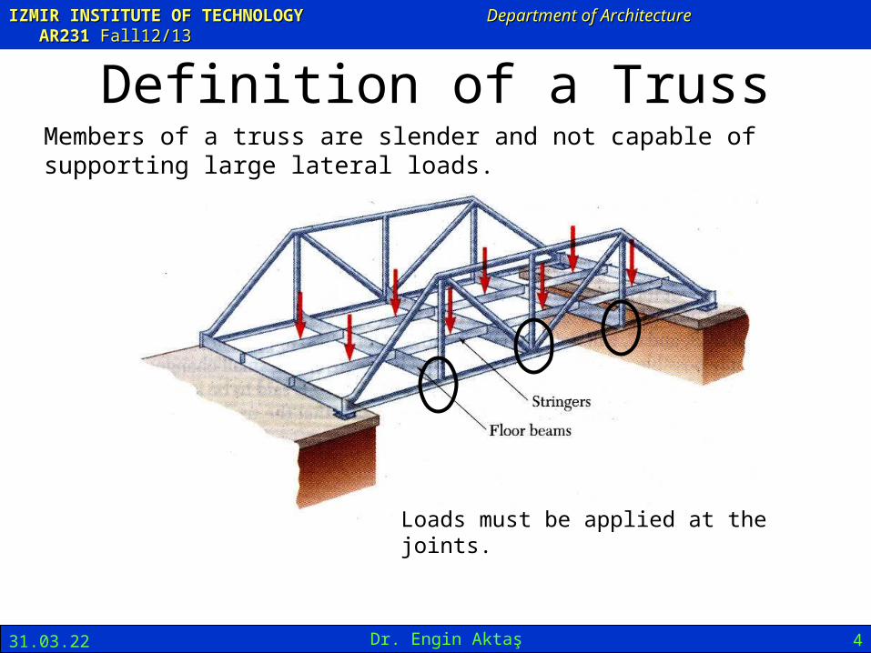
Definition of a TrussMembers of a truss are slender and not capable of supporting large lateral loads.
Loads must be applied at the joints.

IZMIR INSTITUTE OF TECHNOLOGYIZMIR INSTITUTE OF TECHNOLOGY Department of ArchitectureDepartment of Architecture AR23AR2311 Fall12/13Fall12/13
21.04.23 Dr. Engin Aktaş 5
Definition of a Truss
IZMIR INSTITUTE OF TECHNOLOGYIZMIR INSTITUTE OF TECHNOLOGY Department of ArchitectureDepartment of Architecture AR23AR2311 Fall12/13Fall12/13
21.04.23 Dr. Engin Aktaş 6

IZMIR INSTITUTE OF TECHNOLOGYIZMIR INSTITUTE OF TECHNOLOGY Department of ArchitectureDepartment of Architecture AR23AR2311 Fall12/13Fall12/13
21.04.23 Dr. Engin Aktaş 7

IZMIR INSTITUTE OF TECHNOLOGYIZMIR INSTITUTE OF TECHNOLOGY Department of ArchitectureDepartment of Architecture AR23AR2311 Fall12/13Fall12/13
21.04.23 Dr. Engin Aktaş 8

IZMIR INSTITUTE OF TECHNOLOGYIZMIR INSTITUTE OF TECHNOLOGY Department of ArchitectureDepartment of Architecture AR23AR2311 Fall12/13Fall12/13
21.04.23 Dr. Engin Aktaş 9
IZMIR INSTITUTE OF TECHNOLOGYIZMIR INSTITUTE OF TECHNOLOGY Department of ArchitectureDepartment of Architecture AR23AR2311 Fall12/13Fall12/13
21.04.23 Dr. Engin Aktaş 10
IZMIR INSTITUTE OF TECHNOLOGYIZMIR INSTITUTE OF TECHNOLOGY Department of ArchitectureDepartment of Architecture AR23AR2311 Fall12/13Fall12/13
21.04.23 Dr. Engin Aktaş 11
IZMIR INSTITUTE OF TECHNOLOGYIZMIR INSTITUTE OF TECHNOLOGY Department of ArchitectureDepartment of Architecture AR23AR2311 Fall12/13Fall12/13
21.04.23 Dr. Engin Aktaş 12
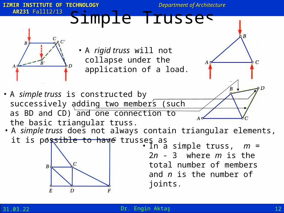
Simple Trusses
• A rigid truss will not collapse under the application of a load.
• A simple truss is constructed by successively adding two members (such as BD and CD) and one connection to the basic triangular truss.
• In a simple truss, m = 2n - 3 where m is the total number of members and n is the number of joints.
• A simple truss does not always contain triangular elements, it is possible to have trusses as

IZMIR INSTITUTE OF TECHNOLOGYIZMIR INSTITUTE OF TECHNOLOGY Department of ArchitectureDepartment of Architecture AR23AR2311 Fall12/13Fall12/13
21.04.23 Dr. Engin Aktaş 13
• Dismember the truss and create a freebody diagram for each member and pin.
• The two forces exerted on each member are equal in magnitude, have the same line of action, and opposite sense.
• Forces exerted by a member on the pins or joints at its ends are directed along the member and equal in magnitude and opposite.
• Conditions of equilibrium on the pins provide 2n equations for 2n unknowns. For a simple truss, 2n = m + 3. May solve for m member forces and 3 reaction forces at the supports.
• Conditions for equilibrium for the entire truss provide 3 additional equations which are not independent of the pin equations.
Analysis of Trusses by the Method of Joints
IZMIR INSTITUTE OF TECHNOLOGYIZMIR INSTITUTE OF TECHNOLOGY Department of ArchitectureDepartment of Architecture AR23AR2311 Fall12/13Fall12/13
21.04.23 Dr. Engin Aktaş 14
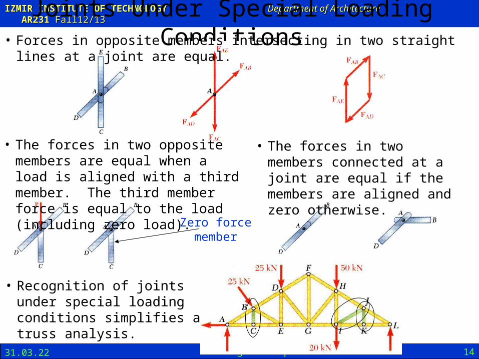
Joints Under Special Loading Conditions• Forces in opposite members intersecting in two straight lines at a joint are equal.
• The forces in two opposite members are equal when a load is aligned with a third member. The third member force is equal to the load (including zero load).
• The forces in two members connected at a joint are equal if the members are aligned and zero otherwise.
• Recognition of joints under special loading conditions simplifies a truss analysis.
Zero force member

IZMIR INSTITUTE OF TECHNOLOGYIZMIR INSTITUTE OF TECHNOLOGY Department of ArchitectureDepartment of Architecture AR23AR2311 Fall12/13Fall12/13
21.04.23 Dr. Engin Aktaş 15
Space Trusses• An elementary space truss consists of 6 members
connected at 4 joints to form a tetrahedron.
• A simple space truss is formed and can be extended when 3 new members and 1 joint are added at the same time.
• Equilibrium for the entire truss provides 6 additional equations which are not independent of the joint equations.
• In a simple space truss, m = 3n - 6 where m is the number of members and n is the number of joints.
• Conditions of equilibrium for the joints provide 3n equations. For a simple truss, 3n = m + 6 and the equations can be solved for m member forces and 6 support reactions.

IZMIR INSTITUTE OF TECHNOLOGYIZMIR INSTITUTE OF TECHNOLOGY Department of ArchitectureDepartment of Architecture AR23AR2311 Fall12/13Fall12/13
21.04.23 Dr. Engin Aktaş 16
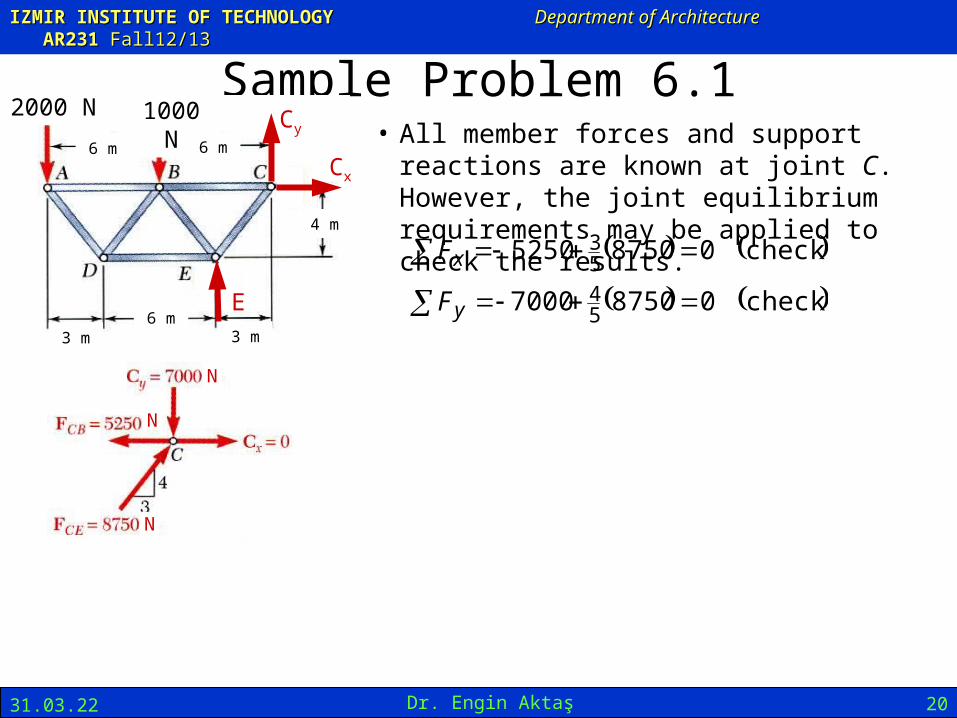
Sample Problem 6.1
Using the method of joints, determine the force in each member of the truss.
SOLUTION:
• Draw the free-body diagram of the entire truss, and using that solve the 3 equilibrium equations for the reactions at E and C.
• Start with Joint A since it is subjected to only two unknown member forces. Determine these from the joint equilibrium requirements.
• Continue with solving unknown member forces at joints D, B, and E from joint equilibrium requirements.
• All member forces and support reactions are known at joint C. However, the joint equilibrium requirements may be applied to check the results.
1000 N2000 N
6 m 6 m
3 m6 m
3 m
4 m

IZMIR INSTITUTE OF TECHNOLOGYIZMIR INSTITUTE OF TECHNOLOGY Department of ArchitectureDepartment of Architecture AR23AR2311 Fall12/13Fall12/13
21.04.23 Dr. Engin Aktaş 17
Sample Problem 6.1
N 000,10E
SOLUTION:
• Draw the free-body diagram of the entire truss, and using that solve the 3 equilibrium equations for the reactions at E and C.
m 3m6N 1000m 12N 2000
0
E
M C
N 000,10E
xx CF 0 0xC
yy CF N 10,000 N 1000 - N 20000
N 7000yC
1000 N2000 N
6 m 6 m
3 m6 m
3 m
4 m
E
Cy
Cx
NCy 7000

IZMIR INSTITUTE OF TECHNOLOGYIZMIR INSTITUTE OF TECHNOLOGY Department of ArchitectureDepartment of Architecture AR23AR2311 Fall12/13Fall12/13
21.04.23 Dr. Engin Aktaş 18
1000 N2000 N
6 m 6 m
3 m6 m
3 m
4 m
E
Cy
Cx
Sample Problem 6.1
• Start with Joint A since it is subjected to only two unknown member forces. Determine these from the joint equilibrium requirements.
534
N 2000 ADAB FF
ompressionF
ensionF
AD
AB
C
T
N 2500
N 1500
• There are now only two unknown member forces at joint D.
DADE
DADB
FF
FF
532
CF
TF
DE
DB
N 3000
N 2500
N
N
N

IZMIR INSTITUTE OF TECHNOLOGYIZMIR INSTITUTE OF TECHNOLOGY Department of ArchitectureDepartment of Architecture AR23AR2311 Fall12/13Fall12/13
21.04.23 Dr. Engin Aktaş 19
1000 N2000 N
6 m 6 m
3 m6 m
3 m
4 m
E
Cy
Cx
Sample Problem 6.1
• There are now only two unknown member forces at joint B. Assume both are in tension.
N 3750
250010000 54
54
BE
BEy
F
FF
CFBE N 3750
N 5250
3750250015000 53
53
BC
BCx
F
FF
TFBC N 5250
• There is one unknown member force at joint E. Assume the member is in tension.
N 8750
375030000 53
53
EC
ECx
F
FF
CFEC N 8750
N
N
N
N
N
N
IZMIR INSTITUTE OF TECHNOLOGYIZMIR INSTITUTE OF TECHNOLOGY Department of ArchitectureDepartment of Architecture AR23AR2311 Fall12/13Fall12/13
21.04.23 Dr. Engin Aktaş 20
Sample Problem 6.1• All member forces and support reactions are
known at joint C. However, the joint equilibrium requirements may be applied to check the results.
checks 087507000
checks 087505250
54
53
y
x
F
F
N
N
N
1000 N2000 N
6 m 6 m
3 m6 m
3 m
4 m
E
Cy
Cx

IZMIR INSTITUTE OF TECHNOLOGYIZMIR INSTITUTE OF TECHNOLOGY Department of ArchitectureDepartment of Architecture AR23AR2311 Fall12/13Fall12/13
21.04.23 Dr. Engin Aktaş 21
Trusses Made of Several Simple Trusses• Compound trusses are statically
determinant, rigid, and completely constrained.
32 nm
• Truss contains a redundant member and is statically indeterminate.
32 nm
• Necessary but insufficient condition for a compound truss to be statically determinant, rigid, and completely constrained,
nrm 2
non-rigid rigid32 nm
• Additional reaction forces may be necessary for a rigid truss.
42 nm

IZMIR INSTITUTE OF TECHNOLOGYIZMIR INSTITUTE OF TECHNOLOGY Department of ArchitectureDepartment of Architecture AR23AR2311 Fall12/13Fall12/13
21.04.23 Dr. Engin Aktaş 22
Analysis of Trusses by the Method of Sections
• When the force in only one member or the forces in a very few members are desired, the method of sections works well.
• To determine the force in member BD, pass a section through the truss as shown and create a free body diagram for the left side.
• With only three members cut by the section, the equations for static equilibrium may be applied to determine the unknown member forces, including FBD.
IZMIR INSTITUTE OF TECHNOLOGYIZMIR INSTITUTE OF TECHNOLOGY Department of ArchitectureDepartment of Architecture AR23AR2311 Fall12/13Fall12/13
21.04.23 Dr. Engin Aktaş 23
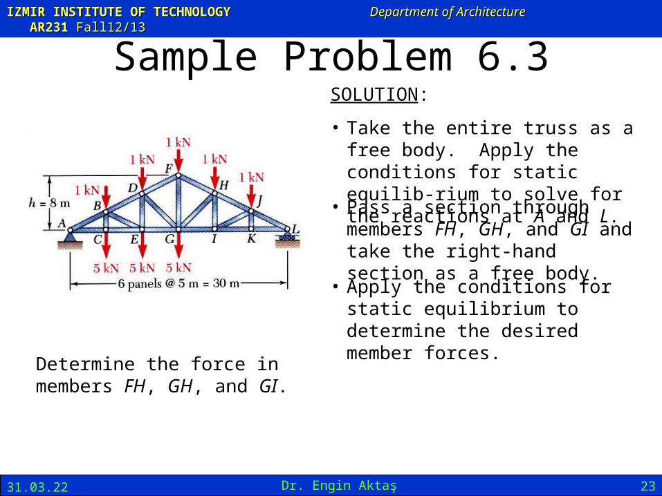
Sample Problem 6.3
Determine the force in members FH, GH, and GI.
SOLUTION:
• Take the entire truss as a free body. Apply the conditions for static equilib-rium to solve for the reactions at A and L.
• Pass a section through members FH, GH, and GI and take the right-hand section as a free body.
• Apply the conditions for static equilibrium to determine the desired member forces.
IZMIR INSTITUTE OF TECHNOLOGYIZMIR INSTITUTE OF TECHNOLOGY Department of ArchitectureDepartment of Architecture AR23AR2311 Fall12/13Fall12/13
21.04.23 Dr. Engin Aktaş 24
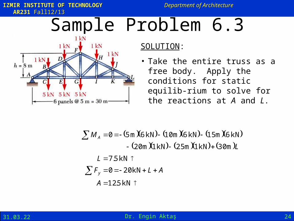
Sample Problem 6.3SOLUTION:
• Take the entire truss as a free body. Apply the conditions for static equilib-rium to solve for the reactions at A and L.
kN 5.12
kN 200
kN 5.7
m 30kN 1m 25kN 1m 20
kN 6m 15kN 6m 10kN 6m 50
A
ALF
L
L
M
y
A

IZMIR INSTITUTE OF TECHNOLOGYIZMIR INSTITUTE OF TECHNOLOGY Department of ArchitectureDepartment of Architecture AR23AR2311 Fall12/13Fall12/13
21.04.23 Dr. Engin Aktaş 25
Sample Problem 6.3• Pass a section through members FH, GH, and GI
and take the right-hand section as a free body.
N
kN 13.13
0m 33.5m 5kN 1m 10kN 7.50
0
GI
GI
H
F
F
M
• Apply the conditions for static equilibrium to determine the desired member forces.
TFGI kN 13.13
N

IZMIR INSTITUTE OF TECHNOLOGYIZMIR INSTITUTE OF TECHNOLOGY Department of ArchitectureDepartment of Architecture AR23AR2311 Fall12/13Fall12/13
21.04.23 Dr. Engin Aktaş 26
Sample Problem 6.3
kN 82.13
0m 8cos
m 5kN 1m 10kN 1m 15kN 7.5
0
07.285333.0m 15
m 8tan
FH
FH
G
F
F
MGL
FG
CFFH kN 82.13
kN 371.1
0m 15cosm 5kN 1m 10kN 1
0
15.439375.0m 8
m 5tan
32
GH
GH
L
F
F
M
HI
GI
CFGH kN 371.1
N
IZMIR INSTITUTE OF TECHNOLOGYIZMIR INSTITUTE OF TECHNOLOGY Department of ArchitectureDepartment of Architecture AR23AR2311 Fall12/13Fall12/13
21.04.23 Dr. Engin Aktaş 27
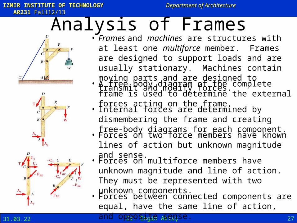
Analysis of Frames• Frames and machines are structures with at least one
multiforce member. Frames are designed to support loads and are usually stationary. Machines contain moving parts and are designed to transmit and modify forces.
• A free body diagram of the complete frame is used to determine the external forces acting on the frame.
• Internal forces are determined by dismembering the frame and creating free-body diagrams for each component.
• Forces between connected components are equal, have the same line of action, and opposite sense.
• Forces on two force members have known lines of action but unknown magnitude and sense.
• Forces on multiforce members have unknown magnitude and line of action. They must be represented with two unknown components.

IZMIR INSTITUTE OF TECHNOLOGYIZMIR INSTITUTE OF TECHNOLOGY Department of ArchitectureDepartment of Architecture AR23AR2311 Fall12/13Fall12/13
21.04.23 Dr. Engin Aktaş 28
Frames Which Cease To Be Rigid When Detached From Their Supports
• Some frames may collapse if removed from their supports. Such frames can not be treated as rigid bodies.
• A free-body diagram of the complete frame indicates four unknown force components which can not be determined from the three equilibrium conditions.
• The frame must be considered as two distinct, but related, rigid bodies.
• With equal and opposite reactions at the contact point between members, the two free-body diagrams indicate 6 unknown force components.
• Equilibrium requirements for the two rigid bodies yield 6 independent equations.

IZMIR INSTITUTE OF TECHNOLOGYIZMIR INSTITUTE OF TECHNOLOGY Department of ArchitectureDepartment of Architecture AR23AR2311 Fall12/13Fall12/13
21.04.23 Dr. Engin Aktaş 29
Sample Problem 6.4
Members ACE and BCD are connected by a pin at C and by the link DE. For the loading shown, determine the force in link DE and the components of the force exerted at C on member BCD.
SOLUTION:
• Create a free-body diagram for the complete frame and solve for the support reactions.
• Define a free-body diagram for member BCD. The force exerted by the link DE has a known line of action but unknown magnitude. It is determined by summing moments about C.
• With the force on the link DE known, the sum of forces in the x and y directions may be used to find the force components at C.
• With member ACE as a free-body, check the solution by summing moments about A.
IZMIR INSTITUTE OF TECHNOLOGYIZMIR INSTITUTE OF TECHNOLOGY Department of ArchitectureDepartment of Architecture AR23AR2311 Fall12/13Fall12/13
21.04.23 Dr. Engin Aktaş 30
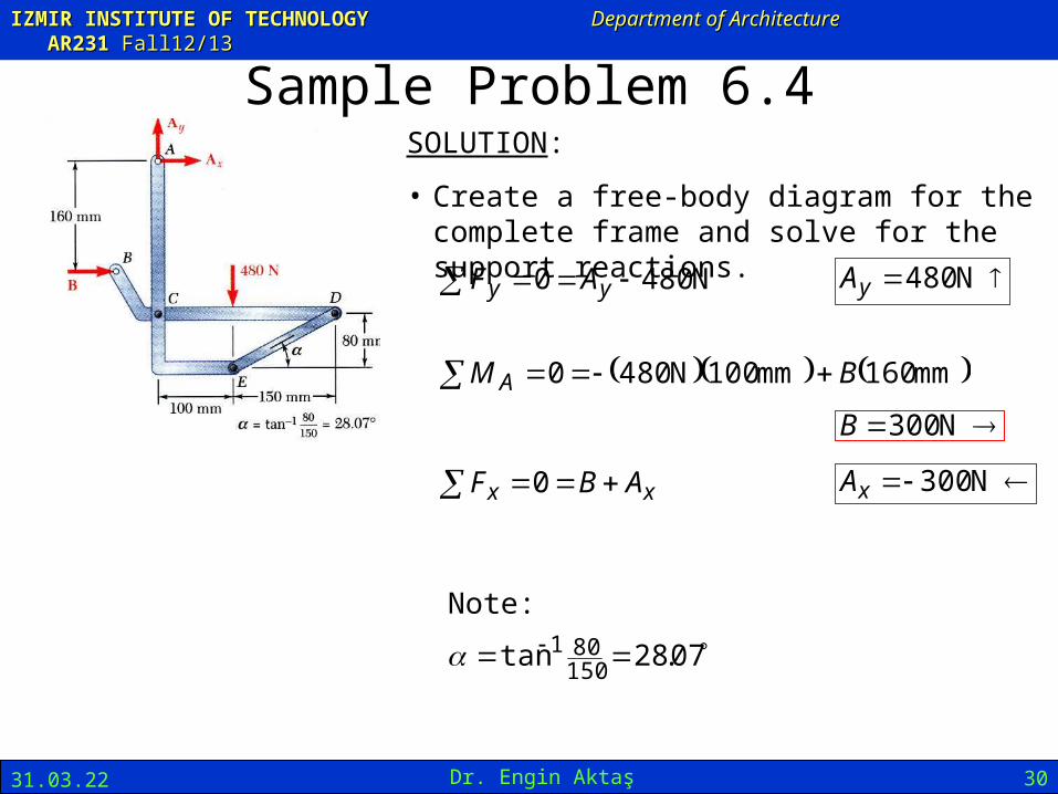
Sample Problem 6.4SOLUTION:
• Create a free-body diagram for the complete frame and solve for the support reactions.
N 4800 yy AF N 480yA
mm 160mm 100N 4800 BM A N 300B
xx ABF 0 N 300xA
07.28tan150801
Note:
IZMIR INSTITUTE OF TECHNOLOGYIZMIR INSTITUTE OF TECHNOLOGY Department of ArchitectureDepartment of Architecture AR23AR2311 Fall12/13Fall12/13
21.04.23 Dr. Engin Aktaş 31
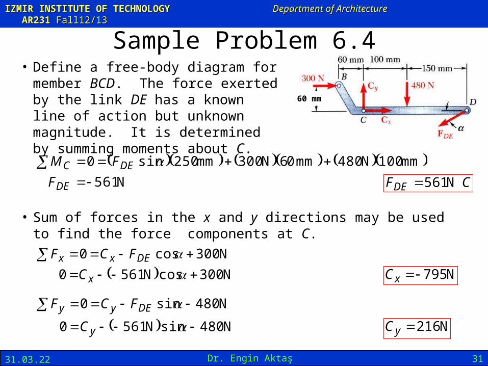
Sample Problem 6.4• Define a free-body diagram for member
BCD. The force exerted by the link DE has a known line of action but unknown magnitude. It is determined by summing moments about C.
N 561
mm 100N 480mm 06N 300mm 250sin0
DE
DEC
F
FM CFDE N 561
• Sum of forces in the x and y directions may be used to find the force components at C.
N 300cosN 561 0
N 300cos0
x
DExx
C
FCF
N 795xC
N 480sinN 5610
N 480sin0
y
DEyy
C
FCF
N 216yC
60 mm

IZMIR INSTITUTE OF TECHNOLOGYIZMIR INSTITUTE OF TECHNOLOGY Department of ArchitectureDepartment of Architecture AR23AR2311 Fall12/13Fall12/13
21.04.23 Dr. Engin Aktaş 32
Sample Problem 6.4
• With member ACE as a free-body, check the solution by summing moments about A.
0mm 220795mm 100sin561mm 300cos561
mm 220mm 100sinmm 300cos
xDEDEA CFFM
(checks)