jaeri1 -tech jp0250564 2002-083
TRANSCRIPT
JAERI1 -Tech JP0250564
2002-083
STUDY FOR REDUCING RADIOACTIVE SOLID WASTE ATITER DECOMMISSIONING PERIOD
Shinichi SATO*, Masanori ARAKI, Junji OHMORI, samnu OHNO
Satoshi SATO, NMichinori YAMAUJCI-I and Takeo NISHITAN1
Japan Atomic Energy Research Institute
Arn®PW~tr±(±,HtJ~)Jf r3fIJf~d 1.0 3t *R (T319- 1195 I5
ThA kht) -C, ts3 P L L R 5 ' fi o~:lHitd A j~~t#t97- (319-1195 $D tftH )+Jrf t )t4 :IThs
This report is issued irregularly.
Inquiries about availability of the reports should be addressed to Research
Information Division, Department of Intellectual Resources, Japan Atomic Energy
Research Institute, Tokai-mura, Naka-gun, Ibaraki-ken T319i1l95, Japan.
© Japan Atomic Energy Research Institute, 2002

JAERI-Tech 2002 -083
Study for Reducing Radioactive Solid Waste at ITERDecommissioning Period
Shinichi SATO*, Masanori ARAKI, Juniji OH-MORI, Isamu OHNO,
Satoshi SATO+, Michinori YAMAUCHI+ and Takeo NISITANI+
Department of ITER Project
Naka Fusion Research Establishment
Japan Atomic Energy Research Institute
Naka-machi, Naka-gun, Ibaraki-ken
(Received September 4, 2002)
It is one of the foremost goals for ITER to demonstrate the attractiveness with regard to
safety and environmental potential. This implies that the radioactive materials and waste
at decommissioning phase should carefully be treated with prescribed regulations.
As possible activities during the Coordinated Technical Activity (CIA), the authors have
performed a feasibility study for searching the possibility of effective reduction in the
activated level as reasonably achievable as possible by taking account of minimum material
changes while keeping original design concept and structure. Major induced aivation in
ITER comes from activated nickel and cobalt so that it is effective for the major structural
components to minimize their material contents. Employing less Ni and Co steel in place
of high-Ni austenitic stainless steel for blanket shield block, vacuum vessel shield material
and TF coil casing has been considered as one of the effective plans to reduce the activated
materials at the decommissioning phase. In this study, two less-Ni austenitic stainless
steels are evaluated; one is high-Mn austenitic stainless steel JK2 which is developing for
jacket material of ITER CS coil and the other is S204L/ASTM-XM- 1 1 which is also high-Mn
steel specified in the popular standards such as American Society of Testing and Material
(ASTM).
*:current address; Kawasaki Heavy Industry Co. Ltd.
+: Departmnent of Fusion Engineering Research

JAERI-Tech 2002-083
Based on the material changes, activation analyses have been performed to investigate the
possibility of reducing radioactive wastes. As a most impressive result, at 40 years after the
termination some of main components such as a TF coil casing will reach to the clearance
level which is specified by IAEA, and most components will be categorized into extremely
low level waste except for limited components. These results will give the appropriate short
decommissioning period that is assumed to start at 100 years after the termination in the
original design.
Keywords: ITER, Decommissioning, Radwaste, Clearance, High-Mn Steel, Activation Level

JAFRI-Tech 2002 -083
I T E R ~tWf 9XI -MM -- )fkC
(2002 -9fA 4 F]~
I T E RO 1tcnH 01DUZ -CttetfftwPA A 3~j-lh
I T ER ~tA#h tU-C, I
ITER~~~~~~~~~~~~~
frQ44{LA o: JttcR L fi F e9i LtRC0 I9~~ It te{ 0 P MC Ut:
+ :Ut V"KP

This is a blank page.

JAERI-Tech 2002-083
Contents
I. Introduction..................... 1
2. Activation Analysis..................... 2
2.1 Analysis Condition..................... 2
2.2 Analysis Results..................... 5
3. Clearance Potential of Components. ............... 20
3.1 Clearance Level..................... 20
3.2 Clearance Indices.....................21
4. Activation Level of Radwaste.................30
4.1 Classification of Radwaste.................30
4.2 Categorization of Radwaste.................30
5. Preliminary Estimation of the Amount of Radioactive Wastes .... 41
6. Conclusions..................... 43
Acknowledgements.....................44
References..................... 44
Appendix - 1.....................45
Appendix - 2.....................59
Appendix - 3..................... 73
Appendix- 4.....................77

JAERI-Tech 2002-083
2.1 JtIf-4~t- .. . ..... 2
2.2 )W )-T~v-X- . . . . . . . . . . . . . . . . . 5
†.. . . . . . . . . . . . . . . . . . . 20
3.1 Y'7t>KV5\A. ................... 20
3. 2 >U 7t>7t... .... ... ... 21
4. . . .4.L.<) .. ............ 30
4.1 .4..$.. .t .. ..t#. .30
4.2tkIItti$. ................... 30
5. . . . . . . . . . . . . . . . . . 4 1
†.J . . . . . . . . . . 43
.. . . . . . . . . . 44
. . . . . .. . . . . . . . . .44
fist-i.~~ .... .... ... 4 5
vi

JAERI-Tech 2002-083
1. Introduction
It is one of the foremost goals for ITER to demonstrate the attractiveness with
regard to safety and environmental potential. This implies that the radioactive
materials and waste at decommissioning phase should be carefully treated with
prescribed regulations. The benefit in the safety and environmental impact of
fusion has been highly noticed. The rad-waste issue is, however, sometimes taken
seriously. In particular, for public environments it is very important to demonstrate
production of less activated wastes for emphasizing the attractiveness of fusion,
especially in ITER.
In the series of 2001 ITER Final Design Report (FDR) documents, activation level
and its weight are roughly estimated. In ITER Generic Site Safety Report (GSSR) [1],
some of large components such as Toroidal Field (TF)/Poloidal Field (PF) coils are
categorized into low level activated components that are close to clearance level
except for conductor at 30 years after shutdown. As possible activities during the
Coordinated Technical Activity (CTA), it is worth performing a feasibility study for
searching the possibility of more reduction in the activated level by taking account of
minimum material changes while keeping original design concept and structure.
Based on it, reassessment of the activation level and the amount of radwaste
volumes will give us positive aspects for public acceptance. Final goal for this
study is to reduce not only the activation level to around one tenth of the current
value but also the amount of radioactive wastes whose radiation level exceeds the
clearance level. In this study ITER decommissioning is assumed to start at 30 - 40
years after final shutdown.
Employing less nickel and cobalt steel in place of high nickel austenitic stainless
steel for blanket shield block, vacuum vessel shield material and TF coil casing has
been considered as one of the effective plans to reduce the activated materials at the
decommissioning phase. It is noted that for application of their materials it is
necessary to provide further evaluations such as the material applicability,
fabricability, compatibility with the related components and acquisition. In
particular the fabricability for magnet structure, the weldability is the most
important issue so that R&D study is intensively ongoing as a part of demonstration
of fabricability for ITER CS jacket material.
In this study, activation analysis including the geometry of major ITER
components is described in section 2 and its results are presented in section 3 and 4.
Based on the assessment, radwaste masses in both cases are briefly estimated and
compared in section 5.
JAERI-Tech 2002-083
2. Activation Analysis
2.1 Analysis Condition
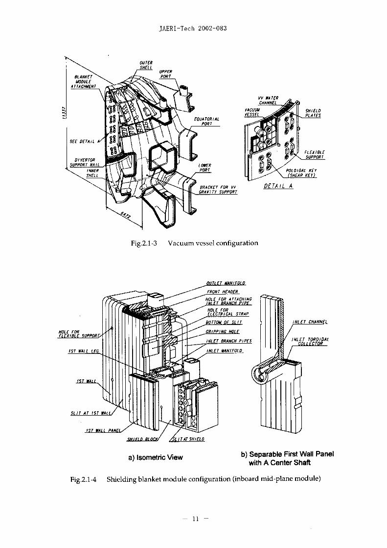
A cross sectional view of ITER tokamak components is shown in Fig.2.1-1.
Configuration of TF coil, vacuum vessel and blanket modules are also shown in Figs.
2.1-2 to 2.1-4. In accordance with the configurations, one-dimensional model is
made for the activation analysis. Basic flow of the activation analysis studied in
this report is shown in Fig.2.1-5. Detailed analysis conditions are shown in the
following sections.
2.1.1 Analysis Case
Activation analyses have been performed to investigate the possibility of reducing
radwaste due to the changes of component materials. Materials combinations in
this analysis are shown in Table2.1-1. Two analysis cases are considered; one is
'High-Ni steel case' of the current design base, the other is 'ligh-Mn steel case'
based on the proposal for reducing the activation level. In the High-Mn case,
materials of blanket shield block, vacuum vessel shield material and TF coil casing
were changed to high-Mn/less-Ni steels. To capture thermal neutron which is
generated through the shielding materials from 14 MeV , boron content in shielding
materials of blanket and vacuum vessel was increased to 4 wt%. In the current
design of vacuum vessel, SS 304 with 2 wt% boron contents is selected as the shield
material except for ferromagnetic (SS430) insert regions (under TF coil in the
outboard area) for reducing toroidal field ripple loss.
2.1.2 Analysis Model
One-dimensional annulus models for inboard and outboard regions were applied
to this analysis both for neutron transport and activation analysis. Radial build-up
of the ITER tokamak components is shown in Fig.2.1-6. Detailed analysis models
for inboard and outboard region are also shown in Fig.2.1-7 and Fig.2.1-8,
respectively. Radial thickness of major components related to the activation
products is listed below;
1) Blanket Module:
8lmm(separable first wall) + 369mm(shielding block)
2) Vacuum Vessel:
Inboard mid-plane:
6Omm(inner shell) + 217mm(shield material) + 6Omm(outer shell)
Outboard mid-plane:
-2-

JAERI-Tech 2002-083
6Omm(inner shell) + 630mm(shield material) + 6Omm(outer shell)
3) TF Coil:
Inboard mid-plane:
75mm(plasma-side casing) + 576mm(winding pack) + 225mm(nose region)
Outboard mid-plane:
124mm(plasma-side casing) + 633mm(winding pack) + 124mm(cryostat-
side casing)
Some regions in the functional materials such as shielding blocks for blanket and
vacuum vessel are modeled as a homogeneous layer.
2.1.3 Chemical Composition of Material
In TER-GSSR, induced activity of main tokamak components at 30 years after
final shutdown is dominated by 'Co and 63Ni. These radionuclides are mainly
produced by the following reactions with thermal and fast neutrons;
For ' 0Co : 5 Co (n, y)60Co, 60Ni (nf,,,, p )60C o
For 6 %N 62Ni (n, y) 63 Ni, 6 CU (nfas, p )6 Ni
In the current design, austenitic stainless steel with high nickel contents is
selected for the main structure of tokamak components. Cobalt around 0.01 to 0.05
weight percent is contained in nickel ore as an impurity. Therefore, if austenitic
steel with low nickel and cobalt contents were used for their components, it would
be expected that activation products of 6 N and 6 Co drastically be decreased,
resulting in lower activation level and smaller amount of radioactive wastes at the
decommissioning phase for an appropriate period. It is also important to add
boron into cooling water or neutron-shield blocks of blanket and vacuum vessel to
reduce the amount of thermal neutrons. Therefore, idea for material changes is to
play roles of reducing the radioactive wastes and its radiation level for TF coil casing
and of reducing activation levels for the shield blocks.
Chemical compositions of materials in this analysis are summarized in Table2.1-2.
For High-Ni steel case (current design), a modified SS316L(N) steel (S EK1) which
contains high nitrogen to achieve high strength is employed as the structural
material of TF coil casing. For the blanket sideld block and vacuum vessel shell,
SS316L(N)-ITER grade with low cobalt(<0.05wt%/) and boron (<0.Olwt%) is used.
Type 304 stainless steel with 2wt%/ boron contents is used for the shield material of
the vacuum vessel.
-3-
JAERI-Tech 2002-083
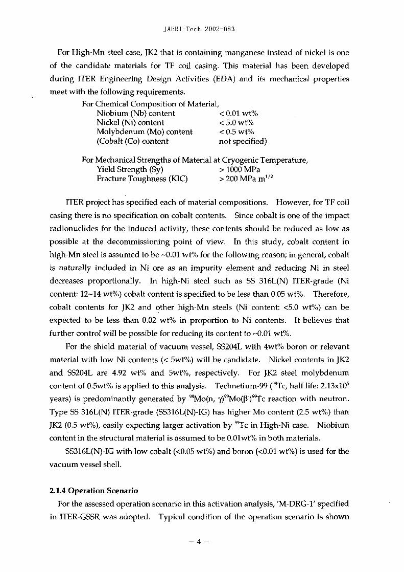
For High-Mn steel case, JK2 that is containing manganese instead of nickel is one
of the candidate materials for TF coil casing. This material has been developed
during ITER Engineering Design Activities (EDA) and its mechanical properties
meet with the following requirements.
For Chemical Composition of Material,Niobium (Nb) content < 0.01 wt%Nickel (Ni) content < 5.0 wt/oMolybdenum (Mo) content < 0.5 wt%(Cobalt (Co) content not specified)
For Mechanical Strengths of Material at Cryogenic Temperature,Yield Strength (Sy) > 1000 MPaFracture Toughness (KIC) > 200 MPa m' /2
ITER project has specified each of material compositions. However, for TF coil
casing there is no specification on cobalt contents. Since cobalt is one of the impact
radionuclides for the induced activity, these contents should be reduced as low as
possible at the decommissioning point of view. In this study, cobalt content in
high-Mn steel is assumed to be -0.01 wt% for the following reason; in general, cobalt
is naturally included in Ni ore as an impurity element and reducing Ni in steel
decreases proportionally. In high-Ni steel such as SS 316L(N) ITER-grade (Ni
content: 12-14 wt%) cobalt content is specified to be less than 0.05 wt%. Therefore,
cobalt contents for JK2 and other high-Mn steels (Ni content: <5.0 wt%) can be
expected to be less than 0.02 wt%/ in proportion to Ni contents. It believes that
further control will be possible for reducing its content to 0.01 wt%.
For the shield material of vacuum vessel, SS204L with 4w% boron or relevant
material with low Ni contents (< wt%) will be candidate. Nickel contents in JK2
and S5204L are 4.92 wt% and 5wt%, respectively. For JK2 steel molybdenum
content of 0.5wt%/ is applied to this analysis. Technetium-99 (Tc, half life: 2.13x10'
years) is predominantly generated by 98Mo(n, y99 Mo(pV)99Tc reaction with neutron.
Type SS 316L(N) ITER-grade (S316L(N)-IG) has higher Mo content (2.5 wt%) than
JK2 (0.5 wt%), easily expecting larger activation by 9 Tc in High-Ni case. Niobium
content in the structural material is assumed to be 0.Olwt% in both materials.
SS316L(N)-IG with low cobalt (<0.05 wt%) and boron (<0.01 wt%) is used for the
vacuum vessel shell.
2.1.4 Operation Scenario
For the assessed operation scenario in this activation analysis, 'M-DRG-1' specified
in ITER-GSSR was adopted. Typical condition of the operation scenario is shown
- 4 -

JAERI-Tech 2002-083
as follows;
1) Operation period:
20 years + 12 days (the first half 10 years + 6 days, the second half 10 years + 6
days)
2) Neutron wall load on FW surface: 0.56 MWM-2 (average)
3) Neutron fluence on FW surface: 0.304 MWa. M 2 (average)
4) Maximum duty cycle for operation: 0.25
5) Assumption of special operation campaign: two 6 days campaigns at 25% duty
cycle at the end of the first and second decades of operation
6) Neutron Fluence build-up :see below
- Neutron Fluence build-up in the first 10 years _______
Years 1-4 5 6 7 8 9 10 Total0.022+I
Neutron Fluence, (MWa M) 0 0.006 0.008 0.012 0.020 0.024 0.0940.002*
- The second 10 years
Years 11-20 Total
2 ~~~~~~~~~~~~0.208+1Neutron Fluence, (MWa~ -M) 0.2100.002* J_ _ _ _
Note) *:Neutron fluence for 6 days campaign with 25% duty cycle
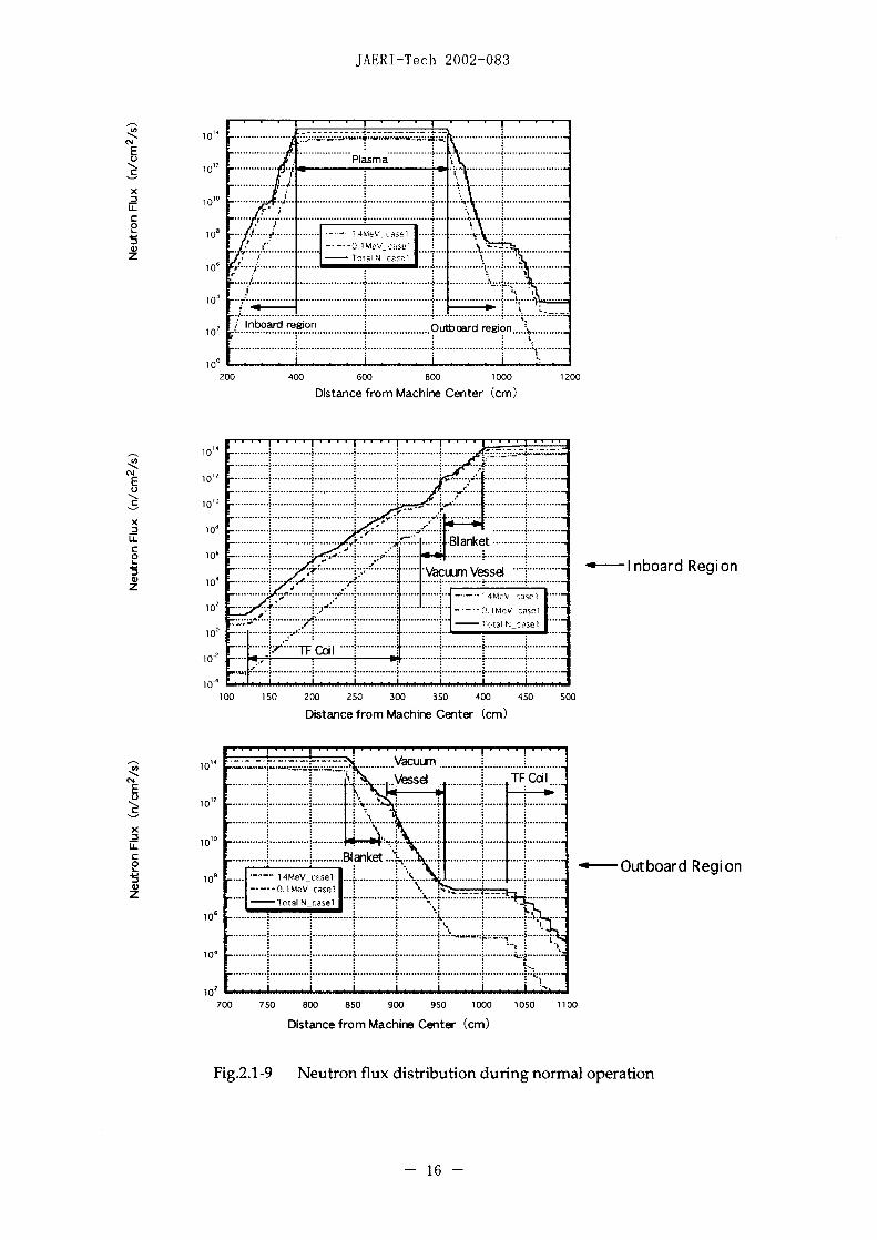
2.1.5 Neutron Flux Distribution
The one dimensional discrete ordinate code ANISIN was used for neutron and
gamma ray transport analysis. The nuclear data was based on FUSION-40. Figure
2.1-9 shows neutron fluxes in the inboard and outboard areas during normal
operation.
2.1.6 Activation Analysis
System code THIDA [2] is applied to the activation analysis. For assessment of
the induced activities from the inside (CS coil) to the outside (TF coil) regions, 21
calculation points are selected as shown in Fig.2.1-10. Basically induced activity of
each component in front and rear surfaces is evaluated.
2.2 Analysis Results
Total pecific activities in the major components are summarized in Table2.2-1.
At the final shutdown the maximum specific activity of 2.92 TBq/cc will be
produced in the blanket shielding material. During cooling period of 30 years, the
specific activity decays more than four orders of magnitude. Figures 2.2-1 to 2.2-4
-5-

JAERI-Tech 2002-083
show relationships between specific activity and decay time after final shutdown for
the inboard components (blanket shield, vacuum vessel shell and TF coil case). Up to
30 years after final shutdown, dominant isotopes that mostly contribute to the
specific activities are as follows;
[For blanket shield]
`5Fe (half life: 2.7 y), H (1 2.3 y), 3 Ni (100.1y), 60Co (5.3y)
[For vacuum vessel]
15 Fe (half life: 2.7 y), 63Ni (100.1y), 'Co (5.3y)
[For TF coil casing]
`5Fe (half life: 2.7 y), H (12.3 y), 63 Ni (100.1y), `0Co (5.3y)
Major neutron reactions for these radioisotopes with regard to activation are
described as follows;5 8Ni(n, np)57Co -*>EC, 0.837MeV (57 Fe, stable)5 4 Fe(i,p)'Mn, 55Mn(ni, 2n)5 Mn --*EC, 1.377MeV (5 4Cr, stable)5 0Cr(n,2n)49 Cr -->f3&EC, 2.628MeV (V, active)49V --*EC, 0.602MeV (49 Tri, stable)54Fe(n, 'y)55Fe, 'Fe(n,2n) 55 Fe , 5 8Ni(n, (x)5 Fe --)EC, 0.2313MeV (Mn, stable)60Ni(n, p)'Co -*1-&,y, 2.824MeV (60Ni, stable)62 Ni(n, y)6 3Ni -1,0.0659MeV (63CU, stable)58Ni(n, y)59Ni -)>EC, 1.073MeV (59Co, stable)
It is noted that radioactive isotopes ` 5Fe and 60Co decay rather fast compared with
the other radioactive components.
Beyond about 100 years, more longer-lived isotopes, 14C (half life: 5.7x 10' y), 9Ni
(7.5x10⁴y), 14Nb (2.0x 10 4 y), 9 Mlo (3.5x10' y) etc. dominate the specific activities. Specific
activities (vs. decay time after final shutdown) of transmutation products in the major
components are attached to Appendix-I1.
-6-
JAERI-Tech 2002-083
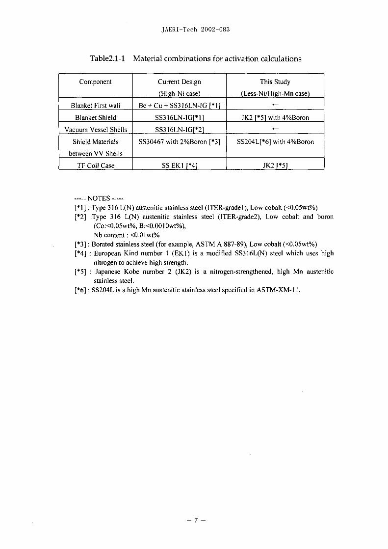
Table2.1-1 Material combinations for activation calculations
Component Current Design This Study
(High-Ni case) (Less-Ni/High-Mn case)
Blanket First wall Be + Cu + SS316LN-IG [Il
Blanket Shield SS3 16LN-1G[* 1 K2 *5 with 4%Boron
Vacuum Vessel Shells SS3I161NAlG[*21
Shield Materials SS30467 with 2%Boron [*3] SS204L-[*6] with 4%Boron
between VV Shells
TF Coil Case SS EKI1 [*41 JK2 [*5]
----NOTES --[*1] Type 316 L(N) austenitic stainless steel (ITER-gradel), Low cobalt (<0.05wt%)[*2] :Type 316 L(N) austenitic stainless steel (ITER-grade2), Low cobalt and boron
(Co:<0.05wt%, B:<0.00]IOwt%),Nb content: <0.0 I wt%
[*3] Borated stainless steel (for example, ASTM A 887-89), Low cobalt (<0.05wt%)[*4] European Kind number (EKI) is a modified SS316L(N) steel which uses high
nitrogen to achieve high strength.[*5] Japanese Kobe number 2 (JK2) is a nitrogen-strengthened, high Mn austenitic
stainless steel.[*61 SS204L is a high Mn austenitic stainless steel specified in ASTMW-XM-1 .
-7-

JAERI-Tech 2002-083
0 00C 0 ~ ~ ~ ~ ~ ~ ~ ~~~~0C
o -o
Ni~~~~~~~~~~~~~~~~~~N
Iv ~~~~~~~~~0
o CU~~~~~~~~~~~~~~~~~~~~~~~~~~0C
II CD~~~~~~~~~~~~~~~~~~~~~C
8 N c0 Nc c Oc Cl-,
U <.Z
A~~~~~~~~~~~~~~~~~~~~~~~~~~~~~~~~~~~~~~~~~~~~~U
8~~~~~~~~~~~~

JAERI-Tech 2002-083
:cl~i-0 coc
+ i + - + ± ± + ± - -i
Cl N in LU N LU LU~~W Wl e L
cu ~~~e LU 4442444444444L
- N ~~ - U W -U Lfl LUL -i 4M L 4~ oV i 4
U-4 Wti W Ui C 4 Wt C Pt3 .~ 4 AUV- ,- r:
-v ~~~W ± - * t -,- + t t 1-~~~~~~~ + ,- -W -444242W 42'444424442m444242444 LiiW l
4W04 . lin - t n N - i LU Cl -W C. -C-.L~~~~ -w.-~~M ,a - ~ 4 L
LU Q LWULW -U - N o tO L U L 0L in4 , -Q CLQ
0 ~~ N LU . 4 ~~~ in en .4 4 U o in .4 LU t 1 01n LU -, Cl LU LU - in -. -. Cl N -ti N~~~~- N - t t Cl
0 ti LU LU ite n.- C~~~~~~~~~~~~U
o Z1 C 0 Cs-C ~~ 424444424444424244444442444244444m4m I 4444r
LU N Cl N U 0.4 LU 4 ~ L U O3~in0 St l a
V- tiN lS U gN it 4 Nin~ ~~ >C >~iAii]4c > >t > l LUA U
Cu K C~~~~~~~~~~~~ AA >* - - - -- - …C~~~~~~~~~~~~~~~~~~~~~r
Ct U t. n N U.- 0- N N t t n

JAERI-Tech 2002-083
CEN TRAL THERMAL -' 10JSH1IELD
SOLENOID SHIELD..........
IN7ERCOiL
PFI TRVCT~EURIDIA
£400 ULL ~ POR T
PFJ4
BLSE AETE
-- --- - - - 10 - - - - - --
JAERI-Tech 2002-083
84A PORT~~~~~~R CC FRvv OTAI
A TTACHMENT ~ ~ ~ ~ ~ NETBANHPIE ILT OOIA
withAU Cnte ShftFig.2.- Sheldin blankt modle cofiguraion (nboar mi-lnemdLE)
- 11 -fA

JAERI-Tech 2002-083
Neutron source conditionNeutron wall load
one-dimensionaFannulus model
~~~ scenariotanpotcacuato
Nerautron spcifiuativit
Ealulation of clrnceineMateril compsition __~al i ACTAi 41Clanclel
Alstiutono specific activityofteadoule
AU : clearance level for that radionuclide
Fig.2.1-5 Flow diagram of the analysis
- 12 -

JAERI-Tech 2002-083
lesseA wnnDReu
TT l~~~~~~~~~~~~~~~~~~~~~~~~~~~~~~~~~~~~~~~~~~l
C14~~~~~~~~~~~~~
M-0~~~~~~~~~~
00~~~~~~~~~~~~~~
.......... ~~~~~~~~~~~~~~~~~~~~~-P0 / so',
- - - -- - - - - - - - - - - - - - - - - - - - - - - - - - -
13~~~~~~~~

JAERI-Tech 2002-083
C
C) i
2
4 C)
-c 4 4-, 0
cc "00.-- ,I-
4 . -- - - - SLA C
C) N N N N N C) I 0I - U-UC). accc
0., 0cc c�--�-,.c cc cc cc.I.-.CU
O 0-oC
N 0Cc '-4-.=2 C)-o
o 0-t -t - E- 44 � cc
c4 C)
�0 jU .00C) -� �4s4cccc cc
-� 4 Cc
__ _ ___ 5 : ;; ;� ___ I C04Z77 777777
I i-mn-� c.- -: 0 -� cc -� cc-C) t C)- U '00 N0000N00 N '00 c NC) �ct cci ccc ci cci cc cc
000cc cc cccc cc cc cc cc cc c� ccZ
TN NNIA SCc Cc C) � � S
z � £�Eno Qooco �*�3*�*eC
N C) C) - -
C)� cc. - -) -�Cc � 5 � Cc
.� C)Cc� C), Ci- >0000 000000U - F- - U -
C Ci'� C) 000 - CC Nc.. AC 00 Ccc tOot I NC N�c C N I-C NNCNrCCItN'C) NN I-
J C N C' -
cc
14

JAERI-Tech 2002-083
N
C) C).
C)
-ffi � C'C - - - - - ' CC ::ZC� C)C) C) C) C) C) - (U
- C CC) CC)CC) ;Q I..
� � �
� z �N
O - 'C) -� N - '-4-C)
'A -r � C* 'C) U
C) - + 4 + + + + + - - C 'r C)E -U �4 N N N N N N N 'C N Cl N4
0�0C .4-'
C
0
C) -w-oC2
- -
tOC "
CC) C) CC) C) 'C)
ON �oo��o � '� c -' �N -UC)UU U.�CCO 0 0 C
- vO - 0I- 77 -C)' -
* I 'C) I - -C) N -- C
0 CCC)
��CCCCCC CA _ 'A CC - 2
C) - - N N NIt. C 5a -t'> C)'C) C)3) CYYtt C)
Z �cu� � -
'C cr�C otto 000000o � _N � 2('A .C).C) C�C'C) - C) C=0 � bO
-- .�M -3 OC)C)C)C)C) C)-- o -� '- -'C)CA Cr�fflCCC�'�� C)*C)
CC) � .0 '�� > N�00U> F- >
0 - ON N 'CC)' N NI- NI OttO C I' N NC) 0 N NO - N 'C) CNN N C)'
0 CC
C-C-eINN '-� N
CNN '-a
- 15
JAERI-Tech 2002-083
(A~~~~~C ..... ......
10 ......... ................... EN............... .. .......
LLc.. . . .. . . .. .. . . . . ... . .. . . . . . . ... .. . . . ... . .. . .. .. .
10
10 .. ......... .
'A ~ ~ ~ ~ ~ ~ ~ ~ ~~~.................... ............... .....
N~ ~ ~~~~~1,.......... .. ...
F 10~ ~~~~~~~...... ............ ........C) ~ ~ ~ ~ ~ ~ ~ ~ ~~...................... ..... ..... ............... ...
C ~~1 00 badrgo utor ein..
0 1~~~~~~~0 0 0 0 0 010
Ditacefrm ace essd-lboa(cRgmo
1 0 ! z~~ ~ ~ ~~~~~~~~..................... ............... ....... .................... .... .. I...... .. ....... S .......
E ~ ~102 ..................... .... . ......... .... ......... .........
10 ..... ......... ........... ..... . ... .. ...... .......
10............. ..... .. .. ....... .......
p ~100 ma
Vessd TF ~ ~ ~ IbordReioF K~~~~~~~~~~~~~~~~~~~~~.....C) I~~~~~~~. ........... ::~ . a w e se ........
10 .t ...... 5 . .x
z 1 01MeV case.~~~~~~~~~~Nese
10
700 750 800 850 900 950 1000 1050 1100
Distance from Machine Center (cm)
10 4 ---- -- --- --- -- 16Va -

JAERI-Tech 2002-083
bbAnalysis cross section
Vacuum Vessel Vacuum Vessel
2 3 4 /10 11
PlasmaT F oil F~ eut oaed~g .0.56MW/rn2 T FCoil
FW neutron fluene CL3 mAWamo
Shi el ding Bl anket Shielding Blanket6 7 89 4 617
Inboard Region Materials Outboard RegionSurface of CS coil cace CS Coil 12 Blanket shi el d- 1
2 TF coil case - 1 Structual material: S316LN-Conductor b3Sn 13 Blanket shi el d- 2
3 TF coil case - 2…- Cil14 VV inner wall-i4 TF coil case - 3 Structual mateial :JK2 15 VV inner wall I 2
TF coil case 4 Co tocr : b~-16 VVW outer wl-
6 VV outer w all - 1 *VacuumVesselStructultneri a S S316LN 17 VV outer w all - 27 VV outer w all -2 Shield mateial S204L 18 TF coil case - 1
VVW inner wall -1 *Shiekirg Banket19 Tcolas-2
9 VV inner wall -2 FW :Be/Cu/S3161-N19 Fcolas-2_!hkEldmraten aI: JK2 20 TF coil case - 3
10 Blanket shield - 1 *~~Thermal Shield 21 IF coil case - 41 1 Blanket shi el d- 2 Structuai material SS316LN
Surface coating A
Fig.2.1-10 Assessed points for activation analysis (point i to 21)

JAERI-Tech 2002-083
12 ________________________________X______1__4
'a~~~~~~~~~~~~&:o5
o 10~~~~~~~~~~~~~~~~~~~N-
10 ~o,10 10............ ...... 1....0 --ItW -N:1
o 0 -N-6
1 .............. Time..... after.... final shutdown.. (sec)
Fig.2.-1 Spcificactivties f inbard banketshiel
a _ _ _ _ _ _ _ _ _ _ _ _ _ _ _ _ __ _ _ _ _ _ _ _ _ _ _ _ _ _ _ _ _
(5
.51 a3 *---0i-*-*~---- *
1 04~~~~~~:
1 0 2~ ~ ~ ~~~ 1 0 1 07 1 8 091. - In
Time after final shutdown (sec)
Fig.2.2 Specific activities of inboard Vashe (iell)
- 18 - ~ ~ ~ -X - (-1

JAERJ-Tech 2002-083
--X- -c-14--A--Co-57
___________T____ _ _T _______ __ _______ - -W--Co-58
U,~~~~~~~~~~~~ -- Co 60
o 3 _ _ _ _ _ _ ~ ~ ~ ~ ~ ~ - A - H
10 ........................................... )E - n 5
U~~~~~~~~~~~d o9)1)~~~~~~~~~~~~~~~b9
a. ~ ~ ~ ~ ~ ~ ~ ~ ~ ~ ~~ -1-N-3
4~~~~~~~~~~~~~~~~~1b91 I .......................... .. . ... .........- P 1
-~~~~-*~~~~~- -- G Ni6-- --- 10Tc9
.5
AA
06 i 7 10 J 10]'O
Time after final shutdown (sec)
Fig..2-4 Specific activities of inboard TF coll casingall
- 19 - ~ ~ ~ ~ - A--Co5
JAERI-Tech 2002-083
3. Clearance Potential of Components
3.1 Clearance Level
For extremely low-level radwastes it may ignore the human risk because of their
small impacts with regard to radiation. Recently, concept of 'Clearance' has been
discussed in many countries and the unconditional clearance level has also been
specified in some countries. The clearance from regulatory control implies a removal
of restrictions so that the cleared components can be treated without any other
consideration of their radiological properties. Because of no specified site in the
current design of ITER, the unconditional clearance level given in IAEA documents
is tentatively applied to this study. The approach applied to the IAEA document is
based on the probability of occurrence and constrains dose rate for 'Likely event' to
10 iSv/year and that for 'Unlikely event' to 100 jiSv/year.
The technical document of IAEA-TECDOC-855 "Clearance Level for
Radionuclides in Solid Materials" 31 was used for evaluating the radwaste level in
this analysis. This document includes the investigation results with regard to the
clearance levels of solid radwaste, and it is not an international standard.
The concrete values for the IAEA clearance level are calculated on the basis of
published technical papers that provide the results of evaluation routes for solid
waste disposal. Ranges of the clearance level (e.g. 0.1Bq/g - Bq/g) are specified
for each radioisotope in the AEA-TECDOC-855. The representative single values
and low values of activity concentration described in IAEA-TECDOC-855 are shown
in Table3.1-1. In this report 'Low value' of IAEA-TECDOC-855 is adopted in the
assessments of clearance potential while 'representative value' was used in ITER-
GSSR.
Figure 3.1-1 shows the comparison between two criteria of the clearance level
for major isotopes that will contribute to the clearance potential. The representative
values normalized by the low values are shown in the figure. For `0Co and 94Nb, the
representative value is 5 and 4 times larger than that of the low value. Also for 99Tc
the representative value is 7.5 times as large as that of the low value. On the other
hand, the representative values are smaller than the low values for ` 5Fe and 13Ni.
When a material contains several radionuclides, the following formula is applied
to evaluate the clearance possibility;
ECil/Cii 1i=1
where Ci is the specific activity of the radionuclide i in the material and Cli is the
- 20 -

JAERI-Tech 2002-083
clearance level for that radionuclide.
3.2 Clearance Indices
According to the clearance level given in AEA-TECDOC-855-Low, specific
activities in major components were categorized into radioactive waste (radwaste)
and cleared waste. For tokamak components the following 17 isotopes are relevant
with regard to clearance.
'H(half life: 2.3y), 14C(5.7x10 3y), 3 2p( 14.3d), 35S(87.5d), ` 1Cr(27.7d),54Mn(312.1d), 55Fe(2.7y), 59Fe(44.6d), 57Co(271d), ' 8Co(70.8d),60Co(5.3y), 9Ni(7.5x 10 4y), 63 NM(100.1ly), 90Y(64.1lh), 14Nb(2.Oxl10 4y),99mTc(6.0h), 99Tc(2. 1X10 5y)
Clearance potential for High-Ni and High-Mn cases at appropriate period after final
shutdown, e.g. 30 - 40 years, are investigated for TF coil casing, VV shells, VV shield
materials and blanket shield block.
3.2.1 High-Ni Case (current design)
Clearance indices based on IAEA-TECDOC-855 for High-Ni case are shown in
Figs.3.2-1 to 3.2-3. Both clearance indices based on "representative value" and "low
value" are added in these figures. For TF coil casing (see Fig.3.2-1) clearance index
at the surface of inboard coil casing shows the clearance level at about 75 years after
final shutdown for the "representative value" case, and about 90 years for the "low
value" case. The outboard TF coil casing can also reach to the clearance level at
about 30 years and 45 years after final shutdown for the "representative value" case
and the "low value" case, respectively.
The outer shell of outboard vacuum vessel has clearance potential at about 30
years after final shutdown for the "representative value" case, and about 40 years for
the "low value" case (see Fig.3.2-2). The outer shell of inboard vacuum vessel will
reach to the clearance level at about 90 years for "representative value" case and
about 100 years for "low value" case. Difference of the clearance potential between
inboard outer shell and outboard outer shell originates in the vacuum vessel
thickness (inboard: 337mm, outboard: 750mm).
For blanket shielding block the clearance index does not show the clearance level
even if the decay time after final shutdown exceeds a few hundred years (see Fig.3.2-
3). Figure 3.2-4 shows the clearance index for the shield material of outboard
vacuum vessel at 30 years after final shutdown. Clearance indices of plasma side
surface (inner surface) and outer surface of the shield material are around 50,000 and
- 21 -

JAERI-Tech 2002-083
2, respectively. In High-Ni case shield materials of the vacuum vessel do not reach
to the clearance level at 30 years after final shutdown.
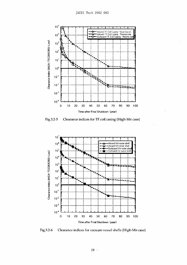
3.2.2 High-Mn Case
Clearance indices in High-M~n case are shown in Figs.3.2-5 to 3.2-8. In this case
IAEA-TECDOC-855-Low values are applied to the assessments of clearance potential.
Clearance indices of the TF coil casing are shown in Fig.3.2-5. The indices are given
for 3 positions of two inboard and one outboard coil casing points. For inboard coil
casing (see Fig.2.1-2), the nose region reaches to the clearance level at around 30
years after final shutdown, but the surface of plasma side can not reach to the
clearance level within 100 years after shutdown. For the plasma side surface of the
outboard coil case, about 25 years are necessary to reach to the clearance level.
Figure 3.2-6 shows the clearance indices of the vacuum vessel shells. Specific
activities at the surface of the shells are assessed for the clearance potential. For inner
shell of the vacuum vessel the clearance indices cannot show the clearance level up
to 100 years after final shutdown. The inboard outer shell also remains above the
clearance level beyond 100 years. However, the outer shell of the outboard vacuum
vessel has clearance potential at about 30 years after final shutdown.
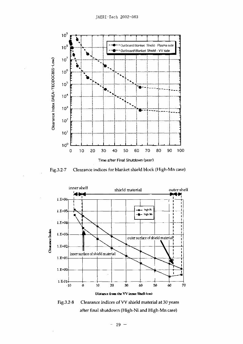
Figure 3.2-7 shows the clearance indices of the blanket shield block. These
components remain above clearance level beyond 100 years. Figure 3.2-8 shows
also the clearance index of the vacuum vessel shield material at 30 years after final
shutdown for High-Mn case as well as the High-Ni case. For High-Mn case, small
area near the rear shield material will reach to the clearance level. The clearance
index for High-Mn case is one order of magnitude below the High-Ni case.
.At the ITER decommissioning point of view, there are 8 isotopes that are relevant
with regard to clearance up to 100 years after final shutdown. These isotopes are3 H1, 14C, 54Mn , 55Fe, 60CO, 63Ni, 'Nb and 99Tc. Up to 60 years after final shutdown, the
clearance indices are dominated b y 6 Co. Beyond about 60 years, 14 Nb becomes a
dominant isotope. Detailed analysis results are presented in Appendix-2.
Comparison of the clearance potentials between High-Ni and High-M~n cases is
summarized in Table3.2-1. High-Mn case has a potential benefit for the clearance
possibility of the outboard TF coil casing. Around 3,000 tonnes of the radwastes are
reduced in the High-Mn case at 30- 40 years after final shutdown. Details are
discussed in section 5.
-22 -

JAERI-Tech 2002-083
Ln >Ln a,
> C� c en e M n en cn Cn cn cn en e M cn en< 0 0 0 c c 0 0 0 c c c'4�' m cn 6 en M d rn - . . . . . . . . cj en
Ln
ui
al 0 (0 N N (m N 1* CO CO CO0 0 o - m N m . . . 0 0 G J 0 -can 0 CS Ln 0 0 0 0 0 0 c; 0
Ln a) m Ln m- Ln CO cnca m (n cnm2 7 7 7 -0 n 0 -r A- -r-
Q 0 cn0 en C 0 cn 0 C) Cl cn 0 (D (n 0 (V)CY CS 6 0 Q o 0 c) 6 en cnc CD 0 cf)M cn Cf) (f)
_i0 0 c 0 C Ln C) 0a 0 0 0 (M o C Ln CV) 0C> 0 o (0 Tr
C' o ri C) .. 0 't 0 0 0 CSN 00
N 1* L, W Ln L, 0) r- ooo Ln 0) CD a)nt N cnen N N (n cn m Ln Ln Ln Ln LnW0 (b ch CL m 1� 1 4 6 6 68 z z U 2 LL u~ U U z N U)
23

JAERI-Tech 2002-083
CU ~~c jcc;cUc
2 2~~~~~~~~azz22 CJ~~~~~~~~~~ C~~CJc c
FE2
CB C
U.) ~~~cj C Z- Z_ Z Z c A
ez c C C.) U cu c eU
CU ~~~~~~~~~~~~~~~~~~~~~~CU C~~~0
-~~~~~~~~~ 00 00 c11T UC 0Z 2z2 z z z z z z
U.) z z z -C
-~~~~~~~~ CU~~~~~~~~~~~~c C
0.) CU CU n~~~~~ CU CUC
m ) E 2 CU CU 0 Um ) U - 50CU 0'L
0 U tt .-- 4c c 0 . 0 W 3 -r U CU
U cj U ) U
U() ~ w U-~ UCUCCUC24

JAERI-Tech 2002-083
100 1 T
0
>
0w
H-3 C-14 Mn-54 Fe-55 Co.60 Ni63 Nb-94 Tc-99
Major Radionuclides
Fig.3.1 -1 Comparison of clearance level between TECDOC-855-Average
and TECC-855-Low
- 25

JAERI-Tech 2002-083
- - - - - - -~- E-igh-N ra-inboard
11+03 ~~~~~~~~~~~~-Hig-Nirot-outr a
1E+01 __
.E-02_ _ _ _ __ _
E-0…
0 10 20 30 40 -50 60 70 80 90 100
Time after Final Shutdown (year)
Fig.2-1 Clearance indices for covsl cshel (current design; High-Ni case)
1.11+07~- 26

JAERI-Tech 2002-083
1.E+09
1E+08
1.E+07HiNrerutod
1.E+06
1.E+05.
L.E+04
L.E+02,__
11.+s01 Blanket shield blocks are categorized into radwastesfor both dlearance index (TECDOC-855-Average and TECDO(>855-Low)
1.E+0O a io 20 30 40 50 60 70 80 90 100
Time after Shutdown (year)
Fig.3.2-3 Clearance indices for blanket shield block
(current design; High-Ni case)
inner shell shield material outer shell
1.E±06,
L E+04.
1.E+03~
E+2innersurfaceofshield material ___11+01 -~ ~ ~ ~ ~ ~ 1 -
11E+couter su rface of shield materia
1.E-al I-10 0 10 20 30 40 50 60 70
Distance fromn the VV inner Sheli (cm)
Fig.3.2-4 Clearance index of outboard VV shield material
at 30 years after final shutdown (current design; High-Ni case)
- 27 -
JAERI-Tech 2002-083
10 A
I -~~~~~ l~~nbcnr1 T Ci Casing Nose regionio4 .. -a--.... ...... .. Inboard F: Coi Casing -Piasma side4 0 ~~~~~Outboard TF Coil Casing Plasma sid
i 3
00 2
o '
1 01 k ~ .C
10 102 040tt6 0 09 0
1 Ut¶7
10 % *,
i 3
10 1 J ± J i JL....J......L.....L................................ ...........
C 10T1 ~~~~6 Inboard VV outer shell~~~~~~~~~~~~~~~~~~~~
tttfttq-4-
Timeafte Finl Sh-A-w -(Inbar)Vine hl
Fig.12-6 Cearance idices forv-cu @m-vuteloardVl irghl cse
- 28- U I --
JAERI-Tech 2002-083
8 Outboard blanket Sh eld Plasma aside1 0 ..... ..... ......
Outboard Blnt Shield side
7 ~ -I
00od 1 0
w ) . . . . .. . . . .. . . . .. . . . .. . . .. . .. . . . .. . . .. .. . . . .. . . . .. .
100.
0 03 4 06 0)09 0
_ 10~~~~Tm ftrFia hudw.(er
Fi1) - laac nie o lne hedbok(ihM ae
ine hl hedmtra ue hlC~~~~ -~~ ic~FiI.E
LE1) .
LE0
100 10 20 30 40 50 60 7080 9 10
imne afterFhnal ShudneShl (ea)
Fig.2-8 Clearance indcs o blne shield blocka a (HghM ease
i anrtselia hudw HihN n shieldM outerhl
~~4 ~ ~ ~ 29

JAERI-Tech 2002-083
4. Activation Level of Radwaste
Actual quantity or concentration limits on classification of the radwastes will be
established by the regulatory body of the host country. In this section the
categories of the major tokamak components (TF` coil casing, vacuum vessel, blanket)
are investigated on the basis of the classification of the radwastes for its safe disposal
in Japan.
4.1 Classification of Radwaste
In Japan, radioactive solid wastes are classified into two levels for regulatory
purpose. At present, categories of 'High-level' and 'Low-level' are defined for the
radioactive wastes. The high-level radwaste is defined as the highly radioactive
material resulting from the reprocessing of spent fuel, including liquid waste
produced during reprocessing and solid materials derived from such liquid waste.
Subsequently, the low-level radwaste in Japan is categorized into 3 classes (Li: high-
beta and gamma waste, L2: low-level waste, L3 : extremely low-level waste) given in
Appendix-3. In accordance with the radwaste classes, appropriate approach for
final disposal is taken into account.
Representative values of the activity concentration for the radwaste category are
summarized in the following table;
[Classification of solid radwaste (Bq/ton)I [41L1 waste (high-beta, gamma) L2 waste (low-level) L3 waste (extremely low-level)
H-3: C > 150P** H-3: 3.OG* <• C < 5OP** H-3: C < 3.OG *
C-14: C >37G* C-14: II1OM*•<C< 37G* C-14: C < 1M*K-40: CŽ> 170M** Ca-41: 5OM* <•C < 3.1 G* Ca-4 1: C < 150M*Ca-41: C Ž 3.1G* Co-60: 8.1G* < C < II .LT Co-60: C < 8.1G*
Co-60: C> Ž I. IT* Ni-63: 7.2G* < C < . IT* Ni-63: C < 7.2G*Ni-63: C > 1. 1 IT* Sr-90: 4.7M * < C < 74G * Sr-90: C < 4.7M*Sr-90: C > 74G* Nb-94: 8M** < C < I IG** Nb-94: C < ISM* *
Nb-94: C 1 G** Tc-99: 9.OM** < C < 190M** Tc-99: C < 9.OM**Tc-99: C>190M** Cs-137: l00OM* 5C <1.llIT* Cs-137: C <l00M*Cs-137: C Ž: .IIT* Eu- 152: C < 360M* Eu-152: C < 360M*Eu-I152: C Ž 360M* an alpha emitter: C < 1. 11 G* an alpha emitter: C < I17M*
an alpha emitter: < 1.ll G*[Notes]
A value with a single star-mark ()is quoted from the Article 13-9 of the government cabinet No. 324 for "thelaw for regulation of nuclear source material, nuclear fuel material and reactors".
A value with a double star-mark (**) is not enacted yet, but it is used in the examination of safety approaches forradwaste disposal that the government has held.
4.2 Categorization of Radwaste
Activation levels of TF coil casing, vacuum vessel shell and blanket shield were
investigated on the basis of the above radwaste classification. Results of the
activation calculation for High-Ni and High-Mn cases are assessed in this section.
- 30 -

JAERI-Tech 2002-083
4.2.1 High-Ni Case (current design)
In ITER it is noted that there is no "High-Level" radwastes due mainly to low
neutron fluence (-0.3 MWa/m2 ), so that the assessment is concentrated to provide
the major tokamak components to be categorized into which classes. In accordance
with the classification of radwaste level, L2 and L3 limit indices for TF coil casing,
vacuum vessel and blanket shield block are shown in Fig.4.2-1 and Fig.4.2-2,
respectively. TF coil casing is categorized into L3 at 30-40 years after final
shutdown. For vacuum vessel shells, the outer walls of inboard and outboard
regions fall into L3 after 30-40 years. The inner walls of the vacuum vessel shells
will reach to the L2 limit at 30-40 years after final shutdown, but marginal. If the
neutron streaming between the adjacent blanket module gaps were relatively high,
the inner walls will be categorized into Li. For blanket shield the front (plasma
side) surface is categorized into Li and the rear one is categorized into L2.
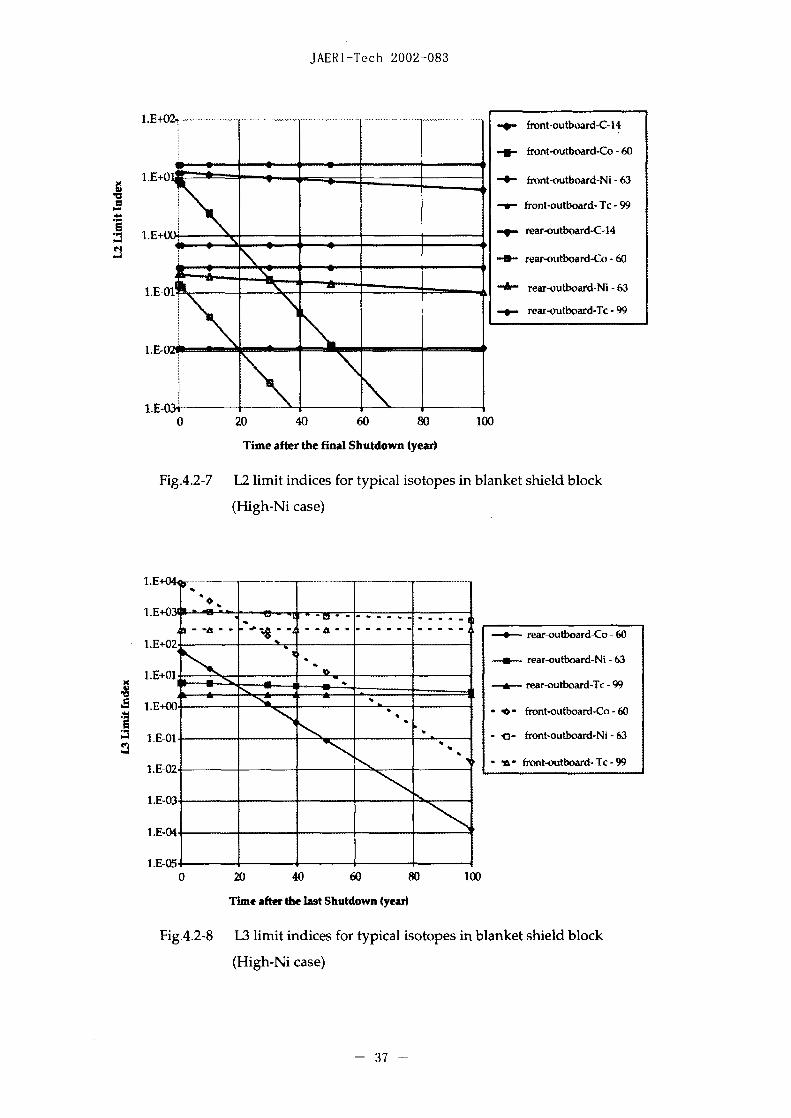
Limit indices of major isotopes are shown in Figs.4.2-3 to 4.2-8. Technetium-99
dominates the L2 limit indices for each component at 30 - 40 years after final
shutdown. On the other hand, the L3 limit indices are dominated by 60Co up to
about 20 years, and by `3Ni and ' 9Tc beyond about 20 years after final shutdown,
respectively. According to these analysis results, reducing Ni, Co and Mo contents
in the steel appears to be effective for reducing the activation level. The L3 limit
index of vacuum vessel shield material (outboard region) at 30 years after final
shutdown is shown in Fig.4.2-9. Taking account into the summation of the L3 limit
indices of each isotope, material within 20mm in depth from outboard inner shell is
categorized into L2. Subsequently, approximately 2/3 of the outboard shield
material will be categorized into L3. For inboard shield material all region will be
categorized into L2 since the thickness of the inboard shield material is as small as
217mm (cf. 630mm for outboard).
4.2.2 High-Mn Case
L2 and L3 Limit indices for High-Mn case are shown in Fig.4.2-10 and Fig.4.2-11.
For TF coil casing, both of inboard and outboard casings are categorized into L3 with
a sufficient margin at final shutdown. The inner shells of the vacuum vessel are
categorized into L2. A magnitude of margin for L2 limit is maintained in the High-
Mn case. Induced activities in the outer shells of the vacuum vessel are well below
the L3 limit at final shutdown. The near surface of the blanket shield block cannot
reach to the L2 limit during 100 years after final shutdown. The activity at rear
surface of a blanket meets the L2 limit at final shutdown. It is noted that the
- 31 -

JAERI-Tech 2002-083
activities of the separable first wall materials such as beryllium, copper-alloy and
small amount of stainless steel are not assessed in this study because of regularly
exchange parts. Main isotopes that contribute to L2 and L3 limit index are as
follows;
[For L2 limit index] [For L3 limit index]
TF coil casing ` 3Ni, 4̀C TF coil casing : 6̀ Ni, `4C
VV shell : 63Ni, 99Tc VV shell : 63Ni, 14c
Blanket shield: 14C, 63Ni Blanket shield : H, 14C
Details are presented in Appendix-4.
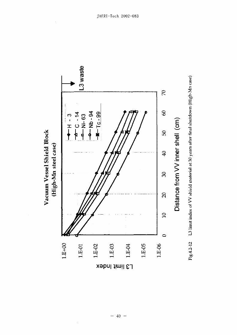
For the shield material of the outboard vacuum vessel, L3 limit index at 30 years
after final shutdown is shown in Fig.4.2-12. Taking into account for the summation
of the L3 limit indices of each isotope, about 10mm depth from outboard inner shell
is categorized into L2. Approximately 1/6 of the outboard shield material is
categorized into L3. It also shows that 1/2 of inboard shield material is categorized
into L3.
Table4.2-1 shows the summary of the categorization of the components for High-
Ni and High-Mn cases at 40 years after final shutdown. It is clear that the High-Mn
case has advantages for reducing activation levels with regard to rear region of
blanket shield, VV inner shell, VV shield material and outboard TF coil casing,
resulting in easier decommissioning process.
- 32-

JAERI-Tech 2002-083
Table4.2-1 ITER radwaste classes for high-Ni and high-Mn steels at 40
years cooling
Component Region Radwaste Classes
High-Ni Steel High-Mn-Steel
Blanket Inboard front/rear Li/Li L1IL2
outboard front/rear MLL Ll/L2
Vacuum Inboard inner shell Li L2Vessel
Inboard shield block L2 L2/L3 *11
Inboard outer shell 1,3 L3
Outboard inner shell Li L2
Outboard shield L2/L3 *21 L2/L3 [*3]block
Outboard outer shell L3 L3
TF coil case inboard L3 L3
outboard L3 < Clearance level
[Notes]
*Clearance: Low value of IAEA-TECDOC-855
*11 In the High-Mn case -1/2 of inboard shield block will be classified into L,3 radwaste.
*1 In the High-Ni case -1/3 of outboard shield block will be classified into L,2 radwaste.
*[*3] In the High-Mn case -'-1 /6 of outboard shield block will be classified into L2 radwaste.
-33 -

JAERI-Tech 2002-083
L.E+0.
- Moil case-inboardI.E 00 ________ -~~~~~~~ -~~- VVI-rear-inboard
I ________ ~~~~~-*eW- lanket-front-outboard
-0-- lnanket-rear-outboard.C lEM U Vfront-outboard
-B- VV-rear-outboard~2 .E-02. -- TFeoil ~aeoutboard
L.E-04._ _ _ _
I.E-052 -
1.E5-O(0 20 40 60 W5 100
Time after Final Shutdown (year)
Fig.4.2-1 L2 limit index for major tokamnak components
(High-Ni case)
L.E+05.
-~~ _______ - .... ~~TFeoil caswe-inboard1.E±03 - 6- - VV~~~~~~~~~~~-rear-inboard
x 11+02 ~ ~ ~ ~ ~ ~ ~ ~ ~ ~ ~ ~~~~- Blanket-front-outboard1.E+02 --- ~~~~~~~~~~~~~~~ Blanket-rear-outboard
-- VVfront-outboard*~1.+01 -a- V-riear-outboard.
T~co case-outboardI .E+00i~.
1.E-02 ._ _ _ _
1.E-03 _ _ _ _ _ _ _ _
l.E-04.o 20 40 60 80 100
Time after the last Shutdown (year)
Fig.4.2-2 13 limit index for major tokamnak components
(High-Ni case)
- 34 -

JAERI-Tech 2002-083
I .- 02
L.E-03 1
*-.-.~~ C-14-inboard
*.U--~~~.. ..... ..... _. CO -60-inboard
1.E-05 -a.NI -6-inboard
TC -99-inboard
1.11E-06 --- C - 14-outboardC4
-U--CO - 60-outboard1.1E-07
~-NI - 63-outboard
L E-0S___ ___ ___ - TC - 99-outboard
L E-09
1.1E-100 20 40 60 s0 100
Time after the final Shutdown (year)
Fig.4.2-3 L2 limit indices for typical isotopes in TF coil casing
(High-Ni case)
.100
1.E-02 ____... CO-60-inboard
-. ~.NI -63-inboard
CO -60-outboardI .E414 - - .-.u-- ~~~~~~~~~~NI - 63-outboard
--- TC -99-outboard11.-05
11E-06.
1.E-07
Time after the last Shutdown (year)
Fig.4.2-4 [3 limit indices for typical isotopes in TF coil casing
(High-Ni case)
- 35 -

JAERI-Tech 2002-083
______ - -- - rar-inboard-C-14
L.E-01 _____ -- rear-inboiard-Co -60
* A-rear-inboard-Ni -63
*..rear-inboard-Ic -99
~~ 1.E-03 -. ~~~~. ............ _. .... . front-outboard-C-14
f.~ ront-outboard-Co - 60
L 1E-04 h- .. .
front-outboard-Ni -63
1.E-05 - front-outboard- Tc -99
'cl r#~~~~~. ar-outboard-C- 1 4
--- rear-outboard-Co - 60
07 ~ ~ ~ ~ ~ ~ ____ a-rear-ob-Ni - 63
--- rear-o-ilc -991 E -0 8.................. ........... .... ..
0 20 40 60 so 100
Time after Final Shutdown (year)
Fig.4.2-5 L2 limit indices for typical isotopes in VV shells
(High-Ni case)
- -rear-inboard-Co -60
LE+00;h.. ~ ~ ~ ~ ~ ~ ~ ~~~~~~~--a--rear-inboard-Ni -63
i.E-Oi - ~~~~~~~~~~~~~~~~- rear-inboard-Tc -99
A **.-*....... rear-outboard-Co -60
41, a. rear-outboard-Ni -63
--- A&- rear-outboard-Tc-99
LE-041M a ~ ~ ~ ~ ~ ~ ~ ~~~~~~- fronit-outbo,,ard-Co -60
________ ________ -~~~~~~~i arnt-outboard-Ni -63
.- front-outboard- Tc -99
0 20 40 60 s0 100
Time after the last Shutdown (year)
Fig.4.2-6 L3 limit indices for typical isotopes in VV shells
(High-Ni case)
- 36 -
JAERI-Tech 2002-083
1.E-i-02. -- ~~~~~~~~~~~~front-outboard-C-14
-- front-outboard-Co -60
L E+( front-outboard-Ni -63
-w- front-outboard- Tc -99
-~rear-outboard-C-14
-*- rear-outboard-Co -60
_________ _________ 4- rear-outboard-Ni -63
rear-outboard-Tc -99
0 20 40 60 80 100
Time after the final Shutdown (year)
Fig.4.2-7 L2 limit indices for typical isotopes in blanket shield block
(High-Ni case)
- - - 4--4'---~~~~~~~~~~ rear-outboard-Co -60
I.E 1. - -.--- rear-outboard-Ni -63
1.E4-0] -a- ~~~~~~~~~~~~~~~rear-outboard-Tc -99
LE*00 fotoutboard-Co -60
11 -Ol -c-~ - front-outboard-Ni -63
1 .1-02 _ ___ -A- front-outboard- Tc -99
1,E-03.
11.-04.
L E-05 ____
o 20 40 60 80 100
Time after the last Shutdown (year)
Fig.4.2-8 1,3 limit indices for typical isotopes in blanket shield block
(High-Ni case)
- 37 -

JAERI-Tech 2002-083
CO
C")~~~~~~~c
C:)~~~~C
U~~~~~~~~~~~~~~~~
C) C) C? C?~~~~~0 C
38 -~ ~ ~ ~ -

JAERI-Tech 2002-083
- * l nboard-TF coil case -front-ClD - - nboard-VV outer shell -front
-- l nboard-VV inner shell -front10 I ~Outoard BLsheld fro t
Outboard-BL shield earWOuboard- i'~nner shel -f ont
10 ......................- - Outoc~rd Vo ter shel froa-0 Outboard-TF coil case front
0
1 01
10-
(N 0 ......
1 06
1 0
0 1 0 20 30 40 50 60 70 80 90 100
Time after Final Shutdown (year)
Fig.4.2-10 12 limit indices for TF coil casing, VV shell and blanket shield block
::*:lnbo ard-TF coil case -front--0 - nboard-VV outer shell -front
E- -lnboard-VV inner shell -front'I5 _______O____]~ utboard-BL shield -front
10.~~~~~~- Outboard-BL shield -rear-~0utboadVV inner shell front
1 ~~~~~~~~~-)Outbcaid-VV outer shel front
10O
E 10 -
-j 1
.m.. .. .…
-3
-4
1 0-
0 20 40 60 80 100
Time after Final Shutdown (year)
Fig.4.2-11 L3 limit indices for TF coil casing, VV shell and blanket shield block
- 39 -
JAERI-Tech 2002-083
U)~~~~~~~~~~~~~U
C) () Q) C
Co II! iiC-
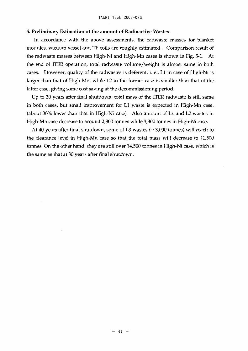
- -- - 0) - 40
JAERI-Tech 2002-083
5. Preliminary Estimation of the amount of Radioactive Wastes
In accordance with the above assessments, the radwaste masses for blanket
modules, vacuum vessel and TF coils are roughly estimated. Comparison result of
the radwaste masses between High-Ni and High-Mn cases is shown in Fig. 5-1. At
the end of ITER operation, total radwaste volume/weight is almost same in both
cases. However, quality of the radwastes is deferent, i. e., Li in case of High-N is
larger than that of High-Mn, while L2 in the former case is smaller than that of the
latter case, giving some cost saving at the decommissioning period.
Up to 30 years after final shutdown, total mass of the ITER radwaste is still same
in both cases, but small improvement for Li waste is expected in High-Mn case.
(about 300/ lower than that in High-Ni case) Also amount of Li and L2 wastes in
High-Mn case decrease to around 2,800 tonines while 3,300 tonnes in High-Ni case.
At 40 years after final shutdown, some of L3 wastes ( 3,000 tonnes) will reach to
the clearance level in High-Mn case so that the total mass will decrease to 11,500
tonnes. On the other hand, they are still over 14,500 tonnes in High-Ni case, which is
the same as that at 30 years after final shutdown.
-41 -
JAERI-Tech 2002-083
0113 (extremely low-level)
1 .6E+04 a__ _ _ _ _ _ _ _ _ _ _ _ _ _ _ *L2 (low-level)ELi (high-beta, gamma)
1 .4E+04
1. 2E+040
1.0E+04
8.O1E+03
6.OE±03
4.0E+03
2.0E+03
0.OE+00at final shutdown 30 years 40 years
Time after final shutdown (year)
a) Current Design (High-Ni steel case)
1 .6E+04 __ _ _ _ _ _ _ _ _ _ _ _ _ _ _ _ _ _ _ 013 (extremely low-level)a*L2 (low-level)ELI (high-beta gamma)
1.4E+04
1.21E+04
lj 1.OE+04 .~.
8.OE+03
4- 6.OE+03 --- ~ -
0
4.OE+03
0.0E+00at final shutdown 30 years 40 years
Time after final shutdown (year)
b) High-Mn steel case
Fig.5-1 Remaining radwaste masses after final shutdown for blanket,
vacuum vessel and TF coil
- 42 -

JAERI-Tech 2002-083
6. Conclusions
Employing less Ni and Co steel in place of high Ni austenitic steel for blanket
shield block, vacuum vessel shield material and TF coil casing has been studied as
one of the effective ways to reduce the activated materials at the decommissioning
phase. Idea for material changes is to play roles of reducing the radioactive wastes
and its radiation level for TF coil casing and of reducing activation levels for the
shield blocks. Based on the systematic analysis, assessment of the activation level
and brief radwaste mass estimates are performed. It believes that reduction of
amount of the radioactive wastes gives effective cost saving at the decommissioning
period. Major results are as follows;
1) The outboard TF coil casing for High-Mn case has the clearance potential at 30
to 40 years after final shutdown while it will be practically difficult for High-Ni
case.
2) Compared to High-Ni case, additional 3,000 tonnes of the radioactive wastes
will be moved to clearance for High-Mn case at 30 to 40 years after final
shutdown.
3) The inner shells of the vacuum vessel are categorized into L2 (low-level) for
High-Mn case in accordance with current Japanese regulation, but on the other
hand the shells for High-Ni case remain in the Li (high-beta, gamma) at 30 to
40 years after final shutdown.
To apply this concept to the ITER project, it is necessary to provide further
evaluations such as the material applicability, fabricability, compatibility with the
related components and acquisition. In particular the fabricability for magnet
structure, the weldability is the most important issue so that R&D study is
intensively ongoing as a part of demonstration of fabricability for ITER CS jacket
material. For change of shield material, it will be less problem because of no
structural components and simple structure.
-43 -

JAERI-Tech 2002-083
Acknowledgements
The authors would like to express their gratitude to Dr. . Shoji, member of
Department of ITER Project and Drs. H. ida, J. Reader of ITER International Team
for their valuable discussions and comments. They also would acknowledge Drs. T.
Tsunematsu, T. Takatsu, M. Seki, S. Matsuda and Dr. H. Kishimoto for their support
and encouragement.
References[1] Generic Site Safety Report (GSSR), Volume V, "Radioactive Materials,
Decommissioning and Waste", G84 RI 4 01-07-06 R 1.0, 2001.
[2] Y.Seki, H.Iida, H.Kawasaki and K.Yamada, THIDA-2: An Advanced Code Systemfor Calculation of Transmutation, Activation, Decay Heat and Dose Rate, JAERI1301, March 1986.
[3] "Clearance Level for Radionuclides in Solid Materials", International AtomicEnergy Agency, IAEA-TECDOC-855, Vienna, 1996.
[4] Classification of radwaste for its safe disposal in Japan, November 24, 2001.
-44 -
JAERI-Tech 2002-083
Appendix-i
Specific activities of TF coil casing, vacuum vessel and blanket
- 45 -

This is a blank page.

JAERI-Tcch 2002-083
Analysis cross section
Vacuum Vessel ~~~~~Vacuum Vessel
Shi el ding Bl anket Shielding Blanket 41 1617
Inboard Region Materas . .Outboard RegionSurface of CS coil c ace CS Coil 12 Bl anke s hiel d - 1
2 TF coil case - 1 Structual material: 55316WN3 - ~~~~~~~~~~~~~~Conductor Nb3Sn 13 Blanket shiecld - 2
iT coil case 2 *T~~~~~~-F Coil 14 VVinner wall - 14 IF col case - 3 Structual materi al: JK2 1 5 VVinner wall - 25 TF coilI case - 4 _conductor Nb3Sn 16 Voue al
6 VV outer wall - 1 ~~~~~~.Vacuum Vessel 16____ wi 6 W outer W all - 1 -Structual material: SS316LN 17 VVouter w al I- 2
7 VV outer w all -2 _Shield material : SS204L- 18 TF coil case - 1
8 VV inner wall 1- -Shielding Blanket 19 IF coil case - 29 VV inner wall -2 FW e/Cu/SS316LN
10 Blanet shicl cl 1 _~Shie Ldmaterial : JK2 20 IF coil case - 310 Blanket shield - 1 ~~~~~Tlrmal Shield 21 IF coil cas - 4
11131Blanket s hiecldc - 2 Structual material : SS3161LNSurface coating: Ag
Analysis points
-47
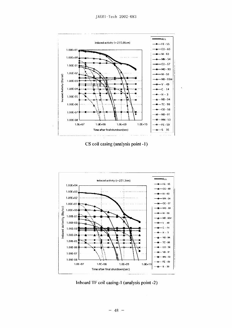
JAERIVTech 2002-083
-ALLinduced activity (r-21 5.66cm) -.-- FE -55
1 .OOE+01 -- CO -60
NI-63
1.OOE+00 - -- -- ----- -4- MN -54
1.OOE-01 ~ ~ ~ ~ ~ ~ ~ ~ 4*CO -57
MO-93
1.0OE-02 .......... NI ~~~- 59
& B- 93m1.OOE-03 ... --.
-U4&-V -49
1.GOE-04 -- ....- 4' - £ - -4- C -14
1.OOE-05
1.001E06 ... .. .. m ...TC -99
1.OOE-07 91K~----
1.OE+07 1.OE+08 1.OE+09 1.OE+10 ---O --- FE -59
Time after final shutdown(sec) - A--- -35
CS coil casing (analysis point - )
induced activity (r=221 .3cm) - L1.OOE+04 *~~~~~~~~~~~.---FE 65
-A-CO -60
-- NI -63
1.OOE+0 --------- - ------ -4- MN -54
1.00E4-01- --------- e - 57IN-MO 93
-O-NI 59
~~, 1.OOE-O1 - -A--~~~~~~~~~~~~&Ne - 93m
b.CE-0 1-- U-V -49
-- C -14
o --4--~~~~~~~~~~~~~~~~~~H - 31 .OOE-04 ------ A-A
--A-NB -94
lOCE-OS ------ -- -----
1 .OOE-06, ---X-'.-X ---- --x - ---- x rx -4-CO -58
--- X- NB -91
--- X- MN -53
G-FE -591.1DE+07 1.OE±08 1.OE+09 1.OE 1 0
---h--S -35Time after final shutdown(sec) -
Inboard TF coil casing-I1 (analysis point -2)
48 -
JAERI-Tech 2002-083
-ALL2induced activity (r=240.99cm) -.- FE -55
1.13OE+06 ~ ~ ~ ~ ~ ~ ~ -ACO -c0
1.0011+04' 5 ~~~~~~~4-MN -54
1.001E+03 ........ )q CO ~~~~~~~- 57
1.OOE+02 M MO~~~~~~~~~~~~~~~-93
g1.OOIE±O1 *--- -0-NI -59
31 1.OOE-i-O - -- NB -93m
1.0OE-01 R V ~~~~~~~~~~~~~~~~~~~~~- 49
1.OOE-02 0 ~~~~~~~~4-C -14
U 1OO0E-03 --- H - 3
----IE04 ----- - -A -- B -9
1.IOOE-05 ---- -.- - -T -9
1.00IE-06 ~ ~ ~ ~ ~ ~ ~ ~ -4-CO -
100OE-07 ---X-NB 9
1 .OOE-08 ~~~~~~~~~~~~~~~--- X- MIN-53
1.OE+07 LIDE+08 1O0E+09 LOE+10 FE -59
Time after final shutdown(sec) --- -- - 3-5
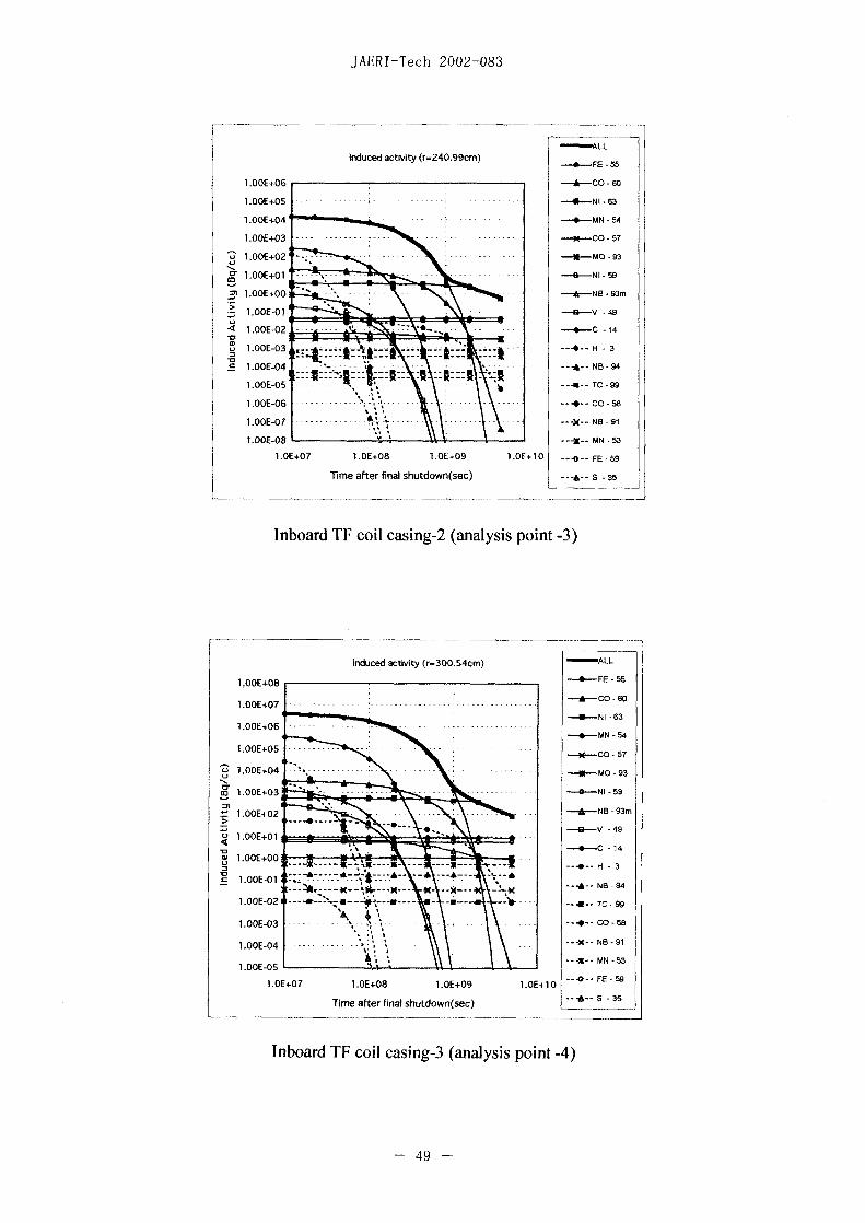
Inboard TF coil casing-2 (analysis point -3)
induced activity (r-300.54cm) -ALL
__ __ _ __ __ _ __ __ _ __ __ _ __ __ _ __ __ 4- - F E -55
-ACO -860
-- NI 863
-4-MN -54
-% CO 57
Z1.OODE+04 ---
1.OOE+02 ib ~~~~~~~~-ANB -93m
-B--V -49U1.OO1E+01
-- C 14o1.OOE+OO
1.OODE-03 - CO -
1.OOE-04 1 ---------- X- NB -91
1 .OOE-OS ---IN-~~~~~~~~~~~~~~~- MN -53
1O0E+07 1.OE+08 LO0E+09 1OE+1O --- 0- FE-SB9
Time after final shutdown(sec) -35_
Inboard TF coil casing-3 (analysis point -4)
- 49 -

JAERI-Tech 2002-083
induced activity (r=306.96cm)-- FE-5
LOOE+08 CO ~~~~~~~~~~~~~~~~- 60
- -- -- ----- ~~~-U-i- NI -63
LOOE+06 ~ ~ ~~~~~~~~--MN -54
CO-57
--MO -933 1OOE+04 ~.--N 5
L OOE+03 --- ---NB -93m
1.00E+02 *" -- --- --- V -49
. - 14
~~ 1.OOE+0O ~ ~ ~~~A __ ---- - H - 3
)1 .OOE-00 -- ~~- os
--- -- NB- 94
LOIDE-03indued- ctiit------cm -- ---X NB-9
LOOE-04 -------- VI~~~~----- N 54
LOE02 FE -
- --------- -------- m--
1.OOE-02 - - iduedac -ty r32-Om-- AL---
LOIDE+05 --------- ............ X--NB-9
L.0DE-04 --- .... .. ------------ --- CO - - -57
m NI ~~~~~~~~~~~~~~~-- --- 59
1.1 +7 10+6 10+9 LE+02-A-S3Time after final shutdown~~~~~~~scNB- 93m
1.O1I"oar VVouerwllIVaalsi oit96
- 50 -~~~~~~~~~~~0 C 1
JAERI Tech 2002-083
-ALLinduced activity (r=329.Ocm)
--4--FE- 55
1.OOE+07 ~ ~ ~ ~ ~ ~ ~ ~ ~ -*-CO 60
1.OOE+06 ~ ~ ~ ~ ~ ~ ~ ~ ~ -- NI 63
-4-MN -54
CO-57
1.00E+04 M MO ~~~~~~~~~~~~~~- 93
1. *-40-NI 59
1.OOE+02 ~ ~ ~ ~ ~ ~ ~ ~ ~ -A-NB 93m
-U9--V -49
1.OOE+01U -4-C -14
--- HC-3
1.0011-01 ~~~~~~~~~~~~--AX- NB- 94
1O0OE-02 ---i---N-5
---- NB- 91
L.OE+07 1.OE+08 1.OE+09 1.0E-.10 --- &--S -35
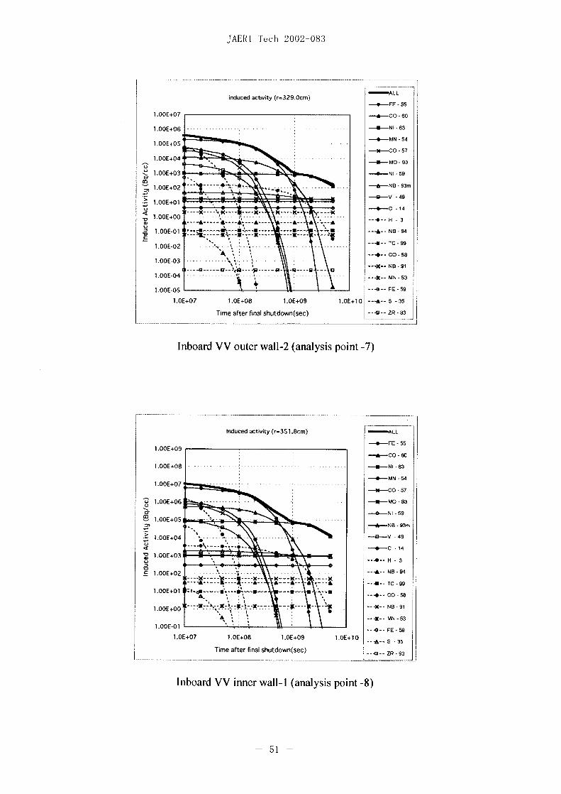
Time after final shutdown(sec) --- ZR -93
Inboard VV outer wall-2 (analysis point -7)
Induced activity (r=35 1.8cm) -ALL
0 E- 55
-60
-4-MN -54
-- CO -57
Z1.OOE+06 .... MO-9
N-59
ONB- 93m
> 0 ~~~~~~~~~~~~~~i-V -49
-14
cj .~~~~~~~~~~~~~~~~-4 -- H -3
--A- - NB -94
1OO0E+0 2m.. g-m - --- - *-
1.OOE+OO.-.-i-- MN -53
1.OOE-O1 0-- FE -59
LIDE±07 LOE+08 1OE1+09 1.OE+10 -- 3
Time after final shutdlown(sec) ---4a ZR -93
Inboard VV inner wall- (analysis point -8)
51

JAERI-Tech 2002-083
-ALLinduced activity (r=356.8cm)
E- 55
1.00IE+09 ~ ~ ~ ~ ~ ~ -ACO - 0
- -63
--MN -54
1.01DE+07 ~ ~ ~ ~ ~ ~ ~ -NCO- 57
-1.OO1E+0 -- MO -93
-Q-NI -59
1.001E+05 ~~~~~~~~~~~~-f-NB -93m
-- V -49
z 1.OOE+04 ~~~~~~~~~~~~~ -0C 14
-4 DE0 7 4
1OODE+0;X
1.OOE-i-01 - - ~~-M--------- 4;-
---- NB- 91
---E--MN -53
1 .OOE-O1 ~~~~~~~~~~~~~~~~~-- FE -59
1.O1E+07 1.OE+08 1O0E+09 1.OE+10 -- -A-- -35
Time after final shutdown(sec) -- ZR -93
Inboard VV inner wall-2 (analysis point -9)
-ALLinduced activity (r=365.3cm)
-- .- -55
1.OOE+1 1 - -CO - 0
l O- 57
o -*--~~~~~~~~~~~~~~~~~~~~MO -93
-f---NI 59
,1.OO1E+05 ------ --f- -NB- 49
-4~~~~~~~~~~~~~~~~~~~~~~
1.00EA3 --------- ~ ~ ~ ~ ~ -4- C -S
1OO0E+OO--
1.00EA0 ----- -...-- N- 1
1 .OOE-01 -- X N-5
1.OE+07 1.OE+08 LOE+09 LOE+10 --- - E -59
Time after final shutdown(sec) ---&--S 35
Inboard blanket shield-I1 (analysis point - 10)
- 52 -
JAERI-Tech 2002-083
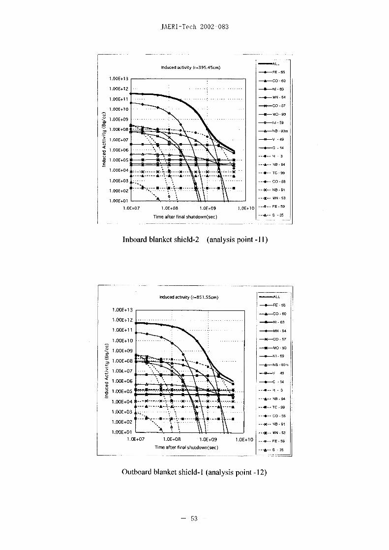
induced activity (r=395.45cm) - L-- E- 55
1.OOE+ 1 3 ~ ~ ~ ~ ~ ~ ~ ~ --- CO 60
1.00E+12 ~ ~ ~ ~ ~ ~ ~~~~~--N -63
-4-MN 54
--- CO -57
---MO 93
0 E -4--NI---59
11.OOE+013 -- NB 93m
> --- Q~~~~~~~~~~~~~~~~~~~~~~~~~~- 49
.g1.OOE+05C ---~~~~~~~~~~~~~~~~~~~~A- NB 94
1.OOE+04 ..;(- X-- 9 -4- TC -99
1.00E+03 ~ ~ ~ ~ ~ ~ ~~~~~--- CO -
1.00EA1 ~ ~ ~ ~ ~ ~ ~~~~~~--I-MN -53
1.O1E±07 1.OE+08 1.OE+09 1.OE1+1O0 - FE 59
Time after final shutdown(sec) .. ---- S -35
Inboard blanket shield-2 (analysis point -Il)
induced activity (r-85 1.55cm) --- L
-----h-FE 55VOO1E+1 3
-- CO -60
1.OOE+1 2 --- - ---- N 63
1.OO -11-- -.-........ ---4--MN -54
Li -E---~~~~~~~~~~~~MO 93'f1.OOE-409-
~~, 1OOE+08 -- -- - ~~~~~~~~~~~-0--N I 59
1OO1E-i08 - - ------- 4
1.OOE+06 -- C -14
1.OOE-i05 ---- 4-H - 3
10E+04 N-- BA- O94-A-A-&---A - A----~~~~ --4m--TC-99
1.00E-i03 ---- COS
--- ~- --a---X- NB -91
1.O1E+07 LOE-i08 1.OE-i9 1 OE-.1 --Q FE -59
Time after final shutdown(sec) S---35
Outboard blanket shield-I1 (analysis point -12)
- 53 -
JAERI-Tech 2002-083
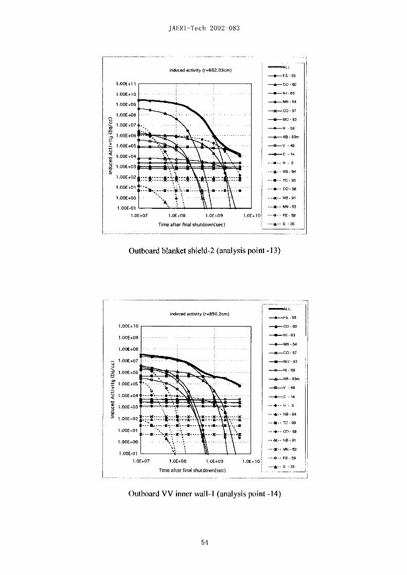
induced activity (r=882.03cm) -ALL- -55
1.OOE+1 1 -*C - 0
---MN -54
O- 57
U ~~~~~~~~~~~~~~~~~-I*-MO -93
~,1.OOE+07 NI- 14
1.00E+06 ------ - - -- NB -93
1.0OE-O1 ---- V 4N-9
1.O1.0 E+0 C.EO .E0 .E1 -- 14-5
Time after final shutdown~~~sec) --- A- N5 -54
TC- so1.01DE+01 -- ----- ~~~~-6-NI-6
1.00EA0 ~~~~~~~~~~~~~----O N-57
1.0OE-01 ~~~~~~~~~~~---- M -3
1 OOEA7 10A .0E ---0-NI -59
----------- ~ ~ ~ ~ ~ ~ ~ ~ ~ ~ --- H
-1Outoad lake hild2 anlsi pin -3
1.OOE+10OOO-6
1. E+0 NO-i0 -630 OE1
54~~~~~~~~~~0M 5

JAERI-Tech 2002-083.
induced activity (r=895.2cm) - L-- - E- 55
1 .OOE+09 --- CO -60
1.OOE+08 ---------- ~ ~ -U- NI -63
6 N- 541.OOE+07- -- - -- - - -
3 CO- 57
1.00IE+06 0 ~~~~~~~~U-MO -93
1.OOE+05 ~ ~ ~ ~ ~ ~ ~ ~~~--NI - 5 9
11.OOE-i04 - -- - ---- B 93S ~~~~~~~~~~~~~---V -49
U %_ 6 ~~~~~~~~~~-- C -14
A -t- ~:~ :\:~-4---H - 3
1.00E+01 :.a fLU. -
- ---- 1--'~~~~--~-~~--m--------X---TC -9 9
----- CO -58
--- X--- N8-91
1.00E-02 ... ...... -o --- x---MN-53
1.00IE-03 ~~~~~~~~~~~~---Q---FE -9
11O0E-i07 l.OE1+08 1.OE+09 1.OE+1O - S -35
Time after final shutdown(sec) -- 9 3
Outboard VV inner wall-2 (analysis point - 15)
-ALLinduced activity (r=959.2cm) FE -
10E+05 -- CO- 0
U-NI 631O0OE+04 - --- -i- - -- -
* . ---~~~~~~~~0MN 54
1.OOE+03; m CO--5
M -MO 931. DE+02 .....
N0---59
1.OOE+01 6N 3
S E ~~~~~~~~~~~--V -491.0OE+O :..---C 1
C~~~~~~~~~~~~~~~~~~~~~~~~~~~6C1
1.00IE-01 ----------- ... 3-U--IC-9
1.OOE-03 ....-...... 4--- CO -58
.-----MN- 53
1 .OOE-05 --- *---FE -59
1.OE-i07 1O.E+08 1.OE+09 1.OE+10
Time after final shutdown(sec) ---- R9
Outboard VV outer wall- (analysis point - 16)
- 55 -

JAERI-Tech 2002-083
induced activity (r.964.2cm) -ALL
-55
-ACO - 0
1.OOE+03 ~ ~ ~ ~ ~ ~ ~ ~~~--MN -54
1.00E+02 M CO ~~~~~~~~~~~~~~~- 57
1.OOE+01 0~~~~~~~~~~- - MO -93
~ 1.00E+00 -- NI -.
--- ----- & ~~~~~~~A- NB -93m
21 ~~~~~~~~~~~~~---V -49
--.- X....A-N --- -C14
1OOE-03 ---- *---*--h-- - -£--£--
1.00E-04 --- 1----------NB -94
1.OODE-05 -- 11--- - TC -99
1.OOE-06 ~ ~ ~ ~ ~ ~ ~~~~~-4-CO -58
--- X- NB -911 .01DE-07
--1- MN -531.OOE-08
--0-FE -591.OE-i07 LOE-i08 1.OE±09 1.OE+10
--- A--S 35Time after final shutdown(sec)
Outboard VV outer wall-2 (analysis point - 17)
-- -- LLinduced activity (r- 1 030.42cm) FE- 55
1.01DE+06 ~ ~ ~ ~ ~ ~ ~ ~ -ACO -50
1.00E+05 ~ ~ ~ ~ ~ ~ ~~~~--NI -53
MN-CO - 57
1.OOE+02 ~ ~ ~ ~ ~ ~ ~ ~~ N-MO -93
--0--N I -59
&N- 93m
-1--V -49
-O-C -14<1.OOE-02a .X
- --- - - -5 ---*-- H - 3
E-03 - :~~~ ::*::: :::~~~~ ---A-NEI-94
1.OOE-04~~~~~~~,--q-- --C -5
--40--TE-59
1.OE1+07 1 OE+08 1OE+09 1.OE+ 10 -- -S -35
lime after final shutdown(sec) -I-G ZR 93
Outboard TF coil casing-I1 (analysis point -18)
- 56 -
JAERI-Tech 2002-083
induced activity (r- 1041.8 cm) -ALL-- -55
-- CO -60
1.00IE+03, 0 ~~~~~~-4MN - 54
-N-CO -57
1.OOE+02 0 MO ~~~~~~~~~~~~~~- 93
1.0011+01 --------------- ~~~~~~~59N- 93m
1.00IE+00 10 v ~~~~~~~~~~~~~~~~~~~- 49
<u 1.OOE-01 ----- ------ C -14
w --4--~~~~~~~~~~~~~~~~~~H - 3
U 1.O0OE-02 --- r------- -- K -4-TC9
1.OOE-04 ~- ~~~~~~ * - * ~~~~~~--- X-NIB-91
1.00IE-06 G~~~~~~~~~~-4- FE -59
LOE+07 1.O1E-i08 1.O1E+09 11O0E+1 O[_1
Time after final shutdown(sec) Z-93
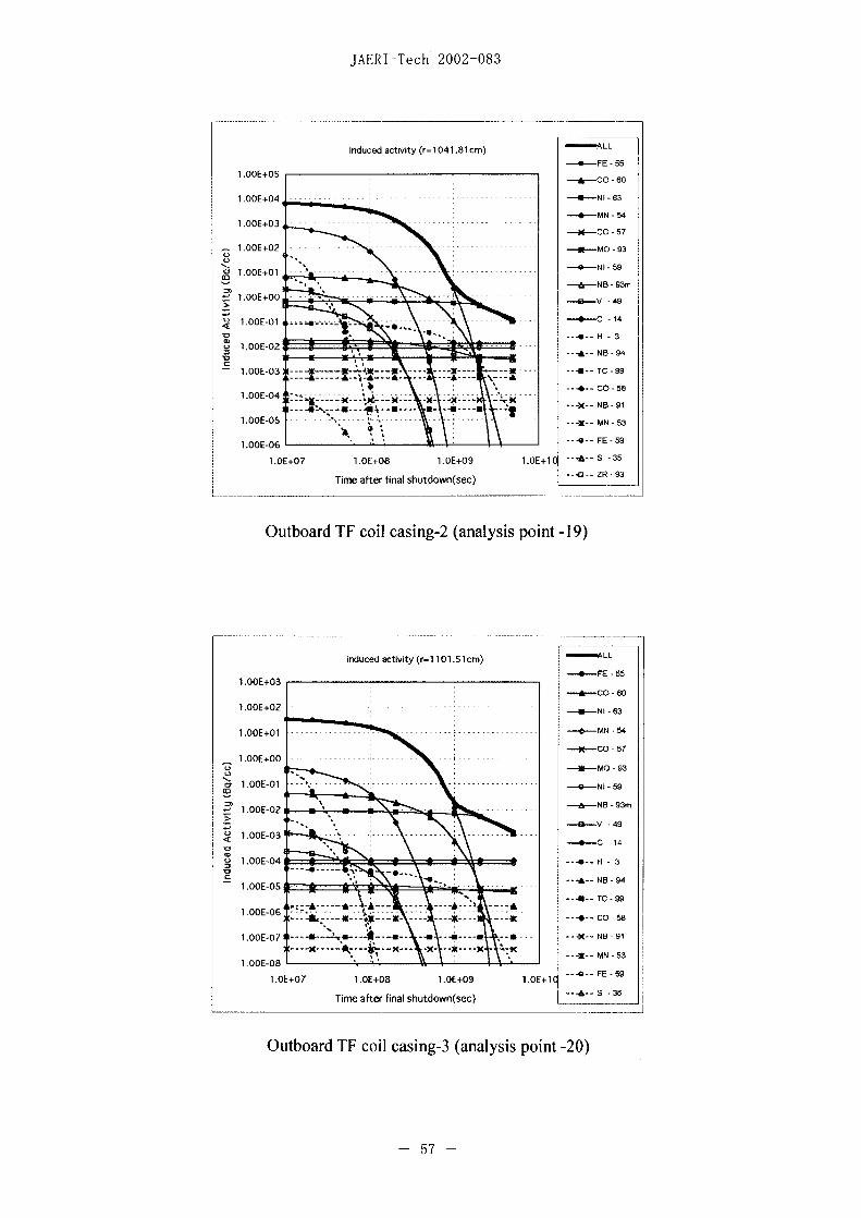
Outboard TF coil casing-2 (analysis point - 19)
induced activity (r-1 101.51cm) W L
E- 55
-- CO -60
---- NI 63
1.OOE+01 o ~~~~~~~4-MN 54
1.001E+00 ----- X ~~~~~N--CO 57
o -U---~~~~~~~~~~ MO 93
cr 1.OOE-01 -0--------- -- 4-NI -59
-6-NB -93m
--f -V 49
<1 11.0OE-03 0 ~~~~~~-4-C -14
C ---A-- ~~~~~~~~~~~~~~~~~~~~NB -94LOCIE-05 X. ~~~~~~~~~----TC -99
1. U--06 -------- ---- O S
1.OOE-07 ---.-- 4----U----u -e-- ---X-- NB -91
L.OE+07 1.O1E-i08 1.O1E-i09 1.O1E+] --- 0-- FE -59
Time after final shutdown(sec) - - S -35
Outboard TF coil casing-3 (analysis point -20)
- 57 -

JAERI-Tech 002-083
induced activity (r= 1 1 11.86cm)LL---- FE 55
-- CO - 0
1.OOE+01 ~~~~~~~~~~---NI1 63
1.OOE+00 6 ~~~~~~~~0-MN -54
1.0OE-01 % CO ~~~~~~~~~~~~~~- 57
-46-MO 93
fi --04--NI- 59
21 ~ ~ ~ ~ ~~~~~~~~~~~--NB -93m
z; 1.OOE-04 --- -- - -49
1. -E4-5C -14
C-) E*- $A-- H -3
--- A- NB -941.OOE-07 ------- X--- -5-
1.OOE-08 2* -
---X- NB -91
1O0E+07 LOE+08 LOE+09 1.OE+1O0 --- FE -59
lime after final shutdown(sec) --- -A- -3
Outboard TF coil casing-4 (analysis point -2 1)
- 58-

JAERI-Tech 2002-083
Appendix-2
Clearance indices for TF coil casing, VV and blanket
- 59 -

This is a blank page.

JAERI Tech 2002-03
Araysis pnt: Surfaceno CS ccil case
),,bold Region 1 ~~~~OtbordRegion
10 I-O~~~~~otO~----0 Nb-91
2 10~~~~~~~~~~~--t 115 90 0 ..... . .......... 1 3 - oa
-w iot.~~~~-0-Ni6
4 ' . .. . . . . . . . . . . . .. . . . . . . . . . . . . . . . .
on......w...... ...... ........... ....
W1 0- .. . . .. . ... . .. .
W 1
o< 11 0 ......
10 .. ... 20 40 60 80.................... . 100....
lim after-fina shudow -(yar
101 ~ ~ ~ ~ ~ ......... - -- -5 -- ------ ---
12
0 20 40 60 80 100
Time after final shutdown (year)
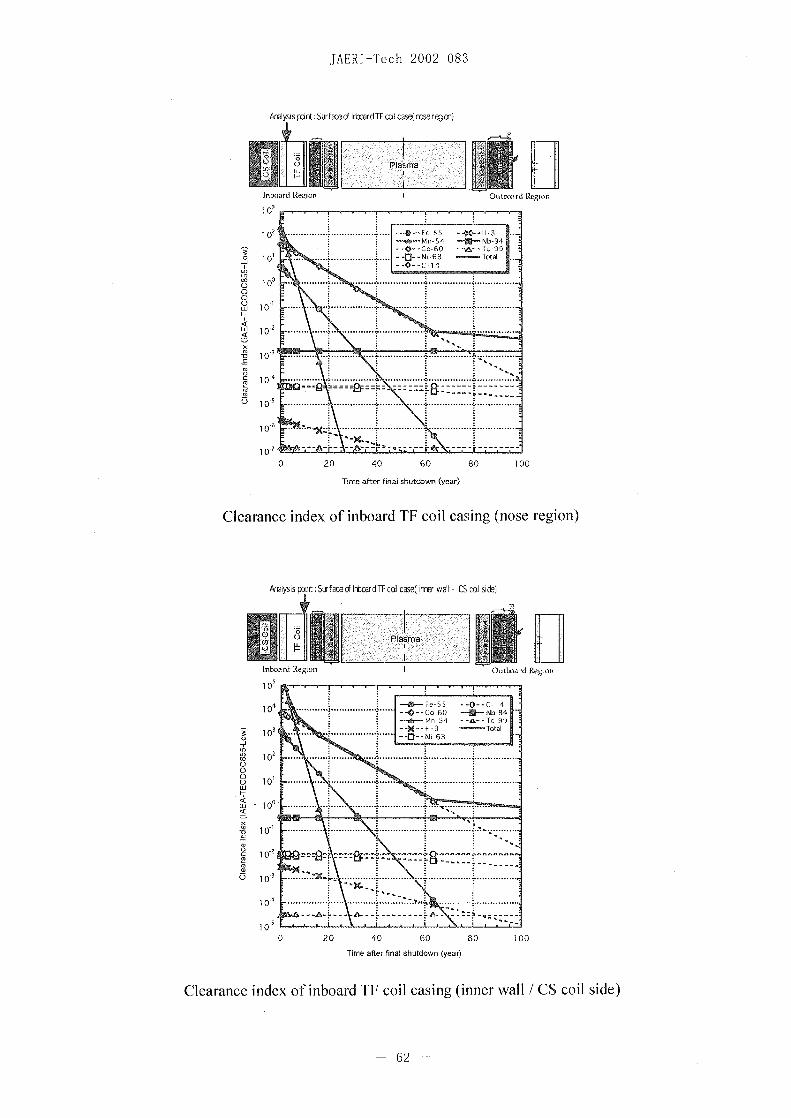
~~~~Clearance index of inordT coil casing (oergo Sci ie
Amyssdn:Sra~olrmrTcclas~nsree- ~c61ie
JAERI-Tech 2002 083
Asalysis p nt: Surfaced lxamrdTF ccii cease( repom)
Inboard IZ~~gion I OuitLx>4 > Region
10- ~ ~ ~ ~ ~ --- C1
i on .............. .......
0
to 0 - -.....10'~~~~~~~~~~~~~~~.................
0 060 8
aftr..na.sutown.. ar
ClaacX ne fibadT olcsn ns ein
Analysi ..nt:S .fac I ....d c. lcas).e. wll..CSc.
1 0 rf-----1
T 10-f4--N0 6310
I bad e.o 0.tmr eio
40 10,
CS ~~~~~~~- eS
o 10 ~~~~~~~- 3 - oaI- -~~~~~~~~~~~~~~~~~~~~~
'c
in 1
1 0-2 ------s
10O
0 0 40 60 80 tOO
Time after final shutdown (year)
Clearance index of inboard IT coil casing (inner wall /CS coil side)
- 62-

JAERI-Tech 2002 083
AMulysiu ou(: Surface of ircrTF wI case (asmna si®~
Inboard tRegion IOutkba rd Region
10,
10, ............. . .. ......... 0-- 1
1 0 ... .................... --0- -C-GO --sa- - C 9910 ~~~~-V0--NI-GO -- Totai
W3 10 ... .. ...
W 1 0 ..............
0 ......... ...
0.10...
1 LEFe 1--
1 0'70 20 40 60 80 100
Timne after f inal shutdown (year)
Clearance index of inboard TE coil casing (plasma side)
MA yiu pint: Surface d lnbxard W Outer sfd (CS cal side
Inboard R,.oon ~~~~~~~Outboard Region
00
0 20 40 ~~~~-0 -C60 110 1009
101 --Ni-663

JAERI Tech 2002 083
NAmysis prnt: Srf aceof W uier s~d (1asmasi d)
Inboat di Region Outboard Region
-Ni-63 1Total
<, 10O
70
O 1
I-I
0 20 40 60 80 100
Ttme after shutdown (year)
Clearance index of inboaid VV outer shell (plasma side)
kalysis pint:StrfaceotfWire shdl (CScil side
Inboard Region ItifadRegion
10o
101 .............. I- t 60b --E- -b941
I---MnS3 TohSE
-j I-D ~~~~~~~~~Ni-63
0
ci 10O .......<
0 20 4 60 0 0
1o~ t 2%-.64 -.

JAERI-Tech 2002 083
Amayi ian: Surfac ofW iran s~ Oras i deo)
Inboard ORgio o ubr i e
~ 1o~ '~) . flt %n~t ?0-.
0 1
0 20 40 60...... . .......... ... 00. .
1 c), ~ Tm atrfia hudw (er
Cleaanc inexo. ibor.V.inr.hel(pdsasie
-J0-
020 4 0 8 0
10,
~~~~ 10 I..~~~~~0--CO6 -5--b9
10 .......
1003 20...40 ..0...... 0
iq~~~~~~im fe ia sudw er
Claac<nexo norolaktsil2(Sci ie
W ....~~6 ........

JAERI-Tech 2002 083
AroysS p Inl Strface of Blarket Sredd( Oasma sice)
111900 rot Region ~ ~ ~ ~ Oitl~ir Roo
10..
10 -0 CobS ~~-U-c-SI--H-3 - Total
C) ) -0 - i6
Iii.. . . . ... . . . . . . . .. . . . . . . .
0 1 . . . . . . .. . .. . . . .. . . .. . . . . .. .
W0
0 20... ...0 . 608.0
........... Tim e afte ........ ...utdow n .(year)
Clerane index of inbardblnke.siel .(pasa.sde
1 20-0--60 -U--Nb-9Tim ate --na sutow (4ye-a r
MIn
1~~~~~~~~~~~~~~~~~~) ~ ~ ~ ~ ~ ~ ~
Tim ate fnasutow (year)
Cleaanc index of....... oubor. bane.sied(pasasie
1 I .... ...... ..... ......... ...6 6....

JAER1-Tcch 2002%083
Am lss pm t. So.(ace of Blar~oet Shidd] o ryost side)
Intmaud Region 1 ~~~~~Ouitboard Region
10 ~~~~~~~~~~-0. b9-0n-54 -- O-99
10? -... ...... 54 .- Tl0 N- 6
W 100'.....-.............
o I. . . .. . . ... .. . . . . ... ..
10
1 01, .
0 20 40 60 80 100
Time after final shutdown (year)
Clearance index of outboard blanket shield (ryostat side)
Aidysispdcst: Surface - Winnurscll(plasma sicvŽ)
In~~~oard Region 0.~~~~~Qtftosrd Region
1 o7
--0-- Co-6O --WN-94--l--iGO --A-f 99
-j 101
0 1O1 .... - -0 _ _ _ _ _ _ _ _ _ _ _ _ _ _ _ _ __... ... ... .. _ _.. ... ..
o o0-U - ...... . .......
i- Of
1 xx 10 ........ .. ...... ..... .. ..... .......
C)
1 0-
0 20 40 60 80 100
Timne after final shutdown (year)
Clearance index of outboard VV inner shell (plasma side)
- 67

JAERI-Tech 2002-083
Anaysts ptnt : ur face d W irmns fI( cyotatI uicL)
0
tnloa rut Region I Outboard Region
>u 10 _ _ _ _ _ _ _ _ _ _ _ _ _ _ _ _ _ _~~~~~~~~C 1 in:... ............. o 6 b 9
0 20 40 tOO 80 100~~~TC-9
0>4.. . .. ... .. .. 0.
10 -O 60 -U--Nb.....4
> 10-
0 20 40 60 80 100
Time after final hutduwn (year)
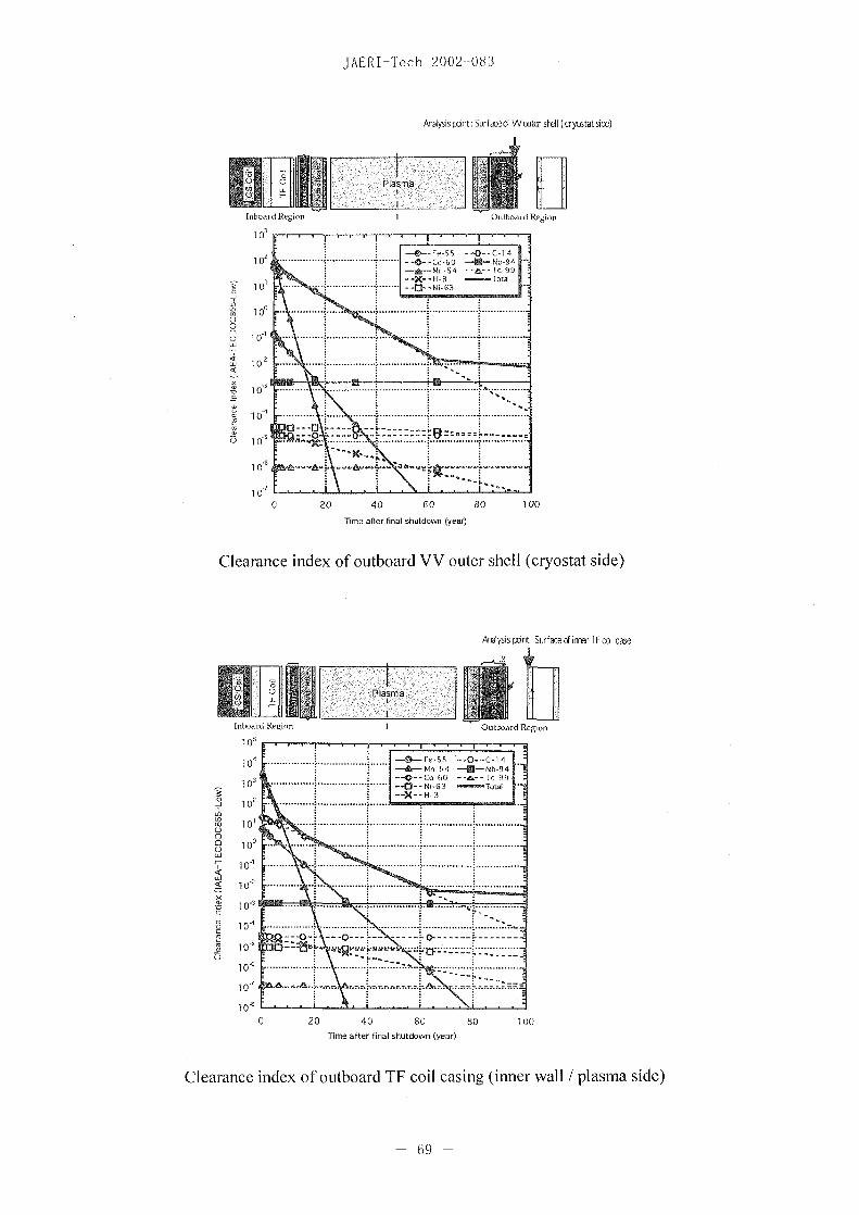
Clearance index of outboard VV outer shell (laosma side)
A68i it uraeo otrsW Osasc.
JAERI-Tech 2002 083
Anaolysis pnt: Surfaceocf Wouaer-d w (crycatat sidef)
Inboa rd Regi on IOtb oard Region
. . ---- ~~~~~~~Fe 55 --0--C1 1410 --0-......... -n60 -- NS 94
-~~~~~ 1 - X~~~~~~~~H-I- - Totali 10 .. .......... --.. -. Ni-en6
0
F-
Wj 10O .. ... ...
C o a - -
1 O'0 20 40 60 80 100
Timne alter final shutdown (year)
Clearance index of outboard VV outer shell (cryostat side)
Arnysispxint: Surface of irra TFcl case
Inboard Region IOutlrard Region
4O. ............... es --0--c 1A10 ~~~~~~~Mn-54 -- N-94
3 . -0 -~~~~~~~~~~Co-hO --a-C 9910 ~~~-f - Ni-63 -TntaI X -~~~H-3
o 2-j 10 ..............
xo c-
~~~~~~~~~~~~~~~~~. . . .. . . . .. . .- . . . . . . . .
1000 20 40 60 80 100
1Tiwo after final shutdown (year)
Clearance index of outboard TF coil casing (inner wall /plasma side)
-69 -
JAET-Tech 2002-083
Analysis pint: Siufaed iaer TF ccil case ( cryes at side)
Inboard Region IOutboard Region
102 -0--~~~~~~~~~~Co-60O N 9U-164-~A- Mo 54 -a- r99
~~ 101 X::H~~~~~~~~~~3 -Oc~~~Ttal
0
1 -i 1
0) -s~~~~~~~~~~------- ---
-D 10
0 20 4 0¾ 0
Time after final shutdown (year)
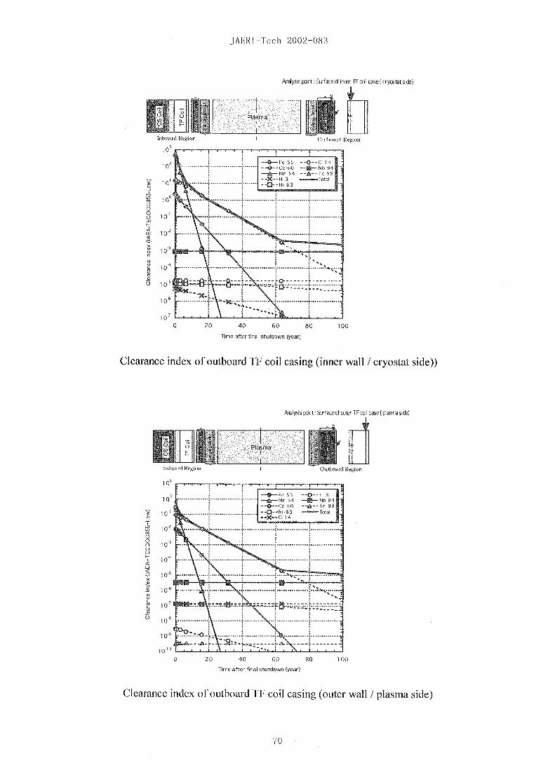
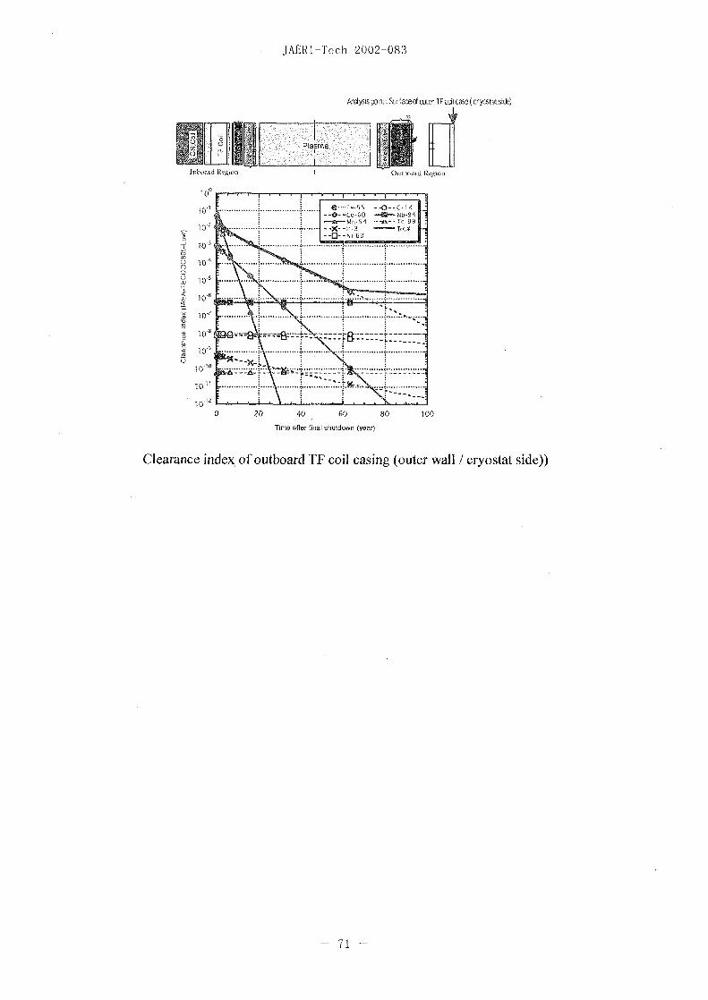
Clearance index of outboard TF coil casing (inner wall /cryostat side))
Analysis ant: Sfaceef cute TF cI casea(plasmasi®~
Inboi uboard Region 0toFtzgo
0 0,55 --0 ---- fe-H 310 .............. Mn 54 -U]--Nb-94
o . . I~~~~~~--X--C-1 41-
o 510 .... .....
F- ~~~~~-101
0 20 4 60 0 0
10 ~ ~ ~ 7
JAERI-Tech 2002 083
Argiysis prnt: Stirface of cuter iT cal case ( cryotat sid)
fnhcoard [fcRofl0,tx~tdRgo
102
C) . 20...... 40....... .08...00Tieafe fina -hut on -(year)
Clearance index of outboard TF~~-L coM cSing (oute wal/cysttsd)
10 1 ...... ......... .... H 71t1

This is a blank page.

JAERI-Tech 2002-083
Appendix-3
Classification of solid radwaste
- 73 -

This is a blank page.

JAERI-Tech 2002-083
Classification of radwaste for its safe disposal in Japan
Prepared by Takeshi Maruo (JAERI)
November 24, 2001
In japan, radioactive solid wastes are classified for regulatory purposes as follows:
* High level radwaste (HLW):
"HLW refers to the radioactive waste, which comes out from the reprocessing of
nuclear fuel. This is very rich in alpha emitters as well as beta gamma emitters.
The geological disposal (a few hundred meter deep underground) with natural and
artificial barriers is required of HLW for regulation;
* Low level radwaste (LLW):
Japanese regulation requires that LLW shall be classified into any of three classes
shown in TABLE-i and shall be disposed in accordance with the approach specified
to the class. In addition, activated waste is categorized into LLW
TABLE-i: Classification of LLW nd approaches for the final disposal in japanClass Criteria for classification Approach for the final disposal
(Bg/ton)Li waste H-3: C Ž 50P** Burial in several ten meter deep underground with
C-14: C Ž 37G* artificial barriers (concrete pit or more effectiveK-40: C Ž 170M** structure).Ca-41: C Ž 3.1G*Co-60: C Ž 11.1T* The depth shall be determined appropriately based onNi-63: C Ž~ 1.11T* evaluation as for radiation exposure resulted fromSr-90: C Ž 74G* extremely unlikely events (radiation exposure up to a
Nb-94: C 1G** few ten micro-Sv/event can be approved for anTc-99: C Ž 190M** extremely unlikely event).Cs-137: C Žt 1.l1T*Eu-152: C Ž 360M*
an alpha emitter: < 1.l11G'L2 waste H-3: 3.0G* < C < 150P** Burial in approx. 10 m deep underground with artificial
C- 14: 1 10M* • C < 37G* barriers (concrete pit and a clayey soil layer).
Ca-41: 150M* • C < 3.1 G*Co-60: 8.1G* t• C < 1.1T*Ni-63: 7.2G* < C < 1.11T*Sr-90: 4.7M'* < C < 74G*
Nb-94: 18M** < C < 1 IG**Tc-99:9.OM** < C < 190M**Cs-137: IOOM*: <C < 1.11T*
Eu-152: C < 360M*an alpha emitter: C < 1.11G*
L3 waste H-3: C < 3.OG *Burial in near surface (a few meter deep) underground_________ _______________________without artificial barriers
- 75 -

JAERI-Tech 2002-083
C-14: C < 11OM*Ca-41: C < 150M*Co-60: C < 8.1C*Ni-63: C < 7.2G*Sr-90: C < 47M*
Nb-94: C < 18M**Tc-99: C < 9.OM***Cs-137: C < 100M*Eu-152: C < 360M*
________ an alpha emitter:C_<_17M* ______________________Note "C" means concentration of radioactivity in waste.
M =le+06, G =le+09, T =le+12, P =le+15, E le+18A value with a single star-mark (*) is quoted from the Article 13-9 of the governmentcabinet No. 324 for "the law for regulation of nuclear source material, nuclear fuelmaterial and reactors".A value with a double star-mark (**) is not enacted yet, but it is used in the examinationof safety approaches for radwaste disposal that the government has held. The value issuch that can bring 10 micro-Sv/y to a member of the public after 300 years fromdisposal. All the credible pathways of internal and external exposures due to release fromnuclear regulation on radwaste are considered in the evaluation.
During regulatory control (<300 - 400 years), radiation exposures of a member of the
public shall be maintained ALARA by radiation shield; prevention of human access to
the waste; and monitoring of radiation and radioactive materials in the environment.
A target value of 100 micro-Sv/y is recognized appropriate for ALARA.
After the control duration, internal and external exposure from all the credible radiation
exposure pathways due to buried waste must be less than 10 micro-Sv/y or a few ten
micro-Sv/ event.
- 76 -
JAERI-Tech 2002-083
Appendix-4
1. L2 limit indices for major tokamak components
2. L3 limit indices for major tokamak components
- 77 -
This is a blank page.

JAERI-Tech 2002-083
1. L2 limit indices for major tokamak components
1 0-L2 wn* indx for H-3is below 1O0 at final shutdown.
U-X-Ni3
7 I Tc99I
10 I.~~----- - :--
2 10 4 I~~~~~~-- - ------ -
10~~~
0 20 40 60 80 100
Time after final shutdown (year)
L2 limit index for surface of CS coil casing
10 ,.Y-- H-
0~~~~~~~~o6
-8
12
13~~~~~~0
0 20............40...... ...... 0...... 8 0........ . 1 00........
10 -1 ............... T im e after...... final..... sh td w (year)....... ..........
L2 limi indexfor inbard TFcoil caing (nsergo/CScisd)
12 ~ ~ - 7
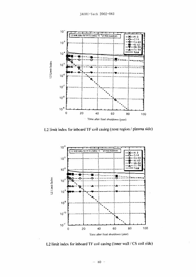
JAERI-Tech 2002-083
1 0-eL2 flin-ndexfor H-s is below 1 0 -atfna sud.X
-3 ~~~~~~~~~----c4
4 ~~~~~~~~~~~~~~Total
44 ~ ~ a--
-6 ............. .... .....
---V - Y--~~~........................ ..........
10-7
0 20 40 60 80 100
.Time after final shutdown (year)
[2 limit index for inboard TF coil casing (nose region /plasma side)
1 0-4
Ljimtidex for H-3 bsbelowl10 <at fnai ShUtdown--X--H-3
- ~~~--O)--C-141O ........................................... --0 -- Co-6O
10 -. ~~~~~~~~~~~Ni-6310~~~~6 L::1i~~~~~~N-9
10 -- --
10~ ~ ~
10
0 20 40 60 80 100
Time after final shutdown (year)
[2 limit index for inboard TF coil casing (inner wall / CS coil side)
80s -

JAERI-Tech 2002-083
1-2
U2 limit idex for H-3 is below 10 --at finaJ shutdown.
-0*--Co 60-U--" Ni63*
I-V-Nb 941
4 ~ ~ ~~~~~~~~~~-- Tot99
-J ~~~~C~
1 0
0 20 40 80 80 100
Time after final shutdown (year)
L2 limit index for inboard TF coil casing (inner wall /plasma side)
10-1Ui in* idex for H-3 is below 1 0 a k hton
-U--Ni-63
* I~~-Y--Nb-94Ia~~~~~c io~~~~~~~~~~~ - - --t 99
3 ... ... ... ... ... ..S... ... ..
CA 10 f 0 -
.6
10 8
0 20 40 60 80 100
Time after final shutdown (year)
L2 limit index for inboard VV shell (outer wall / CS coil side)
-81 -
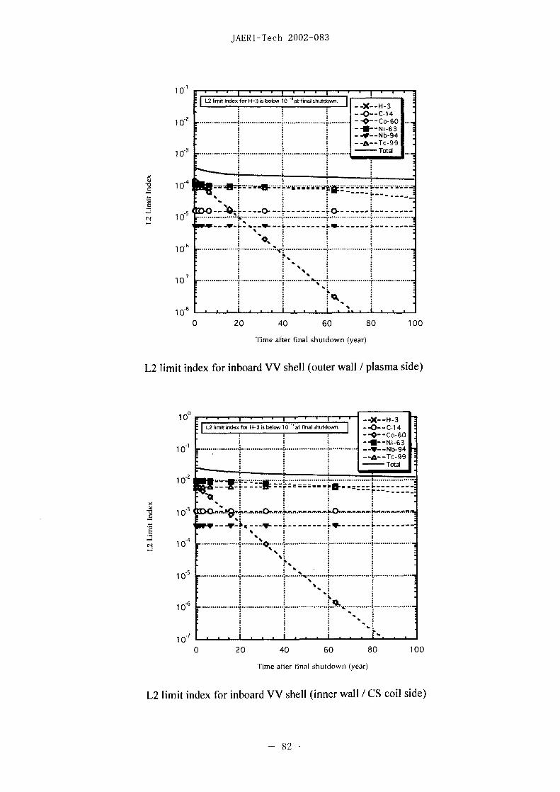
JAERI-Tech 2002-083
0-1 . . . --
[zl"--ex for H-3 is below 1 8afra shutow I'
- -- X--H-3--- C 14
-210 ........ . -Q -CO-60O .-U Ni63-W--Nb 94
10 . .......... otA
-- 4
-J --- 0 0- 0~~~~~~~~~~---- - -------
1 0
-7
0 20 40 60 80 100
Timne after final shutdown (year)
L2 limit index for inboard VV shell (outer wall / plasma side)
[2 limit kxix for W-3 is below 10' ̀at fialshtdown. -0--C-1 4- . ~~~~--0- Co-60
10 .............. .......................... --Y -- Nb-94--A&--Tc-99
-Totil
10O -
1 00
1 0,
0 20 40 60 80 100
Time after final shutdown (year)
L2 limit index for inboard VV shell (inner wall / CS coil side)
- 82 -

JAERI-Tech 2002-083
101H3sbow[2 [irtt index fo sblw1 0 at final shutdown.
-O--14-0--Co 60
-A^-- Tc99
~~~~ -t~~~~ ---
X ----------2 -- -- '- - -…-------- 1 ... ....... ......... .... ........ .. ......... ......... .
-J Z24.. 4~~~~~~~~~~~~~~- -y. O---
3~~~
1 0-6~ ~ ~ ~ ~ ~~0
0 2 0 4 0 6 0 8 0 100
Time after final shutdown (year)
[2 limit index for inboard VV shell (inner wall / plasma side)
0
-0-C-14
1 ......... E Ni-6310 ~ ~ ~ ~~ ~.............:........... ....... - Nb-94
-A,-- Tc-99
-2
---- A- ----A-~~~~~~~~ - '- ---
-40
-6
10~
0 20 40 60 80 100
Time after final shutdown (year)
[2 limit index for inboard blanket shield (rear surface)
- 83 -

JAERI-Tech 2002-083
02
0C141
10 ........ ........................... lM -N i6311-- Y-Nb 94
c-o99-Totalo
10 ..............
(4 10*
-4
100 2 0 4 0 60 8 0 100
Time after final shutdown (year)
L,2 limit index for inboard blanket shield (front surface)
1 0 -
-- X'--Nb-4-TC-4
9- N-4
10
10 ....... .
X~~~~--s ____ ______ ____ ............. __ _______-- - - - - - - - ___L ______-- - - - - ___L- - - - - - -_
1 0 ...20.40 ...... 0..... ....... 0..... 100........
2~~~~~ieatrfia hton(er
L2 limit ....index .. fo outboard... blanket.... shel. (rntsufae
3 ~ ~ ~ -8

JAERI-Tech 2002-083
100 ~~~~~1 ~ ~ ~ --X-.H-3
--O--C-60
--U-- Ni-6310' ................................. -- V -- Nb-94
-d- Tc-99-Total
10 ---- ---
107
0 20 40 60 80 100
Time after final shutdown (year)
L2 limit index for outboard blanket shield (rear surface)
101 L24- xfor H-3 is below 1 0 -'at thMa shtftdo 2J [-X 7 T ]
I.0--C-14U
10
10-- - -- -- -- --- ---
x --- & 6 6~~~~~~-- -- -. - - -
-3
C14 10 ~ ~
10
020 460 8 0
Time after final shutdown (year)
[2 limit index for outboard VV shell (inner wall / plasma side)
-85 -
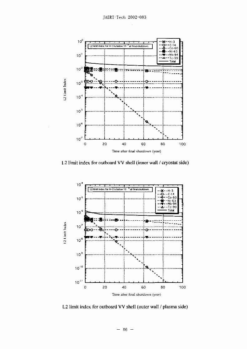
JAERI-Tech 2002-083
10 0 1 . . . 1 . r . . -X -
10 lmtidxfrH3 sblw1 a ia sudw. - -- C
-7
0 -20 ----- -40 -0 8 100
1 U4
L2tittiexforH-3isbelowlO"atfinalshtdwn.
-U- -N1 63
-s - ~~~~~~~~~~~~~~~~Total
ri 10 ......
a a I .... a~~~ ~~....... ...... .L...........
0 20 40 60 80 100
Time after final shutdown (year)
[2 limit index for outboard VV shell (outer wall / plasma side)
-86 -

J AERI-Tech 2002-083
-s _____________________________________X____H___3
108-OC1
1 ~ ~ ~ ~ ~ ~~~~~~-7-06
-9~ ~ ~ ~~~~~~~~~~b96 1 0 . . . .. .. .. . . ... . ... .. .. . . .. . .. .... .. . . . . .To a
-7
Ilk~~~~~~~~~~~~~~~~~'
12
0 20 40 60 80 100
Time after final shutdown (year)
L2 limit index for outboard VV shell (outer wall /cryostat side)
iiindex for -ismo1O 1 2--at f ii& shutdon 0 -Cj
0 o- o-G
106 -&.-~~~~~~~~~~~~~~~~~~T c -9 9
1 0r
S 0
10
1 0 ~ ~ ~ ~ ~ ~~~0
0 20 40 60 80 100
Time after final shutdown (year)
[2 limit index for outboard TF coil casing (inner wall / plasma side)
- 87 -

JAERI-Tech 2002-083
[2 ijt nx for H-3 is below 10__at fialshutdon' --O:-C- 14-.-- Co-GO
-6 -U~~~~~~~~~~~~~~~- Ni-G 310- .................. -- Nb-94
-A- - Tc-99-Totad
10 .......
82 1 0 ...... 0--......................
10
1012- ~ ............ .... J ...... .. .... ..... ................
0 20 4 0 60 80 100
Time after final shutdown (year)
L2 limit index for outboard TF coil casing (inner wall /cryostat side)
jjliitiex for H- 3 is below 1 0 - at final shutdon. - XH-3*-0-C-14
* --0-Co-GO-8 ....................................... -U -- N i-63
--- -Nb-94
-&6-Tc-99- ~~~~Total
-91 0 -...... U
--- 0 … 0----------
1 0
--- 4-…A- -- '~~~~~~---- i-- ----
-12
13
a aa......... ..... ................ . ............. iAO . .. ......
0 20 40 60 80 100
Time after final shutdown (year)
[2 limit index for outboard F coil casing (outer wall/ plasma side)
- 88-
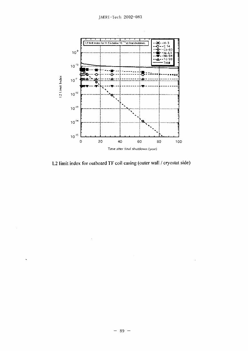
JAERI-Tech 2002-083
L2Iimitiindex for H3 irsbelow 10alo shtor --X .H 3-0- C 14
10 .. ............................ ...... -- Ni631
--- Tc-99
Total
1 0 --........y-h---- Y----------…-
-~~~~~~~ -12 ~ ~ ~ ~ ~ - --- - -
10 C
1 3
10 1 ± L 1 1 I LL...............L...............
89 -

JAERI-Tech 2002-083
2. L3 limit indices for major tokamak components
-3
--X- -H-3-- 0- -C-14
4 ~ ~ ~ ~ -- Co-6O-4M- -Na-63..
--- Nb-94-A-- Te-99
- - ~~Total
10 .. .......
6 -- - - - - - - --~~~M 1 .. ...... ... .. ... .. ... ... ... . .... ... .. ...... . .... ... ... .. ... .. ... ... ... ....
7~~~~~~~~~~~~~~~~~~~~~C'
1 0 ........... ............... ............... .. ................. ...............
020 460 810
9 ......... Time..after fina]...shutdown.... (year) .......
[3 limit indexTfor sufae f soil cyasin
--X- -H-3-- 0- -C-1 4
4 -4 Co-Go10 - ~~~~~~~~~~~~~~~~~~~~~~~~--U- -Ni-63..
--- Nb-94-- a- -Tc-99
-TotNl
10 *bf e
i~~~e C.
10
t~) 10
~- 906

JAERI-Tech 2002-083
1 0-2~~ ~X~N3
--0- -C-14
-3 -- Y- -Nb-94-- ah- -Tc-99
-Total
-410 I..t......... ... - - . ....
"fl~~~~~~~~~~~~~~~l
-6
10 - .. I 6
10 L.LJ.1..~~~~...L................................0 20 40 60 80~~~~~-6 100-6
10 ~~~~r~~r -i~~~*w- T .c-9
100
-3~~~~~~~~~~~4
10 -
x . ~ ~ ~ ~ 9-1*

JAERI-Tech 2002-083
10 -- 1 -r rr
I- -O--14
-4 -Ni-63
H-W- -Nb 94
10
cn 10 ......
10-
0 20 40 60 80 100
Time after final shutdown (year)
L3 limit index for inboard IF coil casing (inner wall /plasma side)
10
10 ............. Co 60U -- N;-63
- -- Nb 94--&--Tc 99
10 -Total.........
x 0 - 1z ......
X..
-0-
10 20 4 6. 0
Tim aferfinl hutow (yar
L3 imt nde fr nbordVVshel ouer al /CS oi sde
-s ~ ~ -9

JAERI-Tech 2002-083
10 Tt
--- 0~~~~ ~O- 0--1
0~~~~~~~~0
b-s~~~~~~~~~ -- b9
T~~~~~oa10 ................ ....................... H 3.
X ~ ~ ~ ~ ~ ~ ~ ~ ~~~I--C1
L--------4 --Ni -63 --
4~~~~~~~~~~~~~b9
1061 Tt
--- 0 3
02h
0~~~~~~~~~0
10 20.40.60.8 100........
1 .... . ..... Time. after final...... shutown.year
L3lii ide oribordV sel ine wlliCScolsie
2~~~-9

JAERI-Tech 2002-083
1 0 3~~~~~~~~~~K--
- -X-H-3 2 1~~~~~~~-O-C1l
10 ......... 1 -U - N 630
a A-Tc-99
101 ~~~~~~~~~~~~~~~~~Total
oJ010 .nr - ~ - a
~~--yb hey.. ~---------
-2-
10O
0 20 40 60 80 100
Time after final shutdown (year)
[3 limit index for inboard VV shell (inner wall /plasma side)
3 ~ ~ ~ ~ ~ ~ ~ ~ - - -
-o 1 *1'~~~~~~~- -C1
0 20.40..0..0.10
K ~ ~ ~ ~ ~~~Tm atrfia hudw (year)i----
L3 limt.ndx.orinoad.banetshel.(ea surface)...
.. ... . ... .. . 4.. . .. . .. . .

JAERI-Tech 2002-083
10 ..... .... ........... ......... ........ ho 6
-- --Ni6
1 0~~~~~~~~0
101
S~~~~~~~~~~~~
10
en 1~~~0 2 06 0
1o05
-1.
- 95 - ~ ~ - W--Nb9

JAERI-Tech 2002-083
03
--X--H-3-O--C-14
2 -0*--C-GO10 ........... .............. G.....
-V Nb-94- - ~~~~~~~-- -Tc-99
1 - ~~~~~~~~~~~~~~~~~Total
10
0-3~ ~ ~ K
en 10
020 460 8 0
Time after final shutdown (year)
[3 limit index for outboard blanket shield (rear surface)
10~ 3
-0 -C 4-0- -Co-GO
--A- -Tc-9 9-Total
10 -- ..-... .. ..........
--
10~~x 0 4 0 8 0
100 . 9 ~~~~im af ina hud- (er
L liit inex-fo oubor VVsel(nnrwl- pam ie
---a - 96

JAERIPTech 2002-083
2 .. ........ 2....................... .... l--O -C14 I ..10 I~~~~~~~--0-Co6O
- -3--Ni-63
101 -- Total
1 0
10 ............ ... .... ........... ....
4~ ~~~~~
1 0
0 20 40 60 80 100
Time after f inal shutdown (year)
L3 limit index for outboard VV shell (inner wall / cryostat side)
10 rI- r
10 Jj1..........-O--C14 ...
1O Co 60*-E-Ni-63
10 ~~~~~~~~~~~~~~~~~~Total
4.0) -
- ---U% -- ~~~~~~~~O~--…-
1 U6 '413w~~~~~r-- - -- ~6-- --- r-- - -
1 0 0. '
0 20 40 60 80 100
Time after final shutdown (year)
L3 limit index for outboard VV shell (outer wall / plasma side)
- 97 -
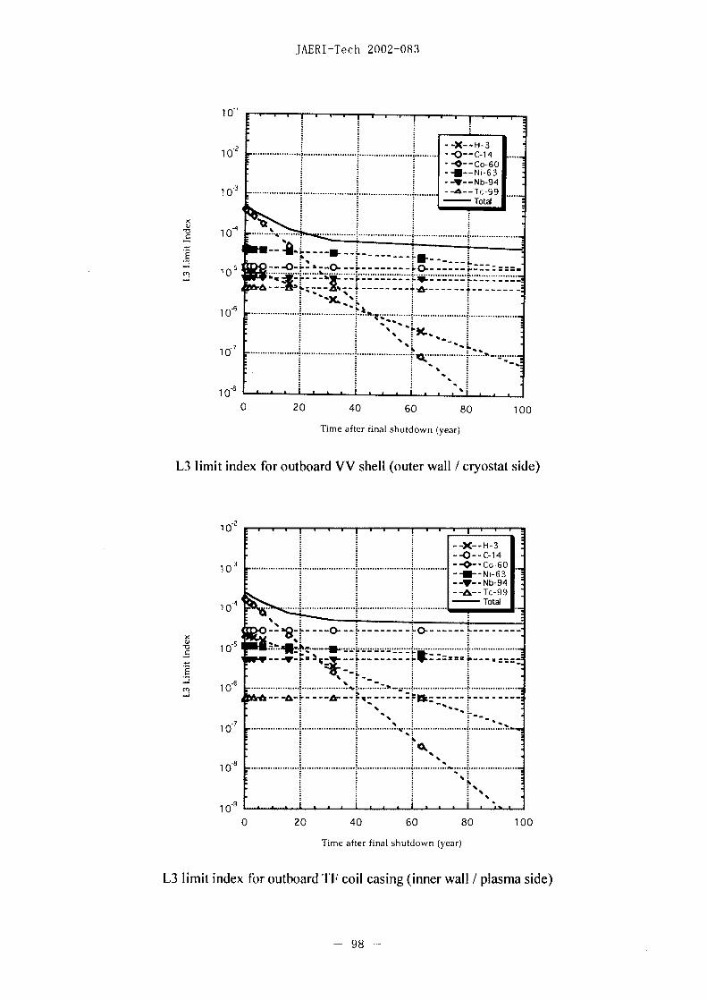
JAER1-Tech 2002-083
1 0-
-3 ~ ~ ~ ~ ~ ~ ~ ~ - - -10 ......... ................... .... O C 1
-40 0 ... 40.. ...... 0..... ...... 0..... 100.........
Tie ferfia suton yer
10 L-L --- L-2--U-- i630 20 40 60 80~~~~~~N 94 0
Tim ate fna 1 2htdwn(yar
L3 imi idexforouboad Wshll outr a-lcosta ie
en 10 ..2,
10~~~~~~~~~~~~~~C1
4 TotaTieafe fnl htdw (er
-7~ ~~-9
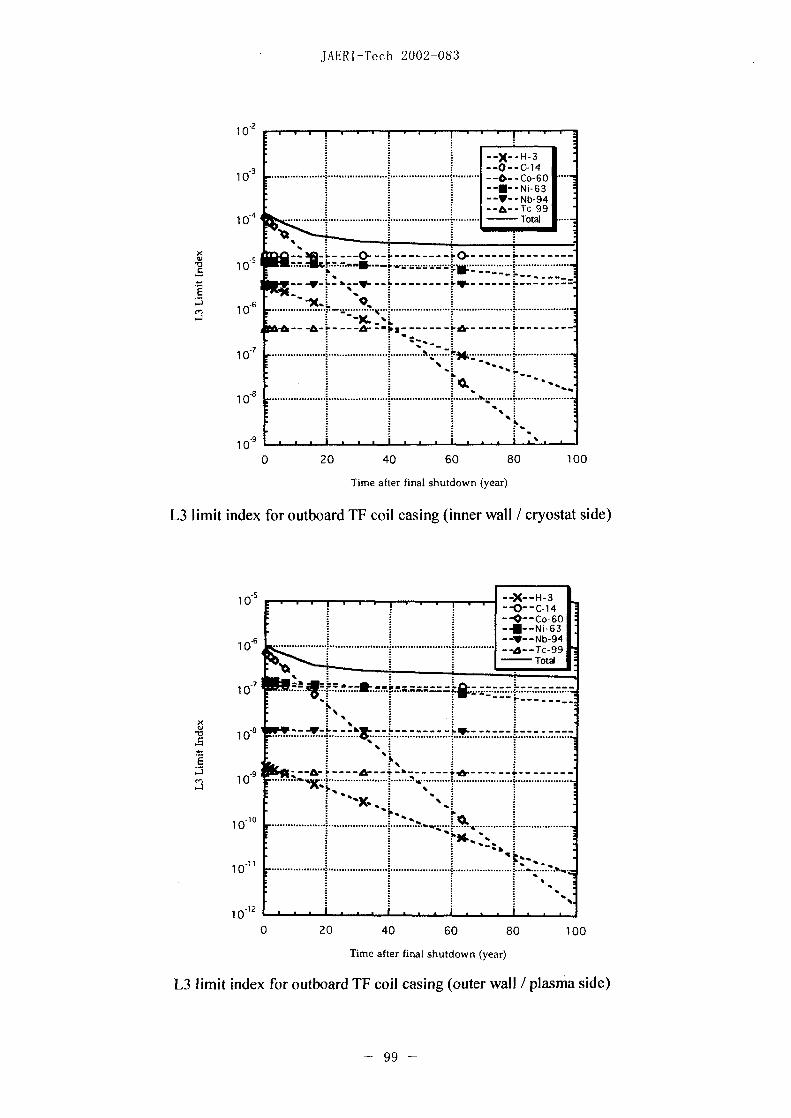
JAERI-Tech 2002-083
-2 _______________
VY--Nb 943---- Tc 99
-4~~b-
0.
0 20.0...80 10
Time after final shutdown (year)
L3 limit index for outboard IF coil casing (inner wall / cryostat side)
10 -5T I u-r-X-H-3
0 *-Co-6O
-6 ~~~~~~~- -Nb-94-h -Tc-99
Total
-710 .... - - - -
-8 -~~~~~~~~~~~~~~~~ I.- - ...........
10 ...... i............ ..........
10 ~ '~
101 .............
0 20 40 60 80 100
Time after final shutdown (year)
L3 limit index for outboard TF coil casing (outer wall /plasma side)
99

JAERI-Tech 200241083
10 J r I-- 1-- -X- -H- 3--O-C-14--0- -Co-6O
'a - ~~~~~~~~~~~~~~~Total
--- ---w-- -------
10 X
-x~~~~~~~~Z
1013
0 20 40 60 80 100
Time after final shutdown (year)
L3 limit index for outboard TF coil casing (outer wall / cryostat side)
- 100-

R#Otl (S1) (~fi
mi a2 sIJ2 tt soA a
Lit S A - I- A~L' m 5 E.R!, HEl m, h. d 10"8 x 97 -I EA 3 'F ikg fi ¼ ¼ ¾ " 0 p~ 9
as as U -~~~~ I' A SI. L 1012 'F T
t AL' V 7 K eV~ X 10' A t' m
Vt ~~~~ 3 A' ~~~ mel 10, 4 k
520 l~~~ ii7#S ~~ ed ¶0' ~7h h
W Vt 5 2 7 7~~ rad e - .602 18 x10-"J10 T t d
•0 44 Ph 2t5777 ~s r u =.66054 xWo27
kg 1W> 5' d
10'2 c)
~~3 ~fir7)t~~jbS1*flft${Ž 0 1Mifl '- n'9
l~~~~~~~I ~~~~~Hz a"- 10<'1 JX
I] ~~~~n F 7 N n~~~~~~~~g/s2 *~~~79 ' 7,hn]- A 0'
itt C '4 t & Pa N/r 2' - v b
t fL4,{*, M1 2 a A'J Nm A - AL bar
I . ¼4W 9k F W S HA' Gal V -5( DM V- W,[1M
1 5 9s - l C As 4 U - Ci Vt4 19854tPlflc1,tt5lVL{PWI . ~5t, hFAL V W/A p R'7 kJC 1 u DIAUCODATA 1986Fg3~
M 7~ 3 SV F C/V Sv rad LlcX :
ad ~ t - n( V/A Pt re rn 2. 4I1±VAt / hF 7-A 7 '9:1 9997 2- 2 S A/V
id 5S ' Wb Vs 1 A0. 1 nm"10<'m -a- 'tl-h t 7w7H5F -;$VttS )-CC
fa t 41 f t' Z T Wb/m2 ~of,1-M U CCI±4BLF:.
4 9' X '7U- H Wb/A 1 bar=0.1 MPa-1O'Pa 3. bar 4 1d, ~ l~tebktL, 7 1M a tA'9Z 'c
it ~ AL' - ./ 7 Im cd sr 1-alc-sS0m/' ~ 1IUl ~t~)-(T~tt) L, 97 A Ix Im/m
2I Ci= 3.7x 10"`Bq $
4. Ef $•8Z±ba.barn~i±~~4 ~~4 ~ N 9 L )L Bq s<1R=2.58x10-C/kg Ftio smm gt t•'
q& Ly *~~~~~ 3 9'P Gy S/kg I rad - cGy =10`Gy -1C Ahz t ' .
U - )L' Sv S/k~g l rem=l1cSv- lO2
Sv
itN(10'dyn) kgf fIbf it MPa(lO0bar) kgf/cm2
atm mmHg(Torr) bf/in2(psi)
0.101972 0.224809 1 10.1972 9.86923 7.50062 10' 145.038
9.80665 I 2.20462 ht 0.0980665 1 0.967841 735.559 14.2233
4.44822 0.453592 1 0.101325 1.03323 1 760 14.6959
Mt )l I Pa.s(N.s/m)=IPft7 X) (g/(cm.s)) 1.33322 xlO 1--1.35951 xIO<- 1.31579 x<10< 1 1.93368 x 10--
0M1tl I M2/s= I0'st( 27 F - 9Z)(CM,/S) 6.89476 x 10-- 7.03070 x 10`2 6.80460 x 10⁻² 51.7149 1
J(5= 10' erg) kgf m kW. h cal(tE ) Btu ft I bf eV I cal = 4.18605(434MV)
1 0.101972 2.77778 x 10-- 0.238889 9.47813 a 10-- 0.737562 6.24150 a 10" = 4.1845 (J4L
I 9.80665 1 2.72407 a 10-- 2.34270 9.29487 a 10` 7.23301 6.12 082 a 10" = 4.1855 J (1 5 'C)
4± 3.6 x 10' 3.67098 a 10' 1 8.59999 a 10' 3412.13 2.65522 a 106 2.246 94 a 1 02 = 4.18685 (J 2~
4.18605 0.426858 1. 16279 a 1 0< .65a0 3.08747 2.61272 x 10" {-4 r'S (At)
id 1055.06 107.586 2.93072 a 10-- 252.042 1 778.172 6.585 15 10` 75 kgfm/s
1.35582 0.1 38255 3.76616 a 10-' 0.323890 1.28506 10-- 1 8.46233 a 10'' 735.499 W
1.602 18 a IC"- 1.63377 a 10-<' 4.45050 a 10--- 3.82743 a 10`2 1.518 57 a 1 02` 1. 18171 a 0- 1
rA Bq ci u%4 G y rad 90 C/kg R 4Y Sv rem
1 2.70270ax10-'-- 1 100 1 3876 it 1100
3.7 a l0`' I 0.01 1 2.58 a 10', I 0.01
(86 I 12fM 26 H JA t)

a,
-C'1a
0
EO
0a-0
0a,0
a0C,,00
m
0
a
a
0
0
0�
�