john t. costello
DESCRIPTION
Laser Generated Plasmas - ( Stars with a Bright Future ). John T. Costello National Centre for Plasma Science & Technology (NCPST) and School of Physical Sciences, Dublin City University www.physics.dcu.ie/~jtc & [email protected]. Astronomy/Phys Society, NUI-Maynooth, Feb 17th, 2004. - PowerPoint PPT PresentationTRANSCRIPT

John T. CostelloNational Centre for Plasma Science & Technology (NCPST) and School of Physical Sciences, Dublin City University
www.physics.dcu.ie/~jtc & [email protected]
Laser Generated Plasmas - (Stars with a Bright Future)
Astronomy/Phys Society, NUI-Maynooth, Feb 17th, 2004
Outline of Talk
Part I - Laser Plasma Fundamentals Laser Plasmas: Generation, Properties & Scales
Part II - Laser Plasma UV - X-ray Light Sources
Part III - Absorption Imaging of Laser Plasmas
Part IV - Into the future Laser Plasmas & Extreme PhysicsUltraintense (Petawatt) Laser Generated Plasmas - RAL
A New Laser, 'VUV/X-Ray Free Electron Laser' - DESY-FEL
Collaborators & Contributors to the TalkLaser Plasma SourcesRAL - Edmund Turcu & Waseem ShaikhQUB - Ciaran Lewis and A MacPheeDCU - Oonagh Meighan & Adrian Murphy
Absorption ImagingPadua - Piergiorgio Nicolosi and Luca Poletto DCU - John Hirsch, Kevin Kavanagh & Eugene Kennedy
DESY Extreme-UV & X-ray Free Electron Laser Hasylab-Josef Feldhaus, Elke Ploenjes, Kai Tiedke et al.Orsay- Michael Meyer & Patrick O'Keefe, Lund- Jorgen Larsson et al.MBI- Ingo Will et al.DCU- Eugene Kennedy & John HirschPadua- Piergiorgio Nicolosi
Petawatt VULCAN Laser VUV/EUV Science & TechnologyRAL - Colin Danson U. Berkeley - David Attwood
Staff: John T. Costello, Eugene T. Kennedy, Jean-Paul Mosnier andPaul van Kampen
Post Doctoral Fellows: John Hirsch (ETK/JC) Deirdre Kilbane (PVK/JC) -2004Jean-Rene Duclere (JPM) - 2004Incoming - Hugo de Luna (JC) - Easter 2004Vacancy (ETK)
PGs: Kevin Kavanangh, Adrian Murphy (JC) Jonathan Mullen (PVK) + Vacancy (PVK/JC) Alan McKiernan, Mark Stapleton, Rick O'Hare (JPM), Eoin O’Leary & Pat Yeates (ETK)
MCFs:Jaoine Burghexta (Navarra) and Nely Paravanova (Sofia)Michael Novotny (CZ - incoming)
The CLPR node comprises 6 laboratories focussed on PLD (2) & photoabsorption spectroscopy/ imaging (4)
NCPST - CLPR
NCPST/ CLPR - What do we do ?DCUPico/Nanosecond Laser Plasma Light SourcesVUV, XUV & X-ray Photoabsorption SpectroscopyVUV Photoabsorpion ImagingVUV LIPS for Analytical PurposesICCD Imaging and Spectroscopy of PLD Plumes
Orsay/Berkeley SynchrotronsPhotoion and Photoelectron Spectroscopy
Hamburg - FELFemtosecond IR+XUV Facility Development
Part I - Table Top Laser-Plasmas
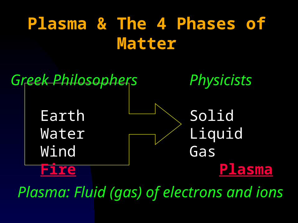
Plasma & The 4 Phases of Matter
Greek Philosophers Physicists
Earth SolidWater LiquidWind Gas Fire Plasma
Plasma: Fluid (gas) of electrons and ions
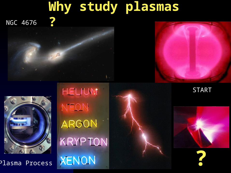
Why study plasmas ?NGC 4676
Plasma Process ?
START
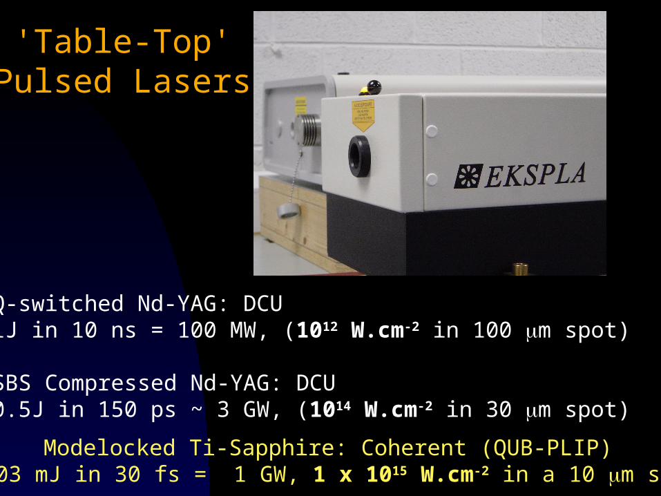
'Table-Top' Pulsed Lasers
Q-switched Nd-YAG: DCU1J in 10 ns = 100 MW, (1012 W.cm-2 in 100 m spot)
SBS Compressed Nd-YAG: DCU0.5J in 150 ps ~ 3 GW, (1014 W.cm-2 in 30 m spot)
Modelocked Ti-Sapphire: Coherent (QUB-PLIP) 0.03 mJ in 30 fs = 1 GW, 1 x 10¹⁵ W.cm-2 in a 10 m spot
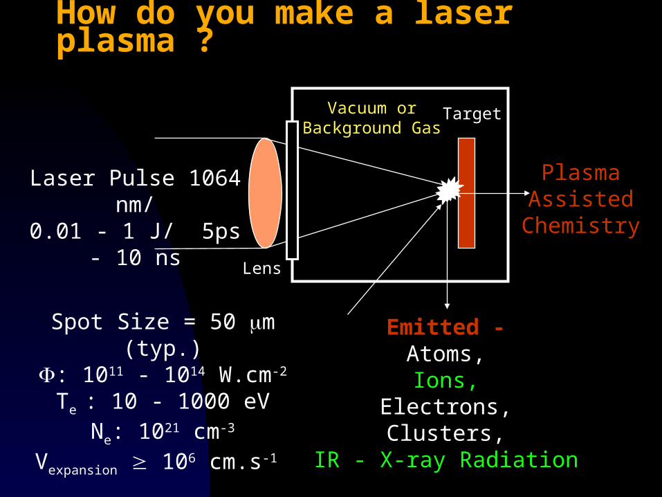
How do you make a laser plasma ?
Target
Lens
Emitted -Atoms,Ions,
Electrons,Clusters,
IR - X-ray Radiation
PlasmaAssisted
Chemistry
Vacuum orBackground Gas
Laser Pulse 1064 nm/0.01 - 1 J/ 5ps - 10 ns
Spot Size = 50 m (typ.): 1011 - 1014 W.cm-2
Te : 10 - 1000 eVNe: 1021 cm-3
Vexpansion 106 cm.s-1
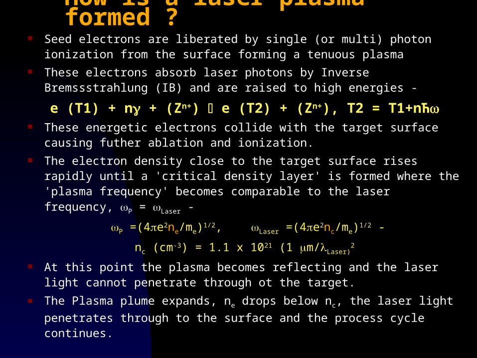
How is a laser plasma formed ? Seed electrons are liberated by single (or multi) photon ionization from
the surface forming a tenuous plasma These electrons absorb laser photons by Inverse Bremssstrahlung
(IB) and are raised to high energies -
e (T1) + n + (Zn+) e (T2) + (Zn+), T2 = T1+nЋ These energetic electrons collide with the target surface causing
futher ablation and ionization. The electron density close to the target surface rises rapidly until a
'critical density layer' is formed where the 'plasma frequency' becomes comparable to the laser frequency, P = Laser -
P =(4e2ne/me)1/2, Laser =(4e2nc/me)1/2 -
nc (cm-3) = 1.1 x 10²¹ (1 m/Laser)2
At this point the plasma becomes reflecting and the laser light cannot penetrate through ot the target.
The Plasma plume expands, ne drops below nc, the laser light
penetrates through to the surface and the process cycle continues.
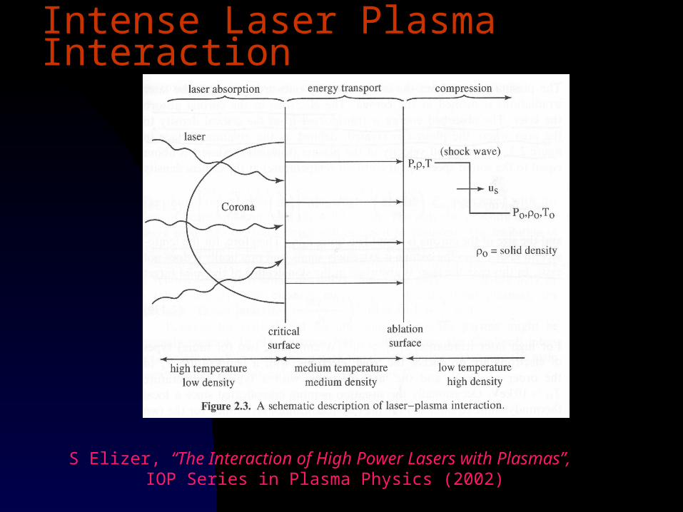
Intense Laser Plasma Interaction
S Elizer, “The Interaction of High Power Lasers with Plasmas”, IOP Series in Plasma Physics (2002)
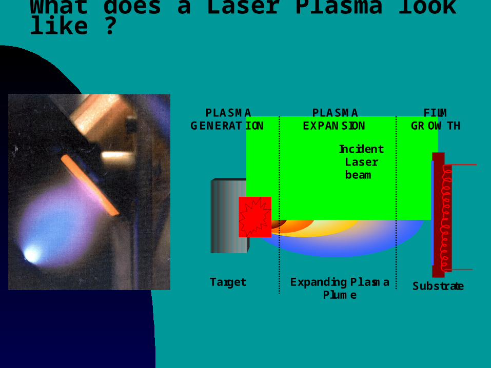
What does a Laser Plasma look like ?
PLASMAGENERATION
PLASMAEXPANSION
FILMGROWTH
Target
IncidentLaserbeam
Expanding PlasmaPlume
Substrate
Video - Air Breakdown with 150 picosecond laser pulses
QuickTime™ and aYUV420 codec decompressor
are needed to see this picture.
Video - Air Breakdown with 150 picosecond laser pulses - EKSPLA 312P
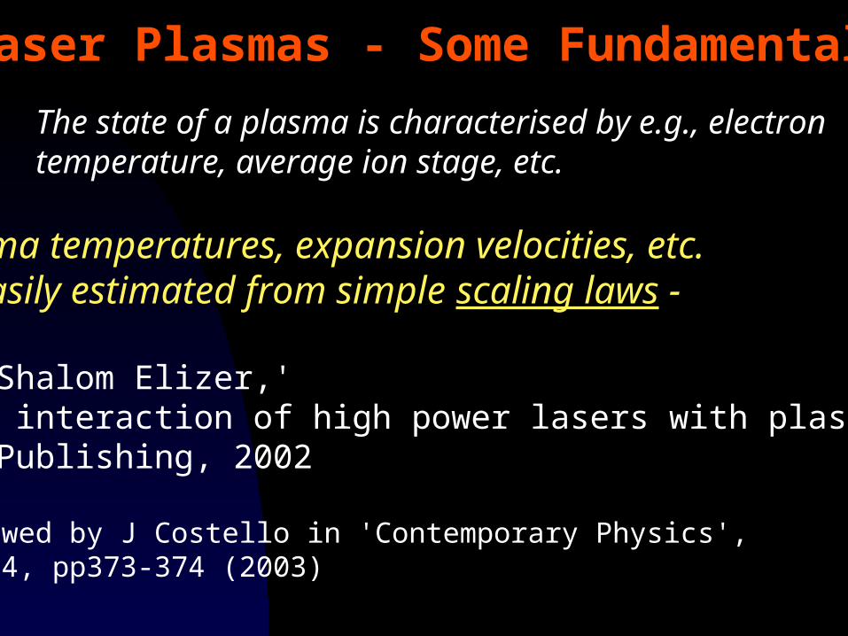
Plasma temperatures, expansion velocities, etc.all easily estimated from simple scaling laws -
See Shalom Elizer,''The interaction of high power lasers with plasmas'IOP Publishing, 2002
Reviewed by J Costello in 'Contemporary Physics', Vol 44, pp373-374 (2003)
Laser Plasmas - Some Fundamentals
The state of a plasma is characterised by e.g., electrontemperature, average ion stage, etc.
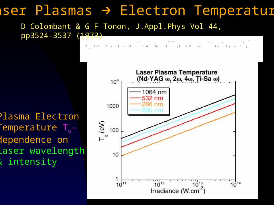
Laser Plasmas Electron Temperatures
€
TE
( eV ) ≈ 5 × 10
− 6
At . No .( )
1 / 5
IL
( W . cm
− 2
) λL
2
( μ m )
2
( )
3 / 5
Plasma ElectronTemperature Te-dependence onlaser wavelength& intensity
D Colombant & G F Tonon, J.Appl.Phys Vol 44, pp3524-3537 (1973)
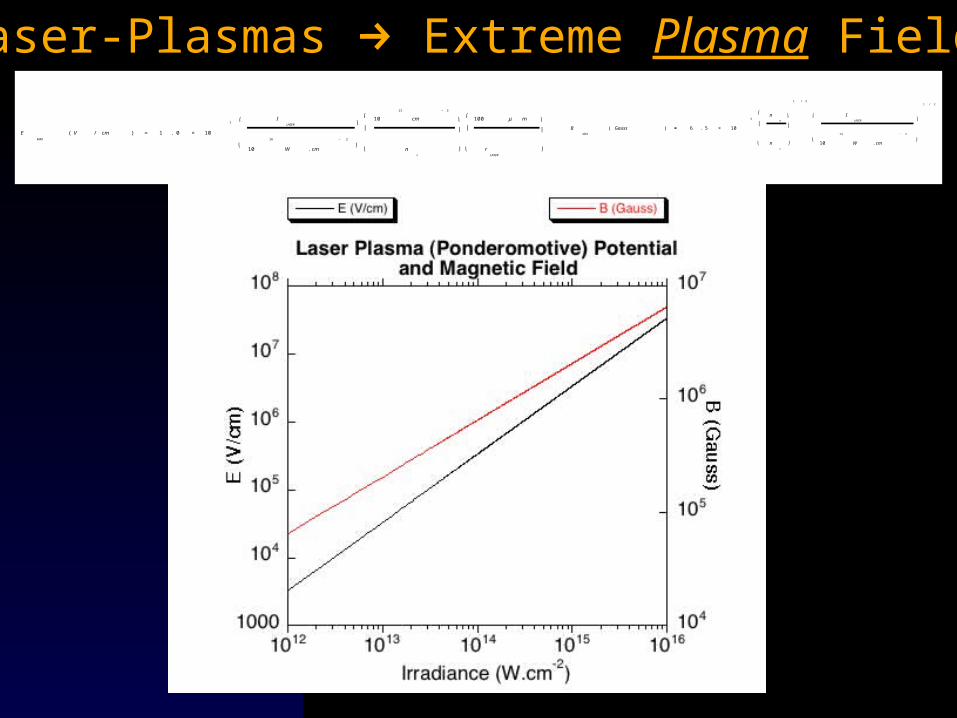
Laser-Plasmas Extreme Plasma Fields
€
EMAX
( V / cm ) ≈ 1 . 0 × 10
7I
LASER
10
16
W . cm
− 2
⎛
⎝
⎞
⎠
10
21
cm
− 3
nc
⎛
⎝
⎜
⎞
⎠
⎟
100 μ m
rLASER
⎛
⎝
⎜
⎞
⎠
⎟
€
BMAX
( Gauss ) ≅ 6 . 5 × 10
5n
e
nc
⎛
⎝
⎜
⎞
⎠
⎟
1 / 2
ILASER
10
14
W . cm
− 2
⎛
⎝
⎞
⎠
1 / 2
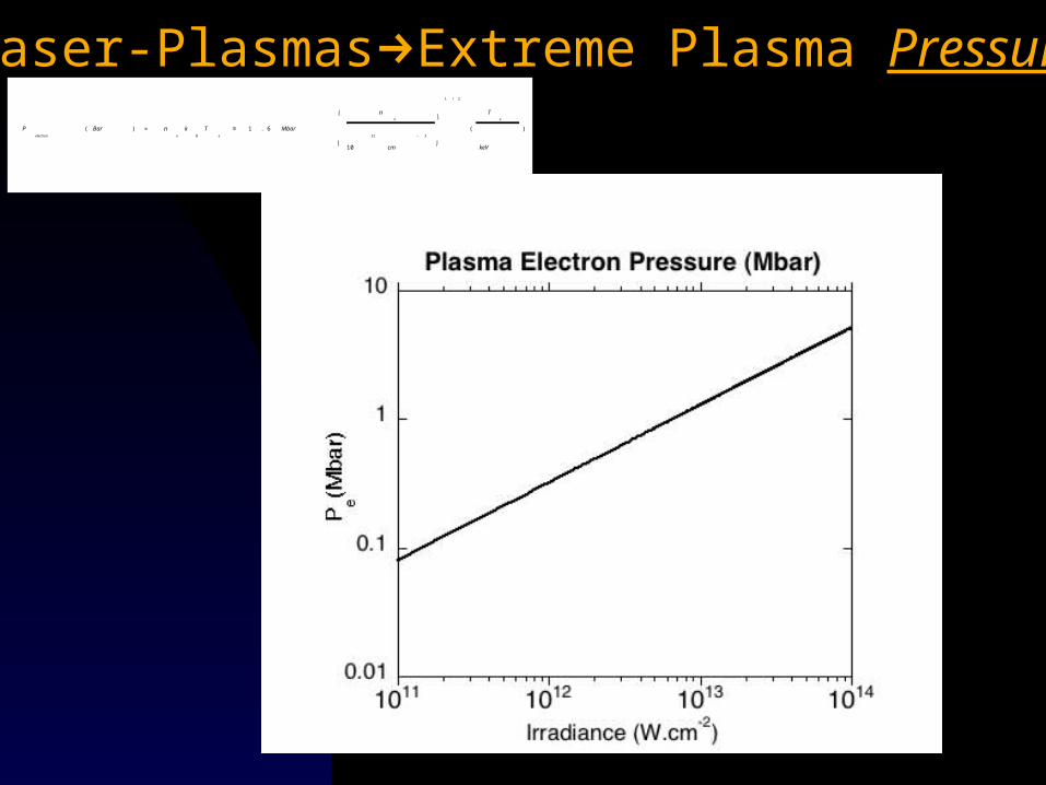
Laser-PlasmasExtreme Plasma Pressure
€
Pelectron
( Bar ) = ne
kB
Te
≅ 1 . 6 Mbar
ne
10
21
cm
− 3
⎛
⎝
⎞
⎠
1 / 2
(
Te
keV
)
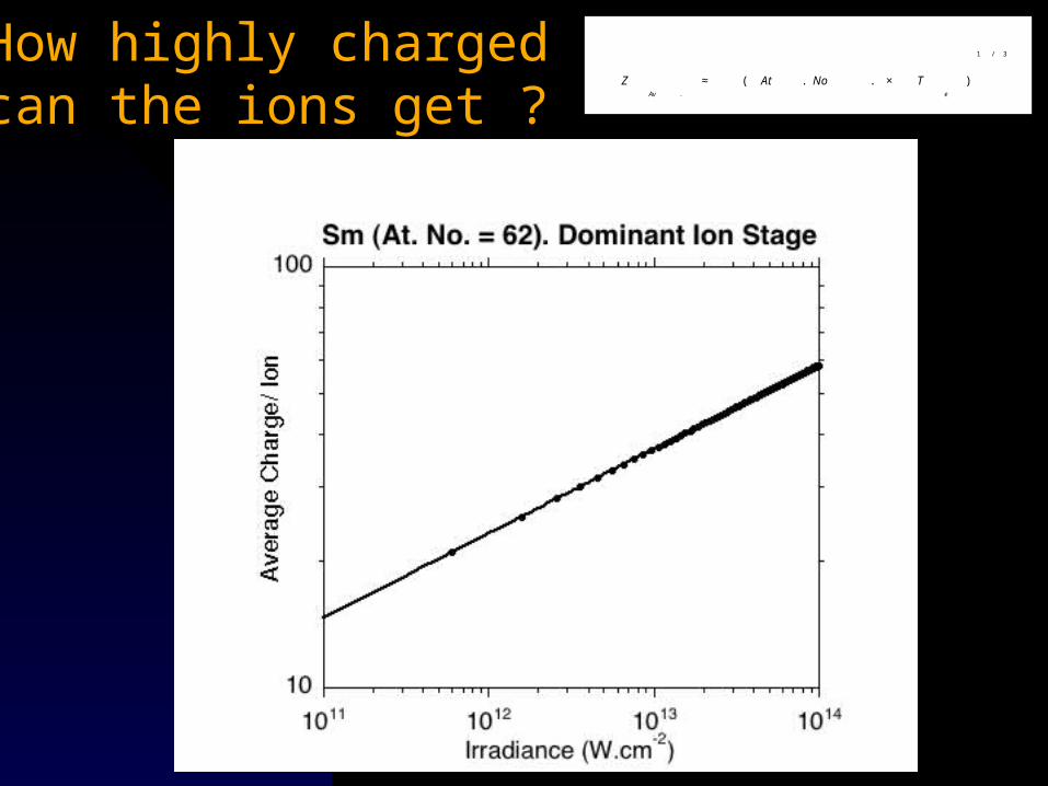
How highly chargedcan the ions get ?
€
ZAv .
≈ At . No . × Te
( )
1 / 3
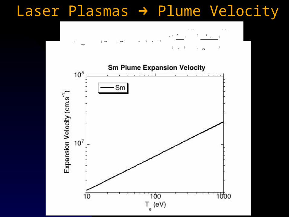
Laser Plasmas Plume Velocity
€
UBlowoff
( cm / sec) ≅ 3 × 10
7Z
A
⎛
⎝
⎞
⎠
1 / 2
Te
keV
⎛
⎝
⎞
⎠
1 / 2
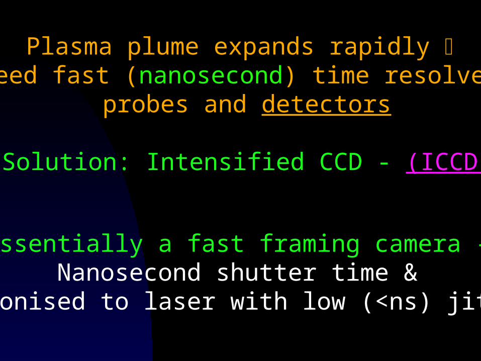
Essentially a fast framing camera - Nanosecond shutter time &
synchonised to laser with low (<ns) jitter !
Plasma plume expands rapidly need fast (nanosecond) time resolved
probes and detectors
Solution: Intensified CCD - (ICCD)
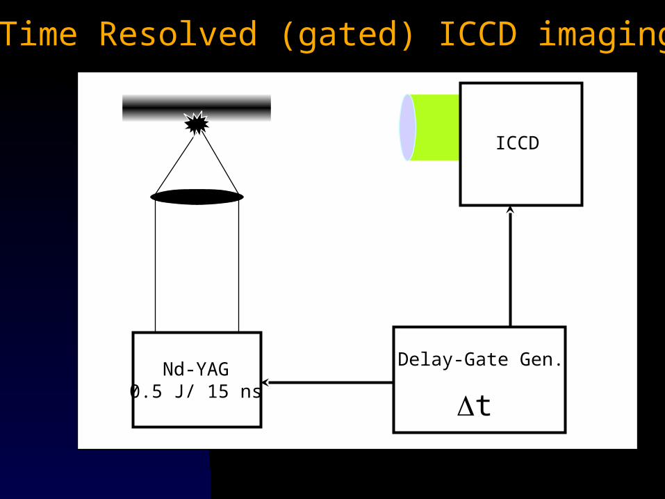
Time Resolved (gated) ICCD imaging
I
ICCD
t
Delay-Gate Gen.Nd-YAG0.5 J/ 15 ns
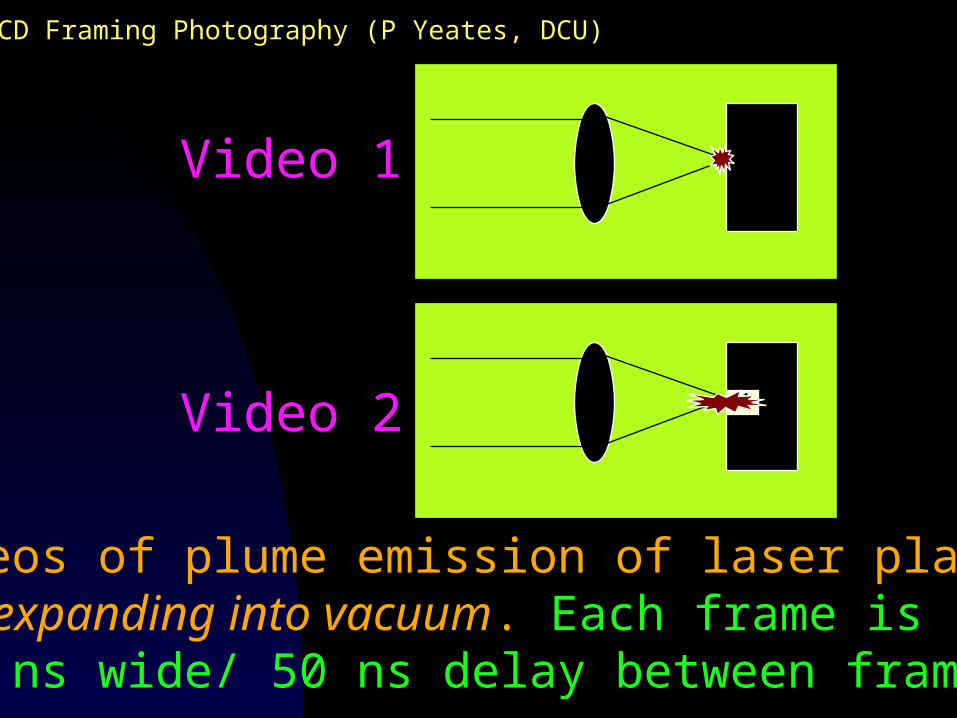
Videos of plume emission of laser plasmaexpanding into vacuum. Each frame is
10 ns wide/ 50 ns delay between frames
Video 1
Video 2
ICCD Framing Photography (P Yeates, DCU)
Video 1 - Laser Plasma formed on flat Al metal surface
QuickTime™ and aYUV420 codec decompressor
are needed to see this picture.
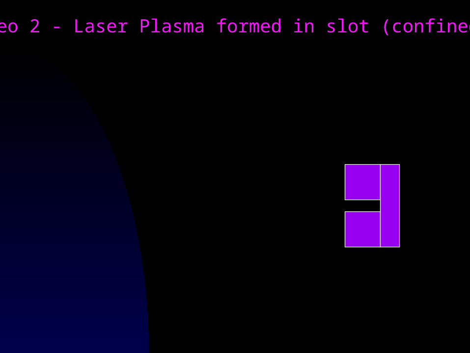
Video 2 - Laser Plasma formed in slot (confined)
QuickTime™ and aYUV420 codec decompressor
are needed to see this picture.
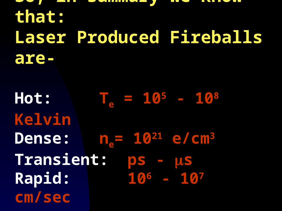
So, in summary we know that:Laser Produced Fireballs are-
Hot: Te = 105 - 108 KelvinDense: ne= 1021 e/cm3
Transient: ps - sRapid: 106 - 107 cm/sec
Dublin to Cork in 3 seconds !!!
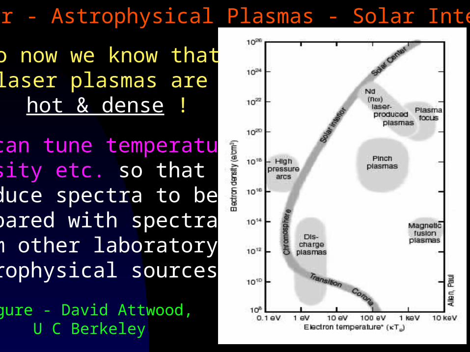
We can tune temperature, density etc. so that theyproduce spectra to be compared with spectra from other laboratory and astrophysical sources !!
So now we know that laser plasmas are
hot & dense !
Laser - Astrophysical Plasmas - Solar Interior
Figure - David Attwood, U C Berkeley
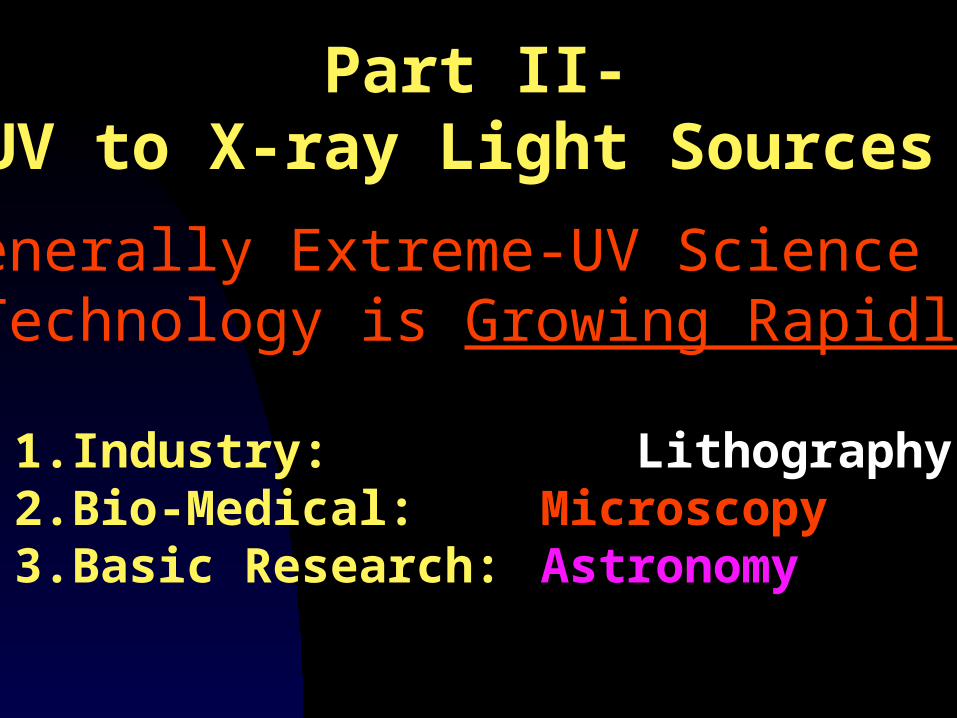
Part II-UV to X-ray Light Sources
Generally Extreme-UV Science & Technology is Growing Rapidly
1. Industry: Lithography2. Bio-Medical: Microscopy3. Basic Research: Astronomy
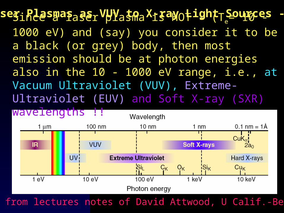
Since a laser plasma is HOT - (Te= 10 - 1000 eV) and (say) you consider it to be a black (or grey) body, then most emission should be at photon energies also in the 10 - 1000 eV range, i.e., at Vacuum Ultraviolet (VUV), Extreme-Ultraviolet (EUV) and Soft X-ray (SXR) wavelengths !!
Figure from lectures notes of David Attwood, U Calif.-Berkeley
Laser Plasmas as VUV to X-ray Light Sources - I
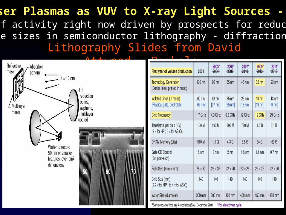
Lots of activity right now driven by prospects for reducing feature sizes in semiconductor lithography - diffraction limit
Lithography Slides from David Attwood - Berkeley
Laser Plasmas as VUV to X-ray Light Sources - II
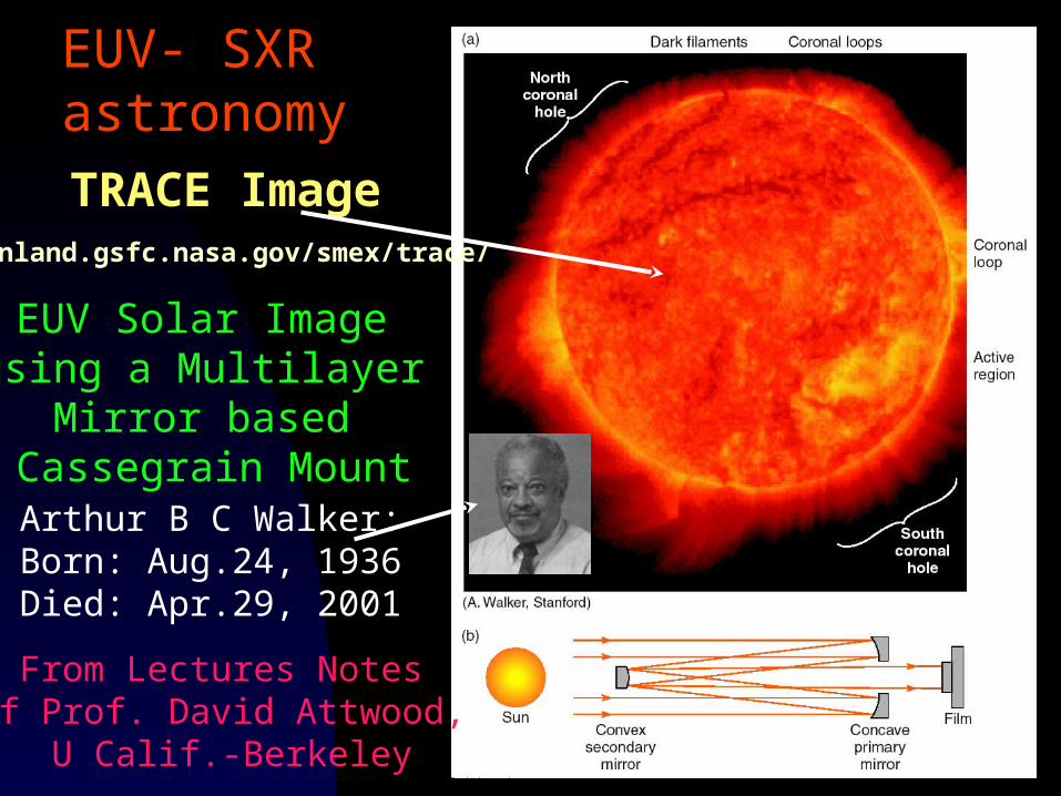
EUV Solar Image using a Multilayer
Mirror based Cassegrain Mount
From Lectures Notes of Prof. David Attwood,
U Calif.-Berkeley
TRACE Image
Arthur B C Walker:Born: Aug.24, 1936 Died: Apr.29, 2001
sunland.gsfc.nasa.gov/smex/trace/
EUV- SXR astronomy
But back to laser-plasma EUV Sources
Our Major Objective:
We want to probe matter with wavelength tuneable UV-SXR radiation so that we can study photoabsorption/ photo-ionization. Ergo we need a laser plasma source that emits a 'continuum' from the UV to the soft X-ray:
We need a table-top 'synchrotron'
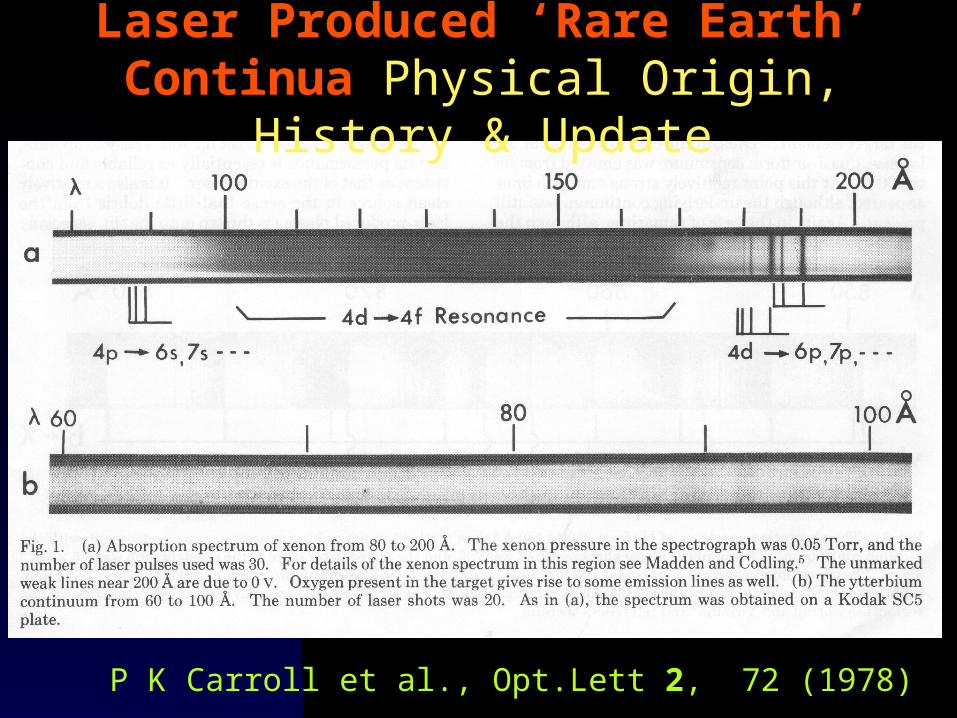
P K Carroll et al., Opt.Lett 2, 72 (1978)
Laser Produced ‘Rare Earth’ Continua Physical Origin, History & Update
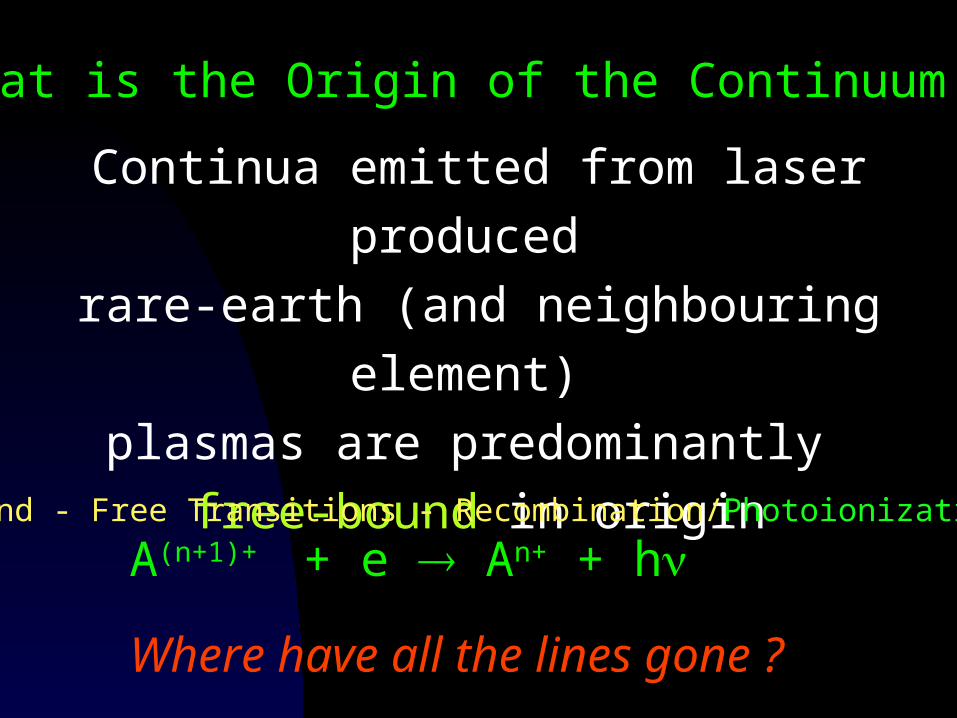
What is the Origin of the Continuum ?
Continua emitted from laser produced
rare-earth (and neighbouring element)
plasmas are predominantly
free-bound in origin
Where have all the lines gone ?
Bound - Free Transitions - Recombination/Photoionization*
A(n+1)+ + e An+ + h
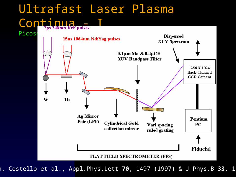
Ultrafast Laser Plasma Continua - IPicosecond LPLS (DCU, QUB & RAL, UK)
Meighan, Costello et al., Appl.Phys.Lett 70, 1497 (1997) & J.Phys.B 33, 1159 (2000)
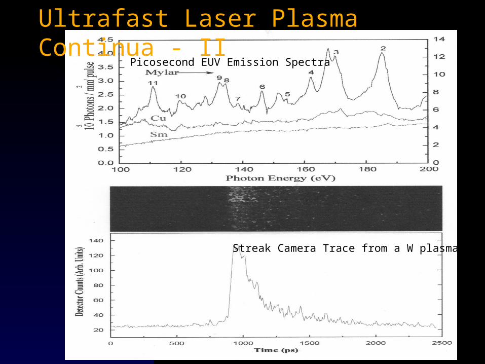
Streak Camera Trace from a W plasma
Picosecond EUV Emission Spectra
Ultrafast Laser Plasma Continua - II
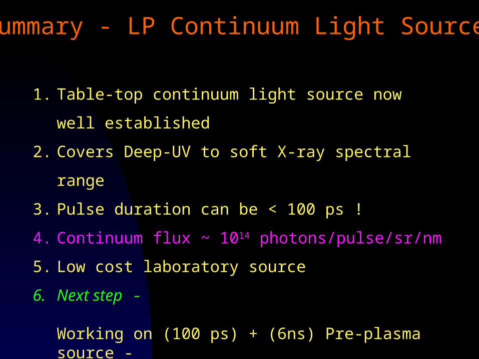
Summary - LP Continuum Light Sources
1. Table-top continuum light source now well established
2. Covers Deep-UV to soft X-ray spectral range
3. Pulse duration can be < 100 ps !
4. Continuum flux ~ 1014 photons/pulse/sr/nm
5. Low cost laboratory source
6. Next step -
Working on (100 ps) + (6ns) Pre-plasma source - we already see a flux gain of up to X4 with Cu-A Murphy et al., Proc SPIE, 4876, 1202 (2003)
Now we can probe matter with photoionizing radiation from this Fast-Pulsed, Laser Plasma Continuum Light Source
BUT !!!Laser plasmas are also are a source of atoms, ions, clusters, etc.
Ergo not only should we be able to develop laser plasmas into light sources but also into samples of atoms and ions to be probed.
Result - DUAL LASER PLASMA (DLP) PHOTO-ABSORPTION EXPERIMENTS
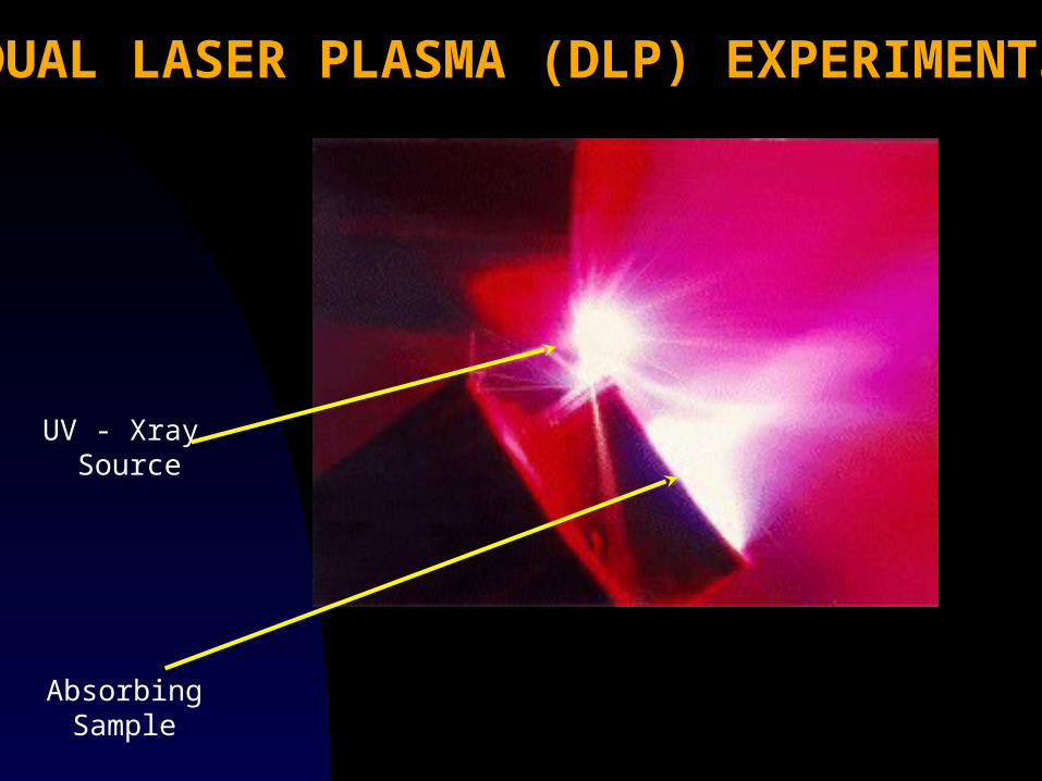
DUAL LASER PLASMA (DLP) EXPERIMENTS
UV - Xray Source
AbsorbingSample
Why Photoabsorption ?
Access to ground/ metastable state (Dark) species
Electric dipole excitation yields tractable spectra
Photoabsorption/ ionization data are relevant to- Astrophysical spectra and models Laboratory plasma modelling Fundamental many-body theory X-ray laser schemes ICF
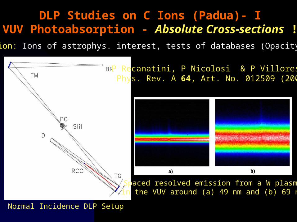
DLP Studies on C Ions (Padua)- IVUV Photoabsorption - Absolute Cross-sections !
Normal Incidence DLP Setup
P Recanatini, P Nicolosi & P Villoresi, Phys. Rev. A 64, Art. No. 012509 (2001)
Spaced resolved emission from a W plasmain the VUV around (a) 49 nm and (b) 69 nm
Motivation: Ions of astrophys. interest, tests of databases (Opacity, etc.)
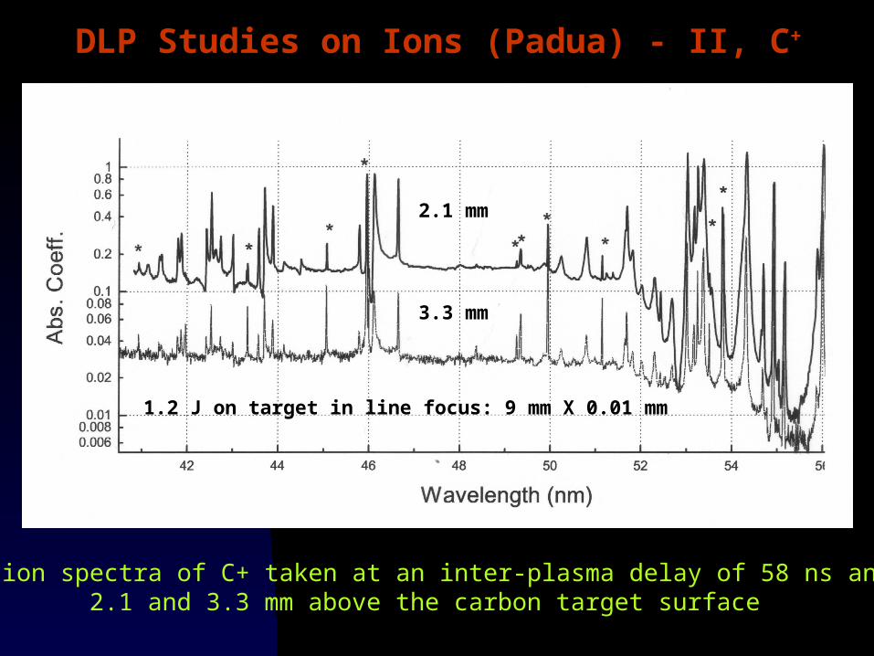
DLP Studies on Ions (Padua) - II, C+
Absorption spectra of C+ taken at an inter-plasma delay of 58 ns and at 2.1 and 3.3 mm above the carbon target surface
2.1 mm
3.3 mm
1.2 J on target in line focus: 9 mm X 0.01 mm
Work centres low-Z ions of astrophysical interest
All isonuclear sequences of Be, B and C measured.
Designed and built DLP systems to work from VUV to Soft X-ray (Carbon K)
Have determined absolute photoabsorption cross sections using DLP
Group have designed and built many VUV and EUVspectrometers and optical systems for NASA
Summary - Padua

DublinHave published upwards of 100 papers on DLP photoabsorption experiments on selected atoms and ions from all rows of the periodic table.
Motivation - almost always exploration of some 'quirk' of the photoionization process in a many electron atom !
Recent Examples“Trends in Autoionization of Rydberg States converging to the 4s Threshold in the Kr-Rb+-Sr2+ Series: Experiment and Theory”Amit Neogi, John T Costello et al., Phys.Rev.A 67, Art. No. 042707 (2003)
“EUV Ionising Radiation and Atoms and Ions: Dual Laser Plasma Investigations”,
E T Kennedy, J T Costello, J-P Mosnier and P van Kampen, Radiat. Phys. Chem. (in press 2004)

BUT NO TIME TO TALK ABOUT THAT RIGHT NOW BECAUSE I WANT TO TALK ABOUT.....................
VUV Photoabsorption Imaging
Part III
Collaboration between DCU & Univ. PaduaKey paper:J Hirsch, E Kennedy, J T Costello, L Poletto & P Nicolosi Rev.Sci. Instrum. 74, 2992 (2003)
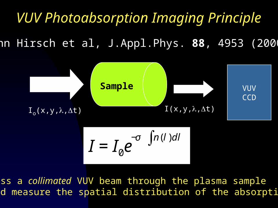
VUV Photoabsorption Imaging Principle
Pass a collimated VUV beam through the plasma sample and measure the spatial distribution of the absorption.
Io(x,y,,t)
Sample
I(x,y,,t)
VUVCCD
€
I =I0e−σ n(l )dl∫
John Hirsch et al, J.Appl.Phys. 88, 4953 (2000)
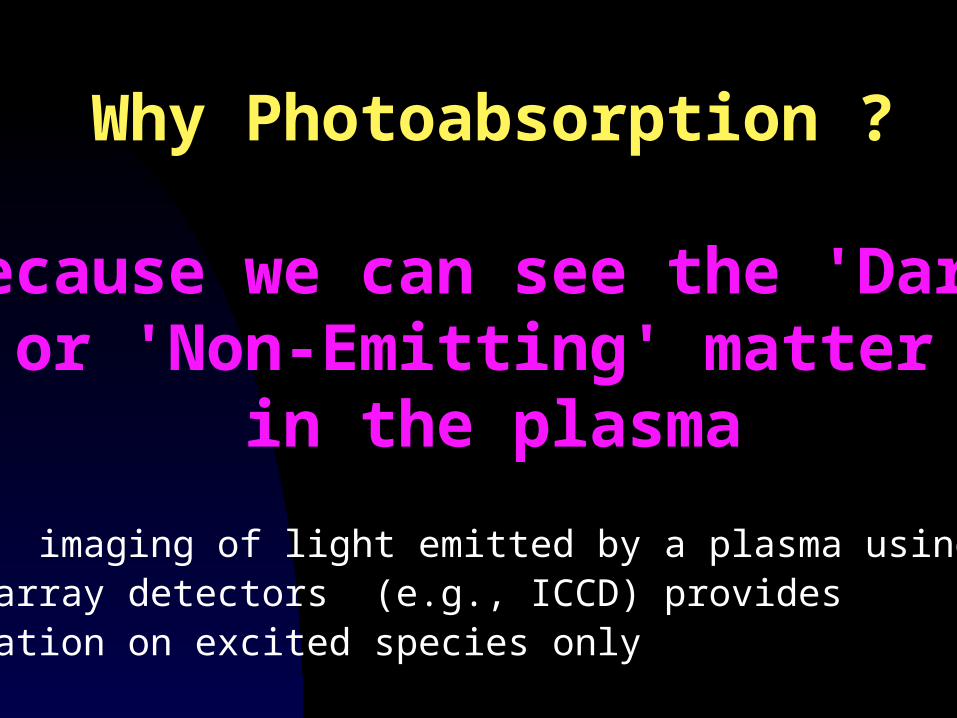
Why Photoabsorption ?
Because we can see the 'Dark'or 'Non-Emitting' matter
in the plasma
Direct imaging of light emitted by a plasma using gated array detectors (e.g., ICCD) provides information on excited species only
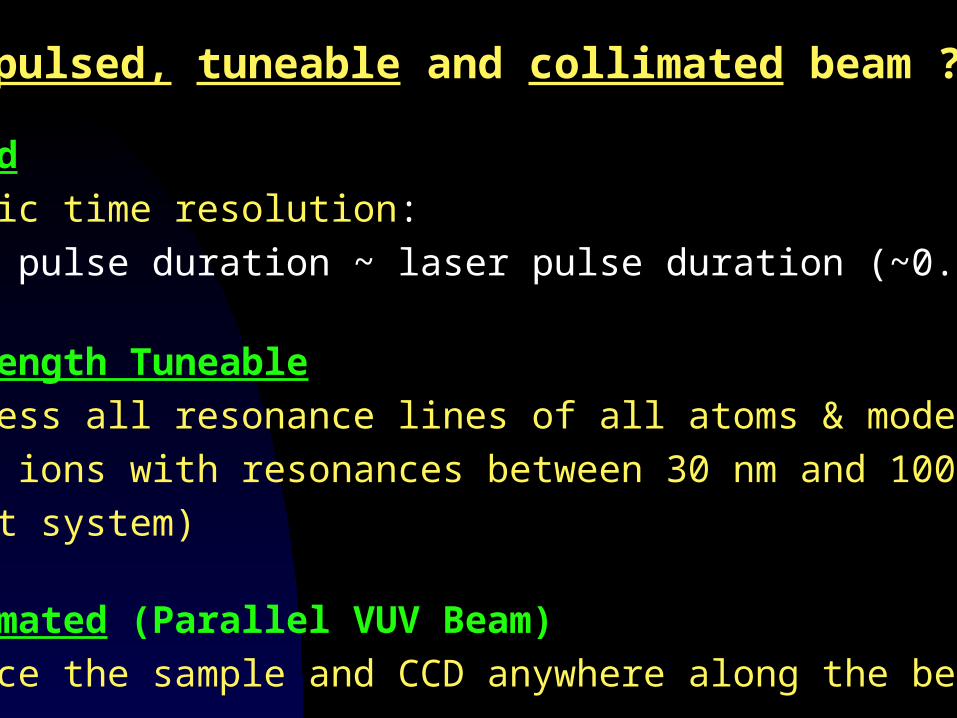
Why a pulsed, tuneable and collimated beam ?
• Pulsed
Automatic time resolution:
the VUV pulse duration ~ laser pulse duration (~0.1-30 ns)
• Wavelength Tuneable
Can access all resonance lines of all atoms & moderately
charged ions with resonances between 30 nm and 100 nm
(present system)
• Collimated (Parallel VUV Beam)
Can place the sample and CCD anywhere along the beam
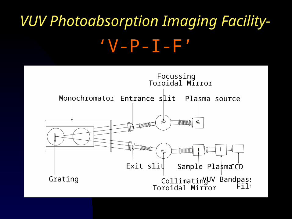
VUV Photoabsorption Imaging Facility-
‘V-P-I-F’
Monochromator
Grating
Exit slit
Entrance slit
FocussingToroidal Mirror
Plasma source
Collimating Toroidal Mirror
Sample Plasma CCD
VUV Bandpass Filter
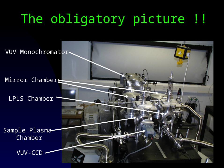
The obligatory picture !!
VUV Monochromator
Mirror Chambers
LPLS Chamber
Sample Plasma Chamber
VUV-CCD
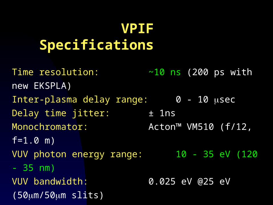
VPIF Specifications
Time resolution: ~10 ns (200 ps with new EKSPLA)
Inter-plasma delay range: 0 - 10 sec
Delay time jitter: ± 1ns
Monochromator: Acton™ VM510 (f/12, f=1.0 m)
VUV photon energy range: 10 - 35 eV (120 - 35 nm)
VUV bandwidth: 0.025 eV @25 eV (50m/50m slits)
~0.05 nm @ 50 nm
Detector: Andor™ BN-CCD,
1024 x 2048/13 m x 13 m pixels
Spatial resolution: ~120 m (H) x 150 m (V)
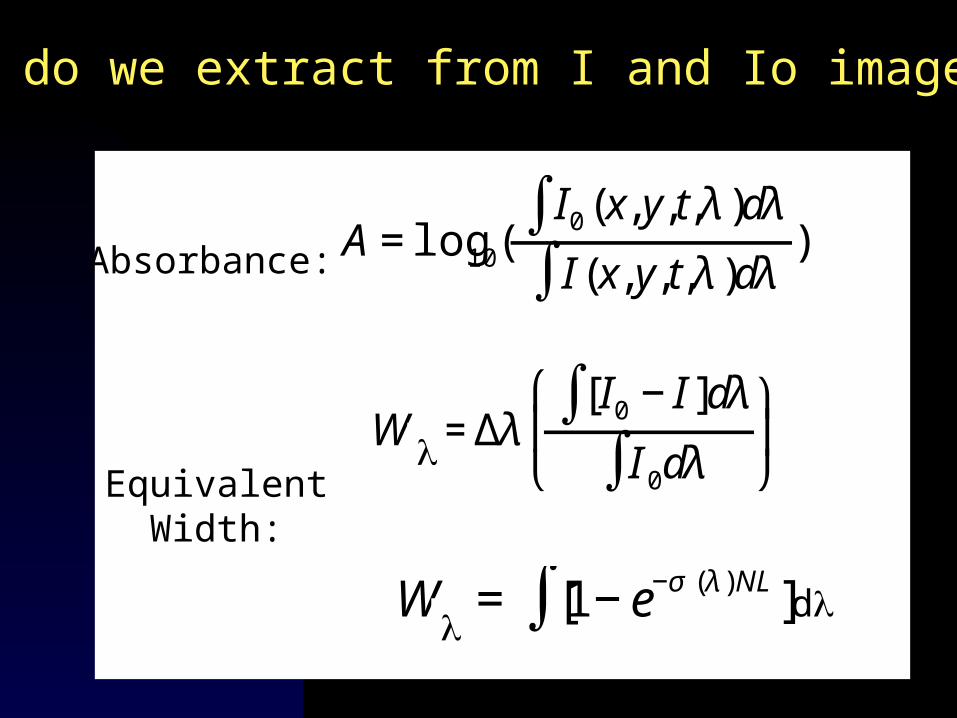
What do we extract from I and Io images ?
€
A=log10(I0(x,y,t,λ)dλ∫I (x,y,t,λ)dλ∫ )Absorbance:
€
WE = [1−e−σ (λ)NL]∫
€
WE =Δλ[I0 −I ]dλ∫I 0dλ∫
⎛
⎝ ⎜
⎞
⎠ ⎟
EquivalentWidth:
d

Tune system to 3 unique resonances
Ca: 3p64s2 (1S) + (31.4 eV) 3p54s23d (1P)
Ca+: 3p64s (2S) + (33.2 eV) 3p54s23d (2P)
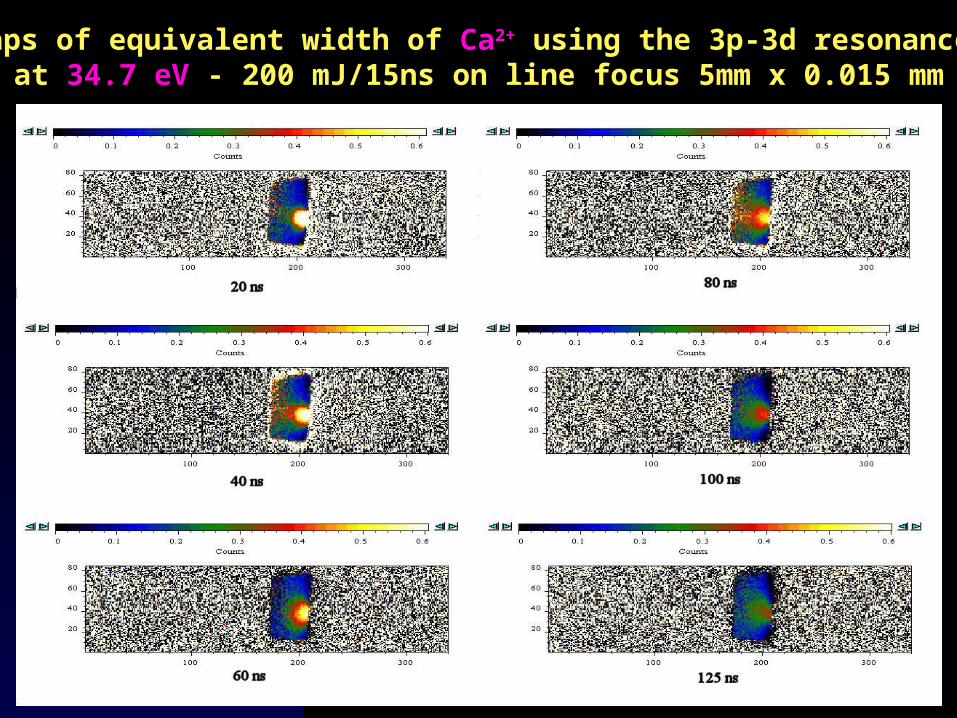
Ca2+: 3p6 (1S) + (34.7 eV) 3p53d (1P)
Time resolved W maps of Ca plume species
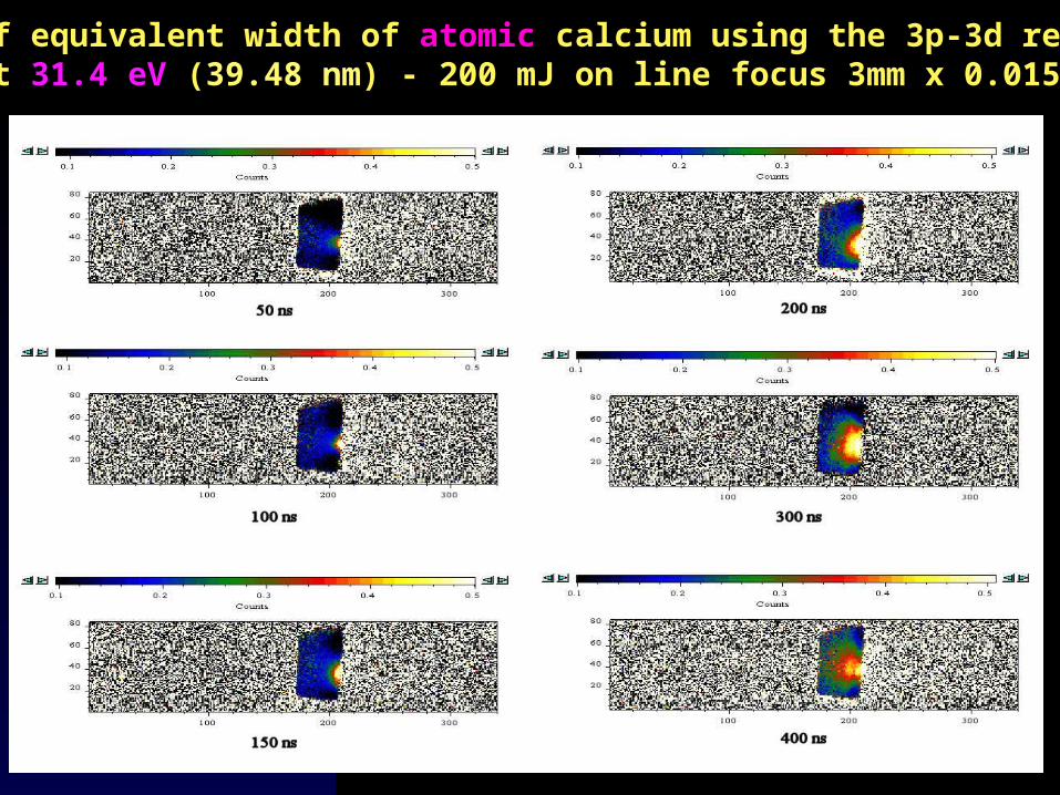
Maps of equivalent width of atomic calcium using the 3p-3d resonance at 31.4 eV (39.48 nm) - 200 mJ on line focus 3mm x 0.015 mm
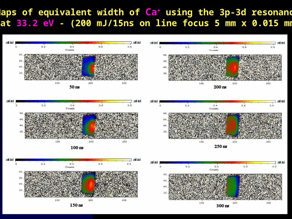
Maps of equivalent width of Ca+ using the 3p-3d resonance at 33.2 eV - (200 mJ/15ns on line focus 5 mm x 0.015 mm)
Maps of equivalent width of Ca2+ using the 3p-3d resonance at 34.7 eV - 200 mJ/15ns on line focus 5mm x 0.015 mm
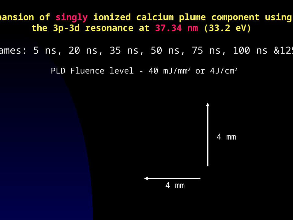
Expansion of singly ionized calcium plume component using the 3p-3d resonance at 37.34 nm (33.2 eV)
QuickTime™ and aGIF decompressorare needed to see this picture.
7 frames: 5 ns, 20 ns, 35 ns, 50 ns, 75 ns, 100 ns &125 ns
4 mm
4 mm
PLD Fluence level - 40 mJ/mm2 or 4J/cm2
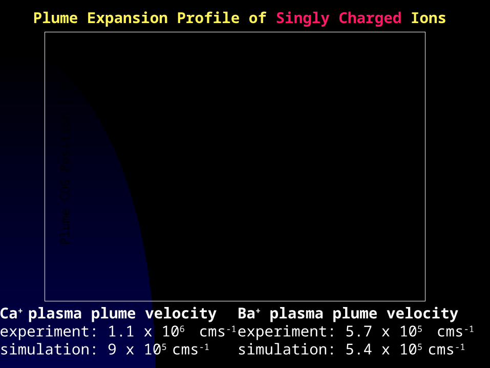
Plume Expansion Profile of Singly Charged Ions
Ca+ plasma plume velocityexperiment: 1.1 x 10⁶ cms-1
simulation: 9 x 10⁵ cms-1
Ba+ plasma plume velocityexperiment: 5.7 x 10⁵ cms-1
simulation: 5.4 x 10⁵ cms-1
Delay (ns)
Plu
me
CO
G P
ositi
on (
cm)
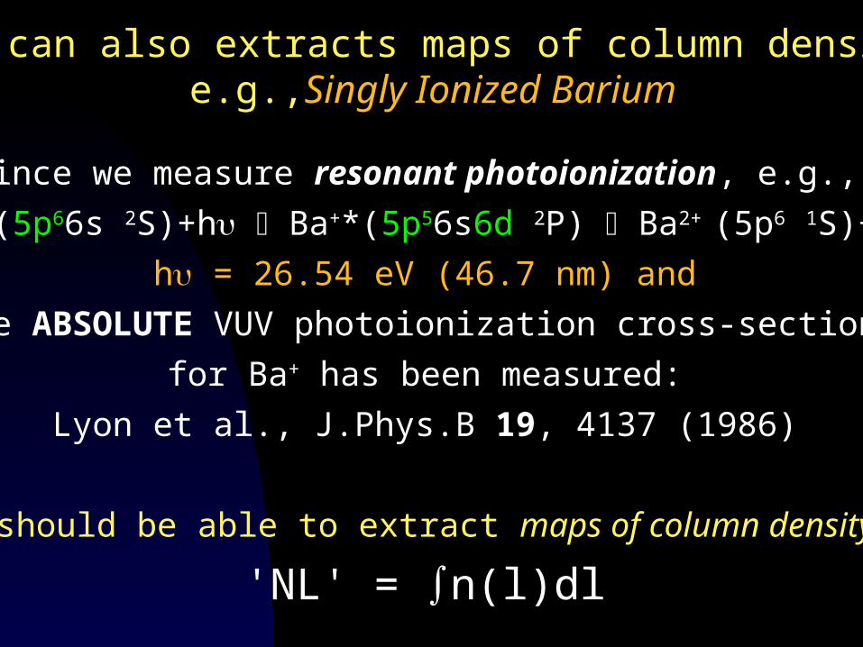
You can also extracts maps of column density,e.g.,Singly Ionized Barium
Since we measure resonant photoionization, e.g.,
Ba+(5p66s 2S)+h Ba+*(5p56s6d 2P) Ba2+ (5p6 1S)+e-
h = 26.54 eV (46.7 nm) and
the ABSOLUTE VUV photoionization cross-section
for Ba+ has been measured:
Lyon et al., J.Phys.B 19, 4137 (1986)
We should be able to extract maps of column density -
'NL' = ∫n(l)dl
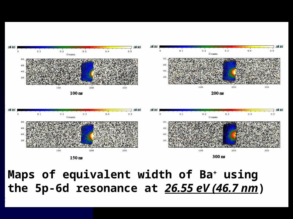
Maps of equivalent width of Ba+ using the 5p-6d resonance at 26.55 eV (46.7 nm)
dl
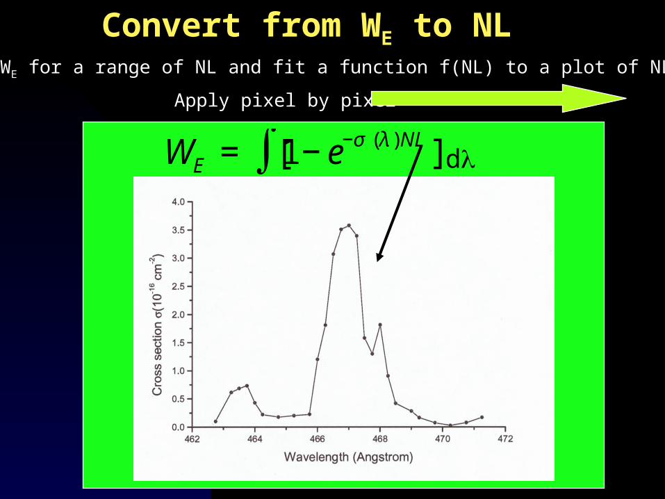
Convert from WE to NLCompute WE for a range of NL and fit a function f(NL) to a plot of NL .vs. W
Apply pixel by pixel
€
WE = [1−e−σ (λ)NL]∫ d
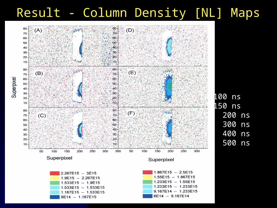
Result - Column Density [NL] Maps
(A) 100 ns (B) 150 ns(C) 200 ns(D) 300 ns(E) 400 ns(F) 500 ns
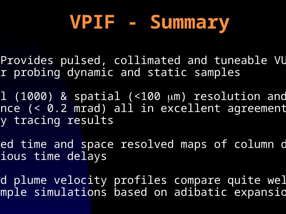
VPIF - Provides pulsed, collimated and tuneable VUV beam for probing dynamic and static samples
Spectral (1000) & spatial (<100 m) resolution anddivergence (< 0.2 mrad) all in excellent agreement with ray tracing results
Extracted time and space resolved maps of column density for various time delays
Measured plume velocity profiles compare quite well with simple simulations based on adibatic expansion
VPIF - Summary
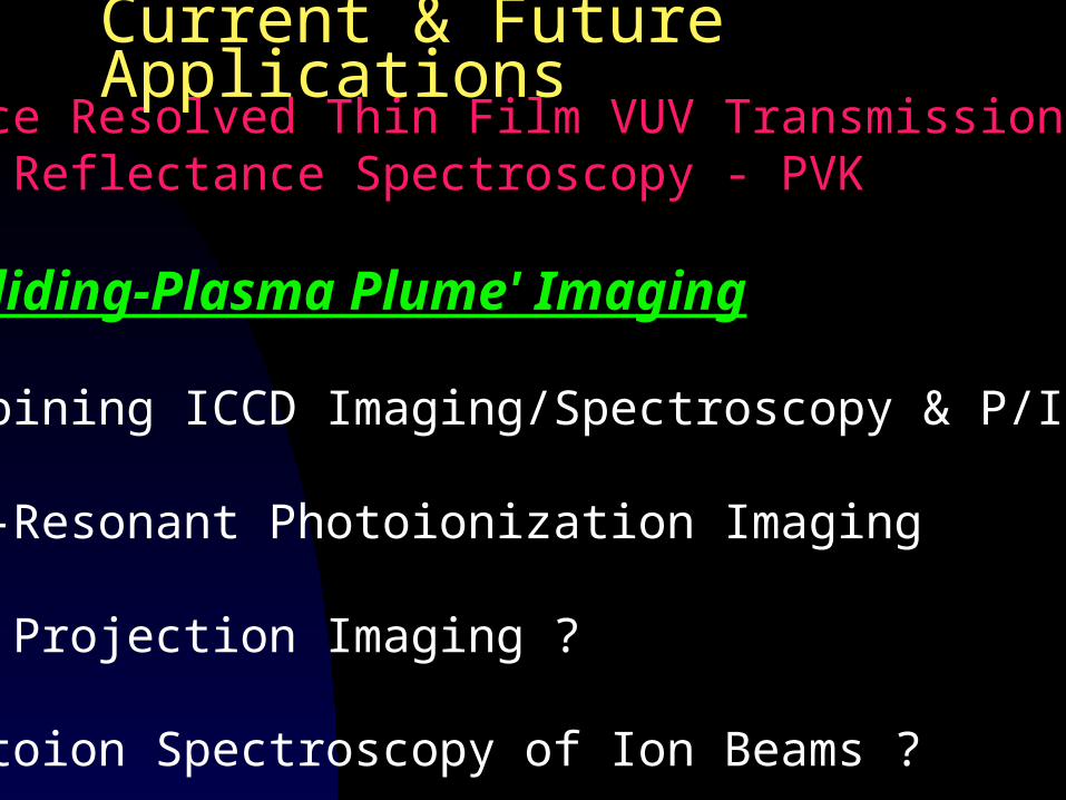
Space Resolved Thin Film VUV Transmission and Reflectance Spectroscopy - PVK
‘Colliding-Plasma Plume' Imaging
Combining ICCD Imaging/Spectroscopy & P/Imag Non-Resonant Photoionization Imaging
VUV Projection Imaging ?
Photoion Spectroscopy of Ion Beams ?
Current & Future Applications
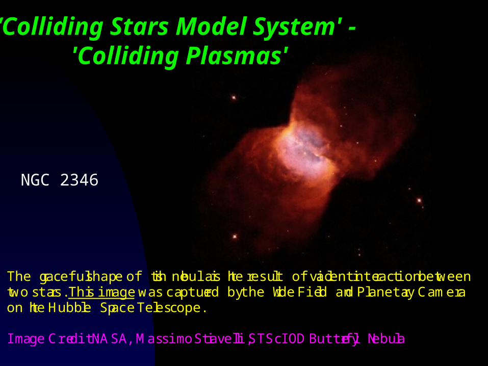
‘Colliding Stars Model System' - 'Colliding Plasmas'
The graceful shape of this nebula is the result of a violent interaction betweentwo stars. This image was captured by the Wide Field and Planetary Cameraon the Hubble Space Telescope.
Image Credit: NASA, Massimo Stiavelli, STScI ODButterfly Nebula
NGC 2346
First and very preliminary testson colliding plasma imaging with
the VPIF
QuickTime™ and aGIF decompressor
are needed to see this picture.
Colliding Plasmas on Flat Target
Colliding 'Opposing' Plasmas
QuickTime™ and aGIF decompressor
are needed to see this picture.
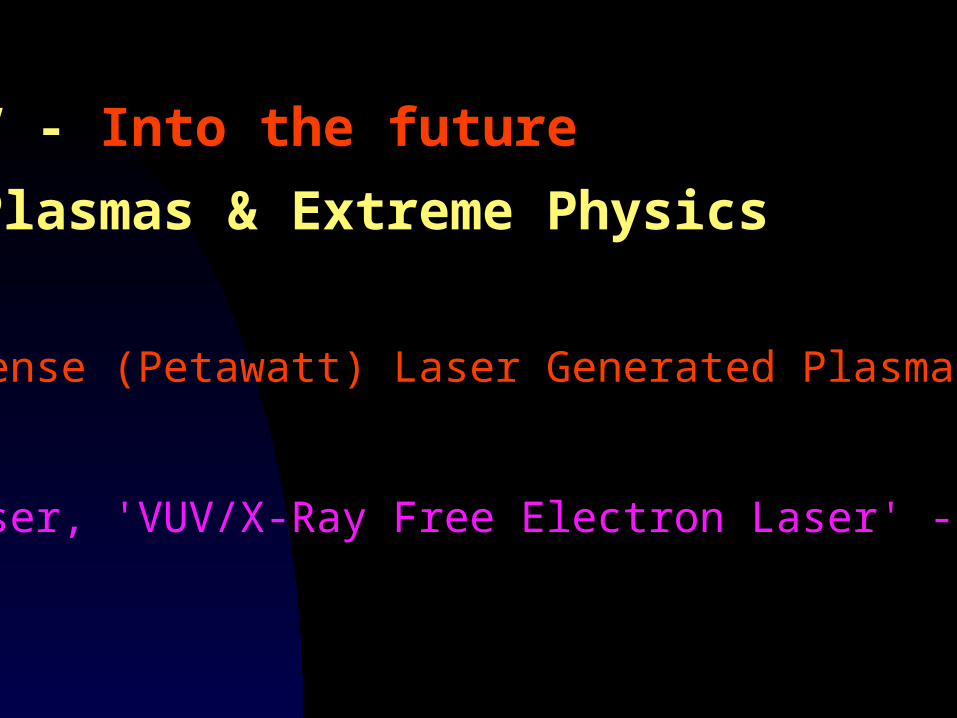
Part IV - Into the future
Laser Plasmas & Extreme Physics
Ultraintense (Petawatt) Laser Generated Plasmas - RAL
A New Laser, 'VUV/X-Ray Free Electron Laser' - DESY-FEL
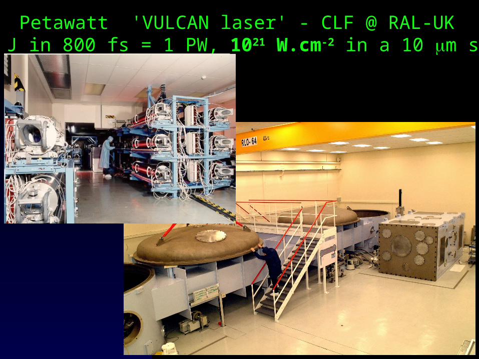
Petawatt 'VULCAN laser' - CLF @ RAL-UK800 J in 800 fs = 1 PW, 1021 W.cm-2 in a 10 m spot
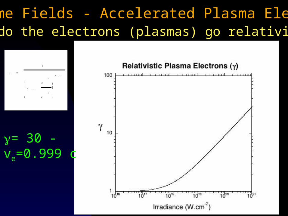
Extreme Fields - Accelerated Plasma ElectronsWhen do the electrons (plasmas) go relativistic ?
€
=
1
1 −
v
2
c
2
⎛
⎝
⎜ ⎞
⎠
⎟
1 / 2
= 30 - ve=0.999 c
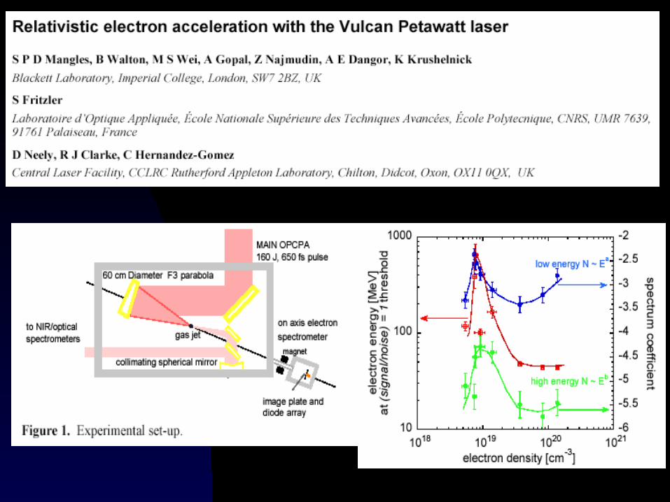
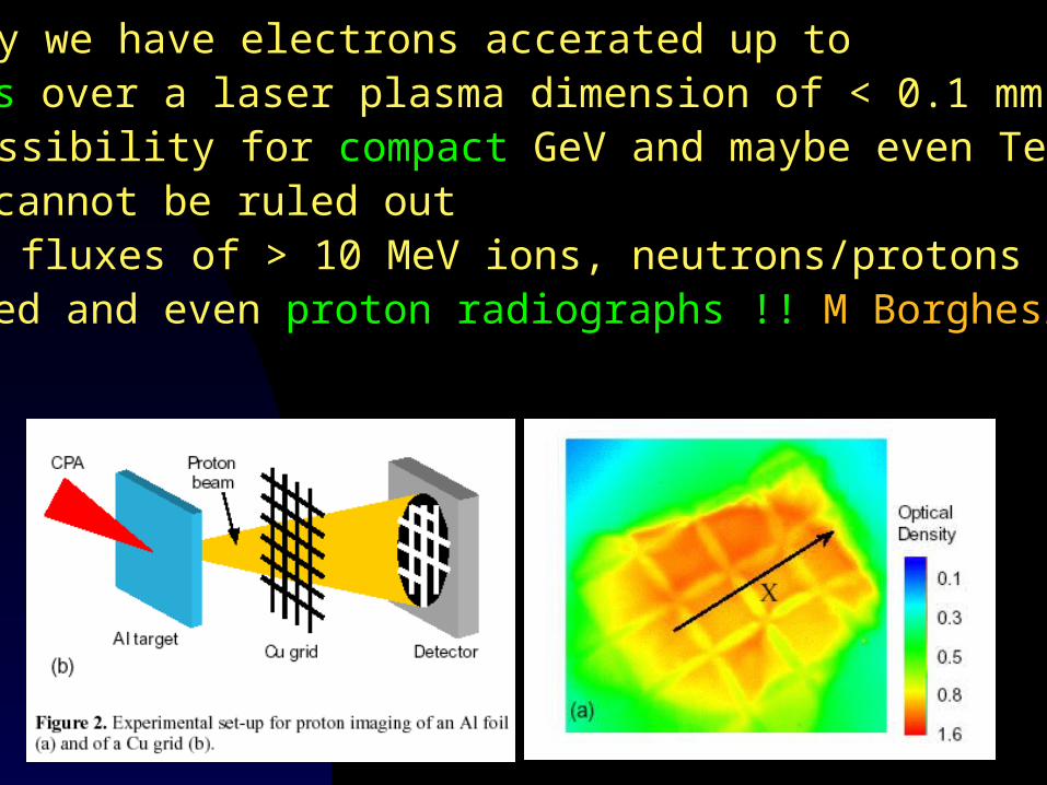
1. So already we have electrons accerated up toGeV energies over a laser plasma dimension of < 0.1 mm2. So the possibility for compact GeV and maybe even TeVaccerators cannot be ruled out3. Also high fluxes of > 10 MeV ions, neutrons/protons have been produced and even proton radiographs !! M Borghesi (QUB)
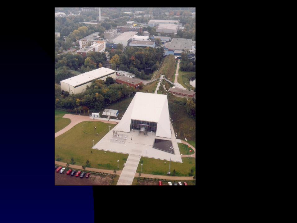
Free Electron Laser at Hasylab, DESY, Hamburg
'Laser-like' radiation in the VUV and EUV
And Finally !!!!!!
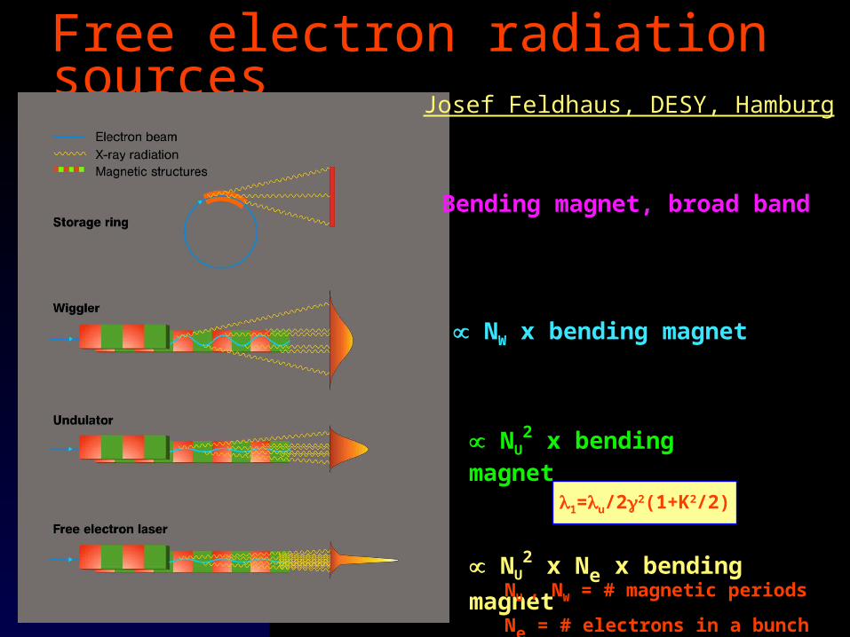
Free electron radiation sources
Bending magnet, broad band
NW x bending magnet
NU2 x bending magnet
NU2 x Ne x bending magnet
NU , NW = # magnetic periods
Ne = # electrons in a bunch
1=u/22(1+K2/2)
Josef Feldhaus, DESY, Hamburg
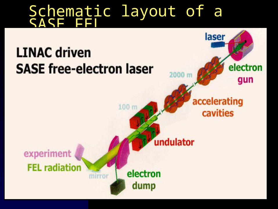
Schematic layout of a SASE FEL
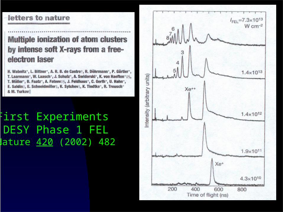
First Experiments DESY Phase 1 FELNature 420 (2002) 482
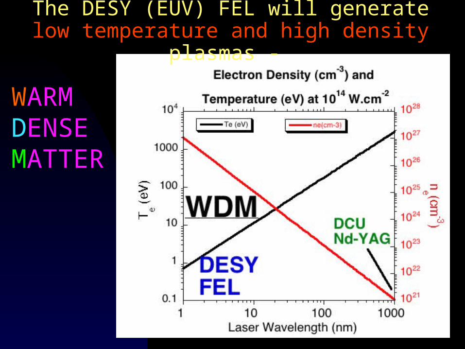
The DESY (EUV) FEL will generate low temperature and high density plasmas -
WARM DENSE MATTER
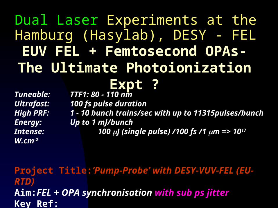
Dual Laser Experiments at the Hamburg (Hasylab), DESY - FEL
EUV FEL + Femtosecond OPAs- The Ultimate Photoionization Expt ?
Tuneable: TTF1: 80 - 110 nm Ultrafast: 100 fs pulse durationHigh PRF: 1 - 10 bunch trains/sec with up to 11315pulses/bunchEnergy: Up to 1 mJ/bunchIntense: 100 J (single pulse) /100 fs /1 m => 1017 W.cm-2
Project Title:‘Pump-Probe’ with DESY-VUV-FEL (EU-RTD)Aim:FEL + OPA synchronisation with sub ps jitter Key Ref: http://tesla.desy.de/new_pages/TDR_CD/start.htmlPersonnel:DESY, MBI, CLPR-DCU, LURE, LLC, BESSY
synchronization
790-830 nm100 fs
SHG
Nd:YLF pulse train laser(identical to cathode laser)
pump beam524 nm10 ps
Ti-Sa oscillator
LBO crystal
Non-linear crystalOPA
Amplified beamFilterSynchronization
with RF/FELPulse
stretcher
Pulsecompressor
10 ps790-830 nm
150 fs
weaktunablefemtosecond
high-power1048 nm10 ps
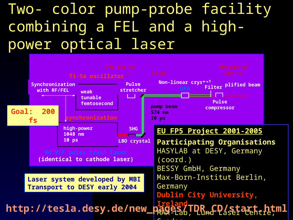
Laser system developed by MBITransport to DESY early 2004
Two- color pump-probe facility combining a FEL and a high-power optical laser
EU FP5 Project 2001-2005
Participating OrganisationsHASYLAB at DESY, Germany (coord.)BESSY GmbH, GermanyMax-Born-Institut Berlin, GermanyDublin City University, IrelandMAX-Lab, Lund Laser Centre, SwedenCNRS/LURE Orsay, France
Goal: 200 fs
http://tesla.desy.de/new_pages/TDR_CD/start.html
Two- color pump-probe facility combining a FEL and a high-power optical laser
We will be able to study intense laser-matter interaction at ultrashort laser wavelengths (1nm) for the first time
We will be able to do new photoionization experiments on laser generated plasmas (WDM), clusters etc. with femto-second time resolution
The unprecedented intensity will permit detection and measurements of weakly absorbing species
We will be able to do non-linear optics (e.g., harmonic generation, IR + EUV frequency mixing) in the EUV and X-ray for the first time
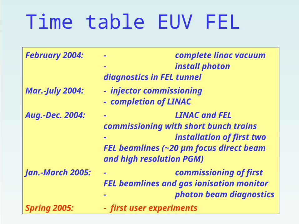
Time table EUV FEL
February 2004: - complete linac vacuum- install photon diagnostics in FEL tunnel
Mar.-July 2004: - injector commissioning- completion of LINAC
Aug.-Dec. 2004: - LINAC and FEL commissioning with short bunch trains- installation of first two FEL beamlines (~20 µm focus direct beam and high resolution PGM)
Jan.-March 2005: - commissioning of first FEL beamlines and gas ionisation monitor- photon beam diagnostics
Spring 2005: - first user experiments
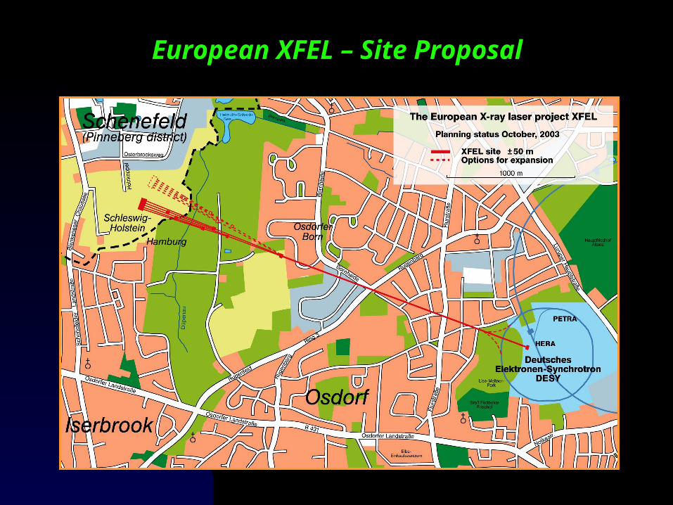
European XFEL – Site Proposal
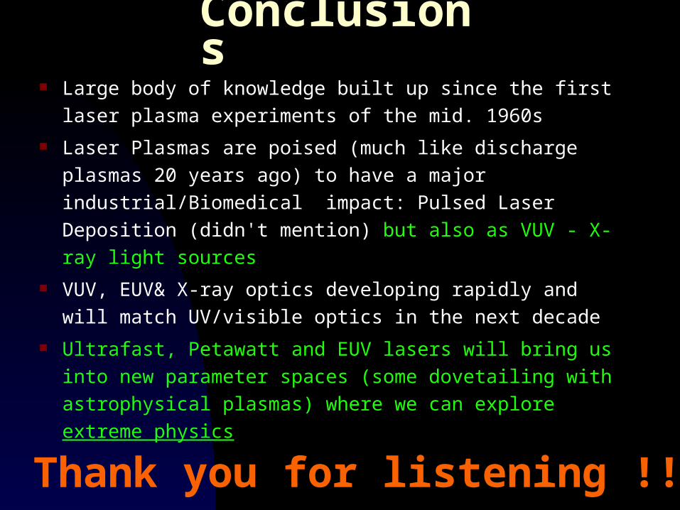
Thank you for listening !!!
Conclusions Large body of knowledge built up since the first laser
plasma experiments of the mid. 1960s
Laser Plasmas are poised (much like discharge plasmas
20 years ago) to have a major industrial/Biomedical
impact: Pulsed Laser Deposition (didn't mention) but
also as VUV - X-ray light sources
VUV, EUV& X-ray optics developing rapidly and will
match UV/visible optics in the next decade
Ultrafast, Petawatt and EUV lasers will bring us into new
parameter spaces (some dovetailing with astrophysical
plasmas) where we can explore extreme physics