joint angles calculation lei zhou and xiaolin li october 28, 2014
TRANSCRIPT

Joint Angles Calculation
Lei Zhou and Xiaolin Li October 28, 2014

Outline
• Joint Coordinate System (JCS) Concept Example
• Euler’s Angle
• Helical Method

Joint Coordinate System----concept
The joint coordinate system(JCS) is defined by two
independent body-fixed axes and the common perpendicular.
Joint Coordinate System----concept
The Joint Coordinate System (JCS) was proposed by Grood and Suntay (1983) to encourage the use of clinically relevant models.

Joint Coordinate System----concept
Joint Coordinate System is composed of the two body fixed axes, e1 and e3 and their mutual perpendicular, e2.
Click View then Header and Footer to change this footer
Example---- Hip joint
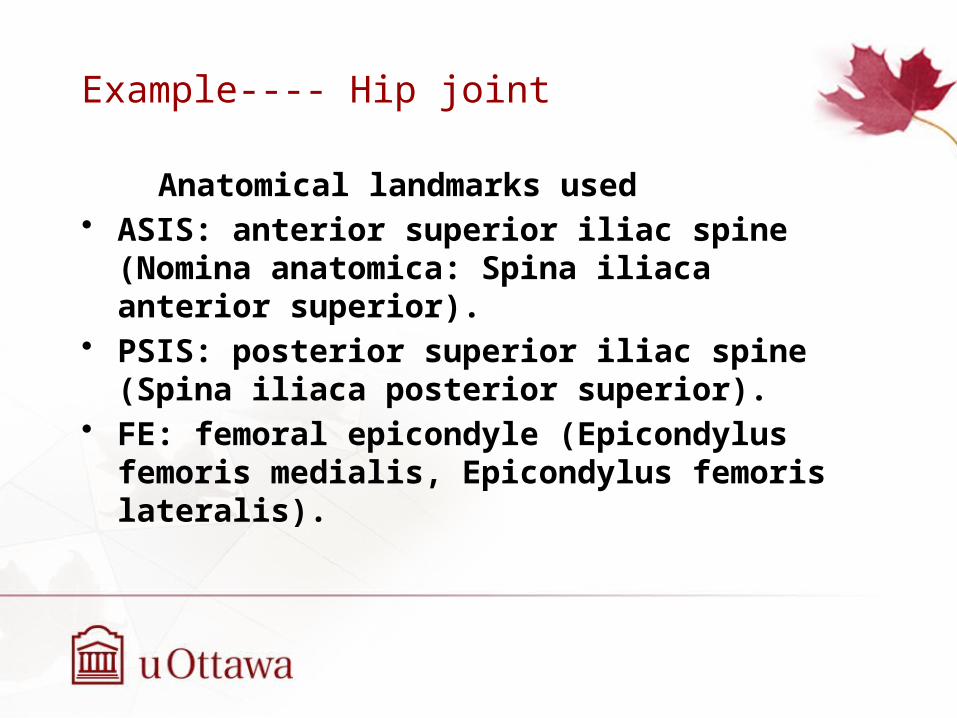
Anatomical landmarks used• ASIS: anterior superior iliac spine (Nomina anatomica:
Spina iliaca anterior superior).• PSIS: posterior superior iliac spine (Spina iliaca
posterior superior).• FE: femoral epicondyle (Epicondylus femoris medialis,
Epicondylus femoris lateralis).

Example
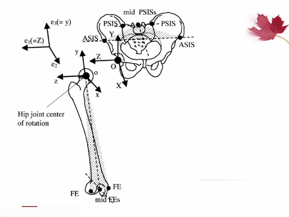
Where is the “O” The common origin of both axis systems is the point of
reference for the linear translation occurring in the joint, at its initial neutral position.

ExamplePelvic coordinate system—XYZ
• O: The origin coincident with the right hip center of rotation.
• Z: The line parallel to a line connecting the right and left ASISs, and pointing to the right.
• X: The line parallel to a line lying in the plane defined by the two ASISs and the midpoint of the two PSISs, orthogonal to the Z-axis, and pointing anteriorly.
• Y: The line perpendicular to both X and Z, pointing cranially.

ExampleFemoral coordinate system—xyz
• o: The origin coincident with the right hip center of rotation, coincident with that of the pelvic coordinate system (O) in the neutral configuration.
• y: The line joining the midpoint between the medial and lateral FEs and the origin, and pointing cranially.
• z: The line perpendicular to the y-axis, lying in the plane defined by the origin and the two FEs, pointing to the right.
• x: The line perpendicular to both y- and z-axis, pointing anteriorly
ExampleJCS and motion for the right hip joint
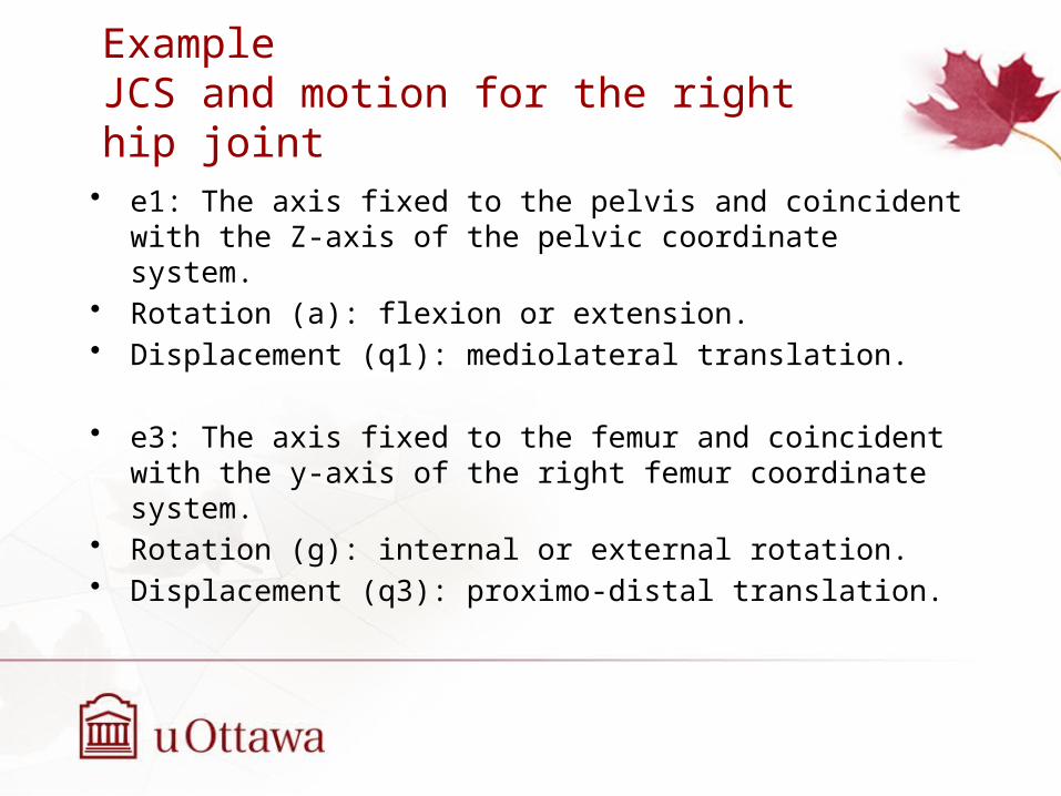
• e1: The axis fixed to the pelvis and coincident with the Z-axis of the pelvic coordinate system.
• Rotation (a): flexion or extension.• Displacement (q1): mediolateral translation.
• e3: The axis fixed to the femur and coincident with the y-axis of the right femur coordinate system.
• Rotation (g): internal or external rotation.• Displacement (q3): proximo-distal translation.

ExampleJCS and motion for the right hip joint
• e2: The floating axis, the common axis perpendicular to e1 and e3.• Rotation (b): adduction or abduction.• Displacement (q2): antero-posterior translation.

Euler’s Angle
Definition and Function
a) Describe the orientation of a rigid body
b) Used to represent the orientation of a frame of reference relative to another.
c) Represent a sequence of three elemental rotations
The elemental rotations can either occur about the axes of the fixed coordinate system (global coordinate system) or about the axes of a rotating coordinate system
(local coordinate system).

Euler’s Angles
Characters Specific orders, the sequence is not actual path of motion taken to
arrive at that position Different rotation orders can lead to different orientations
ex: book on a desk; The book will no doubt be oriented in space differently after each set of rotation Twelve possible sequences of rotation axes
Euler angles (z-x-z, x-y-x, y-z-y, z-y-z, x-z-x, y-x-y)
Cardan angles (x-y-z, y-z-x, z-x-y, x-z-y, z-y-x, y-x-z)

Euler angles in biomechanics
Purpose
A method used to describe three dimension motion of a joint
General sequence The first rotation is defined relative to an axis oriented in the global
coordinate system. The third is defined with regard to an axis fixed within the rotating
body. (Local coordinate system). The second is performed relative to the floating axis, which is always
orthogonal to both the first and third axis.

A gymnast performation
Precession The first rotation takes place relative to an axis defined in the global reference system.
Tilt Floating axis: The axis of tilt is not fixed with regard to both the global reference frame and the local reference frame.
SpinRotates around its longitudinal axis:fixed in the body.

Common Sequence in biomechanics studies
XYZ sequence
a) X is the flexion/extension in sagittal plane
b) Y is the abduction/adduction
c) Z is the axial (internal/external) rotation
Sinclair J, Taylor P J, Edmundson C J, et al. Influence of the helical and six available Cardan sequences on 3D
ankle joint kinematic parameters[J]. Sports Biomechanics, 2012, 11(3): 430-437.
The second and the third rotations are about local axes transformed by previous rotations. Ex. Xy’x’’Why do we use this sequence? XYZ sequence is associated with minimal planar crosstalk and as such itsuse is encouraged.
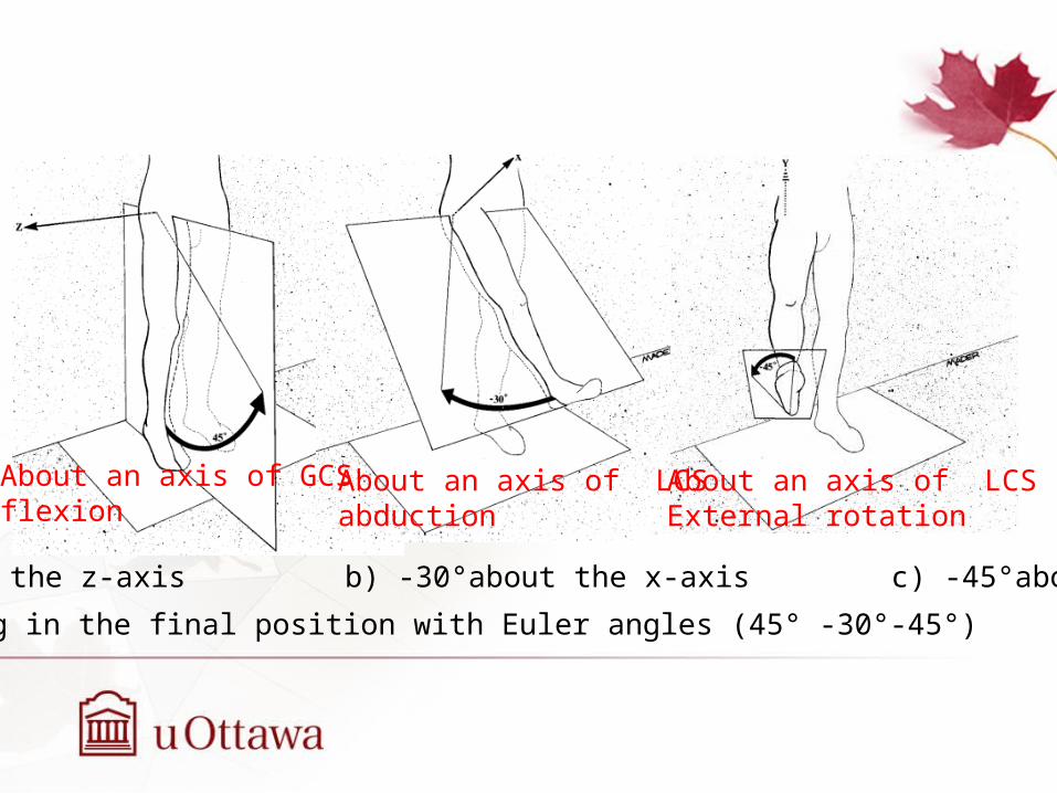
a) 45° about the z-axis b) -30°about the x-axis c) -45°about the y-axis
The leg in the final position with Euler angles (45° -30°-45°)
About an axis of GCSflexion
About an axis of LCSabduction
About an axis of LCSExternal rotation

Helical angles
Also a method to describe three dimension motions A screw axis/helical axis: a line that is simultaneously the axis of
rotation and the line along which translation of a body occurs. Chasles’ Theorem: any rigid-body motion can be obtained as the
rotation around an axis, and a translation parallel to the screw.
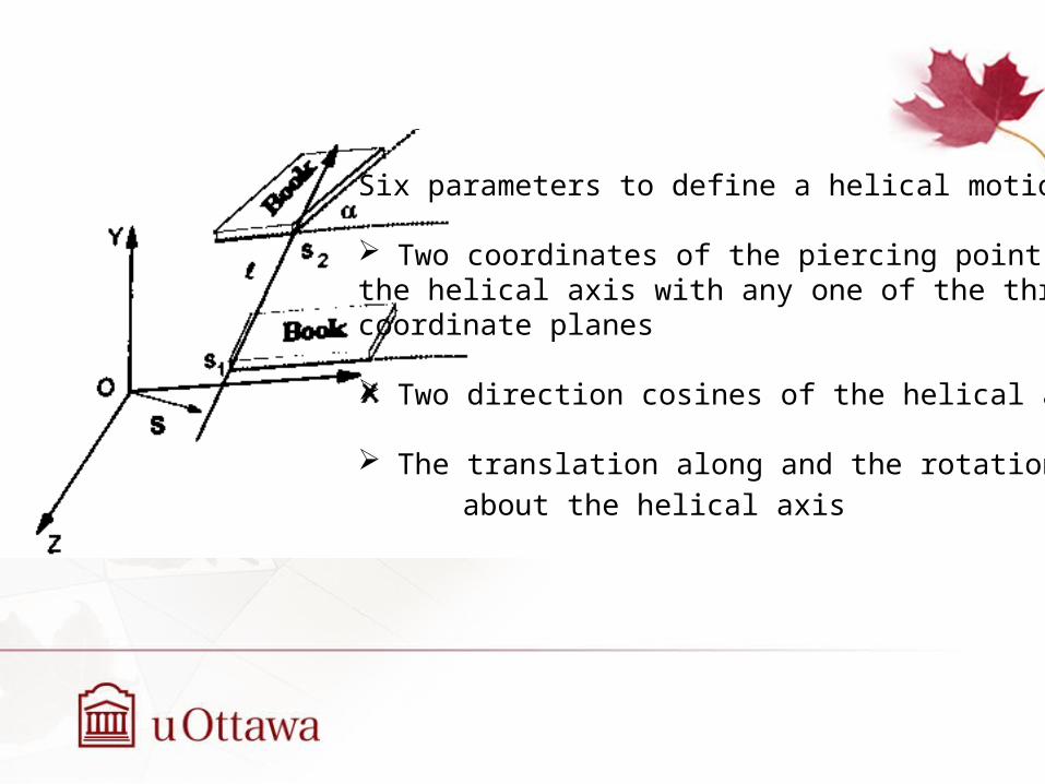
Six parameters to define a helical motion:
Two coordinates of the piercing point of the helical axis with any one of the three coordinate planes
Two direction cosines of the helical axis
The translation along and the rotation
about the helical axis

When using helical method
Large displacement of the glenohumeral joint Arm translation-arm rotation Euler angles are not specific

Thank You