joint researc h centre - scoteid€¦ · joint researc h centre ... iso has reserved a range of...
TRANSCRIPT

EC JRC IPSC Part 2-1/27
JointResearchCentre
EUROPEAN COMMISSION Institute for the Protection and the Security of the Citizen Traceability and Vulnerability Assessment Unit
Technical Guidelines For
Council Regulation No. 21/2004 of 17/12/2003
Part 2
Electronic Identifier and Reader Specifications Test procedures, acceptance criteria, and codification of
identifiers
Document reference G07-TRVA/ TG part 2 (2006)Version no. 1.0
Issue FinalDate of issue 10/07/2006

Technical Guidelines to Regulation 21/2004 Part 2 version 1.0
EC JRC IPSC Part 2-2/27
Technical Guidelines for Council Regulation No. 21/2004 of 17/12/2003
Table of Contents of Part 2 Chapter
Page
Introduction .............................................................................................................................. 4 1. Technical Characteristics of Electronic Identifiers and Readers .................................... 4
1.1 Principles of Operation of the Radio Frequency Identification (RFID) System.............. 4 1.2 ISO 11785 Full Duplex (FDX-B) Protocol ...................................................................... 5 1.3 ISO 11785 Half Duplex (HDX) Protocol......................................................................... 5 1.4. Compatibility of Readers and Electronic Identifier ........................................................ 6 1.5 Mandatory Requirements for Identifiers and Readers ..................................................... 6
2. Electronic Identification Code Structure........................................................................... 7 2.1 Re-tagging Counter (bits 2 to 4)....................................................................................... 8 2.2 User Information Field (bits 5 to 9) ................................................................................. 8 2.3. Country Code (bits 17 to 26)........................................................................................... 9 2.4 Animal Identification Code (bits 27 to 64) ...................................................................... 9
3. Equipment Type Approval Process .................................................................................. 10 3.1 Introduction .................................................................................................................... 10 3.2 Type Approval Procedure .............................................................................................. 10 3.3 Type Approval Maintenance.......................................................................................... 11 3.4 Specification for Electronic Identifiers and Readers ..................................................... 11
3.4.1 Component Identifier / Ordering Information.......................................................12 3.4.2 Intended Use..........................................................................................................12 3.4.3 Markings ...............................................................................................................12 3.4.4 Test Sample Identification ....................................................................................13 3.4.5 Primary Stage of Manufacture ..............................................................................13 3.4.6 Structurally Similar Components ..........................................................................13 3.4.7 Outline Drawing....................................................................................................13
3.5 Type Approval Test Schedule for Electronic Identifiers ............................................... 14 3.5.1 Laboratory Environmental Conditions..................................................................14 3.5.2 Sampling ...............................................................................................................14 3.5.3 Testing...................................................................................................................14 3.5.4 Visual Inspection and Dimensions........................................................................14 3.5.5 Functional Characteristics ..............................................................................14 3.5.6 Performance Verification ......................................................................................14 3.5.7 Mechanical and Thermal Robustness Tests ..........................................................15 3.5.8 Endurance Tests ....................................................................................................16 3.5.9 Acceptance Criteria ...............................................................................................16
3.6 Type Approval Test Schedule for Readers .................................................................... 16 3.6.1 Laboratory Environmental Conditions..................................................................16 3.6.2 Sampling ...............................................................................................................17 3.6.3 Testing...................................................................................................................17 3.6.4 Visual Inspection and Dimensions........................................................................17 3.6.5 Functional Characteristics .....................................................................................17 3.6.6 Performance Verification ......................................................................................17 3.6.7 Mechanical and Thermal Robustness Tests ..........................................................18 3.6.8 Endurance Tests ....................................................................................................18 3.6.9 Electromagnetic Immunity Profile ........................................................................19 3.6.10 Acceptance Criteria .............................................................................................20
4. Roles and Responsibilities of Test Laboratories ............................................................. 21

Technical Guidelines to Regulation 21/2004 Part 2 version 1.0
EC JRC IPSC Part 2-3/27
4.1 Requirements for Laboratories....................................................................................... 21 4.2 National Reference Laboratory (NRL) .......................................................................... 21 4.3 Technical Support from Commission Services.............................................................. 21
5. Application Date and Transitional Arrangements.......................................................... 22 Annex I – Considerations before Procurement ................................................................... 23 Annex II – Sample Certificate............................................................................................... 26 Annex III – Reference Documents........................................................................................ 27

Technical Guidelines to Regulation 21/2004 Part 2 version 1.0
EC JRC IPSC Part 2-4/27
Introduction
Part 2 of the technical guidelines describes the technical characteristics of electronic identifiers and readers, the test procedures and acceptance criteria for the equipment to be used in the Member States in conformance with Regulation 21/2004.
1. Technical Characteristics of Electronic Identifiers and Readers
1.1 Principles of Operation of the Radio Frequency Identification (RFID) System
The transponder consists of a plastic or glass package containing an integrated circuit fitted with an air or ferrite coil antenna (Figure 1). An identification number1 is encoded in the integrated circuit. A reading device emits an alternating magnetic field2 which transfers energy to the integrated circuit via its coil antenna, exploiting the physical phenomenon of inductive coupling. Once energised, the transponder sends its identification code back to the reader, and reverts to its passive state. The identification system is depicted in Figure 2 below.
Figure 1 a: RFID – Passive transponder in ear-tags Figure 1 b: RFID – Passive transponder in injectables or boluses
Figure 2: RFID – The complete electronic identification system for sheep and goats
1 According to ICAR: a code used to identify the animal individually, at national and, in combination with a country code,
on international level. It is a national responsibility to ensure the uniqueness of the national ID-code 2 According to ISO 11785: electromagnetic field transmitted by a transceiver to energize and/or activate a transponder
2) Antenna
4) Local IT application 5) Remote dBase
3) Reader unit 0999 123456789012
1) Transponders
Animal ID Code
Plastic cover
Integrated circuit and support
Ferrite coil antenna
Air coil antenna
Integrated circuit and support
Glass capsule
Technical Guidelines to Regulation 21/2004 Part 2 version 1.0
EC JRC IPSC Part 2-5/27
ISO has reserved a range of frequencies centred at 134.2 kHz for animal identification; and has defined two protocols for data transmission between transponders and readers in the ISO 11785 standard.
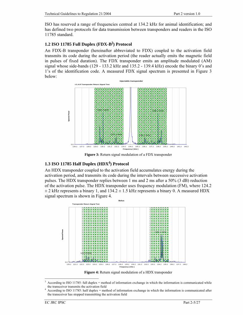
1.2 ISO 11785 Full Duplex (FDX-B3) Protocol An FDX-B transponder (hereinafter abbreviated to FDX) coupled to the activation field transmits its code during the activation period (the reader actually emits the magnetic field in pulses of fixed duration). The FDX transponder emits an amplitude modulated (AM) signal whose side-bands (129 - 133.2 kHz and 135.2 - 139.4 kHz) encode the binary 0’s and 1’s of the identification code. A measured FDX signal spectrum is presented in Figure 3 below:
Injectable transponder
138.2 kHz
136.2 kHz132.2 kHz
130.2 kHz
0.0126.2 127.2 128.2 129.2 130.2 131.2 132.2 133.2 134.2 135.2 136.2 137.2 138.2 139.2 140.2 141.2 142.2
Frequency [ kHz ]
Spec
tral
Pow
er
I.C.A.R Transponder Return Signal Test
Figure 3: Return signal modulation of a FDX transponder
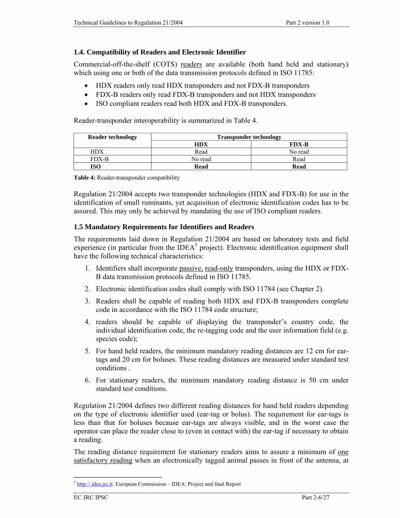
1.3 ISO 11785 Half Duplex (HDX4) Protocol An HDX transponder coupled to the activation field accumulates energy during the activation period, and transmits its code during the intervals between successive activation pulses. The HDX transponder replies between 1 ms and 2 ms after a 50% (3 dB) reduction of the activation pulse. The HDX transponder uses frequency modulation (FM), where 124.2 ± 2 kHz represents a binary 1, and 134.2 ± 1.5 kHz represents a binary 0. A measured HDX signal spectrum is shown in Figure 4.
Bolus
134.4 kHz
122.9 kHz
0.0120.2 121.2 122.2 123.2 124.2 125.2 126.2 127.2 128.2 129.2 130.2 131.2 132.2 133.2 134.2 135.2 136.2 137.2 138.2
Frequency [ kHz ]
Spec
tral
Pow
er
Transponder Return Signal Test
Figure 4: Return signal modulation of a HDX transponder
3 According to ISO 11785: full duplex = method of information exchange in which the information is communicated while
the transceiver transmits the activation field 4 According to ISO 11785: half duplex = method of information exchange in which the information is communicated after
the transceiver has stopped transmitting the activation field
Technical Guidelines to Regulation 21/2004 Part 2 version 1.0
EC JRC IPSC Part 2-6/27
1.4. Compatibility of Readers and Electronic Identifier
Commercial-off-the-shelf (COTS) readers are available (both hand held and stationary) which using one or both of the data transmission protocols defined in ISO 11785:
• HDX readers only read HDX transponders and not FDX-B transponders • FDX-B readers only read FDX-B transponders and not HDX transponders • ISO compliant readers read both HDX and FDX-B transponders.
Reader-transponder interoperability is summarized in Table 4.
Transponder technology Reader technology HDX FDX-B
HDX Read No read FDX-B No read Read ISO Read Read
Table 4: Reader-transponder compatibility Regulation 21/2004 accepts two transponder technologies (HDX and FDX-B) for use in the identification of small ruminants, yet acquisition of electronic identification codes has to be assured. This may only be achieved by mandating the use of ISO compliant readers.
1.5 Mandatory Requirements for Identifiers and Readers
The requirements laid down in Regulation 21/2004 are based on laboratory tests and field experience (in particular from the IDEA5 project). Electronic identification equipment shall have the following technical characteristics:
1. Identifiers shall incorporate passive, read-only transponders, using the HDX or FDX-B data transmission protocols defined in ISO 11785.
2. Electronic identification codes shall comply with ISO 11784 (see Chapter 2).
3. Readers shall be capable of reading both HDX and FDX-B transponders complete code in accordance with the ISO 11784 code structure;
4. readers should be capable of displaying the transponder’s country code, the individual identification code, the re-tagging code and the user information field (e.g. species code);
5. For hand held readers, the minimum mandatory reading distances are 12 cm for ear-tags and 20 cm for boluses. These reading distances are measured under standard test conditions .
6. For stationary readers, the minimum mandatory reading distance is 50 cm under standard test conditions.
Regulation 21/2004 defines two different reading distances for hand held readers depending on the type of electronic identifier used (ear-tag or bolus). The requirement for ear-tags is less than that for boluses because ear-tags are always visible, and in the worst case the operator can place the reader close to (even in contact with) the ear-tag if necessary to obtain a reading.
The reading distance requirement for stationary readers aims to assure a minimum of one satisfactory reading when an electronically tagged animal passes in front of the antenna, at
5 http://.idea.jrc.it: European Commission – IDEA: Project and final Report

Technical Guidelines to Regulation 21/2004 Part 2 version 1.0
EC JRC IPSC Part 2-7/27
walking speed in an appropriate race way (around 40 cm width according to the animal size), during dynamic reading in field conditions.
The quality of an RFID system may be quantified in terms of reading distances determined under standard test conditions (achieved in a controlled laboratory environment). However, it is important to note that reading distances may be considerably reduced in field (uncontrolled) conditions. Regulation 21/2004 sets the reading distance requirements appropriate for small ruminants. Specification of greater reading distances would help to protect investments by assuring that the same equipment will also be appropriate for electronic identification of larger animals such as cattle.
To facilitate and harmonise procurement operations for providers and users of devices and to help to protect investments, certain basic requirements for electronic identifiers and readers as shown in Annex I should be part of any call for tender.
2. Electronic Identification Code Structure
Uniqueness of electronic identification codes is of paramount importance for the successful implementation of an EU-wide system for electronic identification of livestock. This objective can be achieved through the use of a "country code" for each participating country, and the appointment of a national authority responsible for managing the identification codes inserted in electronic identifiers deployed on national territory.
Uniqueness of identification codes at EU level is a basic assumption for the interpretation and transparency of the information to be exchanged within and between countries when animals are transferred.
The objective of the codification system is to assure the traceability of basic data (e.g. information on date and place of origin) and historical data (e.g. movements throughout the EU) of the animal from birth to slaughter.
The link between the electronic identification code and the basic and historical details is established through the local and/or national animal registration system. In case of animals moved to another holding within the same country or to another Member State, the animal identification code and the movement document, should assure the link with the data-base in which the information relevant to the animal is available.
The Competent Authorities of the Member States shall be responsible for the assignment of unique animal identifier codes, and should define appropriate procedures for the delivery of electronic identifiers to users. According to ISO standards the Competent Authorities have to take all necessary measures to prevent any duplication of the identification codes of the animals. The most appropriate way would be to assign identification codes in progressive numbering irrespectively of the species they are assigned for.
To implement unique electronic identification of sheep and goats, the code structure of the transponder must comply with ISO 11784 and Regulation 21/2004: • 3 characters identify the Member State of the holding where the animal is first tagged.
For this purpose the ISO 3166 (3-digit numeric) country codes, shall be used; • 12 characters after the country code, used for the individual number of animal
identification. Following the interpretation that according to Regulation 21/2004 the conventional and electronic identification codes shall contain the same information, the individual conventional identification code can only consist of 12 digits with a maximum value of 274,877,906,944.
In ISO 11784, the transponder code is structured, as illustrated in Table 1 (ISO 11784:2004) below:

Technical Guidelines to Regulation 21/2004 Part 2 version 1.0
EC JRC IPSC Part 2-8/27
Bit (s)
no No of digits
No of combinations
Description
1 1 2 This bit indicates whether the transponder is used for animal identification or not. In all animal applications this bit shall be 1
2-4 1 8 Retagging counter (0 to 7) 5-9 2 32 User Information field
10-15 2 64 Empty – All zeros (reserved zone for future applications) 16 1 2 Bit indicating the presence or not of a data block (for the use in
animals this bit shall be 0 = no data block) 17-26 4 1,024 Mandatory ISO 3166 numeric 3-digit country code 27-64 12 274,877,906,944 National Identification Code (unique number in each country from 1
to 274,877,906,944)
Table 1: Structure of the identification code for electronic animal identification according to ISO 11784:2004 In practice, an animal identification would read as follows:
Type of identifier Animal identification code Interpretation of code Conventional ear-
tag 380 274000022501 380 = country code, 274000022501 = individual animal number
Electronic identifier
(electronic ear-tag or ruminal bolus)
1 0 04 00 0 380 274000022501
1 = animal identifier, 0 = retagging counter – no re-tagging, 04 = species code for sheep and goats, 00 = reserved zone, 0 = no data block, 380 = country code, 274000022501 = individual animal number
The Competent Authority in each Member State should define a policy for the use of the re-tagging counter and the user information field (e.g. species code). The application of ISO 11784 has to be made in the following manner:
2.1 Re-tagging Counter (bits 2 to 4)
These 3 bits provide information on the re-tagging of the animal: • At the first application of an electronic identifier to an animal, the number (re-
tagging code) has to be set to 0. • When an animal needs to be re-tagged (due to a lost or failed electronic device) this
number shall be set to 1 for the first re-tagging. As a total of 8 codes are possible (23), it will be possible to retag the same animal up to seven times. For more re-tagging, an authorisation of the Competent Authority must be necessary in order to re-tag the animal with a new identification number. In this case, the re-tagging counter will be returned to “0”
As regards the re-tagging requirements under Regulation 21/2004, reference is made to Part 1, chapter 2.3.3 of these guidelines.
2.2 User Information Field (bits 5 to 9)
ISO 11784 allows these 5 bits to be used for information defined by the user. According to ISO 11784, the Competent Authority in each country is responsible for the approval and assignment of the individual identification code to an animal and may decide also to include codification of animal species in the transponder. For a harmonised approach under Regulation 21/2004 when using the information field Member States shall utilize the codification of animal species by using the last two digits of the codification previously established by Council Regulation (EEC) No 2658/87, of 23 July 1987, for the implementation of tariff and statistical nomenclature for the Common Custom Tariff. The existing Combined nomenclature (CN) codes and the corresponding species codes for the transponder are listed in Table 2.

Technical Guidelines to Regulation 21/2004 Part 2 version 1.0
EC JRC IPSC Part 2-9/27
CN code
Transponder species code
Animal species
- 00 No species code defined 0101 01 Live horses, asses, mules and hinnies 0102 02 Live bovine animals 0103 03 Live swine 0104 04 Live Sheep and goats 0105 05 Live poultry, that is to say, fowls of the species Gallus domesticus, ducks,
geese, turkeys and guinea fowls 0106 06 Other live animals
Table 2: CN codification of species and equivalent codes for transponder’s specie codification
2.3. Country Code (bits 17 to 26)
These 10 bits specify the country code according to the ISO 3166 standard as illustrated in Table 3 for the EU Member States and candidate countries.
European Union Member Sates Candidate Countries
Country 2 Alfa-code 3 Numeric code Country 2 Alfa-code 3 Numeric code Austria AT 040 Bulgaria BG 100 Belgium BE 056 Croatia HR 191 Cyprus CY 196 Romania RO 642 Czech Republic CZ 203 Turkey TR 792 Denmark DK 208 Estonia EE 233 Finland FI 246 France FR 250 Germany DE 276 Greece EL 300 Hungary HU 348 Ireland IE 372 Italy IT 380 Latvia LV 428 Lithuania LT 440 Luxembourg LU 442 Malta MT 470 Poland PL 616 Portugal PT 620 Slovakia SK 703 Slovenia SI 705 Spain ES 724 Sweden SE 752 The Netherlands NL 528 United Kingdom GB 826
Table 3: ISO 3166 country codification
A total of 1,024 country codes are possible (210) but no ICAR manufacturer’s code is allowed.
2.4 Animal Identification Code (bits 27 to 64)
These 38 bits concern the unique identification number for each animal in each country. It can not be greater than 274.877.906.944 (238) individual codes in each country. As conventional and electronic identification codes shall be the same, this has to be taken into account when the individual identification codes contain preceding regional or holding codes.

Technical Guidelines to Regulation 21/2004 Part 2 version 1.0
EC JRC IPSC Part 2-10/27
3. Equipment Type Approval Process
3.1 Introduction
The equipment type approval process establishes a list of preferred or acceptable components (e.g. transponders, ear-tags, ruminal boluses, readers), from which items may be selected at the design, procurement and operational stages of the electronic identification system.
The type approval process is designed to provide end-users with assurances regarding the performance, interoperability, and reliability of approved components for animal identification in accordance with Regulation 21/2004.
The type approval process is implemented by the National Reference Laboratories (NRLs) (or national Competent Authorities) acting in concert with the Community Reference Laboratory (CRL). Reference is made to Chapter 4 of this document.
The type approval process rests on a series of interrelated documents (specifications), which are outlined in the following sections. The purpose of the specifications is:
1. to facilitate technical comparison between electronic identification equipment for the determination of their performance against the requirements specified in Regulation 21/2004;
2. to assist in negotiations between component manufacturers (e.g. suppliers of air- or ferrite-coil transponders, suppliers of ceramics), equipment manufacturers (e.g. suppliers of electronic ear-tags or ruminal boluses), and equipment users;
3. to permit the assessment of the quality (and hence, albeit indirectly, the reliability) of the component.
To meet these ends, the following information must be documented: 1. a description of each component, including: electrical, mechanical and
environmental ratings and characteristics; and the definition of the primary stage of manufacture of the component;
2. the procedures to be followed to ensure conformance with the requirements of Regulation 21/2004.
The primary stage of manufacture is that stage of the manufacturing process from which the manufacturer of a component shall demonstrate control over all aspects of the processes that affect the quality of the finished component. A manufacturer does not necessarily have direct control of all aspects of any preceding processes, but is responsible for accepting the quality achieved by them.
For the purposes of type approval, components are divided into families based principally on their function (e.g. transponders, ear-tags, boluses, hand-held readers, static readers etc.). As needs require, sub-families may be defined on the basis of function or technology or both.
As information required to specify a component (e.g. values for preferred dimensions, test severities, test requirements etc.) is common to more than one family or sub-family; a hierarchical specification structure will avoid unnecessary repetition and achieve uniformity of presentation.
3.2 Type Approval Procedure
The type approval procedure consists of the following three steps: 1. A component manufacturer seeking type approval submits a specification of the
component to a NRL of choice.

Technical Guidelines to Regulation 21/2004 Part 2 version 1.0
EC JRC IPSC Part 2-11/27
2. The NRL defines the requirements for approval of the component, taking any related component approvals into account. The NRL ensures that any conformance, performance, and reliability tests are executed on samples of the component and documented in a test report provided to the component supplier.
3. Type approval is attested by a certificate of the NRL and published by the CRL in the list of approved components. Type approval certificates unambiguously identify the component and its supplier. The component name appearing on the certificate shall be identical to the product identifier or part number which a customer would use to order the component from its supplier. A sample certificate is provided in Annex II to this document. A certificate issued by the NRL of a Member State and published by the CRL shall be recognised in all Member States, ensuring that a device receives a Community wide certification when successfully tested in one authorised laboratory.
The component specifications are the basis for the type approval maintenance process, described below.
The scheme is intended to permit a manufacturer of, for example, ruminal boluses to mix and match approved transponders with approved ceramic packages, as needs require. The type approval authority may thus avoid unnecessary repetition of laboratory tests, while the assurances provided to end-users can be maintained.
Clearly, the definition of type approval requirements will be affected by increasing complexity of the component under consideration as well as technological change. For these reasons, periodic reviews of the procedure by the CRL and the NRLs (or national Competent Authorities) should be foreseen.
3.3 Type Approval Maintenance
A type approval is valid as long as the approved component remains in continuous production. The production of a component is said to be continuous when:
1. there has been no change in the design, material or production process of the components affecting the type approval;
2. there has been no change in the place of manufacture; 3. there has been no break in production exceeding a period defined for the relevant
component family (typically one month).
A supplier can demonstrate continuity of production from the records created by the operation of a quality assurance scheme such as ISO 9001:2000.
Any change with respect to the three conditions specified above shall be notified to the NRL which granted the approval of the device, which shall define the requirements for type approval (i.e. from Section 3.2. Clause 2, above). A copy of this notification should be sent by the NRL to the CRL.
Note that if components are structurally similar i.e. they are produced by the same manufacturer with essentially the same design, materials, processes, and methods; then the results of tests carried out on one component can be recognised as being valid for the others of the group.
A statement of structural similarity is part of the component specification submitted with the request for type approval (i.e. in Section 3.2.Clause 1, above).
3.4 Specification for Electronic Identifiers and Readers
This section specifies the list of recommended contents for the description of an item of electronic identification equipment (ear-tag, bolus, transponder, reader, etc.), submitted by a

Technical Guidelines to Regulation 21/2004 Part 2 version 1.0
EC JRC IPSC Part 2-12/27
manufacturer to the type approval authority. Guidance on the contents of each clause, and the intended use of the contents is provided in the following subsections.
Clause Title Access
1 Component Identifier / Ordering Information Public
2 Intended Use Public
3 Markings Public
4 Test Sample Identification Public
5 Primary Stage of Manufacture Confidential
6 Structurally Similar Components Confidential
7 Outline Drawing Confidential Table 5: Recommended List of Contents for Specification of Electronic Identification Equipment
3.4.1 Component Identifier / Ordering Information
This clause shall define the name of a component, or the naming scheme for a family of components, as would be used by a customer when ordering the component from its supplier.
The information in this clause is considered public, and will appear in the list of approved or preferred components (i.e. the type approval certificate).
3.4.2 Intended Use
This clause shall give a clear and concise description of the purpose of the component, including any limitations. In particular:
1. All specifications shall define the intended operating environment of the component in terms of: ambient temperature and relative humidity limits; and electrical supply voltage and frequency limits, if applicable.
2. Specifications for identifiers shall list the animal species for which the identifiers are designed.
3. Specifications for boluses shall declare the recommended minimum age / live weight of the animal at tagging.
4. Specifications for readers shall state whether the equipment is hand-held, portable, and/or intended for permanent installations.
The information in this clause is considered public, and may appear in the type approval certificate. Publication of this information is intended to prevent misuse of the component.
3.4.3 Markings
This clause shall give a clear and concise description of the manufacturer’s scheme for the product identification information shown on the component and / or its package. Letter or colour codes shall be described in full or by reference to specifications published by the manufacturer. In particular:
1. markings shall permit the identification of the place and date of manufacture. 2. markings shall permit the identification of the version of the reader firmware
installed by the manufacturer. 3. non-synchronising readers shall bear a warning discouraging their use in the vicinity
of static readers (as required by ISO 11785 Clause 6)

Technical Guidelines to Regulation 21/2004 Part 2 version 1.0
EC JRC IPSC Part 2-13/27
The information in this clause is considered public, and may appear in the type approval certificate.
3.4.4 Test Sample Identification
This clause shall declare the lot number or production batch from which the component samples selected for type approval testing were drawn. The information in this clause shall be sufficient to identify the date and place of manufacture, and the materials, methods and processes used to produce the test samples.
Where the test samples are prototypes, this fact shall be noted.
The information in this clause is considered public, and may appear in the type approval certificate.
3.4.5 Primary Stage of Manufacture
This clause shall give a clear description of the primary stage of manufacture of the component (see Section 3.1). This clause shall declare the sources of the principal incorporated components or subsystems considered to have the greatest influence on the quality of the component with respect to the requirements of Regulation 21/2004. In particular:
1. Specifications for identifiers shall declare the source and type of the RFID transponder.
2. Specifications for boluses shall declare the source and type of the capsule / package used to set the size and weight of the identifier.
3. Specifications for readers shall declare the source and type of the RF module used to generate the transponder activation field, and / or to receive the transponder return signal.
The information in this clause is considered confidential, and will only be used by the type approval authority for the purpose of defining requirements for type approval (Section 3.2 Clause 2).
3.4.6 Structurally Similar Components
This clause shall give a clear description of the extent of structural similarity between the members of a product family. An example of a structurally similar component family might be a range of electronic ear-tags, encapsulating the same type of RFID transponder in the same type of polymeric material but manufactured in different sizes; or marketed under different brand names.
The information in this clause is considered confidential, and will only be used by the type approval authority for the purpose of defining requirements for type approval (Section 3.2 Clause 2).
3.4.7 Outline Drawing
An outline drawing of the component with main dimensions, including an illustration of the general outer appearance of the component. For structurally similar components, one outline drawing should be provided for each component.
The information in this clause is considered confidential, and will only be used by the type approval authority for the purpose of defining requirements for type approval (Section 3.2 Clause 2).
Technical Guidelines to Regulation 21/2004 Part 2 version 1.0
EC JRC IPSC Part 2-14/27
3.5 Type Approval Test Schedule for Electronic Identifiers
3.5.1 Laboratory Environmental Conditions
All type approval tests and measurements are performed under the following laboratory conditions:
• Ambient temperature 15°C – 35°C • Relative humidity: 25% - 75% • Atmospheric pressure: 860 hPa – 1060 hPa
3.5.2 Sampling
Fifty identifiers for type approval testing shall be taken at random from a production lot. The identifiers shall have been produced using the materials and components listed in the manufacturer’s specification (see Section 4.2), and have been subjected to the manufacturer’s normal inspection, quality control and production acceptance procedures.
3.5.3 Testing
Five identifiers are set aside for use as references for comparisons with the remaining forty five identifiers subjected to the robustness and endurance tests.
After the robustness tests, 2 identifiers are subjected to the electrical endurance test, and the remaining forty three identifiers are subjected to the mechanical and thermal endurance tests.
3.5.4 Visual Inspection and Dimensions
The initial visual inspection of each identifier in the test sample shall: 1. Verify that visible markings correspond to the manufacturers’ specification (see
Section 3.4) and conform to Regulation 21/2004 requirements. 2. Visually inspect each identifier to confirm identifier integrity and the absence of
damage. 3. Verify that identifier dimensions correspond to the manufacturer’s outline drawing
(see Section 3.4.7).
Visual inspections shall be conducted under a level of illumination not less than 1000 lux.
3.5.5 Functional Characteristics
Functional characteristics of the identifiers have to be checked in order to:
1. Verify that each identifier meets ICAR Part I conformance test requirements (full test procedure);
2. Verify that the structure of the identification code complies with the requirements of ISO 11784 and Regulation 21/2004.
3.5.6 Performance Verification
The system performance requirement defined in Regulation 21/2004 is reproduced in Table 6. The reading distances achieved with each identifier in the test sample are determined under standard test conditions with the transponder in at least two different orientations (most- and least-favourable) with respect to the reader antenna. The average of the two distances measured shall be equal or greater than the mandatory values defined in Table 6.

Technical Guidelines to Regulation 21/2004 Part 2 version 1.0
EC JRC IPSC Part 2-15/27
Electronic identifier Reader type
Ear-tag Bolus Hand held ≥ 12 cm ≥ 20 cm Stationary ≥ 50 cm
Table 6: Mandatory reading distances required by Regulation 21/2004
Standard test conditions for reading distance measurements are defined as follows: • Laboratory environmental conditions of ambient temperature, relative humidity and
atmospheric pressure • Test enclosure shielding performance: -60dB from 10kHz – 100kHz; -100dB from
200kHz – 18GHz • Electrical supply for mains-powered equipment: as specified for supply source in
IEC 61000-3-2 Limits for harmonic current emissions (e.g. 230V ±2%; 50Hz ±0.5%; harmonic distortion <0.9% at 3rd order; <0.4% at 5th order etc.).
These tests may be performed with type approved readers (i.e. golden standards) until a reference reading device becomes available.
3.5.7 Mechanical and Thermal Robustness Tests
The capacity of an identifier type to withstand mechanical and thermal stresses is evaluated by the test sequence laid down in Table 7.
The change of temperature test subjects the identifiers to differential thermal expansion stresses and is indicative of the compatibility of the materials used in identifier construction. The shock test for ear-tags simulates an impact. The severities for the dry heat and cold tests are appropriate for storage in locations which may have openings directly to the open air i.e. partially weatherprotected as defined in IEC 60721-3-1 Classification of groups of environmental parameters and their severities – Section 1: Storage.
Identifier Type Standard Test Severity
All types IEC 60068-2-14 Test Na – Change of temperature; Ta -40°C, Tb +85°C; exposure time 1 hour; 10 cycles
Ear-tag only IEC 60068-2-27 Test Ea – Shock: 2 shocks, 100g / 3ms; half-sine pulse; applied along main axis (temperatures to be considered)
Bolus only IEC 60068-2-32 Test Ed – Free fall: From 1 metre height onto concrete surface; 3 attitudes, 2 drops in each attitude
All types IEC 60068-2-2 Test Bb – Dry Heat: +70°C +/- 2°C for 48 hours
All types IEC 60068-2-1 Test Ab – Cold: -40°C +/- 2°C for 48 hours
Table 7: Mechanical and thermal robustness test sequence for electronic identifiers
At the end of each test, each identifer is subjected to a visual inspection, functional verification, and a performance check. Visual inspection after each test shall confirm the integrity of the identifier and the absence of plastic (i.e. permanent) deformation.
Functional verification after each test shall confirm the integrity of the electronic identification code.
Performance checks made after each test with a type approved reader(s) shall confirm the absence of a permanent reduction of reading distance at the end of the test sequence.

Technical Guidelines to Regulation 21/2004 Part 2 version 1.0
EC JRC IPSC Part 2-16/27
3.5.8 Endurance Tests
The capacity of an identifier type to operate after prolonged electrical, mechanical and thermal stresses is evaluated by the test sequence laid down in Table 8.
The swept-frequency vibration test subjects the identifiers to a wide spectrum of vibration frequencies which may be encountered at various stages in the identifier’s life-cycle (e.g. transport). Ear-tag functionality is verified at extreme operating temperatures. Long-term exposure to damp heat simulates the effects of ageing. .
Identifier Type Standard Test Severity
All types IEC 60068-2-6 Test Fc– Vibration (sinusoidal); Frequency sweep 10 Hz – 2000Hz; 0.75mm displacement / 10 g peak accel., crossover at 60Hz; sweep rate 1 octave / min; 10 cycles
Ear-tags only IEC 60068-2-2 Test Bb – Dry Heat: +55°C +/- 2°C for 24 hours; functional verification (reading of identification codes)
Ear-tags only IEC 60068-2-1 Test Ab – Cold: -25°C +/- 2°C for 24 hours; functional verification (reading of identification codes)
All types IEC 60068-2-78 Test Cab – Damp heat: +40°C / 93% relative humidity; 21 days exposure; functional verification (reading of identification codes)
Table 8: Endurance test sequence for electronic identifiers
Two identifiers are subjected to an electrical endurance test consisting of continuous reading as required to attain one million readings of the identification code.
At the end of each test, each identifer is subjected to a visual inspection, functional verification, and a performance check.
Visual inspection after each test shall confirm the integrity of the identifier and the absence of plastic (i.e. permanent) deformation.
Functional verifications during and / or after each test shall confirm the integrity of the electronic identification code.
Performance checks made after each test with a type approved reader(s) shall confirm the absence of a permanent reduction of reading distance at the end of the test sequence.
3.5.9 Acceptance Criteria
Type approval shall be awarded to an identifier type only if every identifier in the sample fulfils all requirements of the following sections:
1. Section 3.5.4 Visual Inspection and Dimensions. 2. Section 3.5.5 Functional Characteristics. 3. Section 3.5.6 Performance Verification. 4. Section 3.5.7 Mechanical and Thermal Robustness Tests. 5. Section 3.5.8 Endurance Tests.
3.6 Type Approval Test Schedule for Readers
3.6.1 Laboratory Environmental Conditions
All type approval tests and measurements are performed under the following laboratory conditions:
• Ambient temperature 15°C – 35°C • Relative humidity: 25% - 75%

Technical Guidelines to Regulation 21/2004 Part 2 version 1.0
EC JRC IPSC Part 2-17/27
• Atmospheric pressure: 860 hPa – 1060 hPa
3.6.2 Sampling Two readers, complete with antennas, for type approval testing shall be taken at random from a production lot. The readers shall have been produced using the materials and components listed in the manufacturer’s specification (see Section 3.2), and have been subjected to the manufacturer’s normal inspection, quality control and production acceptance procedures. The readers shall comply with electromagnetic emission legislation in force, e.g. European Radio Communications Office recommendation ERC 70-03 Annex 9 relating to the use of short-range devices (SRD).
3.6.3 Testing
One reader is set aside for use as a reference device for comparison with the reader subjected to the robustness and endurance tests.
3.6.4 Visual Inspection and Dimensions
The initial visual inspection of each reader in the test sample shall: 1. Verify that visible markings correspond to the manufacturers’ specification (see
Section 3.4). 2. Visually inspect each reader to confirm reader integrity and the absence of damage. 3. Verify that reader dimensions correspond to the manufacturer’s outline drawing (see
Section 3.4.7).
Visual inspections shall be conducted under a level of illumination not less than 1000 lux.
3.6.5 Functional Characteristics
Functional characteristics of the readers have to be verified in order to confirm that each reader meets ICAR Part 2 (non synchronizing readers) or ICAR Part 3 (synchronizing readers) transceiver conformance test procedure.
3.6.6 Performance Verification
The system performance requirement defined in Regulation 21/2004 is reproduced in Table 9. The reading distances achieved by each reader in the test sample are determined under standard test conditions with the transponder in at least two different orientations (most- and least-favourable) with respect to the reader antenna.
The average of the two distances shall be equal or greater than the mandatory values defined in Table 9.
Electronic identifier Reader type
Ear-tag Bolus Hand held ≥ 12 cm ≥ 20 cm Stationary ≥ 50 cm
Table 9: Mandatory reading distances required by Regulation 21/2004
Standard test conditions for reading distance measurements are defined as follows: • Laboratory environmental conditions of ambient temperature, relative humidity and
atmospheric pressure • Test enclosure shielding performance: -60dB from 10kHz – 100kHz; -100dB from
200kHz – 18GHz

Technical Guidelines to Regulation 21/2004 Part 2 version 1.0
EC JRC IPSC Part 2-18/27
• Electrical supply for mains-powered equipment: as specified for supply source in IEC 61000-3-2 Limits for harmonic current emissions (e.g. 220V ±2%; 50Hz ±0.5%; harmonic distortion <0.9% at 3rd order; <0.4% at 5th order etc.).
These tests may be performed with type approved identifiers (i.e. golden standards) until a reference identifier device becomes available.
3.6.7 Mechanical and Thermal Robustness Tests
The capacity of a reader type to withstand mechanical and thermal stresses is evaluated by the test sequence laid down in Table 10.
The free-fall tests simulate the effects of accidental dropping of the reader during normal use. The severities for the dry heat and cold tests are appropriate for storage in locations which may have openings directly to the open air i.e. partially weatherprotected as defined in IEC 60721-3-1 Classification of groups of environmental parameters and their severities – Section 1: Storage.
Reader Type Standard Test Severity
Hand-held IEC 60068-2-32 Test Ed – Free fall: From 1 metre height onto concrete surface; 3 attitudes, 2 drops in each attitude
Static (portable) IEC 60068-2-32 Test Ed – Free fall: From 50 centimetres height onto concrete surface; 3 attitudes, 2 drops in each attitude
Static (all types) IEC 60068-2-32 Test Ed – Free fall: Packed in its transport / carrying case; from 1 metre height onto concrete surface; 3 attitudes, 2 drops in each attitude
All types IEC 60068-2-2 Test Bb – Dry Heat: +70°C +/- 2°C for 48 hours
All types IEC 60068-2-1 Test Ab – Cold: -40°C +/- 2°C for 48 hours
Table 10: Mechanical and thermal robustness test sequence for readers
At the end of each test, the reader is subjected to a visual inspection, functional verification, and a performance check.
Visual inspection after each test shall confirm the integrity of the reader.
Functional verification after each test shall confirm the capability of the reader to correctly acquire both ISO 11785 FDX-B and HDX transponder identification codes.
Performance checks made after each test with a type approved identifier(s) shall confirm the absence of a permanent reduction of reading distance at the end of the test sequence.
3.6.8 Endurance Tests
The capacity of a reader type to operate during and/or after prolonged electrical, mechanical and thermal stresses is evaluated by the test sequence laid down in Table 11.
The swept-frequency vibration tests subject the readers to a wide spectrum of vibration frequencies which may be encountered at various stages in the reader’s life-cycle (e.g. transport). Reader functionality is verified at extreme operating temperatures. Long-term exposure to damp heat simulates the effects of ageing.

Technical Guidelines to Regulation 21/2004 Part 2 version 1.0
EC JRC IPSC Part 2-19/27
Reader Type Standard Test Severity
Hand-held and static (portable)
IEC 60068-2-6 Test Fc– Vibration (sinusoidal); Frequency sweep 10 Hz – 2000Hz; 0.75mm displacement / 10 g peak accel., crossover at 60Hz; sweep rate 1 octave / min; 10 cycles
Static IEC 60068-2-6 Test Fc– Vibration (sinusoidal); Frequency sweep 10 Hz – 2000Hz; 0.75mm displacement / 10 g peak accel., crossover at 60Hz; sweep rate 1 octave / min; 3 cycles
All types IEC 60068-2-2 Test Bb – Dry Heat: +55°C +/- 2°C for 24 hours; functional verification (reading of identification codes)
All types IEC 60068-2-1 Test Ab – Cold: -15°C +/- 2°C for 24 hours; functional verification (reading of identification codes)
All types IEC 60068-2-78 Test Cab – Damp heat: +40°C / 93% relative humidity; 10 days exposure; functional verification (reading of identification codes)
Table 11: Endurance test sequence for electronic identifiers
At the end of each test, the reader is subjected to a visual inspection, functional verification, and a performance check. Visual inspection after each test shall confirm the integrity of the reader. Functional verifications during and / or after each test shall confirm the capability to correctly acquire identification codes from FDX and HDX transponders. Performance checks made after each test with type approved FDX and HDX identifiers shall confirm the absence of a permanent reduction of reading distance at the end of the test sequence.
3.6.9 Electromagnetic Immunity Profile
The capacity of a reader type to operate in the presence of common electromagnetic disturbances, in particular disturbances with frequency components close to the 134.2 kHz operating frequency of animal identification systems, is evaluated by the test sequence laid down in Table 12.
The radiated radio-frequency (RF) immunity test profiles reader performance in the presence of RF radiation from intentional transmitters; however the standardised field modulation is not representative of common transmission formats (e.g. radio, television, cellular telephony, wireless data links).
The conducted perturbation tests simulate the effects of noise appearing on power lines, and are thus indicative of the quality of a reader’s power supply. A well-filtered power supply is important for the correct operation of all electronic equipment.
The electrostatic discharge test is particularly important for all hand-held electronic equipment.
Tests of reader immunity in the presence of wireless data link traffic are required, particularly as the adoption of wireless communications present opportunities for improving the environmental protection of readers, by reducing the number of openings required in the reader housing.

Technical Guidelines to Regulation 21/2004 Part 2 version 1.0
EC JRC IPSC Part 2-20/27
Reader Type Standard Test Severity
Static IEC 61000-4-3 Radiated RF field strengths 1 V/m, 3 V/m, 10 V/m; frequency ranges 80 MHz to 1 GHz, and 1.4 GHz to 2 GHz; carrier modulation 80% with 1 kHz sine wave
Static IEC 61000-4-4 Bursts applied to mains power supply lines in all coupling modes and polarities; severities 1 kV, 2 kV, 4 kV; test duration as required to determine reading efficiency for HDX and FDX-B transponders
Static IEC 61000-4-6 RF applied to mains power supply lines; RF frequency range 150kHz – 80MHz; severities 120 dbμV, 130 dbμV, 140 dbμV; test duration as required to determine reading efficiency for HDX and FDX-B transponders
All types IEC 61000-4-2 Electrostatic discharges – contact; severities 2 kV, 4 kV, 6 kV, and 8 kV; 10 discharges per point, during reading of both HDX and FDX-B transponders
Table 12: Endurance test sequence for electronic identifiers
The capacity of a reader type to correctly acquire FDX-B and HDX transponder identification codes in the presence of traffic typical of commonly used wireless data links (e.g. Bluetooth, 802.11 etc.) shall be verified.
The electromagnetic compatibility tests shall define the reader’s overall immunity profile, in terms of loss of functionality or performance degradation in the presence of the applied disturbance. Reader immunity profile is defined in terms of the following levels:
1. performance unaffected (best); 2. temporary loss of function or degradation of performance which ceases after the
disturbance ceases, and from which the equipment under test recovers its normal performance without operator intervention;
3. temporary loss of function or degradation of performance, the correction of which requires operator intervention;
4. permanent loss of function or degradation of performance which is not recoverable, owing to damage to hardware or software, or loss of data (worst).
The overall level achieved is determined by the worst result observed during the immunity profiling tests.
3.6.10 Acceptance Criteria
Type approval shall be awarded to a reader type only if each reader in the sample fulfils all requirements of:
1. Section 3.6.4 Visual Inspection and Dimensions; 2. Section 3.6.5 Functional Characteristics; 3. Section 3.6.6 Performance Verification;
and the reader subjected to tests:: 4. fulfils all requirements of Section 3.6.7 Mechanical and Thermal Robustness Tests. 5. fulfils all requirements of Section 3.6.8 Endurance Tests; 6. achieves an overall level of 1, 2, or 3 as defined in Section 3.6.9 Electromagnetic
Immunity Profile.
Technical Guidelines to Regulation 21/2004 Part 2 version 1.0
EC JRC IPSC Part 2-21/27
4. Roles and Responsibilities of Test Laboratories
4.1 Requirements for Laboratories
Member States should ensure that testing of equipment is carried out in laboratories authorized for such testing by the Competent Authorities. Test laboratories should have a demonstrable capability to perform the required tests. Test laboratories shall use the type approval test schedules listed in Sections 3.5 and 3.6 of this document, and record the test results for the purposes of type approval (e.g. test reports are sent to the NRL).
4.2 National Reference Laboratory (NRL)
The Competent Authorities shall designate a NRL for their Member State and ensure that it has the resources required to: - Coordinate standards and test methods in its Member State. - Establish an appropriate network of test laboratories within the Member State. - Ensure that the test laboratories perform tests in a comparable manner. - Act as the point of contact for other national reference laboratories and the CRL. - Act as the point of contact for equipment manufacturers and suppliers seeking type
approval. - Approve equipment on the basis of documented test results with notification to the CRL. - Operate the type approval maintenance procedure. - If considered necessary by the Competent Authorities, monitor the behavior of the
equipment in the field to establish whether the equipment meets expectations and to determine whether the type approval tests are appropriate.
A NRL may provide services to other Member States. Member States which decide not to set up a NRL may refer to a NRL in another Member State or to the CRL.
4.3 Technical Support from Commission Services
A Community Reference Laboratory (CRL) for animal electronic identification can be designated in accordance with Regulation (EC) No 882/20046. The CRL shall: - Publish and maintain the list of type approved equipment; - Review and update the type approval test procedures in concert with the NRLs, and with
international organizations such as ISO and ICAR; - Ensure that the NRLs perform tests in a comparable manner; - Provide technical support to the national Competent Authorities and the NRLs; - Provide technical support to the Commission and collect and collate data and
experiences on electronic animal identification within the Community; - Maintain a capability for performing routine tests and measurements.
Until a CRL is appointed, the Joint Research Centre of the Commission (JRC) shall carry out the functions and duties of a CRL.
6 Regulation (EC) No 882/2004 of the European Parliament and of the Council of 29 April 2004 on the official controls
performed to ensure the verification of compliance with feed and food law, animal health and animal welfare rules – OJ L 165, 30.04.2004, in the version of OJ L 191, 28.05.2004, p.1

Technical Guidelines to Regulation 21/2004 Part 2 version 1.0
EC JRC IPSC Part 2-22/27
5. Application Date and Transitional Arrangements
From 1.1.2007, the IDEA certification shall cease to be accepted, and only equipment approved according to the procedures laid down in this document should be procured for the purposes of Regulation 21/2004.
To ensure a smooth transition from the IDEA certification system to the Equipment Type Approval Process, the following measures shall be applied:
To ensure that a variety of equipment is type approved before electronic identification of small ruminants becomes compulsory in 1.1.2008, manufacturers may request (re-)testing of their products in accordance with the Equipment Type Approval Process defined in Part 2, Chapter 4 of the Technical Guidelines (this document) from 1.9.2006.
Until an adequate number of authorised laboratories and NRLs are set up in the Member States, the JRC will carry out type approval tests and issue equipment type approval certificates, allowing Member States the time required to build up an appropriate laboratory network.

Technical Guidelines to Regulation 21/2004 Part 2 version 1.0
EC JRC IPSC Part 2-23/27
Annex I – Considerations before Procurement
The administrative procedure to be followed for procurement and/or for a call for tender may vary in the different Member States, and therefore, this Chapter should only be seen as a aide-memoir to address certain important administrative and technical issues.
Before any procurement or call for tender is launched the following points should be taken into consideration: • What animals have to electronically identified (species, breeds, age/live weight at
tagging)? • What readings have to be performed and where (e.g. readings during tagging only,
connection of electronic identification with other parameters during reading, download of readings onto a database, dynamic reading with mobile equipment or stationary fixed reading)?
• Who should use the equipment (holder, market staff, transporters, veterinary services, slaughterhouse staff)?
• What specifications the equipment should meet and how these should be proven by the manufacturer/suppliers and how this will be verified (assessment procedure)?
In the procurement request or call for tender the requirements for the equipment should be as detailed as possible to help the manufacturer/supplier to offer the most suitable equipment for the purpose. At the moment a variety of equipment, having different specifications, is commercially available. Such specifications may also provide the legal basis for resolution of disputes between purchasers and suppliers:
a. Species, breed(s), age/live weight for which the equipment should be suitable;
b. Type and amount of equipment requested;
c. Delivery schedule (dates, delivery in a single lot or in several lots over a given period of time);
d. Proofs of conformity provided by the manufacturers/suppliers regarding specifications, quality and reliability of both products and manufacturer, e.g.:
• Type Approval Certificates for the equipments issued by a NRL or the CRL;
• Manufacturing quality assurance procedures (e.g. ISO 9000);
e. The procedure (if any) that will be implemented to assess conformity of the equipment with requirements, including possible tests, such as materials used, weight, size, shape, compliance of code structure, resonance frequency, reading distance;
f. Dispute resolution procedure, including purchasers and manufacturer’s/supplier’s liability.
In addition
For electronic identifiers (ruminal boluses, electronic ear-tags), the following requirements should be requested: a. The manufacturer has to be officially authorized for the production of electronic
identifiers by the Competent Authorities;

Technical Guidelines to Regulation 21/2004 Part 2 version 1.0
EC JRC IPSC Part 2-24/27
b. The bolus or ear-tag type shall be certified by a NRL or the CRL according to the Type Approval Procedures laid down in this document;
c. The bolus or ear-tag shall meet the predefined material, size, weight, and shape as specified in the procurement request;
d. The transponder code structure shall be in compliance with ISO 11784, Regulation 21/2004 and any applicable national rules for the re-tagging counter and the user information field (e.g. species code);
e. To ensure the minimum reading distance set up in the procurement request if above the minimum reading distance laid down in Regulation 21/2004 and certified in the Type Approval Certificate;
f. The transponder used in the ruminal boluses shall be “read-only”. OTP (One Time Programmable) transponders may be accepted if proof can be provided that with the writing of the transponders in a later stage any misuse or duplication is excluded, in particular that the process is under control and documented and the writing process ensures an irreversible modification of the transponder (fuse burning).
For bolus applicators, the following requirements should be requested: a. The size and length of the applicators shall be adequate to the bolus size and animal
species where the instruments will be used; b. The material shall be disinfectable and sufficiently robust; c. The applicator should not have sharp edges to avoid harm to the animals used for,
and the head should be replaceable.
for hand held readers, the following requirements should be requested: a. If to be used together with other portable or stationary readers, they shall
synchronise; b. The IP rating shall be more than IP 53; c. Possibility to work with internal or external batteries; d. The information on the display have to be easily read in any light conditions (<100
lux and > 100,000 lux); e. The reader shall be able to recover the whole code of the electronic identifier as
defined in ISO standard 11784; f. Beside the mandatory country code and individual identification code, it has to be
specified what other codes have to be displayed (re-tagging code, user information field);
g. The reader should be equipped with an acoustic confirmation tone when captured a code and a different acoustic warning tone if no reading has been achieved;
h. The reader should be equipped with an acoustic warning tone in case of double registration (only for readers with a memory);
i. The reader has to be equipped with a keyboard (if planned to be used to link the identification code with other parameters during the reading;
j. The reader has to be equipped with one or more communication interface(s) for data exchange (if possible specify, e.g. RS0232, USB, etc.) (only for readers with memory);
k. Additional features, such as charger, additional batteries for a predefined continuous functioning, cables, external antenna and cover.

Technical Guidelines to Regulation 21/2004 Part 2 version 1.0
EC JRC IPSC Part 2-25/27
for stationary readers, the following requirements shall be requested: a. If to be used together with other stationary or hand held readers, they shall
synchronise; b. The IP rating shall be more than IP 53; c. The equipment should be declared to be sufficiently robust and reliable to provide
the expected performance in hostile environment, such as slaughterhouse, milking parlour and –more in general- in any farming conditions where high level of electromagnetic interference may occur.
d. Possibility to work with internal or external batteries; e. The reader shall be able to recover the whole code of the electronic identifier as
defined in ISO standard 11784; f. The reader should be equipped with an acoustic or optical indicator of code reading,
the power line and possible malfunctioning (including interferences); g. The reader has to be equipped with one or more communication interface(s) for data
exchange (if possible specify, e.g. RS0232, USB, etc.); h. Concerning the antenna, it shall be manufactured using anti-shock materials and
connectors resistant to dust and humidity; i. Additional features, such as charger, additional batteries for a predefined continuous
functioning, cables, external antenna and cover.

Technical Guidelines to Regulation 21/2004 Part 2 version 1.0
EC JRC IPSC Part 2-26/27
Annex II – Sample Certificate
NRL Logo NRL NAME and ADDRESS
Date of Issue
TYPE APPROVAL CERTIFICATE No. XXX/year The following <component type> has met the requirements defined in the Technical Guidelines For Council Regulation No. 21/2004 of 17/12/2003 Part 2: Electronic Identifiers and Readers Specifications - Version X COMPONENT IDENTIFICATION Ordering information as defined in Section 4.2.1 SUPPLIER Contact information for supplier
Picture of the Device
TESTED ITEMS Test sample identification as defined in Section 4.2.4 The results of the tests applicable for type approval of this component are documented in Test Report XXX INTENDED USE Manufacturer’s definition of intended use of component as defined in Section 4.2.2 MARKINGS Manufacturer’s definition of marking scheme for component or component family, as defined in Section 4.2.3 ELECTROMAGNETIC COMPATIBILITY PROFILE The activation field strength of the reader, measured at 3m from the antenna, is XXX dbμA/m. Electromagnetic immunity test profile: overall level achieved: 1, 2, 3, or 4

Technical Guidelines to Regulation 21/2004 Part 2 version 1.0
EC JRC IPSC Part 2-27/27
Annex III – Reference Documents List and Details of Standards and Reference Documents used in the Guidelines Standard Title Date of Issue ISO 11784 Radio-frequency identification of animals – Code structure
Amendment 1 1996-08-15 2004-11-15
ISO 11785 Radio-frequency identification of animals – Technical concept 1996-10-15 ISO 3166 Codes for the representation of names of countries and their
subdivisions -- Part 1: Country codes 1997
ICAR – Part 1 Conformance Evaluation of RFID Devices, Part 1: ISO 11784/11785 conformance of Transponders including granting and use of a Manufacturer Code
June 2004
ICAR – Part 2 Conformance Evaluation of RFID Devices, Part 2: ISO 11784/11785 - conformance of transceivers - June 20004
ICAR – Part 3 Conformance Evaluation of RFID Devices, Part 3: Conformance test for non-synchronising transceivers for reading ISO 11784/11785 transponders
June 2004
ISO 17025 General requirements for the competence of testing and calibration laboratories 2005-05-15
IEC 60068-2-1 Environmental testing - Part 2: Tests A: Cold Amendment 1 Amendment 2
1990-04 1993-02 1994-05
IEC 60068-2-2 Environmental testing - Part 2: Tests B: Dry heat Amendment 1 Amendment 2
1974 1993-01 1994-05
IEC 60068-2-6 Environmental testing - Part 2: Test Fc: Vibration (sinusoidal) 1995-03 IEC 60068-2-14 Environmental testing - Part 2: Test Na: Change of temperature
Amendment 1 1984 1986-04
IEC 60068-2-27 Environmental testing. Part 2: Test Ea and guidance: Shock 1987/03 IEC 60068-2-32 Environmental testing. Part 2: Test Ed: Free fall
Amendment 2 1975/02 1990-10
IEC 60068-2-78 Environmental testing - Part 2-78: Test Cab: Damp heat, steady state 2001-08
IEC 60721-3-1 Classification of environmental conditions – Part 3: Classification of groups of environmental parameters and their severities – Section 1: Storage 1997-02
IEC 6100-3-2 Electromagnetic compatibility (EMC) – Part 3-2: Limits – Limits for harmonic current emissions 2001-01
IEC 61000-4-2 Electromagnetic compatibility (EMC) – Part 4-2: Testing and measurement techniques – Electrostatic immunity test 1999-05
IEC 61000-4-3 Electromagnetic compatibility (EMC) - Part 4-3: Testing and measurement techniques - Radiated, radio-frequency, electro-magnetic field immunity test Amendment 1 Amendment 2 2002-03
IEC 61000-4-4 Electromagnetic compatibility (EMC) - Part 4: Testing and measurement techniques - Section 4: Electrical fast transient/burst immunity test. Amendment 1 Amendment 2
1995-01 2000-11 2001-07
IEC 61000-4-6 Electromagnetic compatibility (EMC) - Part 4-6: Testing and measurement techniques - Immunity to conducted disturbances, induced by radio-frequency fields 2003-05