journal of advanced mechanical design, vol. 1, no. 1, 2007
TRANSCRIPT

Journal of Advanced Mechanical Design, Systems, and
Manufacturing
Vol. 1, No. 1, 2007
130
Modeling of a Hybrid System for a Lightweight Electric Vehicle with Passive-type Polymer
Electrolyte Fuel Cells and Electric Double-layer Capacitors
- Application of a Fuel Cell Equivalent Circuit Model -*
Hiroyuki IMANISHI**, Taichi YOSHII**, Takuji NAKAMURA**, Yogo TAKADA ** and Tomoyuki WAKISAKA**
**Department of Mechanical and Physical Engineering, Osaka City University 3-3-138 Sugimoto, Sumiyoshi-ku, Osaka 558-8585, Japan
E-mail: [email protected] Abstract
A simple series hybrid power system composed of passive-type polymer electrolyte fuel cells(PEFCs)and electric double-layer capacitors was adapted to a lightweight electric vehicle. In order to numerically simulate the behavior of the hybrid system, a fuel cell equivalent circuit model was applied and the model parameters were determined using an electrochemical theory and experimental results. Including this PEFC equivalent circuit model, a simulation model of the power train system (PEFCs, capacitors, motor, power controller, inertia, etc) of a lightweight electric vehicle was composed. It has been confirmed that this simulation model can represent reasonably well the dynamic behavior and energy transmission of the system in the experiment on a fixed apparatus constructed as a model of the vehicle.
Key words: Passive-type Polymer Electrolyte Fuel Cell, Electric Double-layer Capacitor, Hybrid System, Lightweight Electric Vehicle, Modeling, Electrochemical Theory
1. Introduction
In an aging society to come, the need of lightweight electric vehicles increases more and more. In the case of electric vehicles using batteries as a power source, there are problems such as short running distance per one charge and long time to charge them. As a power source of a lightweight electric vehicle, it is one of the best solutions at present to use polymer electrolyte fuel cells (PEFCs) fueled with hydrogen, because their emission is only water and the energy density and energy conversion efficiency of them are very high. However, when the vehicle needs high electric power or sudden change of motive power, there is a possibility that sufficient electric power cannot be supplied to the vehicle from the power source composed of only PEFCs. Consequently, the authors intend to use a hybrid power system which is composed of PEFCs and electric double-layer capacitors with high efficiency and high power density as an electric accumulator to cope with high power or sudden power change and to improve the energy efficiency of the whole system by regeneration of kinetic energy when a vehicle decelerates.
*Received 9 Jan., 2007 (No. T-04-1137) Japanese Original : Trans. Jpn. Soc. Mech.
Eng., Vol.71, No.708, C (2005), pp.2607-2613 (Received 19 Oct., 2004)
[DOI: 10.1299/jamdsm.1.130]
Journal of Advanced Mechanical Design,Systems, and Manufacturing
Vol. 1, No. 1, 2007
131
It is necessary to contrive the method of supplying electric power from PEFCs and capacitors to a motor, because their characteristics are very different. The authors have devised an original method “Time-Splitting Method (TSM)” with regard to supply of electric power to a motor(1). This TSM is applicable to both a series hybrid system and a parallel hybrid system. In a series hybrid system, electric power is supplied from PEFCs to capacitors and from capacitors to a motor alternately. On the contrary, in a parallel hybrid system, electric power is supplied from both of PEFCs and capacitors to a motor. In this study, the series hybrid system with passive-type PEFCs and electric double-layer capacitors for a lightweight vehicle is taken up as an object for modeling and simulation.
In general, it is not easy to select PEFCs and capacitors suitable for a lightweight electric vehicle in consideration of power and capacitance, respectively, and this selection needs a lot of trial and error experiments. Therefore, as an easier way, it is desirable to select PEFCs and capacitors by numerical simulation on the basis of a simulation model, which has to be composed for a hybrid system on a lightweight electric vehicle.
In this study, the simulation model of a passive-type PEFC is composed on the basis of a fuel cell equivalent circuit instead of a steady state current-voltage curve (the I-V curve) for dealing with the transient response of the PEFC. The model parameters are determined for high accuracy and general use by adopting an electrochemical theory and using the data obtained by an experiment to measure the transient characteristic of the PEFC. The simulation results of the series hybrid system obtained by using a simulation model including this PEFC model are verified by comparing them with experimental results on a stationary experimental apparatus for a lightweight electric vehicle.
Since the simulation model of a hybrid electric vehicle and its power control by TSM was already described in the authors’ published paper(2), they are described briefly in the next chapter.
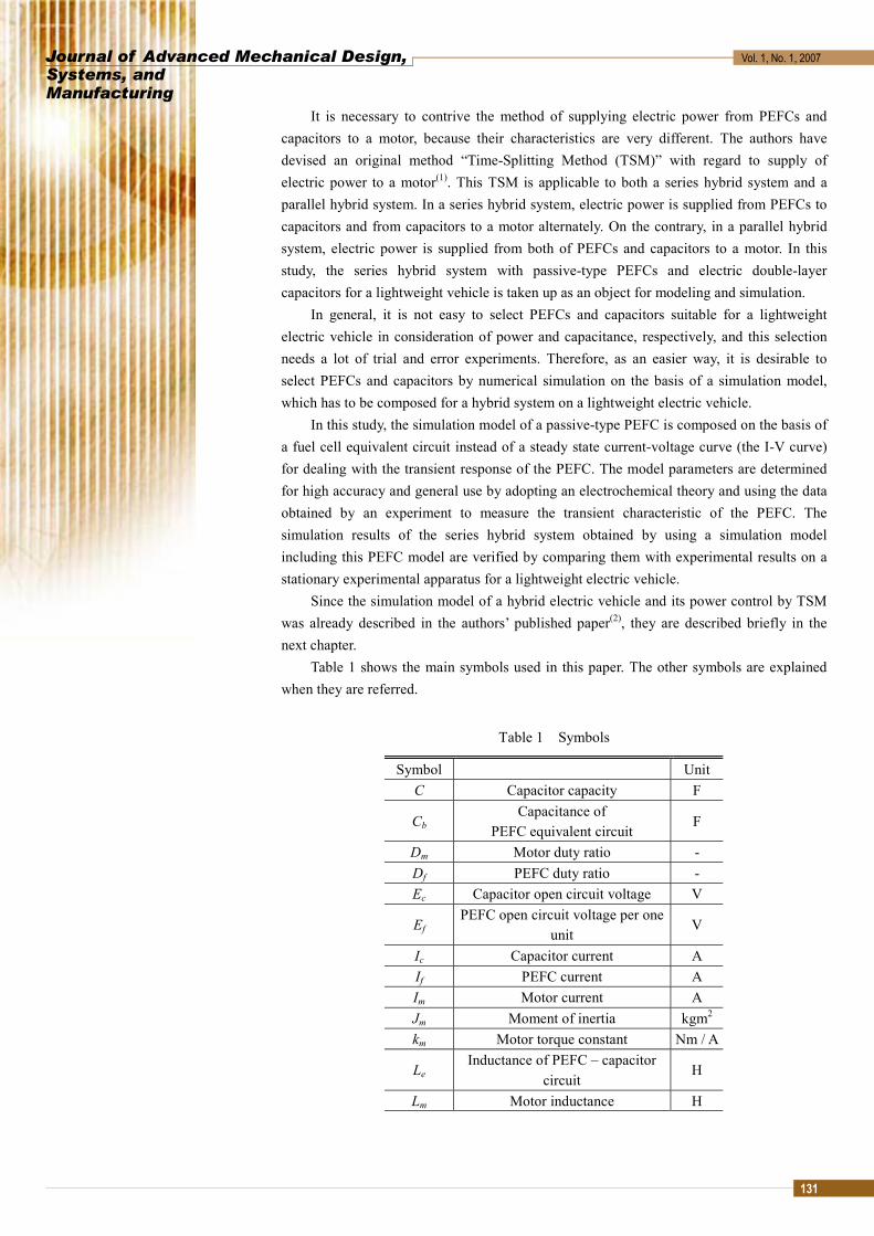
Table 1 shows the main symbols used in this paper. The other symbols are explained when they are referred.
Table 1 Symbols
Symbol Unit C Capacitor capacity F
Cb Capacitance of
PEFC equivalent circuit F
Dm Motor duty ratio - Df PEFC duty ratio - Ec Capacitor open circuit voltage V
Ef PEFC open circuit voltage per one
unit V
Ic Capacitor current A If PEFC current A Im Motor current A Jm Moment of inertia kgm2 km Motor torque constant Nm / A
Le Inductance of PEFC – capacitor
circuit H
Lm Motor inductance H

Journal of Advanced Mechanical Design,Systems, and Manufacturing
Vol. 1, No. 1, 2007
132
Pm Motor output W
Rb Reaction resistance of
PEFC equivalent circuit Ω
Rc Capacitor internal resistance Ω
Rf Electrolyte resistance of PEFC equivalent circuit
Ω
Rm Motor internal resistance Ω Tl Load torque Nm Tm Motor torque Nm tall Time per one control cycle s
tf(on) PEFC ON time per one cycle s tm(on) Motor ON time per one cycle s tm(off) Motor OFF time per one cycle s Vc Capacitor voltage V Vf PEFC voltage per one unit V Vm Motor voltage V v Vehicle speed km / h αf Charge duty ratio - ω Motor angular velocity rad / s
2. Simulation model of a hybrid electric vehicle
2.1 Experimental apparatus In this study, an electric wheelchair is assumed as an electric lightweight vehicle. The
experimental apparatus for this vehicle is mainly composed of electric power sources (two units of passive-type PEFCs and ten electric double-layer capacitors), a power control unit including a DC/AC inverter/converter, a motor and a flywheel as shown in Fig. 1.
The capacitors (maximum usage voltage: 23 V, electrostatic capacity: 2000 F per one capacitor) are connected in a series. As a motor to drive the vehicle, a three-phase AC permanent magnet synchronous motor (nominal voltage: 24 V, rated power: 250W) is used. The total mass of the targeted electric wheelchair is assumed to be 110 kg (vehicle: 30 kg, driver: 60 kg, maximum loading weight: 20 kg), and the flywheel in the experimental apparatus has inertia equivalent to the total mass of the vehicle.
Only the friction of a driving axle in the experimental apparatus is assumed as a load in this study, though the generator shown at the right end in Fig.1 can generate a running load such as a rolling resistance. This friction load is expressed as Eq.1 according to the experimental result. The specifications of the PEFC and power control unit with TSM are described later.
(1)
2.2 PEFC
The unit of PEFC used in this study is a commercial passive-type PEFC fueled with hydrogen (PFC1212, rated voltage: 12 V, rated power: 12 W) manufactured by Daido Metal Co., Ltd. and two units of the PEFCs are connected in series.
Since a passive-type PEFC does not employ any auxiliary devices such as air pumps, humidifiers, fuel and air flow controllers, and a temperature controller, the PEFC is favorable if the electric power required by the vehicle is relatively small and the space to
17.016.0 += vTl

Journal of Advanced Mechanical Design,Systems, and Manufacturing
Vol. 1, No. 1, 2007
133
install it is narrow. In this experiment, the gauge pressure of hydrogen in the fuel tank is 0.5 MPa and its pressure is reduced down to 0.17 MPa (gauge pressure) by a regulator for supplying to the PEFC units. Figure 2 shows the structure of a single cell of this PEFC unit. In the cell, electrochemical reaction occurs at room temperature between hydrogen coming through the central hole of the cell and oxygen coming from outside air, and the electrolyte membrane in the MEA (Membrane Electrode Assembly) is humidified with water generated by the reaction. In one unit of the PEFC, twenty cells are stacked in series as a total.
Fig. 1 Experimental apparatus
Fig. 2 Structure of a single cell of the passive-type PEFC unit 2.3 Power control by Time-Splitting Method
The Time-Splitting Method (TSM) is a method for easily controlling the power supply from an electric power source composed of passive-type PEFCs and capacitors to a motor, with a low-cost electric circuit(1) by making use of the merits that their electric power output response is good. In the case of the series hybrid system in this study, the motor is driven by the capacitors, and the PEFCs charge the capacitors as an on-site dynamo. Namely, one cycle of pulse-width modulation ( allt =84μm) is divided into one period (motor duty ratio mD ) for which the motor is driven by supplying the electric power from capacitors and the other period (PEFC duty ratio fD ) for which the capacitors are charged by the PEFCs.

Journal of Advanced Mechanical Design,Systems, and Manufacturing
Vol. 1, No. 1, 2007
134
Figure 3 shows the concept of power supply control by TSM among the PEFCs, capacitors and motor in the series hybrid system. The motor duty ratio fD is defined by Eq.2, which expresses the ratio of the motor-driving period to the PWM period allt . Six transistors FET1 (power MOSFET) in the inverter circuit shown in Fig.3 make switching operation according to the motor duty ratio mD . The PEFC duty ratio fD is defined by Eq.3, which expresses the coefficient fα times the ratio of the non-motor-driving period to the PWM period allt . The ratio fD is controlled by FET2 shown in Fig.3. The coefficient fα is defined by Eq.4, which is decided by both the electric power required to charge the capacitors and the ability of electric power supply from the PEFCs.
(2)
(3)
(4)
Fig. 3 Control of electric current between the PEFCs, capacitors and a motor by TSM
3. Modeling of a PEFC
This chapter describes the simulation model of the passive-type PEFC for applying it to the simulation model of the whole hybrid system which is described in the next chapter. In this study, a PEFC equivalent circuit model is employed for modeling the PEFC. The model parameters are determined on the basis of an electrochemical theory and by using the PEFC transient characteristic measured by experiment. 3.1 PEFC equivalent circuit
In this study, two units of passive-type PEFCs connected in series are used. One unit is composed of 20 cells stacked in series as mentioned before. As shown in Fig.4, the equivalent circuit of the one unit can be expressed by means of a direct-current power source with electromotive force fE , a capacitor with electrostatic capacity bC , a reactive resistance bR and an electrolyte resistance fR (membrane resistance plus various contact
)1()(mf
all
onff D
tt
D −== α
)10( ≤≤ fα)(
)(
offm
onff t
t=α
all
onmm t
tD )(=

Journal of Advanced Mechanical Design,Systems, and Manufacturing
Vol. 1, No. 1, 2007
135
resistances). The impedance fZ of the PEFC equivalent circuit at frequency f is expressed by Eq.5, where exR in the circuit is an external resistance which represents a load.
(5)
Fig. 4 Equivalent circuit of a PEFC unit 3.2 Determination of the circuit parameters on the basis of an electrochemical theory
The following electrochemical theory(3) is adopted to determine the parameters in the above-mentioned PEFC equivalent circuit and to give generality for the values of these parameters.
The PEFC terminal voltage fV is obtained from Eq.6. Here, the number of cells per one unit is n ( n =20 in this study). The open circuit voltage of one cell, fe (= nE f / ), is obtained from Eqs.(7) and (8) which are derived from the Nernst’s equation. Here,
2Oa ,2Ha , OHa
2are the activities of oxygen, hydrogen and water vapor, respectively.
Moreover, the activation over voltages of anode and cathode, aη and cη , are obtained from Eqs.(9) and (10), respectively.
(6)
(7)
(8)
(9)
(10)
A solid line in Fig.5(a) shows the fI - fV curve of the PEFC equivalent circuit calculated by substituting Eqs.(7)-(10) for Eq.(6) and using the physical constants shown in Table 2 and the constants in the PEFC electrochemical model shown in Table 3. Here, the values of fR , eai , eci , lai , lci and β in Table 3 were determined by trial and error so that the calculated values of fV might coincide with the measured values of fV (a dashed
2222
22
412
bb
fbbff RCf
RRRRZ
π+
++=
( ) ffcaff IRenV −−−= ηη
βln/ 0 zFRTenEe fff −==
−−=
la
f
ea
fa i
SIi
SIzF
RT 1lnln α
η
−−
−−=
lc
f
ec
fc i
SIi
SIzF
RT 1lnln)1( α
η
22
2
HO
OH
aaa
=β

Journal of Advanced Mechanical Design,Systems, and Manufacturing
Vol. 1, No. 1, 2007
136
line with □ marks) by experiment. In addition, the value of impedance at direct current ( f =0) can be expressed as
Eq.(11) which is derived from Eqs.(5) and (6). Consequently, the calculated fI - fZ curve for the PEFC equivalent circuit became a solid line in Fig.5(b). On the other hand, the measured fI - fZ curve by experiment under the same condition became a dashed line with □ marks in Fig.5(b).
(11)
It is found that the calculated results of fV and fZ based on the electrochemistry theory coincide well with the measured results by experiment except the region where the electric current is large. It seems that such disagreement of the calculated result with the measured result at the large electric current region is caused because the effects of diffusion polarization, flooding and cell temperature variation are not considered in the present PEFC model.
As a result, the reaction resistance at direct current, bR , can be expressed as Eq.(12) which is derived from Eq.(11).
(12)
Table 2 Physical constants
Symbol Constant Unit F Faraday constant 9.65×10⁴ C / mol R Gas constant 8.31 J / Kmol z Number of electrons 2 -
Table 3 Symbols and constants in the PEFC electrochemical model
Symbol Constant Unit ef 0 Standard open circuit voltage 1.23 V
iea Exchange current density
of anode 1.25×10⁻³ A / m2
iec Exchange current density
of cathode 2.0×10⁻³ A / m2
ila Limit current density
of anode 0.137×10⁴ A / m2
ilc Limit current density
of cathode 0.2×10⁴ A / m2
n Number of cells in a PEFC unit
20 -
Rf Electrolyte resistance 2.65 Ω S Effective area of reaction 13.0×10⁻⁴ m2 T Operation temperature 298 K α Transmission coefficient 0.5 - β Activity ratio 1.34×10¹³ -
ff
ca
f
ff
bfff
RI
nI
VE
RRZ
++
=−
=
+==
)()0(
ηη
f
cab I
nR
)( ηη +=

Journal of Advanced Mechanical Design,Systems, and Manufacturing
Vol. 1, No. 1, 2007
137
Fig. 5 Comparison of calculated and measured results on the characteristics of the PEFC unit
3.3 Determination of the circuit parameters on the basis of the transient characteristic of PEFC
The electrical time constant bτ in the bV part shown in Fig.4 is expressed as Eq.(13). Therefore, the capacitance element bC can be obtained from this equation by measuring the value of bτ . Here, fR is set at a constant value 2.65Ω obtained in the preceding section. Since bR is nearly constant unless the electric current is too small or too large, bR is assumed to be a constant value 0.5Ω. Figure 6 shows the temporal variation of the PEFC voltage
fV measured with an oscilloscope when the PEFC circuit changes instantaneously from an open circuit to a closed circuit (its external load is a resistor).
(13)
The measured value of electrical time constant bτ was 16.0 msec with the external
load resistance exR of 10Ω. By substituting bτ =16.0 msec, exR =10Ω, fR =2.65Ω, bR =0.5Ω for Eq.(13), the value of capacitance element bC became 33.3mF.
In the simulation model of the entire hybrid system, which will be described in the following chapter, it is decided to use the parameters obtained here for the PEFC part.
Fig. 6 Step response of PEFC voltage( exR =10 Ω)
4. Modeling of the entire hybrid system
4.1 Simulation model of the hybrid system for a lightweight electric vehicle The simulation model of the entire hybrid system including PEFCs, capacitors, a motor
bbexfb
exfb RC
RRRRR++
+=τ

Journal of Advanced Mechanical Design,Systems, and Manufacturing
Vol. 1, No. 1, 2007
138
and a load is composed for a lightweight electric vehicle. The circuit differential equation for the one PEFC unit is expressed as Eq.(14) on the
basis of the equivalent circuit and its parameters described in the foregoing chapter. The differential equations for the circuit between the PEFCs and the capacitors are expressed as Eqs.(15) and (16) in consideration of the inductance eL in the circuit and the internal resistance cR of the capacitors.
The differential equations for the circuit between the capacitors and the motor is expressed as Eqs.(17) and (18) in the case that the motor is driven with a 120-degree current-carry method. Here, )(θZ in Eq.(17) is a trigonometric function which changes according to the motor rotation angle θ . Moreover, the dynamic equation for the drive train system of a lightweight electric vehicle is expressed as Eq.(19).
The vehicle velocity v is expressed as ωkv = , where k is a coefficient representing the wheel diameter, the gear ratio, etc. The motor torque mT is expressed as
)(θZIkT mmm = (4), where mk is a torque constant. As the load torque lT , the linear function with respect to velocity v shown in Eq.(1) is used in this study.
(14)
(15)
(16)
(17)
(18)
(19)
The block diagram of the hybrid system constructed on the basis of Eqs.(14)-(19) is
shown in Fig.7. The input signal to the system is the motor duty mD for power control by TSM described in Section 2.3. Here, a switching parameter b whose value is determined from the value of mD is introduced to judge whether the capacitors are connected to a motor or the capacitors are connected to the PEFCs. Namely, the value of b is set at 1 within the period allmtD in one control cycle, while the value of b is set at 0 within the other period allm tD )1( − . In the block diagram, the parameter b is used as the coefficient derived from the equations concerning the electrifying state (Eq.(16), the first term of the right hand side in Eq.(17), and Eq.(18)). Therefore, in the numerical simulation of the hybrid system, the capacitor voltage cV is applied to the motor when b =1, but it is not applied to the motor when b =0.
b
bf
bb R
VIdt
dVC −=
( ){ }ffbfcfcf
e RIVERIEdt
dIL −−−+−= 2
)()( θωZkRIRIEdt
dIL mmmcmcm
m −−−=
CI
dtdE mc −=
)(),( vTITdtdJ lmmm −= θω
CI
dtdE fc =

Journal of Advanced Mechanical Design,Systems, and Manufacturing
Vol. 1, No. 1, 2007
139
Fig. 7 Block diagram of the hybrid system 4.2 Identification results
Numerical simulation was conducted on the basis of the block diagram described in the preceding section. The 7th-order implicit Runge-Kutta method based on the Kayo-Hisae formula with four implicit stages was employed for calculation. The simulation results and the experimental results which were conducted both on the same conditions are shown in Figs. 8 and 9. Figure 8 shows the results in the case that the initial vehicle velocity was 5 km/h and the signal of motor duty mD was raised like steps (the value of mD was initially set at 0.4 and changed to 0.6 after a lapse of 20 seconds from the start of measurement, and then changed to 0.8 after a lapse of 40 seconds from the start). Figure 9 shows the results in the case that the initial vehicle velocity was 8 km/h and the signal of motor duty mD was lowered like steps (the value of mD was initially set at 0.8 and changed to 0.6 after a lapse of 20 seconds from the start of measurement, and then changed to 0.4 after a lapse of 40 seconds from the start). In both experiments, the PEFC duty fD was set as mf DD −= 1 . It has been confirmed that the simulation model composed in this study can reproduce reasonably well the dynamic behavior of various variables on the system characteristics in the experiments under various conditions.
5. Conclusions
An equivalent circuit model for a unit of passive-type polymer electrolyte fuel cell (PEFC) has been composed on the basis of an electrochemical theory and with the transient characteristic of the PEFC measured by experiment. Then, a simulation model including the PEFC model has been composed for an entire hybrid system of a lightweight electric vehicle with passive-type PEFCs and electric double-layer capacitors. Numerical simulation of the hybrid system has been conducted using this simulation model. It has been confirmed that the simulation results on the transient response of the lightweight electric vehicle correspond to the experimental results reasonably well.
As a result, it is expected that the proposed simulation model is useful for determining the specifications of passive-type PEFCs and electric double-layer capacitors and for designing the control system of an electric lightweight vehicle.

Journal of Advanced Mechanical Design,Systems, and Manufacturing
Vol. 1, No. 1, 2007
140
Fig. 8 Identification result (Step-wise increase of mD )
Fig. 9 Identification result (Step-wise decrease of mD )
References
(1) Imanishi, H., Nakamura, T., Takada, Y. and Wakisaka, T., Fundamental Study on a Hybrid Power System of Passive-type Polymer Electrolyte Fuel Cells and Capacitors, J. Asian Electric Vehicles, 1-2 (2003), 463-470.
(2) Kamiya, N. and Umeda, M. ; Development and Prospect of Micro Fuel Cells, (2003), p.211, CMC Publishing.
(3) Masuko, N. and Takahashi, M.; Electrochemistry, (1996),pp.21-70, Agne Gijutsu Center. (4) Kenjo, T. and Nagamori, S. ; Brushless Motors, (2002), pp.134-137, Sougou Denshi
Publishing.