journal of science comparative analysis of optical
TRANSCRIPT

*Corresponding author, e-mail: [email protected]
Research Article GU J Sci 34(4): 1016-1033 (2021) DOI: 10.35378/gujs.774296
Gazi University
Journal of Science
http://dergipark.gov.tr/gujs
Comparative Analysis of Optical Multicarrier Modulations: An Insight into
Machine Learning-based Multicarrier Modulation
Augustus E. IBHAZE1,* , Frederick O. EDEKO2 , Patience E. ORUKPE2
1University of Lagos, Department of Electrical and Electronics Engineering, Akoka, Lagos, Nigeria 2University of Benin, Department of Electrical and Electronics Engineering, Benin City, Nigeria
Highlights
• This paper focuses on the comparative study of optical multicarrier modulation schemes.
• A machine learning-based multicarrier modulation is proposed for optical signal conditioning.
• An optimal system performance with reduced bit error rate response was achieved.
Article Info
Abstract
The performances of various optical multicarrier modulation schemes have been investigated in
this work by comparatively analyzing the bit error rate response relative to the signal to noise
ratio metric. The machine learning-based multicarrier modulation (MLMM) approach was
proposed and adopted as a method to improve the bit error rate response of the conventional
schemes. The results showed performance enhancement as the proposed machine learning
approach outperformed the conventional schemes. This proposition is therefore recommended for
adoption in the implementation of optical multicarrier modulation-based solutions depending on
the spectral and energy efficiency requirements of the intended application.
Received:27 July 2020
Accepted:27 Jan 2021
Keywords
Bit error rate
Machine learning
Multicarrier modulation
Signal to noise ratio
1. INTRODUCTION
Multicarrier technique has been well validated for application at radio frequency spectrum as a physical
layer standard for improved data rates up to megabits per second, although marked with some limitations
in its spectral/power efficiency, signal to noise ratio/bit error rate (SNR/BER) and limited bandwidth
requirement [1-3]. Following directly from this assertion is the larger bandwidth potential of the visible
light spectrum which makes it attractive for data rates up to gigabits per second and beyond [4]. The keen
interest in adapting radio frequency (RF)-based multicarrier scheme to visible light based multicarrier
scheme does not come by easily due to the inherent characteristics of the signal conditioning requirements
in the optical communication domain. For RF application, the signal is complex (with real and imaginary
signal components) and bipolar (positive and negative signal cycle) and must be transmitted via electrical
fields while being coherently detected. Conversely, for visible light application, the signal is real and
unipolar (positive) and can only be transmitted via optical intensity and received through direct detection
[5]. This has left the adoption of multicarrier modulation with orthogonal frequency division multiplexing
(OFDM) to ingenious investigations and implementation in the visible light communication plane. Since
the bandwidth requirement of the radio frequency spectrum places a natural limit on the achievable
throughput following directly from Shannon’s investigation on error free transmission [6], the enormously
large bandwidth of the visible light spectrum stands as an immediate and complementary solution to the
spectral crunch of radio frequency spectrum [7].
The design approach to improving throughput follows directly from the exploitation of the incoherent
nature of the optical signal in contrast with coherent radio frequency signal. In radio frequency domain,

1017 Augustus E. IBHAZE, Frederick O. EDEKO, Patience E. ORUKPE/ GU J Sci, 34(4): 1016-1033 (2021)
signal transmission is established through the electric field by varying the carrier’s amplitude, frequency
and phase. In a similar vein, for signal recovery, the carrier phase information of the transmitted signal will
be required by the receiver for detection and error free signal reconstruction. This coherence requirement
of the radio frequency system results in RF receiver design complexity since the phase difference has to be
analyzed and corrected. In this work, the carrier phase information will not be required by the receiver since
the transmitting source emits optical energy with changing phase. The receiver design complexity will be
greatly reduced since optical intensity can be directly detected using a photodetector. The implication of
this non-coherent signal reception is that the signal must be real and unipolar based on optical intensity,
unlike the radio frequency signal which is complex and bipolar based on the component property of signal
variation in the electric field. The conventional communication system comprises of three basic component
parts; the transmission, channel and reception module [8]. The design of these schemes depends largely on
user experience, expectations and local conditions. As users become more data hungry, the need to rollout
“more-broadband” technologies will become inevitable. And as such, existing techniques will have to
evolve into newer standards to cater for the increasing demand which comes with newer design challenges.
In terms of local conditions, the channel being line-of-sight (LOS) since signals will have to be directly
detected, channel parameters and propagation conditions also impose some constraints which necessitates
some level of ingenuity in signal processing and system design for error-free transmission.
Figure 1. Conventional Multicarrier Scheme for VLC [9]
The fundamental difference between the conventional scheme shown in Figure 1 and its radio frequency
counterpart is the process of generation of the real and unipolar signal required to drive the light emitting
diode (LED) transmitter and the direct detection module. The limitations imposed by the performance-
degrading effect of the high peak power associated with the OFDM scheme is also inherited by this model.
To improve upon the system performance, the communication link will require further processing scheme
to minimize the level of degradation while improving the system throughput.
2. MULTICARRIER MODELING FOR VISIBLE LIGHT COMMUNICATION (VLC)
Multicarrier techniques applies the strategy of splitting a high rate bit stream into a finite number of low
rate bit stream that can be transmitted over a finite number of subcarriers [10]. The bit stream is first
transmitted through a serial-to-parallel converter so that the encoded parallel bit stream can be modulated
on to the subcarriers using Inverse Fast Fourier Transform (IFFT). The inclusion of guard intervals and
cyclic prefix helps in the elimination of inter-symbol interference and inter-carrier interference respectively
[11]. At the receiving end, frequency offset estimation and symbol timing is done so that Fast Fourier
Transform (FFT) is applied on the symbols to detect the modulated subcarriers. A typical multicarrier
technique used in wireless communication is orthogonal frequency division multiplexing (OFDM). In VLC
variant of OFDM technique is being researched as possible technique for high throughput transmission.
Assuming that a single OFDM block is allocated a total number of N subcarriers, the serial bit-stream from
the transmitter is first converted to parallel bit-streams that can be modulated separately by the subcarriers,
mapped to the complex valued symbol (N⁄2)-1, in relation to the modulation constellation of the selected
Transmit
Bits
OFDM
Modulation DAC
DC Bias/
Clipping/
Flipping
LOS VLC
Channel
LED
PD ADC OFDM
Demodulation Equalization
Received
Bits

1018 Augustus E. IBHAZE, Frederick O. EDEKO, Patience E. ORUKPE/ GU J Sci, 34(4): 1016-1033 (2021)
scheme. The modulated OFDM block in relation to the subcarrier’s index is therefore given by:
𝑋 = [𝑋𝑙] ∀ 𝑙 = 0, 1, 2, . . . , 𝑁 − 1. (1)
where the subscript 𝑙 = 0, 1, 2, . . . , 𝑁 − 1 represent the subcarrier index in relation to the allocated
subcarriers.
To model a multicarrier signal conditioning scheme operating at a frequency 𝑓𝑜, it is to be noted that the
scheme denotes multiple carriers such that the cumulative effect is the sum total of the distinctive
subcarriers given as;
𝑥𝑡 = ∑ 𝑋𝑙𝑒(𝑗2𝜋𝑙𝑓𝑜𝑡)𝑁−1𝑙=0 ∀ 𝑙 = 0, 1, 2, . . . , 𝑁 − 1. (2)
where 𝑋𝑙 is the 𝑙𝑡ℎ subcarrier transmitted symbol, 𝑙𝑓𝑜𝑡 is the frequency component of the 𝑙𝑡ℎ subcarrier
and 𝑙 denotes the subcarrier index.
Since the given spectrum or bandwidth 𝐵 is bandlimited, it can be sampled at Nyquist rate:
2𝑓𝑚𝑎𝑥 = 2 .𝐵
2= 𝐵. (3)
The sampling duration or interval is given as the reciprocal of the sampling frequency 1
𝐵, such that the 𝑚𝑡ℎ
sampling instant becomes:
𝑚 .1
𝐵=
𝑚
𝐵. (4)
Since the total number of subcarriers for the multicarrier system is the same as 𝑁, then, the given bandwidth
will be shared by all 𝑁 subcarriers, so that the bandwidth of each subcarrier becomes:
𝑓𝑜 =𝐵
𝑁. (5)
Hence, Equation (2) on applying Equations (4) and (5) become:
𝑥𝑚 = ∑ 𝑋𝑘𝑒(𝑗2𝜋𝑘𝐵
𝑁 .
𝑚
𝐵)𝑁−1
𝑙=0 (6)
𝑥𝑚 = ∑ 𝑋𝑙𝑒(𝑗2𝜋𝑙𝑚
𝑁)𝑁−1
𝑙=0 ∀ 𝑙 = 0, 1, 2, . . . , 𝑁 − 1. (7)
Equation (7) is the multicarrier symbol. When impressed on the IFFT processor, the eventual output being
discrete time domain samples will yield the OFDM symbol of the 𝑙𝑡ℎ subcarrier expressed as:
𝑥𝑚 =1
√𝑁∑ 𝑋𝑙𝑒(𝑗
2𝜋𝑙𝑚
𝑁)𝑁−1
𝑙=0 ∀ 𝑚, 𝑙 = 0, 1, 2, . . . , 𝑁 − 1 (8)
where 𝑥𝑚, is the 𝑚𝑡ℎ time domain discrete sample and 1
√𝑁 is a scale factor [12]. But for visible light
applications with intensity modulation and direct detection, the OFDM signal must be represented by light
intensity. The implication of this property demands the modulating signal be real and unipolar (positive) as
opposed to the complex bipolar representation of the OFDM signal given by Equation (8). Since the total
number of subcarriers used is the same as 𝑁 2⁄ − 1, 𝑥𝑚 is derived as:
𝑥𝑚 =1
√𝑁∑ (𝑋𝑙𝑒
(𝑗2𝜋𝑙𝑚
𝑁)
+ 𝑋𝑁−𝑙𝑒(𝑗
2𝜋(𝑁−𝑙)𝑚
𝑁))𝑁 2⁄ −1
𝑙=0 . (9)

1019 Augustus E. IBHAZE, Frederick O. EDEKO, Patience E. ORUKPE/ GU J Sci, 34(4): 1016-1033 (2021)
In order to suppress the imaginary component of the IFFT processor output, Hermitian symmetry is
imposed. Consequently, to achieve real-valued time domain signal from the complex valued OFDM signal,
the allocated subcarriers are designed such that the subcarriers with subscript 𝑙 = 𝑁 2⁄ to 𝑁 − 1 (𝑋𝑁/2
to 𝑋𝑁−1) are constrained to satisfy Hermitian symmetry such that:
𝑋𝑙 = 𝑋𝑁−𝑙∗ ∀ 𝑙 = 𝑁 2⁄ , . . . , 𝑁 − 1 (10)
where the superscript “∗” connotes the complex conjugate of the specified subcarrier. Hence,
𝑥𝑚 =1
√𝑁∑ (𝑋𝑙𝑒
(𝑗2𝜋𝑙𝑚
𝑁)
+ 𝑋𝑙∗𝑒
(−𝑗2𝜋(𝑁−𝑙)𝑚
𝑁)) .
𝑁 2⁄ −1𝑙=0 (11)
The real component therefore derives directly from Equation (11) since the imaginary component is being
suppressed or forced to zero. Hence:
𝑥𝑚 =2
√𝑁∑ 𝑅𝑒 (𝑋𝑙𝑒
(𝑗2𝜋𝑙𝑚
𝑁))𝑁 2⁄ −1
𝑙=0 ∀ 𝑚, 𝑙 = 0, 1, 2, . . . , 𝑁 − 1. (12)
The basic property that describes the superiority of multicarrier scheme over single carrier technique is its
robustness in mitigating ISI effect over a dispersive channel by the simple integration of cyclic prefix. After
IFFT operation, cyclic prefix of a specified length 𝐿𝑐𝑦𝑝 is added in front of the OFDM block which must
exceed the maximum delay spread of the dispersive channel to effectively eliminate ISI effect. The time
domain discrete samples 𝑥𝑚 are then serialized by converting them to electrical signal 𝑥𝑡 using a digital-
to-analog converter (DAC). It is to be noted that the eventual output at this stage is still bipolar and
infeasible for intensity modulation. The next phase of adapting the bipolar OFDM signal is to achieve a
unipolar signal of the real valued version of the OFDM samples. In order to eliminate the undesirable effect
of direct current (dc) and complex valued harmonics, the modulated OFDM block is constructed such that
the subcarriers with subscript 𝑘 = 0 and 𝑘 = 𝑁 2⁄ are set to zero, that is:
𝑋0 = 𝑋𝑁/2 = 0. (13)
The remaining subcarriers 𝑋1 to 𝑋𝑁 2⁄ −1, are used to convey the information symbols.
2.1. Direct Current-biased Optical (DCO) OFDM
To derive the unipolar version of the bipolar OFDM signal 𝑥𝑡, a dc-bias ℬ𝑑𝑐 is added to the signal to force
the signal to be non-negative, derived in relation to the standard deviation of 𝑥𝑡 [13], such that:
ℬ𝑑𝑐 ∝ 𝜎𝑑 (14)
𝜎𝑑 = √𝐸(𝑥𝑡2) (15)
ℬ𝑑𝑐 = 𝜇𝜎𝑑 = 𝜇√𝐸(𝑥𝑡2) (16)
where 𝜇 is a constant of proportionality and 𝜎𝑑 is the standard deviation being the expectation 𝐸(. ) of the
OFDM signal. The level of bias ℬ𝑑𝑐 is estimated as:
𝛽 = 10𝑙𝑜𝑔(𝜇2 + 1) 𝑑𝐵. (17)
Since the spectral plane is shifted by dc-bias, the negative amplitudes of the biased signals are therefore
clipped to zero which further results in clipping distortion or noise 𝑛𝑐. The ensuing unipolar electrical DCO
signal used to drive the LED for intensity modulation becomes:
1020 Augustus E. IBHAZE, Frederick O. EDEKO, Patience E. ORUKPE/ GU J Sci, 34(4): 1016-1033 (2021)
𝑥𝐷𝐶𝑂 = 𝑥𝑡 + ℬ𝑑𝑐 + 𝑛𝑐 . (18)
In order to raise the negative peaks to zero, high dc biasing level will be required which makes this scheme
power inefficient although spectrally efficient since the entire subcarriers can be used as symbol carriers.
At 𝑁 ≥ 64, that is; for sufficiently large number of subcarriers, the signal 𝑥𝑡 approximately models a zero
mean Gaussian distribution based on the central limit theorem [14], having a variance of:
𝜎𝑑2 = 𝐸(𝑥𝑡
2) (19)
where, 𝜎𝑑 is the standard deviation of the signal 𝑥𝑡.
Since the power density function (pdf) models a Gaussian distribution given by [15]:
𝑓𝑋,𝐷𝐶𝑂(𝜗) =1
√2𝜋𝜎𝐷𝐶𝑂exp (−
(𝜗−ℬ𝑑𝑐)2
2𝜎𝐷𝐶𝑂2 ) 𝑢(𝜗) + 𝑄 (
ℬ𝑑𝑐
𝜎𝐷𝐶𝑂) 𝛿(𝜗) (20)
where 𝑢(𝜗) and 𝛿(𝜗) are unit step and Dirac delta functions respectively. The optical power of the DCO
scheme 𝑃𝑜,𝐷𝐶𝑂 follows directly from the pdf as:
𝑃𝑜,𝐷𝐶𝑂 = 𝐸(𝑥𝑡) = ∫ 𝜗𝑓𝑋,𝐷𝐶𝑂(𝜗)𝑑𝜗∞
0 (21)
𝑃𝑜,𝐷𝐶𝑂 = ∫ 𝜗 (1
√2𝜋𝜎𝐷𝐶𝑂exp (−
(𝜗−ℬ𝑑𝑐)2
2𝜎𝐷𝐶𝑂2 ) 𝑢(𝜗) + 𝑄 (
ℬ𝑑𝑐
𝜎𝐷𝐶𝑂) 𝛿(𝜗)) 𝑑𝜗.
∞
0 (22)
Given that Q-function Q(x) is given by
𝑄(𝑥) =1
√2𝜋∫ 𝑒𝑥𝑝 (−
𝑥2
2) 𝑑𝑥.
∞
𝑥 (23)
Then, the optical DCO scheme power will become:
𝑃𝑜,𝐷𝐶𝑂 =𝜎𝐷𝐶𝑂
2𝜋𝑒𝑥𝑝 (
−ℬ𝑑𝑐2
2𝜎𝐷𝐶𝑂2 ) + ℬ𝑑𝑐 (1 − 𝑄 (
ℬ𝑑𝑐
𝜎𝐷𝐶𝑂)). (24)
The electrical power 𝑃𝑒,𝐷𝐶𝑂 of the DCO scheme is given by [16]:
𝑃𝑒,𝐷𝐶𝑂 = 𝐸(𝑥𝑡2) = ∫ 𝜗2𝑓𝑋𝐷𝐶𝑂(𝜗)𝑑𝜗
∞
0 (25)
𝑃𝑒,𝐷𝐶𝑂 = ∫ 𝜗2 (1
√2𝜋𝜎𝐷𝐶𝑂exp (−
(𝜗−ℬ𝑑𝑐)2
2𝜎𝐷𝐶𝑂2 ) 𝑢(𝜗) + 𝑄 (
ℬ𝑑𝑐
𝜎𝐷𝐶𝑂) 𝛿(𝜗)) 𝑑𝜗.
∞
0 (26)
𝑃𝑒,𝐷𝐶𝑂 =𝜎𝐷𝐶𝑂ℬ𝑑𝑐
√2𝜋𝑒𝑥𝑝 (
−ℬ𝑑𝑐2
2𝜎𝐷𝐶𝑂2 ) + (ℬ𝑑𝑐
2 + 𝜎𝐷𝐶𝑂2 ) (1 − 𝑄 (
ℬ𝑑𝑐
𝜎𝐷𝐶𝑂)). (27)
At the receiving end, the photo-detector converts the received optical signal into electrical signal 𝑦𝑡 given
as:
𝑦𝑡 = ℎ𝑡 ∗ 𝑥𝐷𝐶𝑂 + 𝑛𝑤 . (28)
where ℎ𝑡 is the channel impulse response, ∗ denotes convolution and 𝑛𝑤 models the additive white Gaussian
noise with zero mean. The received signal 𝑦𝑡 is then fed into the analog-to-digital converter (ADC) to obtain
the discrete equivalent of the signal 𝑦𝑚 which is then de-cyclic prefixed and parallelized. That is:
𝑦𝑚; ∀ 𝑚 = 0, 1, 2, 3, . . . , 𝑁 − 1. (29)
1021 Augustus E. IBHAZE, Frederick O. EDEKO, Patience E. ORUKPE/ GU J Sci, 34(4): 1016-1033 (2021)
An N-point FFT is used to transform the time domain samples into frequency domain samples to enable
the recovery of the transmitted symbols. That is:
𝑌𝑙; ∀ 𝑙 = 0, 1, 2, 3, . . . , 𝑁 − 1. (30)
Since the subcarriers indicated by 𝑙 = 0, 1, 2, 3, . . . , 𝑁 − 1 are narrowband channels, they experience flat
fading such that single tap equalization technique becomes sufficient for estimation. Since subcarriers 𝑙 =0, 1, 2, 3, . . . , 𝑁 2⁄ − 1 are used for information symbol transmission, the equalizer divides each subcarrier
received symbol by its associated channel state information (CSI) for signal recovery. In a similar vein, the
adoption of machine learning for channel estimation as proposed in this work can greatly improve the BER
response and ultimately the optimal state of the recovered signal by training the distorted received signal
using ANN. The dataset training will help in the correlation of the distorted output and the transmitted
signal in relation to the predefined BER threshold to minimize the bit error rate.
The signal to noise ratio for the DCO scheme in relation to the optical 𝑆𝑁𝑅𝑜and electrical power 𝑆𝑁𝑅𝑒 are
given respectively by:
𝑆𝑁𝑅𝑜,𝐷𝐶𝑂 =𝐸(𝑥𝑡)
𝑏𝐷𝐶𝑂𝑁𝑜 (31)
and
𝑆𝑁𝑅𝑒,𝐷𝐶𝑂 =𝐸(𝑥𝑡
2)
𝑏𝐷𝐶𝑂𝑁𝑜 (32)
where 𝐸(𝑥𝑡) is the optical power, 𝐸(𝑥𝑡2) is the electrical power, 𝑏𝐷𝐶𝑂 is the throughput of the DCO scheme
and 𝑁𝑜 is the noise power. The bit error rate can therefore be estimated in relation to the signal to noise
ratio for the DCO scheme.
By way of extension, the average bit error rate, 𝐵𝐸𝑅𝑎𝑣𝑒 is defined as the ratio of the transmitted bit in error
to the total bits transmitted [17]. Such that:
𝐵𝐸𝑅𝑎𝑣𝑒 =∑ 𝑏𝑙𝐵𝐸𝑅𝑙
𝑁 2⁄ −1𝑙=1
∑ 𝑏𝑙𝑁 2⁄ −1𝑙=1
(33)
where 𝑏𝑙 is the transmitted bits per subcarrier, 𝐵𝐸𝑅𝑙, is the bit error rate per subcarrier and 𝑙 is the subcarrier
index.
Hence, in terms of DCO scheme, average BER becomes:
𝐵𝐸𝑅𝑎𝑣𝑒 =∑ 𝑏𝑙,𝐷𝐶𝑂𝐵𝐸𝑅𝑙
𝑁 2⁄ −1𝑙=1
∑ 𝑏𝑙,𝐷𝐶𝑂𝑁 2⁄ −1𝑙=1
. (34)
Hence, from Equation (34), the total DCO scheme transmits bit is given by:
𝑏𝐷𝐶𝑂 = ∑ 𝑏𝑙,𝐷𝐶𝑂𝑁 2⁄ −1𝑙=1 =
∑ 𝑏𝑙,𝐷𝐶𝑂𝐵𝐸𝑅𝑙𝑁 2⁄ −1𝑙=1
𝐵𝐸𝑅𝑎𝑣𝑒. (35)
By combining Equations (31), (32) and (35), the relationship between the SNR and BER is derived as:
𝑆𝑁𝑅𝑜,𝐷𝐶𝑂 = 𝐸(𝑥𝑡)
∑ 𝑏𝑙,𝐷𝐶𝑂𝐵𝐸𝑅𝑙𝑁 2⁄ −1𝑙=1
𝐵𝐸𝑅𝑎𝑣𝑒𝑁𝑜
(36)
𝑆𝑁𝑅𝑜,𝐷𝐶𝑂 =𝐵𝐸𝑅𝑎𝑣𝑒 . 𝐸(𝑥𝑡)
𝑁𝑜 ∑ 𝑏𝑙,𝐷𝐶𝑂𝐵𝐸𝑅𝑙𝑁 2⁄ −1𝑙=1
(37)

1022 Augustus E. IBHAZE, Frederick O. EDEKO, Patience E. ORUKPE/ GU J Sci, 34(4): 1016-1033 (2021)
𝑆𝑁𝑅𝑒,𝐷𝐶𝑂 =𝐸(𝑥𝑡
2)
∑ 𝑏𝑙,𝐷𝐶𝑂𝐵𝐸𝑅𝑙𝑁 2⁄ −1𝑙=1
𝐵𝐸𝑅𝑎𝑣𝑒𝑁𝑜
(38)
𝑆𝑁𝑅𝑒,𝐷𝐶𝑂 =𝐵𝐸𝑅𝑎𝑣𝑒 . 𝐸(𝑥𝑡
2)
𝑁𝑜 ∑ 𝑏𝑙,𝐷𝐶𝑂𝐵𝐸𝑅𝑙𝑁 2⁄ −1𝑙=1
. (39)
2.2. Asymmetrically Clipped Optical (ACO) OFDM
To improve on power efficiency, ACO-OFDM was modeled as a modification of the optical multicarrier
signal conditioning scheme. This model was able to achieve improved power efficiency by exploiting the
odd subcarriers while sacrificing the even subcarriers to cater for clipping distortion as the means to
achieving the unipolar signal. Since dc-bias is not required, there is a considerable tradeoff between power
and spectral efficiency as the spectral efficiency is considerably reduced due to the clipping of even
subcarriers. Hence only half of the total subcarriers required for symbol transmission are used. That is, one-
half of 𝑁 2⁄ being 𝑁 4⁄ subcarriers can be used for symbol transmission for an OFDM block of 𝑁
subcarrier. Since only odd subcarriers are used, 𝑋𝑙 of Equation (8) will become:
𝑋𝑙 = 𝑋2𝑛+1 ∀ 𝑛 = 0, 1, 2, 3, . . . , 𝑁 2⁄ − 1 (40)
so that the frequency domain signal becomes:
𝑋 = [0, 𝑋1, 0, 𝑋3, 0, 𝑋5, . . . , 𝑋𝑁 2⁄ −1, 0, 𝑋𝑁 2−1⁄∗ , . . . , 𝑋5
∗, 0, 𝑋3∗, 0, 𝑋1
∗]. (41)
Hence for ACO-OFDM scheme in terms of 𝑁 2⁄ − 1 subcarriers used for symbol transmission, Equation
(8) becomes:
𝑥𝑚 =1
√𝑁∑ 𝑋2𝑛+1𝑒(𝑗
2𝜋(2𝑛+1)𝑚
𝑁)𝑁 2⁄ −1
𝑙=0 ∀ 𝑚 = 0, 1, 2, . . . , 𝑁 − 1 (42)
where 𝑋2𝑛+1, denotes the (2𝑛 + 1)𝑡ℎ odd component of 𝑋. By the antisymmetric property of 𝑥𝑚 as
postulated by [14], the amplitude samples of the two-halves on the spectral plane are identical with opposite
sign convention such that Equation (42) is the same as:
𝑥𝑚 = −1
√𝑁∑ 𝑋2𝑛+1𝑒
(𝑗2𝜋(2𝑛+1)𝑚
𝑁)𝑁 2⁄ −1
𝑙=0 ∀ 𝑚 = 0, 1, 2, . . . , 𝑁 − 1. (43)
Since the symbols are only placed on the odd subcarriers up to 𝑁 2⁄ subcarriers, Equation (43) becomes:
𝑥𝑚 = −1
√𝑁∑ 𝑋2𝑛+1𝑒
(𝑗2𝜋(2𝑛+1)(𝑚+𝑁 2⁄ )
𝑁)𝑁 2⁄ −1
𝑙=0 ∀ 𝑚 = 0, 1, 2, . . . , 𝑁 − 1. (44)
Hence, for 𝑚 + 𝑁 2⁄ , Equation (44) therefore implies that:
𝑥𝑚 = −𝑥𝑚+𝑁 2⁄ ∀ 𝑚 = 0, 1, 2, 3, . . . , 𝑁 2⁄ − 1. (45)
The implication is that the two halves of the amplitude samples carry the same information. Therefore, one-
half of the data samples can be clipped to zero without necessarily sacrificing the transmitted data. If the
clipped sample is denoted by 𝑥𝑛,𝑐, then:
𝑥𝑛,𝑐 = {0 ∀ 𝑥𝑛 ≤ 0𝑥𝑛 ∀ 𝑥𝑛 ≥ 0
. (46)

1023 Augustus E. IBHAZE, Frederick O. EDEKO, Patience E. ORUKPE/ GU J Sci, 34(4): 1016-1033 (2021)
At the receiving end, the received data symbols on the odd subcarriers will be given as:
𝑋2𝑛+1,𝑐 =1
√𝑁∑ 𝑥𝑛,𝑐𝑒(−𝑗
2𝜋(2𝑛+1)𝑚
𝑁).
𝑁 2⁄ −1𝑙=0 (47)
For symbol distribution on odd subcarriers up to 𝑁 2⁄ , we have:
𝑋2𝑛+1,𝑐 =1
√𝑁∑ (𝑥𝑛,𝑐 − 𝑥𝑛,𝑐+𝑁 2⁄ )𝑒(−𝑗
2𝜋(2𝑛+1)𝑚
𝑁).
𝑁 2⁄ −1𝑙=0 (48)
On clipping one-half of the total available subcarriers for symbol transmission, Equation (48) reduces by
half to obtain:
𝑋2𝑛+1,𝑐 =1
2√𝑁∑ (𝑥𝑛 − 𝑥𝑛+𝑁 2⁄ )𝑒(−𝑗
2𝜋(2𝑛+1)𝑚
𝑁).
𝑁 2⁄ −1𝑙=0 (49)
By the sign convention of Equation (45), Equation (49) becomes:
𝑋2𝑛+1,𝑐 = (1
2√𝑁∑ 𝑥𝑛𝑒(−𝑗
2𝜋(2𝑛+1)𝑚
𝑁)𝑁 2⁄ −1
𝑙=0 ) − (−1
2√𝑁∑ 𝑥𝑛+𝑁 2⁄ 𝑒(−𝑗
2𝜋(2𝑛+1)(𝑚+𝑁 2⁄ )
𝑁)𝑁 2⁄ −1
𝑙=0 )
𝑋2𝑛+1,𝑐 = (1
2√𝑁∑ 𝑥𝑛𝑒(−𝑗
2𝜋(2𝑛+1)𝑚
𝑁)𝑁 2⁄ −1
𝑙=0 ) + (1
2√𝑁∑ 𝑥𝑛+𝑁 2⁄ 𝑒(−𝑗
2𝜋(2𝑛+1)(𝑚+𝑁 2⁄ )
𝑁)𝑁 2⁄ −1
𝑙=0 ). (50)
Hence, the recovered distorted data symbol is one-half the transmitted data symbol and is given as:
𝑋2𝑛+1,𝑐 =1
2𝑋2𝑛+1. (51)
In relation to the central limit theorem, when the total number of subcarriers is sufficiently large, (𝑁 ≥ 64),
the transmitted time-domain samples 𝑥𝑚, will approximate a Gaussian distribution [14], so that the pdf of
the distribution of the ACO-OFDM scheme may be written as:
𝑓𝑋,𝐴𝐶𝑂(𝑥𝑚,𝑐) = {
1
2 ∀ 𝑥𝑚,𝑐 = 0
1
√2𝜋𝜎𝐴𝐶𝑂exp (−
(𝑥𝑚,𝑐)2
2𝜎𝐴𝐶𝑂2 ) ∀ 𝑥𝑚,𝑐 > 0
(52)
which can be rewritten as:
𝑓𝑋,𝐴𝐶𝑂(𝑥𝑚,𝑐) =1
√2𝜋𝜎𝐴𝐶𝑂exp (−
(𝑥𝑚,𝑐)2
2𝜎𝐴𝐶𝑂2 ) 𝑢(𝑥𝑚,𝑐) +
1
2𝛿(𝑥𝑚,𝑐) (53)
where all the parameters have their usual meanings.
The optical and electrical powers of the ACO scheme are given by [15]:
𝑃𝑜,𝐴𝐶𝑂 = 𝐸(𝑥𝑚,𝑐) = ∫ 𝑥𝑚,𝑐𝑓𝑋,𝐴𝐶𝑂(𝑥𝑚,𝑐)𝑑𝑥𝑚,𝑐∞
0=
𝜎𝐴𝐶𝑂
√2𝜋 (54)
and
𝑃𝑒,𝐴𝐶𝑂 = 𝐸(𝑥𝑚,𝑐2 ) = ∫ 𝑥𝑚,𝑐
2 𝑓𝑋,𝐴𝐶𝑂(𝑥𝑚,𝑐)𝑥𝑚,𝑐∞
0=
𝜎𝐴𝐶𝑂2
2. (55)
At the receiving end of the ACO-OFDM scheme, only the odd symbols are fed to the equalizer/demapper
after FFT operation. The eventual optical and electrical SNR of the ACO-OFDM scheme are given
respectively as:

1024 Augustus E. IBHAZE, Frederick O. EDEKO, Patience E. ORUKPE/ GU J Sci, 34(4): 1016-1033 (2021)
𝑆𝑁𝑅𝑜,𝐴𝐶𝑂 =𝐸(𝑥𝑚,𝑐)
𝑏𝐴𝐶𝑂𝑁𝑜. (56)
and
𝑆𝑁𝑅𝑒,𝐴𝐶𝑂 =𝐸(𝑥𝑚,𝑐
2 )
𝑏𝐴𝐶𝑂𝑁𝑜. (57)
where, 𝑏𝐴𝐶𝑂 is the throughput of the ACO-OFDM scheme while all other parameters assume their usual
meaning.
The relationship between average BER and the SNR for the ACO scheme follows directly from the
derivations in Equation (36) to Equation (39) and are given as follows
𝑆𝑁𝑅𝑜,𝐴𝐶𝑂 =𝐸(𝑥𝑚,𝑐)
∑ 𝑏𝑙,𝐴𝐶𝑂𝐵𝐸𝑅𝑙𝑁 2⁄ −1𝑙=1
𝐵𝐸𝑅𝑎𝑣𝑒𝑁𝑜
(58)
𝑆𝑁𝑅𝑜,𝐴𝐶𝑂 =𝐵𝐸𝑅𝑎𝑣𝑒 . 𝐸(𝑥𝑚,𝑐)
𝑁𝑜 ∑ 𝑏𝑙,𝐴𝐶𝑂𝐵𝐸𝑅𝑙𝑁 2⁄ −1𝑙=1
(59)
𝑆𝑁𝑅𝑒,𝐴𝐶𝑂 =𝐸(𝑥𝑚,𝑐
2 )
∑ 𝑏𝑙,𝐴𝐶𝑂𝐵𝐸𝑅𝑙𝑁 2⁄ −1𝑙=1
𝐵𝐸𝑅𝑎𝑣𝑒𝑁𝑜
(60)
𝑆𝑁𝑅𝑒,𝐷𝐶𝑂 =𝐵𝐸𝑅𝑎𝑣𝑒 . 𝐸(𝑥𝑚,𝑐
2 )
𝑁𝑜 ∑ 𝑏𝑙,𝐴𝐶𝑂𝐵𝐸𝑅𝑙𝑁 2⁄ −1𝑙=1
. (61)
2.3. Flip-OFDM
Flip OFDM scheme was derived to improve on both power and spectral efficiency of the communication
system by avoiding the clipping of one-half of the subcarriers and dc-biasing in relation to ACO and DCO
schemes respectively [18-19]. In this case, polarity separator is used to decompose the real bipolar signal
after IFFT operation into two separate components of opposing polarities, separately transmitted on two
different OFDM symbols to achieve the unipolar signal. In this case, the positive signal 𝑥𝑚+ is transmitted
on the first sub-frame while the flipped signal 𝑥𝑚− is transmitted on the second sub-frame thereby doubling
the OFDM block length (2𝑁) unlike for DCO and ACO being 𝑁 block length. The decomposed signals
then become:
𝑥𝑚 = 𝑥𝑚+ + 𝑥𝑚
− (62)
such that;
𝑥𝑚+ = 𝑥0,
+, 𝑥1+, 𝑥2
+, . . . , 𝑥𝑁−1+ ∀ 0 ≤ 𝑚 ≤ 𝑁 − 1 (63)
and
𝑥𝑚− = 𝑥0,
−, 𝑥1−, 𝑥2
−, . . . , 𝑥𝑁−1− ∀ 0 ≤ 𝑚 ≤ 𝑁 − 1. (64)
The positive 𝑥𝑚+ and negative 𝑥𝑚
− signal components can then be defined as:
𝑥𝑚+ = {
𝑥𝑚 ∀ 𝑥𝑚 ≥ 00 ∀ 𝑥𝑚 < 0
(65)

1025 Augustus E. IBHAZE, Frederick O. EDEKO, Patience E. ORUKPE/ GU J Sci, 34(4): 1016-1033 (2021)
𝑥𝑚− = {
𝑥𝑚 ∀ 𝑥𝑚 < 00 ∀ 𝑥𝑚 ≥ 0
. (66)
Hence, the optical and electrical power of FLIP scheme is given by [20].
𝑃𝑜,𝐹𝐿𝐼𝑃 = 𝐸(𝑥𝑚+ ) = 𝐸(𝑥𝑚
− ) = 𝜅 ∫ 𝑥𝑚𝑓𝑋,𝐹𝐿𝐼𝑃(𝑥𝑚)𝑑𝑥𝑚∞
0=
𝜅𝜎𝐹𝐿𝐼𝑃
√2𝜋 (67)
and
𝑃𝑒,𝐹𝐿𝐼𝑃 = 𝐸((𝑥𝑚+ )2) = 𝐸((𝑥𝑚
− )2) = 𝜅 ∫ 𝑥𝑚2 𝑓𝑋,𝐹𝐿𝐼𝑃(𝑥𝑚)𝑥𝑚
∞
0=
𝜅𝜎𝐹𝐿𝐼𝑃2
2 (68)
where 𝜅 is a control parameter for the signal 𝑥𝑚 depending on the modulation order.
At the receiving end, the FLIP scheme signal is recovered by subtracting the negative signal component
from the positive component [18]. The eventual optical and electrical SNR of the FLIP scheme are given
respectively as:
𝑆𝑁𝑅𝑜,𝐹𝐿𝐼𝑃 =𝐸(𝑥𝑚
+ )
𝑏𝐹𝐿𝐼𝑃𝑁𝑜=
𝐸(𝑥𝑚− )
𝑏𝐹𝐿𝐼𝑃𝑁𝑜 (69)
and
𝑆𝑁𝑅𝑒,𝐹𝐿𝐼𝑃 =𝐸((𝑥𝑚
+ )2)
𝑏𝐹𝐿𝐼𝑃𝑁𝑜=
𝐸((𝑥𝑚− )2)
𝑏𝐹𝐿𝐼𝑃𝑁𝑜 (70)
where, 𝑏𝐹𝐿𝐼𝑃 is the throughput of the FLIP scheme while all other parameters assume their usual meaning
The relationship between average BER and the SNR for FLIP scheme follows directly from the derivations
in Equation (36) to Equation (39) and are given as follows:
𝑆𝑁𝑅𝑜,𝐹𝐿𝐼𝑃 =𝐸(𝑥𝑚
+ )
∑ 𝑏𝑙,𝐹𝐿𝐼𝑃𝐵𝐸𝑅𝑙𝑁 2⁄ −1𝑙=1
𝐵𝐸𝑅𝑎𝑣𝑒𝑁𝑜
(71)
𝑆𝑁𝑅𝑜,𝐹𝐿𝐼𝑃 =𝐵𝐸𝑅𝑎𝑣𝑒 . 𝐸(𝑥𝑚
+ )
𝑁𝑜 ∑ 𝑏𝑙,𝐹𝐿𝐼𝑃𝐵𝐸𝑅𝑙𝑁 2⁄ −1𝑙=1
(72)
𝑆𝑁𝑅𝑒,𝐹𝐿𝐼𝑃 =𝐸((𝑥𝑚
+ )2)
∑ 𝑏𝑙,𝐹𝐿𝐼𝑃𝐵𝐸𝑅𝑙𝑁 2⁄ −1𝑙=1
𝐵𝐸𝑅𝑎𝑣𝑒𝑁𝑜
(73)
𝑆𝑁𝑅𝑒,𝐹𝐿𝐼𝑃 =𝐵𝐸𝑅𝑎𝑣𝑒 . 𝐸((𝑥𝑚
+ )2)
𝑁𝑜 ∑ 𝑏𝑙,𝐹𝐿𝐼𝑃𝐵𝐸𝑅𝑙𝑁 2⁄ −1𝑙=1
. (74)
3. RESULTS
In estimating the performance of the VLC-based multicarrier schemes, their performance relative to
selected quadrature amplitude modulation (QAM) constellations for broadband application is adopted. The
validated constellations are 4QAM, 16QAM, 64QAM and 256QAM respectively [21] which were
evaluated in relation to the multicarrier schemes for a threshold bit error rate of 10−4 and a total number of
N=1024 subcarriers. To further improve on the modulation schemes’ BER response, Artificial Neural
network (ANN) was adopted as the machine learning algorithm for channel estimation shown in Figure 2
to adaptively improve the BER response relative to increasing SNR and the channel condition considering
a typical white LED driving voltage of 3.5V [22-23]. ANN is a machine learning algorithm based on the
1026 Augustus E. IBHAZE, Frederick O. EDEKO, Patience E. ORUKPE/ GU J Sci, 34(4): 1016-1033 (2021)
ideology of human neurons consisting of the input, hidden and output layers. It resolves optimization
problems by training a given dataset to enable the correlation between the given input and an expected
output. Levenberg Marquardt is adopted during the dataset training since it combines the stability of error
back propagation and the speed of Gauss-newton’s algorithms. The Levenberg Marquardt algorithm update
rule is given by:
𝑊𝑘+1 = 𝑤𝑘 − (𝐽𝐾𝑇𝐽𝑘 + 𝜇𝐼)−1𝐽𝑘𝑒𝑘 . (75)
where; 𝜇 = Combination Coefficient (Positive Value), 𝐼 = Identity Matrix, 𝑤 = weight vector, 𝑒 = training
error and 𝐽 = Jacobian matrix.
Figure 2 (a-e) is a single algorithmic flowchart that has been sectionalized using the continuity symbol
(pentagon shape) to depict their interrelationship. Figure 2a and Figure 2b depicts the transmission side of
the VLC link. The transmitted serial bit sequence 𝑥𝑡 is first symbol sorted and transmitted via narrower
bands ranging from 0 to 𝑛 channels. The parallelized signals then take the format 𝑥0, 𝑥1, … , 𝑥𝑛 and are
mapped to the digital format 𝑋0, 𝑋1, … , 𝑋𝑁−1 depending on the selected modulation scheme. The modulated
output from each sub-band is then processed to suppress the imaginary component by imposing Hermitian
symmetry since the real component is exclusively required for intensity modulation after performing the
IFFT operation to convert the signal into discrete time domain samples shown in Figure 2a. It is to be noted
that the pentagon symbol shown at the tail end of Figure 2a, beginning and end of Figure 2b to Figure 2d
and the beginning of Figure 2e represents continuity of the algorithmic flowchart. Figure 2b follows directly
from Figure 2a such that cyclic prefix is added to the discrete time domain samples to enforce resistance to
inter-symbol interference before serializing the transmitted parallel symbols. The digital samples are then
converted to analog format capable of driving the transmitter. It is to be noted that broken lines are used to
interface the Digital/Analog Converter and the scheme used to achieve the real and unipolar signal largely
because of the ingenuity required in the proposition of novel techniques required to achieve real and
unipolar signals which could be DCO, ACO, and FLIP. The processed real valued and unipolar signal is
then used to drive the LED transmitter for intensity modulation whose performance is measured by passing
its output through a decision feedback to ascertain error free transmission. The modulated intensity shown
in the algorithmic flowchart of Figure 2b is directly detected by the direct detection scheme usually a
photodetector shown in Figure 2c and fed to the input of an analog to digital converter before de-cyclic-
prefixing.

1027 Augustus E. IBHAZE, Frederick O. EDEKO, Patience E. ORUKPE/ GU J Sci, 34(4): 1016-1033 (2021)
Figure 2 (a – e). The Machine Learning-based Multicarrier Modulation Algorithmic Flowchart
(a) (b)
(c)
(d) (e)

1028 Augustus E. IBHAZE, Frederick O. EDEKO, Patience E. ORUKPE/ GU J Sci, 34(4): 1016-1033 (2021)
The serial signal is once again converted to parallel narrow sub-band signals before transforming the time
domain signal into its frequency domain equivalent. The FFT output is then processed by performing
channel estimation and equalization to ascertain its BER performance which is critical for error free
transmission. Again, a channel optimization scheme is implemented using the machine learning (ANN)
algorithm for optimal channel estimation connected to the channel estimation and the decision feedback
schemes using the broken lines. This machine learning algorithm is required to improve the overall
performance of the VLC link by adaptively minimizing the bit error rate. In the ANN channel estimation
module, the received signal component, being the combination of the transmitted signal, channel noise and
gain is further trained by the ANN algorithm to enforce correlation between the distorted received signal
and the transmitted signal. The optimized signal is then converted to serial format and then symbol sorted,
demapped and demodulated for optimal reception as depicted in Figure 2e.
The machine learning training parameters used in this work are shown in Table 1:
Table 1. The Training Parameters of the Machine Learning Algorithm
Design Architecture 1 input, 100 hidden layers, 1 output layer and 1 output
Training Algorithm Levenberg-Marquardt (trainlm)
Transfer Function Tansig/purelin
Data Division Random (dividerand)
Maximum Training Epoch 200
Performance Function MSE
Performance Goal 10−5
Total No of Hidden Neutrons 100
The statistical tools used for performance analysis in this work are the root mean squared error (RMSE)
and mean absolute percentage error (MAPE) being the relative and absolute error metrics and the regression
R-value.
RMSE = √∑ (𝑥𝑘−𝑥𝑘)2𝑚
𝑗=1
𝑚. (76)
MAPE = ∑|�̂�𝑘−𝑥𝑘
𝑥𝑘|
𝑚× 100%𝑚
𝑘=1 . (77)
where 𝑘 is the sample period, 𝑥𝑘 is the existing or present value, 𝑥𝑘 is the new or optimized value, 𝑚 is the
duration of the samples.
Figure 3. Performance Comparison of BER Response of the Conventional and Machine Learning-based
Multicarrier Schemes using 4QAM

1029 Augustus E. IBHAZE, Frederick O. EDEKO, Patience E. ORUKPE/ GU J Sci, 34(4): 1016-1033 (2021)
Figure 4. Performance Comparison of BER Response of the Conventional and Machine Learning-based
Multicarrier Schemes using 16QAM
Figure 5. Performance Comparison of BER Response of the Conventional and Machine Learning-based
Multicarrier Schemes using 64QAM
1030 Augustus E. IBHAZE, Frederick O. EDEKO, Patience E. ORUKPE/ GU J Sci, 34(4): 1016-1033 (2021)
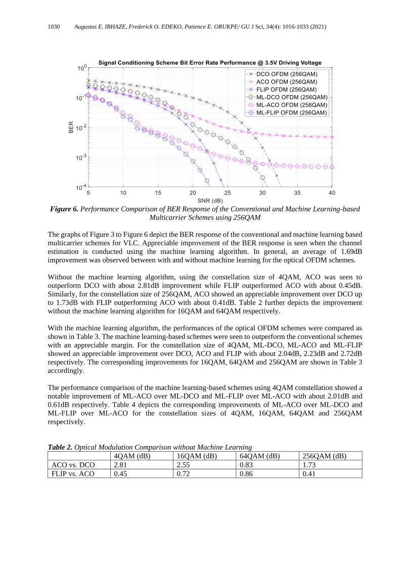
Figure 6. Performance Comparison of BER Response of the Conventional and Machine Learning-based
Multicarrier Schemes using 256QAM
The graphs of Figure 3 to Figure 6 depict the BER response of the conventional and machine learning based
multicarrier schemes for VLC. Appreciable improvement of the BER response is seen when the channel
estimation is conducted using the machine learning algorithm. In general, an average of 1.69dB
improvement was observed between with and without machine learning for the optical OFDM schemes.
Without the machine learning algorithm, using the constellation size of 4QAM, ACO was seen to
outperform DCO with about 2.81dB improvement while FLIP outperformed ACO with about 0.45dB.
Similarly, for the constellation size of 256QAM, ACO showed an appreciable improvement over DCO up
to 1.73dB with FLIP outperforming ACO with about 0.41dB. Table 2 further depicts the improvement
without the machine learning algorithm for 16QAM and 64QAM respectively.
With the machine learning algorithm, the performances of the optical OFDM schemes were compared as
shown in Table 3. The machine learning-based schemes were seen to outperform the conventional schemes
with an appreciable margin. For the constellation size of 4QAM, ML-DCO, ML-ACO and ML-FLIP
showed an appreciable improvement over DCO, ACO and FLIP with about 2.04dB, 2.23dB and 2.72dB
respectively. The corresponding improvements for 16QAM, 64QAM and 256QAM are shown in Table 3
accordingly.
The performance comparison of the machine learning-based schemes using 4QAM constellation showed a
notable improvement of ML-ACO over ML-DCO and ML-FLIP over ML-ACO with about 2.01dB and
0.61dB respectively. Table 4 depicts the corresponding improvements of ML-ACO over ML-DCO and
ML-FLIP over ML-ACO for the constellation sizes of 4QAM, 16QAM, 64QAM and 256QAM
respectively.
Table 2. Optical Modulation Comparison without Machine Learning
4QAM (dB) 16QAM (dB) 64QAM (dB) 256QAM (dB)
ACO vs. DCO 2.81 2.55 0.83 1.73
FLIP vs. ACO 0.45 0.72 0.86 0.41

1031 Augustus E. IBHAZE, Frederick O. EDEKO, Patience E. ORUKPE/ GU J Sci, 34(4): 1016-1033 (2021)
Table 3. Optical Modulation Comparison with and without Machine Learning
4QAM (dB) 16QAM (dB) 64QAM (dB) 256QAM (dB)
ML-DCO vs.
DCO
2.04 2.01 1.96 1.96
ML-ACO vs.
ACO
2.23 2.25 2.46 2.36
ML-FLIP vs.
FLIP
2.72 2.25 2.20 2.15
Table 4. Optical Modulation Comparison with Machine Learning
4QAM (dB) 16QAM (dB) 64QAM (dB) 256QAM (dB)
ML-ACO vs. ML-DCO 2.01 2.46 0.45 1.99
ML-FLIP vs. ML-ACO 0.61 0.76 1.04 1.17
For the constellation size of 4QAM, the relative and absolute errors were seen to be 0.06922, 0.00513 and
0.00664 RMSEs and 1.415x1050, 39516.46 and 1432.46 MAPEs for ML-DCO, ML-ACO and ML-FLIP
respectively with an R-score of 0.999999. With 16QAM constellation, 0.07521, 0.00991 and 0.01196
RMSEs; 2.15x1064, 3402944.28 and 9423.52 MAPEs for ML-DCO, ML-ACO and ML-FLIP respectively
and 0.999992 R-score was observed. As higher constellation sizes were used, 0.08062, 0.01352 and
0.01561 RMSEs; 4.01x1057, 4.11x1024 and 6415.20 MAPEs for ML-DCO, ML-ACO and ML-FLIP
respectively and 0.999999 R-score was recorded for 64QAM and 0.09034, 0.02668 and 0.02747 RMSEs;
4.13x1060, 4.53x10²³ and 9197.74 MAPEs for ML-DCO, ML-ACO and ML-FLIP respectively and with
0.98987 R-score for 256QAM. Tables 5 and 6 depict the summary of the relative and absolute errors for
the conventional and machine learning-based schemes.
The machine learning-based schemes were seen to show performance superiority relative to the
conventional schemes with remarkable reduction in both relative and absolute errors. With such
improvement in the BER response relative to increasing SNR values, the schemes invariably will
outperform the conventional schemes with higher throughput as fewer bits will be transmitted in error.
Table 5. RMSE Performance measure of the multicarrier schemes
RMSE
4QAM 16QAM 64QAM 256QAM
DCO 0.11997 0.13221 0.14361 0.15890
ML-DCO 0.06922 0.07521 0.08062 0.09034
ACO 0.02475 0.03184 0.04697 0.07149
ML-ACO 0.00513 0.00991 0.01352 0.02668
FLIP 0.02432 0.03168 0.04594 0.06918
ML-FLIP 0.00664 0.01196 0.01561 0.02747
Table 6. MAPE Performance measure of the multicarrier schemes
MAPE
4QAM 16QAM 64QAM 256QAM
DCO 2.10687E+65 2.99112E+65 3.71759E+58 4.10066E+61
ML-DCO 1.41518E+50 2.1536E+64 4.01499E+57 4.13346E+60
ACO 434959.8513 31435460.06 4.1057E+25 4.5317E+24
ML-ACO 39516.45752 3402944.275 4.1123E+24 4.535E+23
FLIP 15081.32384 86388.83977 63667.80671 1142285658
ML-FLIP 1432.456583 9423.517892 6415.200862 9197.736619

1032 Augustus E. IBHAZE, Frederick O. EDEKO, Patience E. ORUKPE/ GU J Sci, 34(4): 1016-1033 (2021)
4. CONCLUSION
It was observed that the BER response improved as a result of the adaptive learning process of the machine
learning algorithm for all multicarrier modulation schemes. The adoption of the proposed machine learning-
based multicarrier modulation (MLMM) scheme can be adopted depending on the spectral and power
efficiency requirement as it outperformed its conventional counterpart.
ACKNOWLEDGEMENT
The authors gratefully acknowledge the sponsorship of this research by the Petroleum Technology
Development Fund (PTDF) under the grant award number P4567720076521527.
CONFLICTS OF INTEREST
No conflict of interest was declared by the authors.
REFERENCES
[1] Feng, S., Zhang, R., Xu, W., Hanzo, L., "Multiple Access Design for Ultra-Dense VLC Networks:
Orthogonal vs Non-Orthogonal ", IEEE Transactions on Communications, 67(3): 2218 - 2231,
(2019).
[2] Agboje, O. E., Idowu-Bismark, O. B., Ibhaze, A. E., "Comparative Analysis of Fast Fourier
Transform and Discrete Wavelet Transform Based MIMO-OFDM", International Journal on
Communications Antenna and Propagation (I.Re.C.A.P.), 7(2): 168 - 175, (2017).
[3] Ndujiuba C. U., Ibhaze, A. E., "Dynamic Differential Modulation of Sub-Carriers in OFDM”, Journal
of Wireless Networking and Communications, 6(1): 21-28, (2016).
[4] Ibhaze, A. E., Orukpe, P. E., Edeko, F. O., "Li-Fi Prospect in Internet of Things Network", in: J.
Kacprzyk (Ed.), FICC2020, Advances in Intelligent Systems and Computing. Cham, Switzerland:
Springer Nature Switzerland AG, 1129: 272–280, (2020).
[5] Huang, X., Yang, F., Zhang, H., Ye, J., Song, J., "Subcarrier and Power Allocations for Dimmable
Ehanced ADO-OFDM with Iterative Interference Cancellation", IEEE Access, 7: 28422 - 28435,
(2019).
[6] Shannon, C. E., "A Mathematical Theory of Communication", The Bell System Technical Journal,
27(3, 4): 379–423, 623–656, (1948).
[7] Ibhaze, A. E., Orukpe, P. E. and Edeko, F. O., "High-Capacity Data Rate System: Review of Visible
Light Communications Technology", Journal of Electronic Science and Technology. DOI:
https://doi.org/10.1016/j.jnlest.2020.100055, (2020).
[8] Cover T. M. and Thomas, J. A., Elements of Information Theory, 2nd ed. Hoboken, New Jersey:
John Wiley & Sons, Inc., (2006).
[9] Tan, J., Wang, Z., Wang, Q., Dai, L., "BICM-ID scheme for clipped DCO-OFDM in visible light
communications", Optics Express, 24(5): 4573 - 4581, (2016).
[10] Nee, R., Awater, G., Morikura, M., Takanashi, H., Webster, M., Halford, K. W., "New High-Rate
Wireless LAN Standards", IEEE Communications Magazine, 37(12): 82 - 88, (1999).
1033 Augustus E. IBHAZE, Frederick O. EDEKO, Patience E. ORUKPE/ GU J Sci, 34(4): 1016-1033 (2021)
[11] Hu, W. W., "PAPR Reduction in DCO-OFDM Visible Light Communication Systems Using
Optimized Odd and Even Sequences Combination", IEEE Photonics Journal, 11(1): 790115, (2019).
[12] Proakis, J. G., Digital Communications, 4th ed, McGrawHill, (2000).
[13] Kahn, J. M., Barry, J. R., "Wireless Infrared Communications", Proceedings of the IEEE, 85(2): 65
- 298, (1997).
[14] Armstrong, J. "OFDM for optical communications", IEEE Journal of Light Wave Technology, 27(3):
189 - 204, (2009).
[15] Devasmitha Dissanayake, S., Armstrong, J., "Comparison of ACO-OFDM, DCO-OFDM and ADO-
OFDM in IM/DD Systems", IEEE Journal of Lightwave Technology, 31(7): 1063 - 1072, (2013).
[16] Chen, L., Krongold, B., Evans, J. "Performance Analysis for Optical OFDM Transmission in Short-
Range IM/DD Systems", IEEE Journal of Lightwave Technology, 30(7): 974 - 983, (2012).
[17] Chung, S. T., Goldsmith, A. J., "Degrees of Freedom in Adaptive Modulation: A Unified View”,
IEEE Transactions on Communications, 49(9): 1561 - 1571, (2001).
[18] Fernando, N., Hong, Y., Viterbo, E., "Flip-OFDM for Optical Wireless Communications”, in IEEE
Information Theory Workshop, Paraty, Brazil, 5 – 9, (2011).
[19] Tsonev, D., Haas, H., "Avoiding spectral efficiency loss in unipolar OFDM for optical wireless
communication", in IEEE International Conference on Communications (ICC), Sydney, NSW,
Australia, 3336 – 3341, (2014).
[20] Wu, L., Zhang, Z., Dang, J., Wang, J., Liu, H., "Polarity Information Coded Flip-OFDM for Intensity
Modulation Systems”, IEEE Communications Letters, 20(8): 1089 - 7798, (2016).
[21] Castel, T., Lemey, S., Agneessens, S., Torre, P. V., Rogier, H., Oestges, C., "Adaptive subcarrier
modulation for indoor public safety body-to-body networks", in IEEE 10th European Conference on
Antennas and Propagation (EuCAP), Davos, Switzerland, 1-5, (2016). [22] Ibhaze, A. E., Orukpe P. E., Edeko, F. O., "Visible Light Channel Modeling for High-data
Transmission in the Oil and Gas Industry", Journal of Science and Technology, 12(2): 46-54, (2020).
[23] Nachbaur, O., "White LED Power Supply Design Techniques", Texas Instruments Incorporated,
Dallas, Texas, (2003).