journal of structural geology - ceri - university of memphis · we also noted that many...
TRANSCRIPT
lable at ScienceDirect
Journal of Structural Geology 75 (2015) 49e59
Contents lists avai
Journal of Structural Geology
journal homepage: www.elsevier .com/locate/ jsg
Spatial arrangement of d�ecollements as a control on the developmentof thrust faults
Lian Feng a, *, Mervin J. Bartholomew a, Eunseo Choi b
a Department of Earth Sciences, The University of Memphis, Memphis, TN 38152, USAb Center for Earthquake Research and Information, The University of Memphis, Memphis, TN 38152, USA
a r t i c l e i n f o
Article history:Received 12 August 2014Received in revised form24 February 2015Accepted 5 March 2015Available online 21 March 2015
Keywords:Numerical modelingD�ecollementThrust faultRamp-flatImbricateDuplex
* Corresponding author. Tel.: þ1 901 678 1421.E-mail addresses: [email protected] (L. Fen
(M.J. Bartholomew), [email protected] (E. Choi).
http://dx.doi.org/10.1016/j.jsg.2015.03.0020191-8141/© 2015 Elsevier Ltd. All rights reserved.
a b s t r a c t
We used two-dimensional finite element models to explore different configurations of weak layers inundeformed sedimentary sequences to investigate the occurrence of three characteristic types of thrustconfigurations: ramp-flat; imbricate; and duplex. In our models, we embedded two low-friction weaklayers with a finite spatial extent in a sequence of stronger rock. These two weak layers were initiallyhorizontal, were separated vertically by 1 km, and were arranged in three different relative positions toeach other. When the models were deformed and these weak layers developed into d�ecollements, theyinteracted to produce one of the three types of thrust faults as a function of their initial configurations.When the tips of weak layers were separated by a large gap (>10 km), only the lower-level d�ecollementbecame active, producing imbricate thrusts. When the two weak layers overlapped for a large distance(>10 km), they simultaneously became active d�ecollements, producing duplexes in the overlapped zone.When the gap or overlap was small (<5 km), the two weak layers also simultaneously became actived�ecollements but their tips linked up to form a ramp-flat geometry. These results suggest that thrustgeometry is highly sensitive to the initial arrangement of d�ecollements.
© 2015 Elsevier Ltd. All rights reserved.
1. Introduction
This study grew out of regional mapping (e.g. Bartholomew andLowery, 1979; Bartholomew et al., 1981; Schultz, 1986, 1988;Bartholomew, 1987; Bartholomew and Brown, 1992; Schultz andBartholomew, 2009, 2010) and outcrop-scale studies (e.g. Schultz,1979; Bartholomew et al., 1980, 1982; Gray, 1981; House andGray, 1982; Simon and Gray, 1982; Schultz, 1986; Onasch andDunne, 1993; Couzens et al., 1993; Bartholomew et al., 1994;Whitaker and Bartholomew, 1999; Spraggins and Dunne, 2002;Bartholomew and Whitaker, 2010) in the Roanoke recess of theAppalachian fold-and-thrust belt in an effort to understand whysome thin, weak layers developed into intensely deformed zoneswhereas, elsewhere the weak layers were significantly lessstrained. In this paper, we used the terms “weak” or “incompetent”to describe rocks that have low frictional strength and cohesionrelative to “strong” or “competent” rocks. We reserved the term“d�ecollement” for a gliding zone of accumulated high shear strain.
Earlymodeling by Apperson and Bartholomew (1992) examinedthe relationship between the intensity of deformation of a thinweak unit, beneath a flat between two ramps, and the length of thatflat. Their preliminary results suggested that:
1. ramps functioned independently for a flat-length of 10 km;2. ramps merged into a single ramp for a flat-length of 1 km;3. but for a flat-length of 5 km, the thinweak layer beneath the flat
extended for the length of the flat as a highly strained zone.
The last result was consistent with extensive duplexing in aweak zone, observed in outcrops in Middle-Upper Ordovicianstrata, below a flat in the above-cited work in the recess (e.g. Gray,1981; Simon and Gray, 1982; Couzens and Dunne, 1994). Addi-tionally, Smart et al. (1997) showed that, farther north in the centralAppalachians, 75% of the shortening of the roof sequence, above aweak zone in Middle-Upper Ordovician strata, was accommodatedby micro- and meso-scale structures during duplex emplacement.Similarly, the weak zone in Silurian salt, still farther north inPennsylvania, allowed decoupling of the roof sequence duringemplacement of the Cambrian-Ordovician duplexes (Gwinn, 1964,1970; Nickelsen, 1988).
L. Feng et al. / Journal of Structural Geology 75 (2015) 49e5950
We also noted that many fold-and-thrust belts have more thanone weak zone above the basal d�ecollement, and they havedeveloped into d�ecollements at different depths (e.g. Price andFermor, 1985; Williams and Dixon, 1985; Wilson and Schumaker,1992; Belotti et al., 1995). Weak zones may extend across theentire fold-and-thrust belt but are more likely to be less continuousdue to syn-orogenic changes in depositional environments. How-ever, most previous studies, that were concerned about de-formations in a thrust system, considered only one weak layer oralternating continuous weak layers extending across the entirewidth of a fold-and-thrust belt (e.g. Buiter et al., 2006; Selzer et al.,2007; Konstantinovskaya and Malavieille, 2011; Simpson, 2011;Ruh et al., 2012). These models provided valuable insights ondevelopment of an entire thrust wedge but such “layer-cake”models clearly precluded investigation on the evolution of a thrustsystem with multiple discontinuous d�ecollements.
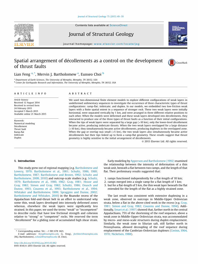
The presence of multiple discontinuous d�ecollements in a fold-and-thrust belt and their potential importance for local thrust ge-ometry led us to question how gaps and overlaps of weak zonesdetermine thrust geometry. Three major types of thrust geometriesfound in fold-and-thrust belts are:
� a ramp-flat structure (Fig. 1a), a thrust with a stair-step trajec-tory (Rich, 1934);
� an imbricate thrust system (Fig. 1b) that consists of sequentiallyformed subparallel thrust faults that develop from a commonbasal d�ecollement (Boyer and Elliott, 1982);
� a duplex (Fig. 1c) that forms when splays asymptotically curveupward and link with a higher-level d�ecollement rather thanterminate up-section (Boyer and Elliott, 1982).
A fold-and-thrust belt typically contains complex thrust systemsthat exhibit all three geometries and this observation forms thebasis for our hypothesis that the type of thrust geometry is deter-mined by the local configuration of discontinuous d�ecollements.Appearance of all three geometries in fold-and-thrust belts wasdocumented in the Appalachians (e.g. Rich, 1934; Rodger, 1950;Mitra, 1986; Bartholomew, 1987; Evans, 1989), the Canadian Rock-ies (e.g. Dahlstrom, 1970; Price, 1981), the Alps (e.g. Ramsay, 1981;
Fig. 1. Diagrams depicting three types of thrusts. (a) Ramp-flat geometry modified from RShaded layers demarcate d�ecollement levels. Black lines and arrows indicate faults and the
Boyer and Elliott, 1982) and Taiwan (e.g. Suppe, 1980; Davis et al.,1983). Here we choose the central Appalachians to illustrate howall threemay be found in transects that changewestward across thefold-and-thrust belt:
� from where the imbricated, far-travelled (~50 km) Blue Ridgeand North Mountain sheets overlie a duplicated section oflower-to-middle Paleozoic strata (e.g. Evans, 1989, 2010);
� to the extensive blind duplex (used by Boyer and Elliott, 1982) ofthick, strong, Cambrian-Ordovician carbonates that ends withthe Wills Mountain structure (e.g. Evans, 1989; Wilson, 1989;Wilson and Shumaker, 1992; Evans, 2010);
� where, imbricates then cut across thin, but strong, near-verticalSilurian quartzite which forms the structural front of the fold-and-thrust belt (e.g. Evans, 1989, 2010);
� to the foreland where a few ramp-flat structures cut upwardfrom middle Ordovician to Devonian strata (e.g. Evans, 1989,2010) and megascopic and microscopic structures account for10e15% shortening (Engelder and Engelder, 1977; Dean et al.,1988; Smart et al., 1997; Spraggins and Dunne, 2002; Evans,2010).
Physical and numerical models have long been used to studydeformation in fold-and-thrust belts (e.g. Erickson, 1995; Smartet al., 1999; Smart and Couzens-Schultz, 2001; Buiter et al., 2006;Selzer et al., 2007; Stockmal et al., 2007; Simpson, 2009; Kon-stantinovskaya and Malavieille, 2011; Ruh et al., 2012). Somemodeling studies particularly addressed structural evolution of afold-and-thrust belt with single versus multiple and viscous versusfrictional d�ecollements. Regardless of technical differences amongmodeling methods, the following have been commonly found inthe results: (1) Formation of in-sequence forelandward-propagatedthrusts accommodated most strain whether the rheology ofd�ecollement was frictional or viscous (Buiter et al., 2006; Selzeret al., 2007; Stockmal et al., 2007; Simpson, 2009;Konstantinovskaya and Malavieille, 2011); (2) backward-vergingthrusts formed in thrust belts over a viscous d�ecollement(Simpson, 2009; Ruh et al., 2012); (3) more than one d�ecollementproduced more complex structures like fault-bend folds, duplexes,
ich (1934). (b) Imbricate thrusts modified from Boyer and Elliott (1982). (c) Duplexes.ir sense of motion.
L. Feng et al. / Journal of Structural Geology 75 (2015) 49e59 51
fault propagation folds, tectonic underplating and antiformalstacking (Stockmal et al., 2007; Konstantinovskaya and Malavieille,2011; Ruh et al., 2012).
Multiple discontinuous d�ecollements in a fold-and-thrust beltand their potential importance for thrust geometry motivated ourinvestigation on the correspondence between thrust geometry andweak layers in an undeformed rock sequence. Through systematiccontrol of theweak layer configuration in the numerical models, weoffer insights into which initial configurations of d�ecollements areresponsible for the relative abundance of ramp-flats, imbricate fansand duplexes in thrust systems.
2. Numerical method
2.1. Numerical solver
We used DynEarthSol2D (Choi et al., 2013), a two-dimensional,explicit, unstructured finite-element solver. Being open source, it isavailable at http://bitbucket.org/tan2/dynearthsol2. DynEarth-Sol2D is built upon the same set of governing equations and solu-tion procedures as for FLAC (Cundall and Board, 1988; Poliakovet al., 1994; Lavier et al., 2000). The most useful new feature ofDynEarthSol2D is the flexibility in meshing that is enabled by theuse of unstructured grids. Unlike its predecessors, DynEarthSol2Dcan easily refine a mesh around a fine-scale structure. It also candynamically refine and coarsen the initial mesh as strain localizesin fault zones (Choi et al., 2013). These features render this codesuitable for modeling deformations that involve formation andevolution of multiple faults. All models presented in this paperwere run on a cluster at the High Performance ComputationalCenter of the University of Memphis. Each compute node of thecluster has an AMD Dual Opteron 8356 (Shanghai) 2.5 GHz QuadCore and 32 GB (16� 2 GB) DDR2-667 RAM. Eachmodel was run ona single core and took about 96 h to generate 10 km of shortening inour model setting.
2.2. Model geometry
For the sake of keeping models simple, yet geologically relevant,we imposed the following constraints, which are based on knowncharacteristics of fold-and-thrust belts:
1. The belts are thin-skinned, i.e., thrusts are entirely confined tosedimentary rocks above the basement complex.
2. The model configuration is consistent with a layered sedimen-tary sequence that was deposited prior to horizontal shortening.
3. The presence of multiple weak layers within the rock sequenceis common (Rich, 1934; Mitra, 1986; Bartholomew, 1987; Evans,1989).
4. Perturbations such as fault shape, stratigraphy, pore fluid pres-sure, folding, and surface slope are not necessary for develop-ment of thrust faults (Panian and Wiltschko, 2004).
We constrainedmechanical stratigraphy in our models based onthe simplified Paleozoic sedimentary sequence from the northernend of the southern Appalachian fold-and-thrust belt(Bartholomew, 1987). Here, a regional basal detachment is in theCambrian Rome Formation and is overlain sequentially by: 1)1300 m of relatively strong Cambro-Ordovician shelf carbonates; 2)400 m of middle to upper Ordovician calcareous mudstones/silt-stones; 3) 400 m of extremely strong Silurian quartz arenites; 4)1100 m of Devonian mudstones/siltstones and interlayered sand-stones; 5) >1500 m of Mississippian sandstone-dominated clasticrocks. Thus, these lower Paleozoic rocks are divisible into threecompetent lithotectonic units that are separated by Ordovician and
Devonian incompetent units (mudstones/siltstones) and the spatialextent of these two incompetent units do not entirely overlap eachother (Harris and Milici, 1977; Bartholomew, 1987; Evans, 1989).
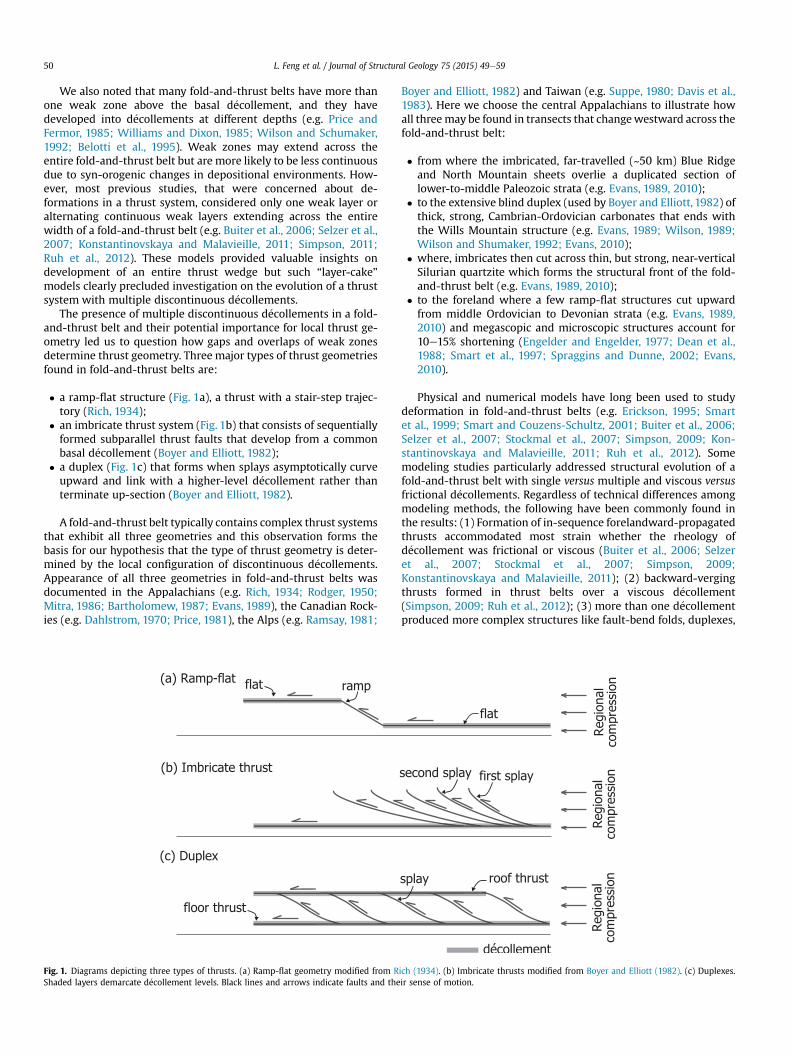
Models begin with a rectangular domain comprised of a staticbase with a deformable overlying layered sequence (Fig. 2). Thebase, corresponding to marker layer 3 in Fig. 2, is a 2 km-thick layerof competent rock and is fixed both horizontally and verticallyalong the bottom as well as along the right- and left-handboundaries. Above the base is a 6 km-thick layer of competentrock in which two different colors are used to show an alternatingsequence of marker layers as a proxy for bedding in every model.Two 500 m-thick weak layers are at depths of ~4.5 and ~6 km,respectively. The domain is discretized into triangular elementswith a ~180 m long edge on average but smaller elements arecreated when new nodes are inserted into shear bands duringremeshing (Choi et al., 2013). As a result, elements within a shearband have an average edge length of 68 m.
Both the vertical and horizontal spacing between the weaklayers are adjustable. However, our preliminary tests showed thatthe influence of vertical spacing on thrust geometry is not as sig-nificant as the horizontal spacing (compare Fig. A1b with Fig. A1a).Therefore, for the models presented here, the vertical spacing be-tween the weak layers is held constant at 1 km. The horizontalspacing (DL) is defined as L1�L2, where L1 is the location of the rightend of the shallower incompetent layer, measured from the leftboundary of the domain, and L2 is the location of the left end of thedeeper incompetent layer. With these definitions, a positive valueof DL corresponds to overlapping incompetent layers whereas anegative value corresponds to a gap.
2.3. Material model
Rocks start to experience permanent deformation when differ-ential stress exceeds a certain yield condition. Faults or fault zonescan be considered as one of the localized forms of permanentdeformation. Strength of brittle materials like rock, by definition ofbrittleness (e.g. pp. 80, Jaeger and Cook, 1976), degrades withaccumulating permanent strain. To represent such behaviors ofrocks in our continuum models, we employ the non-associatedMohr-Coulomb plasticity model with strain weakening. Thisconstitutive model allows for localization of plastic strain in theform of shear bands that behave like faults (e.g. Buck, 1988; Lavieret al., 2000; Ellis et al., 2004; Ruh et al., 2012). Although formationof shear bands can occur without strain weakening (e.g.Vardoulakis, 1980), we enforced strain weakening to uncondition-ally induce the formation of shear bands. In our formulation ofstrain weakening, plastic parameters such as friction angle andcohesion are linearly reduced as plastic strain increases (e.g. Lavieret al., 2000; Ellis et al., 2004; Ruh et al., 2012).
The mechanical lithology in our models is categorized asincompetent and competent layers only, and identical materialproperties are assigned to each type. Therefore, Cambro-Ordovicianshelf carbonates and Silurian quartz-arenites are classified ascompetent layers, likewise, Devonian mudstones/siltstones andupper Ordovician calcareous mudstones/siltstones are treated asthe same type of incompetent rock.
Our model sensitivity tests suggested that deformation behav-iors are not significantly affected by geologically reasonable varia-tions in elastic moduli and density (compare Figs. A1c and A1dwithFig. A1a). Thus we used a constant shear modulus and bulkmodulus for all lithologies in the models: 3 GPa and 5 GPa,respectively.
For plasticity, the cohesion and friction angle of competentlayers are subjected to strainweakening and decrease linearly fromC0 ¼ 40 MPa and 40 ¼ 30� to their minima, 10% of C0 and 50% of 40,
Fig. 2. Model setup and boundary conditions. The dotted box outlines the part of the model domain shown in subsequent figures. See text for further explanation.
L. Feng et al. / Journal of Structural Geology 75 (2015) 49e5952
respectively, with increasing plastic strain up to 10. Although aplastic strain measure of 10 seems high, it is not extreme for shearbands that are dynamically refined as in our models. The nominalvalue of plastic strain is equivalent to the critical fault offset of~2 km for the ~200 m-wide shear bands (element size of 68 m � 3elements composing a shear band) of our models according to theformulation proposed by Lavier et al. (2000). They showed thatdefining the weakening rate in terms of the critical offset ratherthan plastic strain effectively eliminated element size-dependentbehaviors for shear bands. The critical offset of 2 km used in thisstudy is within the range of values adopted in other studies (e.g.Smart et al., 1999; Lavier et al., 2000; Stockmal et al., 2007).Cohesion and friction angles employed for competent layers in ourmodels are within the general range reported in experimental data(e.g. Zoback, 2007). D�ecollements in shale are often represented byfrictionally weak layers with a much smaller Mohr-Coulomb failurecriterion than the overlying material. So, the friction angle is fixedat 1� and cohesion is zero for weak layers in this study, which arecomparable to those values used in previously similar work (Selzeret al., 2007; Stockmal et al., 2007; Ruh et al., 2012). Some numericalmodeling experiments showed that models with lower cohesionfor thrust systems are more comparable to analogue models (e.g.Ellis et al., 2004). Thus cohesion values for incompetent layers infrictional models are often smaller than the suggested values forshale layers in physical experiments (e.g. Colmenares and Zoback,2002). A complete list of material properties used in this study isgiven in Table 1.
2.4. Initial and boundary conditions
A gravitational body force is always applied and a lithostaticstress state is assumed as the initial condition in our models. Alongthe right hand boundary above the base, both a constant horizontal
Table 1Material properties used for mechanical stratigraphy.
Parameter Description
G Shear Modulus (GPa)K Bulk Modulus (GPa)C0 Initial Cohesion (MPa)C1 Reduced Cohesion (MPa)40 Initial Friction angle (�)41 Reduced Friction angle (�)Ɛp Critical plastic strainJ Dilation angle (�)r Density (kg/m3)
velocity (vx ¼ �1 cm/yr) and a zero vertical velocity (vz ¼ 0) areapplied. The horizontal velocity is linearly reduced to zero from thetop to the bottom of the right end of the lower weak layer. The leftboundary above the base has a free-slip condition (Fig. 2). The ve-locity boundary condition applies an incrementally increasingdisplacement boundary condition. Therefore, time and velocity donot have meaning for our models individually, but the product ofthem, i.e., displacement, does. Syndeformational exhumation re-sults in sediments deposited toward the foreland during and afterthe orogenic process (e.g. Dahlen and Barr, 1989), and manymodeling studies showed that surface process plays an importantrole on deformation in the foreland fold-and-thrust belts (e.g.Bonnet et al., 2007; Malavieille, 2010). In this study, a diffusion-liketopographic smoothing model (Culling, 1960) is applied to the topboundary. Surface processes approximated by this model have beentaken into account in previous studies on thrust systems such asSelzer et al. (2007) and Ruh et al. (2012). Culling's model assumesthat the time rate of change of topography is proportional to thesurface curvature, yielding the following diffusion equation:
vhvt
¼ kV2h
where h is the surface topography and k is the transport coefficient.The value of k is 3.15 m2/yr in all of our models, which is in therange of 0.05e5 m2/yr (Allen, 1997; Kühni and Pfiffner, 2001).
3. Results
We ran 9 models where DL varied from � 20 to 20 km at 5-kmincrements. We displayed model results with up to 10 km ofbackstop displacement, where the thrusting style is unambiguously
Weak layer Strong layer (marker layer 1e3)
3 35 50 400 41 301 150.1 100 0
2500 2600
L. Feng et al. / Journal of Structural Geology 75 (2015) 49e59 53
identified. We describe three models in detail that each clearlyreproduced one of the three thrusting styles.
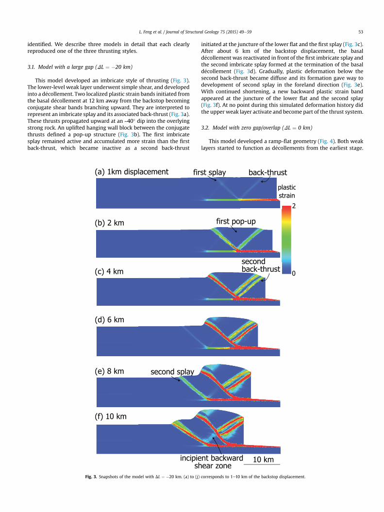
3.1. Model with a large gap (DL ¼ �20 km)
This model developed an imbricate style of thrusting (Fig. 3).The lower-level weak layer underwent simple shear, and developedinto a d�ecollement. Two localized plastic strain bands initiated fromthe basal d�ecollement at 12 km away from the backstop becomingconjugate shear bands branching upward. They are interpreted torepresent an imbricate splay and its associated back-thrust (Fig. 3a).These thrusts propagated upward at an ~40� dip into the overlyingstrong rock. An uplifted hanging wall block between the conjugatethrusts defined a pop-up structure (Fig. 3b). The first imbricatesplay remained active and accumulated more strain than the firstback-thrust, which became inactive as a second back-thrust
Fig. 3. Snapshots of the model with DL ¼ �20 km. (a) to (j)
initiated at the juncture of the lower flat and the first splay (Fig. 3c).After about 6 km of the backstop displacement, the basald�ecollement was reactivated in front of the first imbricate splay andthe second imbricate splay formed at the termination of the basald�ecollement (Fig. 3d). Gradually, plastic deformation below thesecond back-thrust became diffuse and its formation gave way todevelopment of second splay in the foreland direction (Fig. 3e).With continued shortening, a new backward plastic strain bandappeared at the juncture of the lower flat and the second splay(Fig. 3f). At no point during this simulated deformation history didthe upper weak layer activate and become part of the thrust system.
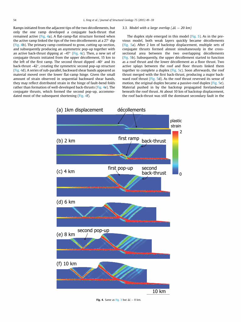
3.2. Model with zero gap/overlap (DL ¼ 0 km)
This model developed a ramp-flat geometry (Fig. 4). Both weaklayers started to function as d�ecollements from the earliest stage.
corresponds to 1e10 km of the backstop displacement.
L. Feng et al. / Journal of Structural Geology 75 (2015) 49e5954
Ramps initiated from the adjacent tips of the two d�ecollements, butonly the one ramp developed a conjugate back-thrust thatremained active (Fig. 4a). A flat-ramp-flat structure formed whenthe active ramp linked the tips of the two d�ecollements at a 27� dip(Fig. 4b). The primary ramp continued to grow, cutting up-section,and subsequently producing an asymmetric pop-up together withan active back-thrust dipping at ~47� (Fig. 4c). Then, a new set ofconjugate thrusts initiated from the upper d�ecollement, 15 km tothe left of the first ramp. The second thrust dipped ~40� and itsback-thrust ~42�, creating the symmetric second pop-up structure(Fig. 4d). A series of sub-parallel, backward shear bands appeared asmaterial moved over the lower flat-ramp hinge. Given the smallamount of strain observed in sequential backward shear bands,they may reflect distributed strain in the hinge of fault-bend foldsrather than formation of well-developed back-thrusts (Fig. 4e). Theconjugate thrusts, which formed the second pop-up, accommo-dated most of the subsequent shortening (Fig. 4f).
Fig. 4. Same as Fig. 3
3.3. Model with a large overlap (DL ¼ 20 km)
The duplex style emerged in this model (Fig. 5). As in the pre-vious model, both weak layers quickly became d�ecollements(Fig. 5a). After 2 km of backstop displacement, multiple sets ofconjugate thrusts formed almost simultaneously in the cross-sectional area between the two overlapping d�ecollements(Fig. 5b). Subsequently, the upper d�ecollement started to functionas a roof thrust and the lower d�ecollement as a floor thrust. Twoactive splays between the roof and floor thrusts linked themtogether to complete a duplex (Fig. 5c). Soon afterwards, the roofthrust merged with the first back-thrust, producing a major back-ward roof thrust (Fig. 5d). As the roof thrust reversed its sense ofmotion, the original duplex became a passive-roof duplex (Fig. 5e).Material pushed in by the backstop propagated forelandwardbeneath the roof thrust. At about 10 km of backstop displacement,the roof back-thrust was still the dominant secondary fault in the
but DL ¼ 0 km.
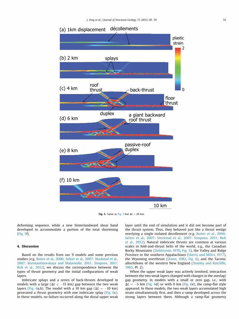
Fig. 5. Same as Fig. 3 but DL ¼ 20 km.
L. Feng et al. / Journal of Structural Geology 75 (2015) 49e59 55
deforming sequence, while a new hinterlandward shear banddeveloped to accommodate a portion of the total shortening(Fig. 5f).
4. Discussion
Based on the results from our 9 models and some previousstudies (e.g. Buiter et al., 2006; Selzer et al., 2007; Stockmal et al.,2007; Konstantinovskaya and Malavieille, 2011; Simpson, 2011;Ruh et al., 2012), we discuss the correspondence between thetypes of thrust geometry and the initial configurations of weaklayers.
Imbricate splays and a series of back-thrusts developed inmodels with a large (DL � �15 km) gap between the two weaklayers (Fig. 6a,b). The model with a 10 km gap (DL ¼ �10 km)generated a thrust geometry with one imbricate splay (Fig. 6c).In these models, no failure occurred along the distal upper weak
layer until the end of simulation and it did not become part ofthe thrust system. Thus, they behaved just like a thrust wedgeoverlying a single isolated d�ecollement (e.g. Buiter et al., 2006;Selzer et al., 2007; Stockmal et al., 2007; Simpson, 2011; Ruhet al., 2012). Natural imbricate thrusts are common at variousscales in fold-and-thrust belts of the world, e.g., the CanadianRocky Mountains (Dahlstrom, 1970, Fig. 3), the Valley and RidgeProvince in the southern Appalachians (Harris and Milici, 1977),the Wyoming overthrust (Dixon, 1982, Fig. 6), and the Taconicallochthons of the western New England (Stanley and Ratcliffe,1985, Pl. 2).
When the upper weak layer was actively involved, interactionbetween the twoweak layers changed with changes in the overlap/gap geometry. In models with a small or zero gap, i.e., withDL ¼ �5 km (Fig. 6d) or with 0 km (Fig. 6e), the ramp-flat styleappeared. In these models, the two weak layers accumulated highstrain simultaneously first, and then a ramp developed across thestrong layers between them. Although a ramp-flat geometry
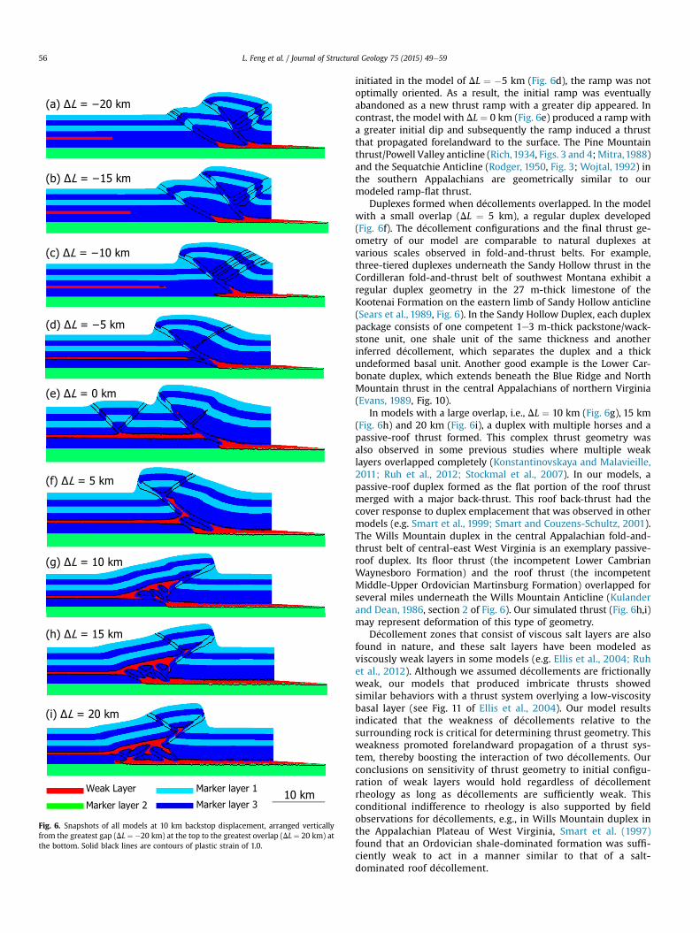
Fig. 6. Snapshots of all models at 10 km backstop displacement, arranged verticallyfrom the greatest gap (DL ¼ �20 km) at the top to the greatest overlap (DL ¼ 20 km) atthe bottom. Solid black lines are contours of plastic strain of 1.0.
L. Feng et al. / Journal of Structural Geology 75 (2015) 49e5956
initiated in the model of DL ¼ �5 km (Fig. 6d), the ramp was notoptimally oriented. As a result, the initial ramp was eventuallyabandoned as a new thrust ramp with a greater dip appeared. Incontrast, the model with DL ¼ 0 km (Fig. 6e) produced a ramp witha greater initial dip and subsequently the ramp induced a thrustthat propagated forelandward to the surface. The Pine Mountainthrust/Powell Valley anticline (Rich,1934, Figs. 3 and 4;Mitra,1988)and the Sequatchie Anticline (Rodger, 1950, Fig. 3; Wojtal, 1992) inthe southern Appalachians are geometrically similar to ourmodeled ramp-flat thrust.
Duplexes formed when d�ecollements overlapped. In the modelwith a small overlap (DL ¼ 5 km), a regular duplex developed(Fig. 6f). The d�ecollement configurations and the final thrust ge-ometry of our model are comparable to natural duplexes atvarious scales observed in fold-and-thrust belts. For example,three-tiered duplexes underneath the Sandy Hollow thrust in theCordilleran fold-and-thrust belt of southwest Montana exhibit aregular duplex geometry in the 27 m-thick limestone of theKootenai Formation on the eastern limb of Sandy Hollow anticline(Sears et al., 1989, Fig. 6). In the Sandy Hollow Duplex, each duplexpackage consists of one competent 1e3 m-thick packstone/wack-stone unit, one shale unit of the same thickness and anotherinferred d�ecollement, which separates the duplex and a thickundeformed basal unit. Another good example is the Lower Car-bonate duplex, which extends beneath the Blue Ridge and NorthMountain thrust in the central Appalachians of northern Virginia(Evans, 1989, Fig. 10).
In models with a large overlap, i.e., DL ¼ 10 km (Fig. 6g), 15 km(Fig. 6h) and 20 km (Fig. 6i), a duplex with multiple horses and apassive-roof thrust formed. This complex thrust geometry wasalso observed in some previous studies where multiple weaklayers overlapped completely (Konstantinovskaya and Malavieille,2011; Ruh et al., 2012; Stockmal et al., 2007). In our models, apassive-roof duplex formed as the flat portion of the roof thrustmerged with a major back-thrust. This roof back-thrust had thecover response to duplex emplacement that was observed in othermodels (e.g. Smart et al., 1999; Smart and Couzens-Schultz, 2001).The Wills Mountain duplex in the central Appalachian fold-and-thrust belt of central-east West Virginia is an exemplary passive-roof duplex. Its floor thrust (the incompetent Lower CambrianWaynesboro Formation) and the roof thrust (the incompetentMiddle-Upper Ordovician Martinsburg Formation) overlapped forseveral miles underneath the Wills Mountain Anticline (Kulanderand Dean, 1986, section 2 of Fig. 6). Our simulated thrust (Fig. 6h,i)may represent deformation of this type of geometry.
D�ecollement zones that consist of viscous salt layers are alsofound in nature, and these salt layers have been modeled asviscously weak layers in some models (e.g. Ellis et al., 2004; Ruhet al., 2012). Although we assumed d�ecollements are frictionallyweak, our models that produced imbricate thrusts showedsimilar behaviors with a thrust system overlying a low-viscositybasal layer (see Fig. 11 of Ellis et al., 2004). Our model resultsindicated that the weakness of d�ecollements relative to thesurrounding rock is critical for determining thrust geometry. Thisweakness promoted forelandward propagation of a thrust sys-tem, thereby boosting the interaction of two d�ecollements. Ourconclusions on sensitivity of thrust geometry to initial configu-ration of weak layers would hold regardless of d�ecollementrheology as long as d�ecollements are sufficiently weak. Thisconditional indifference to rheology is also supported by fieldobservations for d�ecollements, e.g., in Wills Mountain duplex inthe Appalachian Plateau of West Virginia, Smart et al. (1997)found that an Ordovician shale-dominated formation was suffi-ciently weak to act in a manner similar to that of a salt-dominated roof d�ecollement.
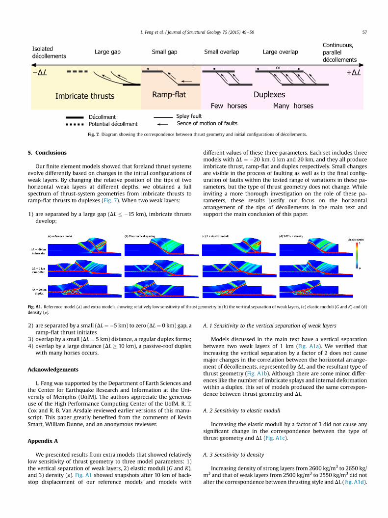
Fig. 7. Diagram showing the correspondence between thrust geometry and initial configurations of d�ecollements.
L. Feng et al. / Journal of Structural Geology 75 (2015) 49e59 57
5. Conclusions
Our finite element models showed that foreland thrust systemsevolve differently based on changes in the initial configurations ofweak layers. By changing the relative position of the tips of twohorizontal weak layers at different depths, we obtained a fullspectrum of thrust-system geometries from imbricate thrusts toramp-flat thrusts to duplexes (Fig. 7). When two weak layers:
1) are separated by a large gap (DL � �15 km), imbricate thrustsdevelop;
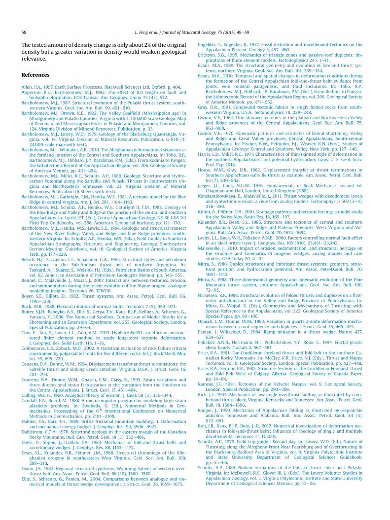
Fig. A1. Reference model (a) and extra models showing relatively low sensitivity of thrust geometry to (b) the vertical separation of weak layers, (c) elastic moduli (G and K) and (d)density (r).
2) are separated by a small (DL¼�5 km) to zero (DL¼ 0 km) gap, aramp-flat thrust initiates
3) overlap by a small (DL ¼ 5 km) distance, a regular duplex forms;4) overlap by a large distance (DL � 10 km), a passive-roof duplex
with many horses occurs.
Acknowledgements
L. Feng was supported by the Department of Earth Sciences andthe Center for Earthquake Research and Information at the Uni-versity of Memphis (UofM). The authors appreciate the generoususe of the High Performance Computing Center of the UofM. R. T.Cox and R. B. Van Arsdale reviewed earlier versions of this manu-script. This paper greatly benefited from the comments of KevinSmart, William Dunne, and an anonymous reviewer.
Appendix A
We presented results from extra models that showed relativelylow sensitivity of thrust geometry to three model parameters: 1)the vertical separation of weak layers, 2) elastic moduli (G and K),and 3) density (r). Fig. A1 showed snapshots after 10 km of back-stop displacement of our reference models and models with
different values of these three parameters. Each set includes threemodels with DL ¼ �20 km, 0 km and 20 km, and they all produceimbricate thrust, ramp-flat and duplex respectively. Small changesare visible in the process of faulting as well as in the final config-uration of faults within the tested range of variations in these pa-rameters, but the type of thrust geometry does not change. Whileinviting a more thorough investigation on the role of these pa-rameters, these results justify our focus on the horizontalarrangement of the tips of d�ecollements in the main text andsupport the main conclusion of this paper.
A. 1 Sensitivity to the vertical separation of weak layers
Models discussed in the main text have a vertical separationbetween two weak layers of 1 km (Fig. A1a). We verified thatincreasing the vertical separation by a factor of 2 does not causemajor changes in the correlation between the horizontal arrange-ment of d�ecollements, represented by DL, and the resultant type ofthrust geometry (Fig. A1b). Although there are some minor differ-ences like the number of imbricate splays and internal deformationwithin a duplex, this set of models produced the same correspon-dence between thrust geometry and DL.
A. 2 Sensitivity to elastic moduli
Increasing the elastic moduli by a factor of 3 did not cause anysignificant change in the correspondence between the type ofthrust geometry and DL (Fig. A1c).
A. 3 Sensitivity to density
Increasing density of strong layers from 2600 kg/m3 to 2650 kg/m3 and that of weak layers from 2500 kg/m3 to 2550 kg/m3 did notalter the correspondence between thrusting style and DL (Fig. A1d).
L. Feng et al. / Journal of Structural Geology 75 (2015) 49e5958
The tested amount of density change is only about 2% of the originaldensity but a greater variation in density would weaken geologicalrelevance.
References
Allen, P.A., 1997. Earth Surface Processes. Blackwell Sciences Ltd, Oxford, p. 404.Apperson, K.D., Bartholomew, M.J., 1992. The effect of flat length on fault and
footwall deformation. EOS Transac. Am. Geophys. Union 73 (43), 572.Bartholomew, M.J., 1987. Structural evolution of the Pulaski thrust system, south-
western Virginia. Geol. Soc. Am. Bull. 99, 491e510.Bartholomew, M.J., Brown, K.E., 1992. The Valley Coalfield (Mississippian age) in
Montgomery and Pulaski Counties, Virginia with 1:100,000-scale Geologic Mapof Devonian and Mississippian Rocks in Pulaski and Montgomery Counties, vol.124. Virginia Division of Mineral Resources, Publication, p. 33.
Bartholomew, M.J., Lowry, W.D., 1979. Geology of the Blacksburg Quadrangle, Vir-ginia, vol. 14. Virginia Division of Mineral Resources, Publication. G-81B (1:24,000-scale map with text).
Bartholomew, M.J., Whitaker, A.E., 2010. The Alleghanian deformational sequence atthe foreland junction of the Central and Southern Appalachians. In: Tollo, R.P.,Bartholomew, M.J., Hibbard, J.P., Karabinas, P.M. (Eds.), From Rodinia to Pangea:the Lithotectonic Record of the Appalachian Region, vol. 206. Geological Societyof America Memoir, pp. 431e454.
Bartholomew, M.J., Milici, R.C., Schultz, A.P., 1980. Geologic Structure and Hydro-carbon Potential along the Saltville and Pulaski Thrusts in Southwestern Vir-ginia and Northeastern Tennessee, vol. 23. Virginia Division of MineralResources, Publication (6 Sheets with text).
Bartholomew, M.J., Gathright, T.M., Henika, W.S., 1981. A tectonic model for the BlueRidge in central Virginia. Am. J. Sci. 281, 1164e1183.
Bartholomew, M.J., Schultz, A.P., Henika, W.S., Gathright II, T.M., 1982. Geology ofthe Blue Ridge and Valley and Ridge at the junction of the central and southernAppalachians. In: Lyttle, P.T. (Ed.), Central Appalachian Geology, NE-SE GSA '82Field Trip Guidebooks, vol. 266. American Geological Institute, pp. 121e170.
Bartholomew, M.J., Henika, W.S., Lewis, S.E., 1994. Geologic and structural transectof the New River Valley: Valley and Ridge and blue Ridge provinces, south-western Virginia. In: Schultz, A.P., Henika, W.S. (Eds.), Field Guides to SouthernAppalachian Stratigraphy, Structure, and Engineering Geology, SoutheasternSection Meeting, Guidebook, vol. 10. Geological Society of America, VirginiaTech, pp. 177e228.
Belotti, H.J., Saccavino, L.L., Schachner, G.A., 1995. Structural styles and petroleumoccurence in the Sub-Andean thrust belt of northern Argentina. In:Tankard, A.J., Su�arez, S., Welsink, H.J. (Eds.), Petroleum Basins of South America,vol. 62. American Association of Petroleum Geologists Memoir, pp. 545e555.
Bonnet, C., Malavieille, J., Mosar, J., 2007. Interactions between tectonics, erosion,and sedimentation during the recent evolution of the Alpine orogen: analoguemodelling insights. Tectonics 26, TC6016.
Boyer, S.E., Elliott, D., 1982. Thrust systems. Am. Assoc. Petrol. Geol. Bull. 66,1196e1230.
Buck, W.R., 1988. Flexural rotation of normal faults. Tectonics 7 (5), 959e973.Buiter, S.J.H., Babeyko, A.Y., Ellis, S., Gerya, T.V., Kaus, B.J.P., Kellner, A., Schreurs, G.,
Yamada, Y., 2006. The Numerical Sandbox: Comparison of Model Results for aShortening and an Extension Experiment, vol. 253. Geological Society, London,Special Publication, pp. 29e64.
Choi, E., Tan, E., Lavier, L.L., Calo, V.M., 2013. DynEarthSol2D: an efficient unstruc-tured finite element method to study long-term tectonic deformation.J. Geophys. Res. Solid Earth 118, 1e16.
Colmenares, L.B., Zoback, M.D., 2002. A statistical evaluation of rock failure criteriaconstrained by polyaxial test data for five different rocks. Int. J. Rock Mech. Min.Sci. 39, 695e729.
Couzens, B.A., Dunne, W.M., 1994. Displacement transfer at thrust terminations: theSaltville thrust and Sinking Creek anticline, Virginia, U.S.A. J. Struct. Geol. 16,781e793.
Couzens, B.A., Dunne, W.M., Onasch, C.M., Glass, R., 1993. Strain variations andthree-dimensional strain factorization at the transition from the Southern tothe Central Appalachians. J. Struct. Geol. 15, 451e464.
Culling, W.E.H., 1960. Analytical theory of erosion. J. Geol. 68 (3), 336e344.Cundall, P.A., Board, M., 1988. A microcomputer program for modeling large strain
plasticity problems. In: Swoboda, G. (Ed.), Numerical Methods in Geo-mechanics, Processding of the 6th International Conference on NumericalMethods in Geomechanics, pp. 2101e2108.
Dahlen, F.A., Barr, T.D., 1989. Brittle frictional mountain building: 1. Deformationand mechanical energy budget. J. Geophys. Res. 94, 3906e3922.
Dahlstrom, C.D.A., 1970. Structural geology in the eastern margin of the CanadianRocky Mountains. Bull. Can. Petrol. Geol. 18 (3), 332e406.
Davis, D., Suppe, J., Dahlen, F.A., 1983. Mechanics of fold-and-thrust belts andaccretionary wedges. J. Geophys. Res. 88, 1153e1172.
Dean, S.L., Kulander, B.R., Skinner, J.M., 1988. Structural chronology of the Alle-ghanian orogeny in southeastern West Virginia. Geol. Soc. Am. Bull. 100,299e310.
Dixon, J.S., 1982. Regional structural synthesis, Wyoming Salient of western over-thrust belt. Am. Assoc. Petrol. Geol. Bull. 66 (10), 1560e1580.
Ellis, S., Schreurs, G., Panien, M., 2004. Comparisons between analogue and nu-merical models of thrust wedge development. J. Struct. Geol. 26, 1659e1675.
Engelder, T., Engelder, R., 1977. Fossil distortion and decollement tectonics on theAppalachian Plateau. Geology 5, 457e460.
Erickson, S.G., 1995. Mechanics of triangle zones and passive-roof duplexes: im-plications of finite element models. Tectonophysics 245, 1e11.
Evans, M.A., 1989. The structural geometry and evolution of foreland thrust sys-tems, northern Virginia. Geol. Soc. Am. Bull. 101, 339e354.
Evans, M.A., 2010. Temporal and spatial changes in deformation conditions duringthe formation of the Central Appalachian fold-and-thrust belt: evidence fromjoints, vein mineral paragenesis, and fluid inclusions. In: Tollo, R.P.,Bartholomew, M.J., Hibbard, J.P., Karabinas, P.M. (Eds.), From Rodinia to Pangea:the Lithotectonic Record of the Appalachian Region, vol. 206. Geological Societyof America Memoir, pp. 477e552.
Gray, D.R., 1981. Compound tectonic fabrics in singly folded rocks from south-western Virginia, U.S.A. Tectonophysics 78, 229e248.
Gwinn, V.E., 1964. Thin-skinned tectonics in the plateau and Northwestern Valleyand Ridge provinces of the Central Appalachians. Geol. Soc. Am. Bull. 75,863e900.
Gwinn, V.E., 1970. Kinematic patterns and estimates of lateral shortening, Valleyand Ridge and Great Valley provinces, Central Appalachians, South-centralPennsylvania. In: Fischer, B.W., Pettijohn, F.J., Weaver, K.N. (Eds.), Studies ofAppalachian Geology: Central and Southern. Wiley, New York, pp. 127e146.
Harris, L.D., Milici, R.C., 1977. Characteristics of thin-skinned style of deformation inthe southern Appalachians, and potential hydrocarbon traps. U. S. Geol. Surv.Prof. Pap. 1018.
House, W.M., Gray, D.R., 1982. Displacement transfer at thrust terminations inSouthern Applachians-saltville thrust as example. Am. Assoc. Petrol. Geol. Bull.66 (7), 830e842.
Jaeger, J.C., Cook, N.G.W., 1976. Fundamentals of Rock Mechanics, second ed.Chapman and Hall, London, United Kingdom (GBR).
Konstantinovskaya, E., Malavieille, J., 2011. Thrust wedges with decollement levelsand syntectonic erosion: a view from analog models. Tectonophysics 502 (3e4),336e350.
Kühni, A., Pfiffner, O.A., 2001. Drainage patterns and tectonic forcing: a model studyfor the Swiss Alps. Basin Res. 13, 169e197.
Kulander, B.R., Dean, S.L., 1986. Structure and tectonics of central and southernAppalachian Valley and Ridge and Plateau Provinces, West Virginia and Vir-ginia. Bull. Am. Assoc. Petrol. Geol. 70, 1674e1684.
Lavier, L.L., Buck, W.R., Poliakov, A.N.B., 2000. Factors controlling normal fault offsetin an ideal brittle layer. J. Geophys. Res. 105 (B10), 23,431e23,442.
Malavieille, J., 2010. Impact of erosion, sedimentation, and structural heritage onthe structure and kinematics of orogenic wedges: analog models and casestudies. GSA Today 20, 4e10.
Mitra, S., 1986. Duplex structures and imbricate thrust systems: geometry, struc-tural position, and hydrocarbon potential. Am. Assoc. Petrol.Geol. Bull. 70,1087e1112.
Mitra, S., 1988. Three-dimensional geometry and kinematic evolution of the PineMountain thrust system, southern Appalachians. Geol. Soc. Am. Bull. 100,72e95.
Nickelsen, R.P., 1988. Structural evolution of folded thrusts and duplexes on a first-order anticlinorium in the Valley and Ridge Province of Pennsylvania. In:Mitra, G., Wojtal, S. (Eds.), Geometries and Mechanisms of Thrusting, withSpecial Reference to the Appalachians, vol. 222. Geological Society of AmericaSpecial Paper, pp. 89e106.
Onasch, C.M., Dunne, W.M., 1993. Variation in quartz arenite deformation mecha-nisms between a roof sequence and duplexes. J. Struct. Geol. 15, 465e475.
Panian, J., Wiltschko, D., 2004. Ramp initiation in a thrust wedge. Nature 427,624e627.
Poliakov, A.N.B., Herrmann, H.J., Podladchikov, Y.Y., Roux, S., 1994. Fractal plasticshear bands. Fractals 2, 567e581.
Price, R.A., 1981. The Cordilleran foreland thrust and fold belt in the southern Ca-nadian Rocky Mountains. In: McClay, K.R., Price, N.J. (Eds.), Thrust and NappeTectonics, vol. 9. Geological Society, London, Special Publication, pp. 427e448.
Price, R.A., Fermor, P.R., 1985. Structure Section of the Cordilleran Foreland Thrustand Fold Belt West of Calgary, Alberta. Geological Survey of Canada Paper,pp. 14e84.
Ramsay, J.G., 1981. Tectonics of the Helvetic Nappes, vol. 9. Geological Society,London, Special Publication, pp. 293e309.
Rich, J.L., 1934. Mechanics of low-angle overthrust faulting as illustrated by cum-berland thrust block, Virginia, Kentucky and Tennessee. Am. Assoc. Petrol. Geol.Bull. 18, 1584e1596.
Rodger, J., 1950. Mechanics of Appalachian folding as illustrated by sequatchieanticline, Tennessee and Alabama. Bull. Am. Assoc. Petrol. Geol. 34 (4),672e681.
Ruh, J.B., Kaus, B.J.P., Burg, J.-P., 2012. Numerical investigation of deformation me-chanics in fold-and-thrust belts: influence of rheology of single and multipled�ecollements. Tectonics 31, TC3005.
Schultz, A.P., 1979. Field trip guidedSecond day. In: Lowry, W.D. (Ed.), Nature ofThrusting along the Allegheny Front Near Pearisburg and of Overthrusting inthe Blacksburg-Radford Area of Virginia, vol. 8. Virginia Polytechnic Instituteand State University Department of Geological Sciences Guidebook,pp. 55e66.
Schultz, A.P., 1986. Broken formations of the Pulaski thrust sheet near Pulaski,Virginia. In: McDowell, R.C., Glover III, L. (Eds.), The Lowry Volume: Studies inAppalachian Geology, vol. 3. Virginia Polytechnic Institute and State UniversityDepartment of Geological Sciences Memoir, pp. 13e26.
L. Feng et al. / Journal of Structural Geology 75 (2015) 49e59 59
Schultz, A.P., 1988. Horses in fensters of the Pulaski thrust sheet, southwesternVirginia: structure, kinematics, and implications for hydrocarbon potential ofthe eastern overthrust belt. U. S. Geol. Surv. Bull. 1839A, A1eA13.
Schultz, A.P., Bartholomew, M.J., 2009. Geologic Map of the Staffordsville Quad-rangle, Virginia. Virginia Division of Geology and Mineral Resources. Open FileReport 09-02, 1:24,000escale map.
Schultz, A.P., Bartholomew, M.J., 2010. Geologic Map of the Radford South Quad-rangle, Virginia. Virginia Division of Geology and Mineral Resources. Open FileReport 10-8, 1:24,000escale map.
Sears, J.W., Schmidt, C.J., Dresser, H.W., Hendrix, T., 1989. A geological transect fromthe Highland Mountains foreland block through the southwest Montana thrustbelt to the pioneer batholith. In: Sears, J.W. (Ed.), Tobacco Root Geological So-ciety 14th Annual Field Conference “Structure, Stratigraphy and EconomicGeolgoy of the Dillon Area”, Northwest Geolgoy, vol. 18, pp. 1e20.
Selzer, C., Buiter, S.J.H., Pfiffner, O.A., 2007. Sensitivity of shear zones in orogenicwedges to surface processes and strain softening. Tectonophysics 437 (1e4),51e70.
Simon, R.I., Gray, D.R., 1982. Interrelations of mesoscopic structures and strainacross a small regional fold, Virginia Appalachians. J. Struct. Geol. 4, 271e289.
Simpson, G., 2009. Mechanical modelling of folding versus faulting in brit-tleeductile wedges. J. Struct. Geol. 31, 369e381.
Simpson, G., 2011. Mechanics of non-critical foldethrust belts based on finiteelement models. Tectonophysics 499, 142e155.
Smart, K.J., Couzens-Schultz, B.A., 2001. Mechanics of blind foreland thrusting:comparison of numerical and physical modeling. J. Geol. 109, 771e779.
Smart, K.J., Dunne, W.M., Krieg, R.D., 1997. Roof sequence response to emplacementof the Wills Mountain blind duplex: the roles of forethrusting and scales ofdeformation. J. Struct. Geol. 19, 1443e1459.
Smart, K.J., Krieg, R.D., Dunne, W.M., 1999. Deformation behavior during blindthrust translation as a function of fault strength. J. Struct. Geol. 21, 855e874.
Spraggins, S.A., Dunne, W.M., 2002. Deformation history of a forleand thrust belt ina recess: an example from the Roanoke recess, Appalachains, USA. J. Struct.Geol. 24, 411e433.
Stanley, R.S., Ratcliffe, N.M., 1985. Tectonic synthesis of the Taconian orogeny inwestern New England. Geol. Soc. Am. Bull. 96, 1227e1250.
Stockmal, G.S., Beaumont, C., Nguyen, M., Lee, B., 2007. Mechanics of thin-skinnedfold-and-thrust belts: insights from numerical models. Geol. Soc. Am. SpecialPap. 433, 63e98.
Suppe, J., 1980. Imbricated structure of western foothills belt, southcentral Taiwan.Petrol. Geol. Taiwan 17, 1e16.
Vardoulakis, I., 1980. Shear band inclination and shear modulus of sand in biaxialtests. Int. J. Numer. Anal. Methods Geomech. 4, 103e119.
Whitaker, A.E., Bartholomew, M.J., 1999. Layer parallel shortening: a mechanism fordetermining deformation timing at the junction of the central and southernAppalachians. Am. J. Sci. 299 (3), 238e254.
Williams, W.D., Dixon, J.S., 1985. Seismic interpretation of the Wyoming overthrustbelt. In: Gries, R.R., Dyer, R.C. (Eds.), Seismic Exploration of Rocky MountainRegion. Rocky Mountain Association of Geology, Denver, Colorado, pp. 13e22.
Wilson, T.H., 1989. Geophysical studies of large blind thrust, Valley and RidgeProvince, Central Appalachians. Am. Assoc. Petrol. Geol. Bull. 73 (3), 276e288.
Wilson, T.H., Shumaker, R.C., 1992. Broad Top thrust sheet: an extensive blind thrustin the central Appalachians. Bull. Am. Assoc. Petrol. Geol. 76, 1310e1324.
Wojtal, S., 1992. Shortening and elongation of thrust zones within the Appalachianforeland fold-thrust belt. In: Mitra, S., Fisher, G.W. (Eds.), Structural Geology ofFold and Thrust Belts. The Johns Hopkins University Press, Baltimore, MD,pp. 93e103.
Zoback, M.D., 2007. Reservoir Geomechanics. Cambridge University Press, NewYork.