july 1980 hewlett-packard journal - hp labs · a new world of personal/professional computation...
TRANSCRIPT

J U L Y 1 9 8 0
H E W L E T T - P A C K A R D J O U R N A L
© Copr. 1949-1998 Hewlett-Packard Co.

H E W L E T T - P A C K A R D J O U R N A L T e c h n i c a l I n f o r m a t i o n f r o m t h e L a b o r a t o r i e s o f H e w l e t t - P a c k a r d C o m p a n y
JULY 1980 Volume 31 • Number 7
Contents:
A N e w L y n c h o f P e r s o n a l / P r o f e s s i o n a l C o m p u t a t i o n , b y T o d d R . L y n c h A l l o f t h e c o m ponents fo r a comple te persona l computer sys tem are in tegra ted in to a s ing le inexpens ive
package .
A d d i n g J . C a p a b i l i t y t o t h e H P - 8 5 , b y J o h n H . N a i r n , T i m I . M i k k e l s e n , a n d D a v i d J . Sweetser Four s lo ts accep t p lug- in in te r faces to con t ro l ins t ruments , add on per iphera ls ,
or in teract wi th other computers.
A C o m p a c t T a p e T r a n s p o r t S u b a s s e m b l y D e s i g n e d f o r R e l i a b i l i t y a n d L o w C o s t , b y Doug las J . Co l l i ns and Br ian G. Spreadbury New techn iques in e lec t r i ca l and mechan ica l
des ign were requ i red.
A H igh -Qua l i t y CRT D isp lay f o r a Po r tab le Compu te r , by James F . Bausch Th i s compac t CRT subassembly d isp lays graph ics data in add i t ion to a lphanumer ic in format ion .
A C o m p a c t T h e r m a l P r i n t e r D e s i g n e d f o r I n t e g r a t i o n i n t o a P e r s o n a l C o m p u t e r , b y Clement C. Lo and Ronald W. Kei l I t can pr in t program l is t ings or output hard copies of d is
p layed a lphanumer ic and g raph ics da ta .
E n h a n c e d B A S I C L a n g u a g e f o r a P e r s o n a l C o m p u t e r , b y N e l s o n A . M i l l s , H o m e r C . Russe l l , and Ken t R . Hensche id HP-85 BASIC has commands fo r p lo t t i ng g raph ics da ta ,
us ing mass s torage, and per forming a wide var ie ty o f funct ions.
In this Issue:
The s ix persona l in th is i ssue dea l w i th the des ign o f Hewle t t -Packard 's f i rs t persona l computer , the HP-85. What makes a computer "personal "? Main ly , the cost has to be low enough that the computer is l ikely to be bought ei ther by an indiv idual or by a company for t he exc lus i ve use o f one i nd i v i dua l . Compac tness i s a l so impo r tan t , because t he com puter's owner may want to use it sometimes at the off ice, sometimes at home, and sometimes at a job si te.
U n l i k e d e c o m p u t e r s d e s i g n e d p r i m a r i l y f o r t h e h o m e h o b b y i s t , t h e H P - 8 5 i s d e signed engineers, personal use in business and industry by professionals such as engineers,
scientists, accountants, and investment analysts. Of course, a serious hobbyist might also buy i t for home use, and schools might f ind i t a good computer for s tudents of the computer ar ts to pract ice on. Our cover photo depicts a readers designer using the HP-85 to plot force-draw curves and compute energy storage. Alert readers may remember that our October 1976 cover also deal t wi th bow design. That 's not a coincidence; Art Director A rv id i n i s one o f t he top amateu r a rche rs i n t he U .S .A . (The red bow in t he cove r pho to i s a compound bow suppl ied by Jennings Compound Bow, Inc. , and we are gratefu l for the i r he lp . )
Cer ta in of i ts features set the HP-85 apar t f rom other personal computers. F i rs t , everyth ing is bui l t in — keyboard, i t 's display (see page 19), pr inter (page 22), and magnetic tape dr ive (page 14). In other words, i t 's an integrated computer. There's no need for a bunch of cables to hook up a lot of opt ional capabi l i ty ; you get everything you need in one package. Second, the HP-85 is ready to go when you turn it on. The operating system and the have language (see page 26) are permanently stored in the machine and don't have to be loaded from a magnet ic and or a f lex ib le d isc before you can get s tar ted. Th i rd , the HP-85 d isp lays not on ly le t ters and numbers, printer also graphs and pictures. And anything you see on the CRT display can be copied on the printer just by Four a single button. Final ly, i f you do want to expand the system, you can. Four slots in the back of the machine accept input/output modules that connect the computer to disc dr ives, plotters, pr inters, instruments, and the currently (see page 7). The HP-85 is the lowest-priced instrument controller currently available, a distinction that wi l l no doubt account for a major por t ion of i ts sales.
-P .P . Do/an
Editor, Richard P. Dolan • Associate Editor, Kenneth A. Shaw • Art Director, Photographer, Arvid A. Danieison I l lustrator, Nancy S. Vanderbloom • Administrat ive Services, Typography, Anne S. LoPrest i • European Product ion Manager, Dick Leeksma
2 H E W L E T T - P A C K A R D J O U R N A L J U L Y 1 9 8 0 . Â © H e w l e t t - P a c k a r d C o m p a n y 1 9 8 0 P r i n t e d i n U S A
© Copr. 1949-1998 Hewlett-Packard Co.

A New World of Personal/Professional Computation Now, an inexpensive computer system with integral display, mass s to rage, hard copy , and g raph ics capab i l i t y i s avai lable for personal use by the technical professional or f i rst- t ime computer user.
by Todd R. Lynch
IN JANUARY 1980, Hewlett-Packard made its first entry into the personal computer marketplace with a product called the HP-85 (Fig. I), a totally self-contained com
puter system for the technical professional or first system for the beginning small-computer user. It is based on a cus tom eight-bit microprocessor, with an operating system and BASIC language commands stored in 32K bytes of ROM (read-only memory). There are 16K bytes of RAM (random- access memory) in the machine, with the capability of add ing another 16K bytes. A cathode ray tube (CRT) display with high-resolution graphics, a thermal printer, a tape cartridge drive, a keyboard, and four plug-in input/output (I/O) slots come as standard features.
The HP-85 represents a significant contribution to the personal computer field. Its characteristics reflect the ob jectives that guided its design and development:
"Beginner 's A l l -purpose Symbpl ic Ins t ruc t ion Code
An integrated rather than component system. The central processor, keyboard, display, printer, and mass storage are all contained in a single package. This eliminates the maze of cables and connectors that would be required to interconnect a system made up of individual components. Portability. The machine is small and lightweight so that it may be easily relocated. Suitable for home use. It was envisioned that the HP-85 would accompany its owner to work during the day and to the owner's home at night. To provide the customer with a computer that can be used at home, the design had to include barriers to the annoying electromagnetic inter ference (EMI) generated by the electronics in the machine. Therefore, the plastic top and bottom cases are metallized with a thin coat of aluminum. This conduc tive shield is tied to the sheet metal back panel, which is grounded. It is expected that the HP-85 will meet appli cable U.S. FCC (Federal Communications Commission)
Fig . 1 . The HP-85 Persona l Com p u t e r u s e s B A S I C l a n g u a g e p r o g r a m m i n g a n d o p e r a t i n g c o m mands tha t a re pe rmanen t l y res i dent in the system f i rmware. Con ta ined in a s ing le package are a l l o f t h e e l e m e n t s f o r a s m a l l c o m pu te r sys tem— keyboard en t ry , tape mass s to rage , CRT d isp lay , and a thermal pr inter. The inverse v ideo d isp lay mode is shown wi th the associated pr inter copy at the upper r ight . In the le f t foreground is the pr in ter copy for the normal whi te-on-b lack d isp lay mode.
JULY 1980 HEWLETT-PACKARD JOURNALS
© Copr. 1949-1998 Hewlett-Packard Co.
and German VDE (Verband Deutsches Elektrotechniker) EMI requirements. However, the certification process has not yet been completed. Ac line operation. The intended customer for the HP-85 is assumed to be the scientist or engineer, and the normal location for operating the machine is assumed to be the laboratory or office, where the presence of an ac line outlet is implied. The machine operates on either 115 or 230 Vac at a frequency from 50 to 60 Hz. Quiet operation. Since use in an office environment re quires minimal noise generation, a cooling fan is elimi nated by designing a highly efficient switching power supply and by writing firmware that allows only one of the input/output devices to operate at a time. By turning off the CRT when printing or using the tape drive, much power is saved. Total system power is nominally 25 watts. Using only convection cooling, dissipation of this power level generates only a 5 to 10°C temperature rise inside the package. BASIC language programming. The language is capable of complex computations, but is still friendly and easy to use. Forty-two built-in functions (e.g. , SIN, MIN, ABS, SQR, etc.) are incorporated into the machine to facilitate the user's programming task. Creating a computer that is friendly and easy to use is accomplished, in part, by building the BASIC language into ROM. As soon as the system is turned on, it is ready to go. The operating system is always resident in the machine and cannot be altered or destroyed by an errant user program.
Error messages are given to the user in the form of an error number plus a short description of the type of error. Warnings are also given for certain arithmetic conditions (e.g., division by zero). A warning differs from an error message in that a warning allows execution to continue. In the case of a divide-by-zero warning, the computer assumes a default result of ±9.99999999999E499. The user can override this assumption and cause the machine
to halt on mathematical errors by inserting the DEFAULT OFF statement in the program.
• Expandable system capability. Extra memory and com mand sets can be easily added. The ability to connect interfaces for control of instruments and other input/ output peripherals is provided by four I/O slots in the rear of the machine.
• Low cost. The system is affordable by an individual or by a company buying for individual workers. The cost of the electronics was minimized by the design of nine custom LSI (large-scale integrated) circuits. These nine packages require a fraction of the space and power that their off- the-shelf equivalents would require. Printed circuit boards in the product are all two-layer boards to save cost. The package top and bottom cases are injection- molded plastic.
• Reliability and serviceability. The system electronic de sign emphasizes the use of integrated circuits and modu lar construction. The integrated circuits in the system were carefully characterized over their entire operating region. They are packaged in ceramic to achieve maximum reliability. All of the NMOS parts are burned-in for 24 hours at 1 25°C to weed out infant mortal ity failures.
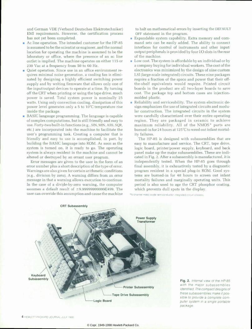
The HP-85 is designed with subassemblies that are easy to manufacture and service. The CRT, tape drive, logic board, printer/power supply, keyboard, and back panel make up the major subassemblies. These are indi cated in Fig. 2. After a subassembly is manufactured, it is independently tested. When the HP-85 goes through final assembly, it is exhaustively tested by a diagnostic program resident in a special plug-in ROM. Good sys tems are burned-in for 48 hours to screen out infant mortality failures and marginally operating units. This period is also used to age the CRT phosphor coating, which prevents dull spots in the display.
*N-channel meta l -ox ide semiconductor in tegra ted-c i rcu i t p rocess
C R T S u b a s s e m b l y
K e y b o a r d S u b a s s e m b l y
P o w e r S u p p l y T r a n s f o r m e r
P r i n t e r S u b a s s e m b l y
T a p e D r i v e S u b a s s e m b l y
L o g i c B o a r d
Fig. 2. In ternal v iew of the HP-85 w i t h t h e m a j o r s u b a s s e m b l i e s ident i f ied. The compact designs of these subassembl ies make i t pos s i b l e t o p rov i de a comp le te com puter sys tem in a s ing le por tab le package.
4 H E W L E T T - P A C K A R D J O U R N A L J U L Y 1 9 8 0
© Copr. 1949-1998 Hewlett-Packard Co.

THIS PROCRftM C«N SOLVE SI TYPES OF CURVE-FIT PROBLEMS. PRESS THE flPPROPRIftTE KEY BELOW TO ENTER DRTfl, OUTPUT flHY RESULTS, OR TO OBTflIN FURTHER INSTRUCTIONS Power Curve Fit Program1 Enter nu»ber of points
PRINT MENU — HELP
OflTfl IN G R O P H
• An internal self-test capability. Should the user suspect a problem with the machine, the user can run a self- contained diagnostic program by pressing the TEST key. This program interrogates all of the machine electronics. If everything checks out, the ASCII character set will be displayed and printed. If a problem is encountered, the message ERROR 23; SELF TEST will appear on the CRT screen. In case of trouble, the customer is advised to seek service from an authorized HP service center or dealer.
Display The display is a 127-mm (5-in) diagonal black-and-white
electromagnetic-deflection CRT. The design of this subas- sembly is discussed in the article on page 19. The memory that holds the display data contains over 65,000 bits and is completely independent of the user's programming mem ory. It is partitioned into alpha and graphics buffers. In alpha mode the display shows 16 lines of 32 characters per line (Fig. 3a). Scrolling keys are provided to view an addi tional 48 lines of alphanumeric data. The graphics display mode is entered by pressing the GRAPH key. Now the dis play provides a resolution of 256 dots wide by 192 dots high. Each dot can be individually accessed by the user with the BPLOT command. In the graphics mode, the SCALE, AXIS, MOVE, DRAW and PLOT commands make it easy to create plots (Fig. 3b) and line drawings. Labels and other alphanumeric information can be added to the graphs, either horizontally or vertically. In addition, HP-85 users can adjust the brightness of the display to adapt to chang ing lighting conditions.
Printer A 32-character-per-line thermal printer (see article, page
22) is provided for hard copy output. A set of 128 ASCII characters is available for printing when outputting al phanumeric copy (e.g., program listings). The printer prints alphanumeric copy bidirectionally at a nominal rate of two lines per second. Short lines are printed faster than long lines.
A COPY key lets the user obtain a copy of the CRT display on thermal paper. If the CRT is in the graphics mode, the printer prints in one direction only and the print output is rotated 90° to allow for strip-chart plotting.
To compensate for variations in paper, printheads, and the type of printing being done, the HP-85 gives the user the ability to lighten or darken the intensity of the output. A
*Amencan Standard Code fo r In fo rmat ion In te rchange
F ig . 3 . (a ) A lphanumer i c d i sp lay m o d e . A f u l l s e t o f 1 2 8 A S C I I characters can be used to provide u p t o 1 6 l i n e s o f 3 2 c h a r a c t e r s e a c h f o r a l p h a n u m e r i c d a t a . Labels to ident i fy selected special key funct ions can be d isp layed at t h e b o t t o m o f t h e d i s p l a y a s s h o w n , ( b ) G r a p h i c s d i s p l a y mode. An a r ray 256 do ts w ide by 192 dots h igh is avai lable for p lot t i n g a n d l a b e l i n g d a t a o n t h e 127-mm CRT.
print intensity switch located under the paper door pro vides for selection of eight levels of print intensity.
Tape Cartr idge Mass storage for the HP-85 is provided by a tape cartridge
system (see article on page 14) using the 98200A data car tridge. Each cartridge holds about 200K bytes of informa tion. This information may be any combination of source program files, binary program files and data files. The direc tory stored on the tape will hold 42 six-character file names. By using the CATalog command, the user can easily review the contents of any data cartridge. A portion (256 bytes) of the directory is automatically stored in the system RAM. This significantly reduces the time required to access a file.
The HP-85 tape electronics can drive the tape at two different speeds. When searching for a file the tape speed is 1524 mm/s (60 in/s). Once the file is found, the speed for read/write is slowed to 254 mm/s (10 in/s). This corresponds to a data transfer rate of 650 bytes per second.
An autostart capability is provided by the system firmware. When power is applied to the HP-85, it automati cally rewinds the tape and reads the tape directory, looking for a program named Autost. If the file exists, the computer will find it on the tape, load it into memory, and im mediately start running the program. Autost programs are supplied with some HP software pacs or can be generated by users for their particular needs.
Security is available for the files stored on the tape cart ridge. When storing a file the user can specify one of four types be security for that file. Also, the entire cartridge can be manually protected against inadvertent overwriting by set ting the write-protect switch that exists on each cartridge.
Keyboard The keyboard is partitioned into four sections as shown
in Fig. 4. A typewriter keyboard is available for entering alphanumeric data. A numeric pad is provided for fast numeric entries or calculator applications. Directly under the CRT display are four special function keys. Combined with the SHIFT key, these provide eight keys that can inter rupt a running program. The KEY LABEL key causes a de scription (up to eight characters specified by the program mer) of each programmed key to appear on the bottom two lines of the display (Fig. 3a). This serves to remind the user what each key is programmed to do. The top row of keys on the right provides a convenient means to scroll or move the cursor on the display, to operate the printer or tape
JULY 1980 HEWLETT-PACKARD JOURNAL 5
© Copr. 1949-1998 Hewlett-Packard Co.

T y p e w r i t e r K e y b o a r d
unit, or to edit previous input with the INS/RPL and DEL- CHAR keys.
Plug-Ins Four I/O slots are provided in the rear of the unit. An
additional 16K bytes of RAM can be added to the HP-85 by plugging a RAM module into any one of the slots. The programming power of the machine can be enhanced by plugging in a ROM drawer. This drawer can contain from one to six 8K-byte ROM modules. The HP-85 will soon have ROMs available for matrix operations, mass memory inter face, printer and plotter interface and general I/O capability.
Four interface plug-ins have been designed to provide interfacing to four common bus structures. The 82937A HP-IB Interface is currently available for connection and control of devices designed for the IEEE Standard 488-1978 instrumentation bus. An RS-232C serial interface and BCD and GPIO interfaces will also become available soon. For a more extensive discussion of the I/O design and capabilities of the HP-85, refer to the article on page 7.
Enhanced BASIC The HP-85 provides a very powerful BASIC language.
The development and capabilities of this firmware are re viewed in the article on page 26. One feature of the language is its mathematical accuracy. Numbers are carried inter nally in decimal form with 15-digit precision and are rounded to 12 digits for output to the user. They can range in size from 10~499 to 9.99999999999X10499.
The string handling ability of the machine is extensive. A string may be any length, limited only by the amount of available read/write memory.
The CHAIN and COMmon commands allow long pro grams to be segmented and stored separately on the data cartridge. Different segments are brought into memory when needed and executed by the CHAIN statement. COM mon allows current variable values to be passed from one segment to another.
A programmable tone speaker is provided. The user can specify both the frequency and duration of the tone by using the BEEP command. This provides the capability for custom audio error indication, input prompting, or playing Bach.
When debugging a program, the user can take advantage of a number of tools provided by the machine firmware. The user can either single-step through the program operations
Fig . 4 . The HP-85 keyboard is o r g a n i z e d i n t o f o u r s e c t i o n s . B e s i d e s t h e n o r m a l t y p e w r i t e r s e c t ion there is a numer ic keypad for easy entry of data, a group of spe cial funct ion keys located close to t h e C R T d i s p l a y w h e r e t h e i r r e spec t i ve ass igned labe ls may be d i s p l a y e d , a n d a s e t o f c o n t r o l keys f o r f r equen t l y used sys tem c o m m a n d s a n d e d i t i n g / d i s p l a y control.
or run the program. Using the TRACE, TRACE ALL and TRACE VARiable commands, changing variables and changes in the sequence of execution can be viewed. This makes it much easier to find where and why a program does not execute as expected.
In all, there are 42 predefined BASIC functions, 65 BASIC statements and 20 commands available in the standard HP-85 system ROMs. Of the standard 16K bytes of user RAM in the computer, only 10% is reserved for system overhead. The rest is available to the user.
Software To provide the user with solutions for particular prob
lems, additional software packages are available for use by the HP-85. Each machine is sold with a Standard Pac con sisting of a preprogrammed tape cartridge and user's man ual. On this tape there are programs for general mathema tics and business. There is also a game and a music compos ing program. This pac is intended to acquaint the customer with the power of the machine as well as offer solutions to some common problems.
There are other software pacs currently available. A BASIC training pac is intended as a self-teaching course for novice users. Statistics, finance, waveform analysis, mathematics, circuit analysis, games, linear programming and text editing packages are also available.
Todd R. Lynch Todd Lynch is a nat ive o f Rochester , New York. He joined HP Laboratories in 1 972 after working for a year on process contro l log ic designs. Since coming to HP he has worked on compu te r a r ch i tectures, and s ince t ransferr ing to what is now HP's Corval l is Div is ion,
<«. Todd designed the archi tecture for the HP-85 CPU. He was the p ro jec t man ager for the integrated c i rcui ts in the
H P - 8 5 a n d i s n o w p r o j e c t m a n a g e r f o r h igh-end main f rames. He rece ived a BS degree f rom Grove Ci ty Col lege, Pennsylvania in 1970 and an MSEE from the Univers i ty of Wisconsin in
1971. Todd is co-chai rman for the Wi l lamet te Val ley Junior Tennis Tournament and in addi t ion to tennis enjoys woodworking, Softbal l , and sk i ing . He l ives in A lbany, Oregon wi th h is w i fe and new son.
\
6 HEWLETT-PACKARD JOURNAL JULY 1980
© Copr. 1949-1998 Hewlett-Packard Co.

S P E C I F I C A T I O N S H P - 8 5 P e r s o n a l C o m p u t e r
G E N E R A T I O N 5 - 7 0 Â « c
-P N* SPEED T«vo 32-tf·.aiacter fcnes per second C H A R A C T E R S 5 - 7 i o r t i n 7 . 1 0 c e f i GRAPHICS OUTPUT. Dot tor dCT reproouOWn <* CRT <*sp»ay PAPER SIZE 122m <*» It ) tang By 10.8 on (4 3 m| mete roH.
TAPE CARTRIDGE DRIVE P R O G R A M C A P A C I T Y 1 9 5 K b y t e s DATA CAPACITY 210K by las ACCESS Directory, f i te-by-nane. 42 named fites max ERROR RATE i brt »> 10"
; 3 8 2 0 G A S 3 5 - 5 i ?
TONE Programmable forn approunalely 0 ID 4575 Hz DURATION Programmable D E F A U L T T O N E A N D D U R A T I O N = 2 0 0 0 H z . 1 0 0 m s
I O SLOTS NUMBER Four I N T E R F A C E O P T I O N S H P - I B ( 8 2 9 3 7 A ) R S - 2 3 2 G P - I O . B C D . 1 6 K o y l e H A M
module (B2903A). ROM drawer |B2936Ai tor up » Si* ROM modules BASIC LANGUAGE
PREDEFINED FUNCTIONS 42: of which 10 ate tr igonmetnc
S T A T E M E N T S 8 ' 1 6 o * w r i e * a r e t o r g r a p n c s ï 20. 10 ol «her
R E A L - 9 9 9 9 9 9 9 9 9 9 9 9 E 4 9 9 t o - 1 E - 4 9 9 . 0 l E -  « 9  » 9 S H O R T 9 9 9 9 9 E 9 9 1 C - 1 E - 9 9 . à œ . 1 E M T E G E R
» 1041=1 STORAGE -4Q •; -
POWER REQUIREMENTS
WEIGHT 906 kg (20 t o ] VOLTAGE 90-127 Vac fllS V» frne) or 200-254 Vac I230 Vac line» swrtcri
F R E Q U E N C Y 5 0 - 6 0 H z C O N S U M P T I O N 2 5 W
PRICE IN U.S.A. HP-85 base pree. 53 .250 MANUFACTURING DIVISION: CORVALLiS DIVISION
1000 N E CifCieBivtà Córvate . Oregon 97330 USA
Acknowledgments A great deal of credit must be given to the management
team for the HP-85. Ernst Erni was the section manager for the project. His foresight and guidance contributed enor mously to the success of the product. Kent Stockwell was the project manager responsible for the mechanical designs and overall system integrity. Chung Tung's support as lab manager was very beneficial. Tim Williams and John Nairn
served as project managers responsible for the plug-in modules.
Also, credit goes to Marv Higgins, who engineered the subassembly interconnect scheme as well as the EMI shielding design, and to Chuck Dodge, who did the excel lent job of industrial design on the product. Norm Glaeser was responsible for product QA. Déme Clainos and Carmen West contributed their skills in the product marketing area.
Adding I /O Capabi l i ty to the HP-85 With the implementat ion of I /O features, the capabi l i t ies o f a se l f -conta ined persona l computer sys tem are expandab le to cont ro l ins t ruments , add on more power fu l per iphera ls , and even ta lk to o ther computers .
by John H. Nairn, T im I . Mikkelsen, and David J . Sweetser
THE HP-85 is an integrated, stand-alone personal computer. This means that within this single package are contained all of the elements of a small
computer system. Part of Fig. 1 shows a block diagram of the HP-85 mainframe. The box labeled CPU contains the main processor, ROM and RAM memory, operating sys tem, power supply, and all of the other elements that in a large mainframe or minicomputer would constitute the computer itself. The remaining elements provide the human interface, letting a programmer and/or operator communicate with the computer. Besides the obvious advantage of having a complete, functional computer in a single portable unit, the integrated computer architec ture provides certain operational advantages.
For example, in the HP-85, a graphics display created on the CRT can be dumped to the built-in printer by executing a single COPY statement. This feature would be much more difficult if not impossible to provide if the printer were an external device with unknown operational characteristics.
The internal peripherals chosen to be incorporated into the HP-85 make it a complete tool for solving a large variety
of computational problems. However, there are two classes of tasks that require that the system be expandable.
The first class consists of tasks for which the human interface elements need to have more powerful characteris tics than those provided by the internal peripherals. A par ticular application may require a printer capable of full page width printing, or of filling out standard forms in multiple copies. For graphics displays, a full-size plotter with multicolor capability might be required. Or the use of a human interface element not even provided in the basic system, such as a digitizer, may be necessary. The ability to support external as well as internal peripherals greatly ex pands the class of problems the system can solve.
The second class consists of tasks in which it is desirable to eliminate as much of the human interface as possible. In data acquisition applications, measurement instruments are available that can communicate their results directly to the computer, eliminating the need for manual entry of data by an operator. When the computer is capable not only of acquiring and/or performing analyses on the data, but also of making decisions based on that data and providing feed-
J U L Y 1 9 8 0 H E W L E T T - P A C K A R D J O U R N A L ?
© Copr. 1949-1998 Hewlett-Packard Co.

I /O ROM (Plus Other
Add-On ROMs)
Interface Card (or 16K RAM)
Interface Card
Interface Card
HP-85 Ma in f rame
F ig . 1 . The bas i c f unc t i ona l b locks fo r t he HP-85 pe rsona l compute r a re in tegra ted in to a s ing le ma in f rame fo r a se l f - con ta ined compute r sys tem. Four HO s lo ts a re p rov ided to expand system capabi l i ty . Var ious combinat ions (such as the one shown) of the add-on ROM drawer, addi t ional 16K RAM, and per ipheral inter faces can be instal led in these four s lots.
back that modifies the operation of the system to which it is connected, the computer functions as a controller.
Two elements are required to add I/O capability to the HP-85. First, a piece of firmware (I/O ROM) is required to give the operator access to the interfaced device. Second, a piece of hardware (interface card) is required to provide electrical, mechanical, and timing compatibility for the de vice to be interfaced to the computer.
The HP-85 is a BASIC language computer. Many of the language features are similar or identical in syntax and semantics to the interfacing statements on the 9835 and 9845 Computers.1'2 The design of the HP-85 interfacing capability also draws heavily from the 9825 Computer's I/O architecture.3
The HP-85 contains both read-only memory (ROM) and read-write or random-access memory (RAM). The RAM contains the user's BASIC language program (software) and data. The ROM contains the machine language program (firmware) which recognizes and executes the statements provided by the BASIC language. Thus, the operating sys tem ROM in the HP-85 provides such statements as PRINT, DISP, and INPUT for accessing the internal peripherals.
When external peripherals are added, their wider range of capabilities requires more extensive BASIC language statements to fully use these capabilities. Additional plug- in modules, called add-on ROMs, merely enrich the BASIC language by increasing the number of statements and func tions that can be recognized and executed.
Some of these add-on ROMs may be dedicated to a par ticular device. For example, a ROM may add statements to the BASIC language which are designed only to provide complete control of a floppy disc or of a full-size plotter. The I/O ROM, on the other hand, is designed to be as much as possible a general-purpose tool for communicating with the wide variety of peripherals and instruments available.
Almost all computers provide language extensions for outputting data to a device or entering data from a device. The OUTPUT and ENTER statements are usually sufficient for communicating with external peripherals. In controller applications, however, where timing may be critical and the speed of the external devices and instruments may not be well matched to the speed of the computer, other methods of transferring data and control information can increase the performance of the system. In many cases this can make the difference in whether the application can be done at all. For example, in taking data from very slow devices, the ability to transfer data under interrupt allows the HP-85 to perform other operations instead of waiting on the slow device, thus increasing system throughput. In the other extreme, being able to capture data in a burst transfer from a very fast device and then process the data into inter nal format at a later time can be a "make-or-break" capabil ity in fast data acquisition applications.
In the back of the HP-85 are four slots that allow add-on ROMs, add-on RAM, and interface cards to be connected to the internal memory bus. A single ROM drawer containing the I/O ROM and up to five other add-on ROMs can be plugged into any one of these slots. Thus a typical interfac ing configuration can include the ROM drawer and three interface cards; or the ROM drawer, the add-on RAM mod ule and two interface cards, as shown in Fig. 1.
On each interface card is a custom integrated circuit called the translator chip (TC), which translates between the timing and protocol requirements of the internal mem ory bus and a microcomputer bus (Fig. 2). Each card also contains an 8049 microcomputer and a set of discrete driv ers that implement the electrical and protocol requirements
Bid i rec t i ona l T r a n s c e i v e r s
I S C 2 I S C 1 I S S e l e c t O Q Q C o d e V V V
S w i t c h e s p
82937A HP- IB In te r face
F ig . 2 . Typ i ca l i n te r face ca rd de s ign . The t rans la to r ch ip permi ts c o m m u n i c a t i o n b e t w e e n t h e s y s tem CPU and the mic roprocessor o n b o a r d t h e i n t e r f a c e . T h e I / O p r o c e s s o r t h e n i m p l e m e n t s t h e electr ical requirements for the par t icular interface funct ions.
8 H E W L E T T - P A C K A R D J O U R N A L J U L Y 1 9 8 0
© Copr. 1949-1998 Hewlett-Packard Co.
for that card. The most general-purpose interface card is the sixteen-bit
parallel card (GPIO). Sixteen TTL compatible bidirectional lines and sixteen open-collector output lines, plus a variety of status, control, and handshake lines make this card a versatile workhorse. A variation of this card, with the input lines organized into four-bit nibbles, is also available for interfacing devices that operate in binary-coded-decimal (BCD) format.
A third type of interface card is designed to connect the HP-85 to serial I/O devices using either RS-232C or 20-mA current loop configurations. This card will also allow ter minals to be connected to the HP-85, or allow the HP-85 to be connected to a modem or a host computer.
The fourth card is the 82937A HP-IB Interface, the HP- 85's implementation of IEEE Standard 488-1978. Because of the microprocessor included on this card, a very powerful implementation of both controller and noncontroller capabilities is provided.
The HP-IB Interface Card is available now and the others (GPIO, BCD, and Serial I/O) will be available later.
I /O ROM There are three areas that any interfacing capability in a
computing system must connect — the programmer, the operating system, and the I/O hardware. On HP's interpre tive computers the user interface is through keyword execu tion of the language extensions provided by the I/O ROM. An important aspect of the friendliness of these computers is the choice between calculator and program mode execu tion of the keywords. The program mode means the state ment has a line number and is to be stored for later program execution (parsed, stored in the program memory, exe cuted at RUN time). The calculator mode means the state ment does not have a line number and is to be immediately executed (parsed, stored in temporary memory, and exe cuted).
In the HP-85, the I/O hardware — the interface card — is a type of channel processor. A channel processor is a computer with limited resources that performs many of the central computer's interfacing tasks. The interface to the I/O hardware is the I/O drivers. These implement the protocol that the central computer uses to tell the I/O card what it is supposed to be doing. The I/O drivers include data passage routines, command passage routines, status and control routines, and an interrupt handler.
The interface to the operating system is what makes inter facing capabilities a natural extension of the computing system. For example, I/O events can cause changes in the BASIC program flow. The interface to the operating system is achieved primarily in three ways — routine linkages, read/write memory use, and register use. An example of a routine linkage is the print driver — when the programmer specifies PRINTER IS 4, all PRINT commands cause a routine in read/write memory to be called. When the I/O ROM is in the system it replaces this read/write memory routine with a routine of its own to handle the PRINT. If the I/O ROM is not in the system the default system routine generates an error.
Read/write memory is used when the I/O ROM passes
•Parsing is the operation of taking a statement l ine and decomposing it into its elementary parts
information to or from a system-defined location. For example, when an error occurs in an I O ROM statement, the I O ROM puts the error number in a common location that the system knows.
The register interface to the operating system consists of some CPU registers that the system reserves for system status and control. For example, register sixteen indicates the machine state — idle, running, and so forth.
There are several basic groups of interfacing and related capabilities provided by the HP-85 I/O ROM to the user. • Formatted transfers — input and output of data with for
matting and conversions • Buffered transfers — fast handshake and interrupt data
transfers through explicit buffering • Register access — ability to set and interrogate the card
configuration • Interrupt access — ability to receive hardware interrupts • Timeouts — ability to detect an inoperative card or
peripheral • Miscellaneous — keyboard masking, base conversion and
binary operations • HP-IB control — high-level access to HP-IB capabilities.
The ability to input and output data (formatted transfers) is probably the most commonly used of all interfacing capabilities. In some systems input and output are the only interface functions provided. The HP-85 allows for free- field or formatted input (via ENTER) and output (via OUT PUT). These statements are the tools that a programmer uses to get arbitrary string and numeric data into and out of the computer. Many times the peripheral has a non-ASCII character set, so a character conversion capability is pro vided to allow the programmer to set up a conversion table and deal with data as if it were normal ASCII data.
OUTPUT and ENTER are medium-performance data trans fer mechanisms that consume the machine (program execu tion stops until the current statement is completed). Buf fered transfers provide two additional methods to get data into and out of the HP-85 — interrupt and fast handshake. The interrupt mode of data transfer is lower in performance than ENTER and OUTPUT, but does not tie up the comput er, because it can be doing many other things in addition to the interrupt transfer. For example, while transferring data in the interrupt mode, the HP-85 can plot to the CRT, do arithmetic computation, print to the internal printer, or transfer data through other interrupt transfers. The fast handshake mode is much better in performance than ENTER and OUTPUT, but still ties up the computer. Neither of these buffered transfer modes performs any formatting. The data is placed into or taken out of an I/O buffer — hence the name "buffered" transfers. The buffer is a string variable that has been modified for use by the I/O ROM (via IOBUF- FER). The buffered transfers are performed via the TRANS FER statement.
The programmer needs to access specific attributes of each interface card (register access). These attributes vary from card to card. For example, an RS-232 user would like to get at the clear-to-send bit and change its state; a sixteen- bit parallel interface user would like to change the logic sense from positive-true to negative-true logic. These fea tures would become cumbersome if all of them were pro vided at the BASIC language level. Hundreds of keywords
JULY 1 980 HEWLETT-PACKARD JOURNAL 9
© Copr. 1949-1998 Hewlett-Packard Co.

would be required. Instead, there can be up to sixteen card status registers and twenty-four card control registers on any interface card (accessed via STATUS and CONTROL). These registers allow the programmer access to the various low-level capabilities of the interface: parity, end-of- transmission character sequences, interface control and data lines, error indicators, and so on.
A programmer often needs to perform some operation when an interface condition occurs (interrupt access). Rather than constantly checking for these conditions, the interface card can check for the programmer (via ENABLE INTR), and when the condition happens, the end-of-line branch is taken to a BASIC service routine. The location of the service routine is set up with the ON INTR statement.
The timeout capability lets a programmer set an arbitrary length of time (from 1 to 32767 milliseconds) to wait for a response from the I/O hardware. Once a timeout has oc curred, there is an end-of-line branch taken to a BASIC service
routine specified by the programmer. The miscellaneous statements and functions do not per
form any interfacing capabilities. They are included to make the job of the interface programmer easier. There is the capability to mask out sections of the keyboard so that the operator does not inadvertently disrupt program flow. Base conversions for decimal numbers to and from binary, octal, and hexadecimal allow the programmer to display interfacing information in a convenient form. Boolean func tions (and, or, exclusive or, complement, bit test) let the programmer test and modify interfacing information easily.
HP-IB is a mnemonic for Hewlett-Packard's implementa tion of IEEE Standard 488-1978. Since HP-IB is such a pervasive interfacing standard for instrumentation, print ers, plotters and peripherals of all descriptions, there are several high-level HP-IB control statements in the HP-85 I/O ROM. There are many commands that send multiline mes sages on the HP-IB (such as TRIGGER, PASS CONTROL,
S C 2 S C 1 S C O + 6 V + 5 V -o — o
Data Bus
(8 b i ts )
H«J L^H
Write SR Write IB
Read CR Read OB
Fig. timing requirements diagram of the translator chip that translates timing and protocol requirements be tween the HP-85 CPU and the in te r face card I /O processor .
1 0 H E W L E T T - P A C K A R D J O U R N A L J U L Y 1 9 8 0
© Copr. 1949-1998 Hewlett-Packard Co.

CLEAR, etc.). Multiline messages are those commands that the controller handshakes to the various devices on the bus in bit-parallel, byte-serial fashion. There are also com mands that send uni-line messages on the HP-IB (such as ABORTIO. LOCAL. REQUEST, etc.), and there are functions that return status information (PPOLL and SPOLL) . The other cards (Serial I/O, GPIO, BCD) use some of these state ments for their own functions when appropriate.
Design of the 82937A HP- IB Inter face To implement all the capabilities planned for the I/O
ROM, it was necessary to design intelligent I/O cards. Each I/O card contains a single-chip microcomputer to (1) com municate with the HP-85 CPU and (2) control and respond to the signals on the interface. The result of this is highly significant — the I/O ROM is not required to know what type of interface is being accessed. Communication between the I/O ROM and an I/O card is totally independent of the type of card; it is the card's responsibility to perform the appro priate I/O function over the interface.
This enhanced capability of the I/O cards permits more capability to be put in the I/O ROM than would have other wise been possible. Also, this design approach permits overlapped processing; that is, the HP-85 CPU can be run ning a BASIC program while an interface card is performing I/O operations. An excellent example of this design concept is the HP-85 interface to the HP-IB. The principal elements of the HP-IB card are shown in Fig. 3. They are: 1. Translator chip: The translator chip interfaces between the HP-85 CPU and the I/O processor on the card. It provides electrical and timing compatibility between the buses and contains several registers to implement the communica tions protocol between the CPU and the I/O processor. 2. I/O processor: The I/O processor is a single-chip mi crocomputer containing 2048 bytes of program ROM and 128 bytes of RAM. It performs two tasks: it communicates with the CPU through the translator chip to determine what I/O operation is desired, and it implements the I/O operation over the bus using the bus transceivers. 3. Bus transceivers and control logic: Bidirectional trans ceivers are used by the I/O processor to control and to respond to signals on the bus. A latch, written to by the I/O processor, controls the direction of the transceivers and also controls I/O processor interrupts.
The translator chip (Fig. 3), hereafter called the TC, was designed to achieve several goals: • Support eight peripheral select codes • Let the HP-85 processor interrupt the I/O processor • Let the I/O processor interrupt the HP-85 CPU • Let the HP-85 CPU do a hardware reset of the I/O proces
sor • Provide a means for the I/O processor to halt the HP-85
CPU • Provide general-purpose data registers for bidirectional
communications between the two processors. I/O for the HP-85 is memory-mapped. To support eight
select codes, the TC's address is switch-settable to one of eight different addresses. Three switches reside in the I/O card. In the process of setting the card's select code, the user is actually setting the card's address. A mapping is done in the I/O ROM to translate from the select code specified in
the program to the appropriate address. Each TC actually occupies a pair of addresses. The lower
address is used to access the control register (write-only by the HP-85 CPU and read-only by the I'O processor) and the status register (read-only by the HP-85 CPU and write-only by the I O processor). The upper address of the pair accesses the output buffer (write-only by the HP-85 CPU and read only by the I/O processor) and the input buffer (read-only by the HP-85 CPU and write-only by the I/O processor).
The input and output buffers are used for general- purpose communications between the two processors. Bits in the in and status registers are used to qualify data in these buffers as well as report the status of various events. To synchronize the flow of data, each processor can ascer tain the condition of these buffers via flags in the status and control registers. These flags are DBF (output buffer full) and IBF (input buffer full). OBF is set when the HP-85 CPU writes to the output buffer and is cleared when the I/O processor reads the output buffer. Similarly, IBF is set when the I/O processor writes to the input buffer and is cleared when the CPU reads the input buffer.
The I/O processor and HP-85 CPU exist in a master-slave relationship, with the CPU being the master. The CPU sends instructions and data to the I/O processor via the output buffer. The software protocol between the CPU and the I/O processor defines a bit in the control register as COM, for command. COM is set high by the CPU before writing a command into the output buffer; COM is set low by the CPU before writing data into the output buffer. While the I/O processor is acting on the data or command, it sets a bit in the status register to 1, which is defined as the BUSY bit. When the I/O processor finishes acting upon the command or data byte in the output buffer, it sets BUSY low, which tells the CPU that it is done.
Several commands received from the CPU require that
E n t r y
N o ^ ^ ^ j
, U
F i g . 4 . I d l e l o o p f o r t h e 8 2 9 3 7 A H P - I B I n t e r f a c e c a r d I / O p r o c e s s o r . T h i s l o o p c a n b e e x i t e d a t a n y p o i n t u p o n a n in terrupt f rom the CPU or in ter face bus.
JULY 1980 HEWLETT-PACKARD JOURNAL 11
© Copr. 1949-1998 Hewlett-Packard Co.

the I/O processor return data to the CPU (e.g., the command generated by the CPU to execute the user's STATUS state ment) . The I/O processor returns the data in the input buffer. The CPU monitors IBFto determine when the data is written to the input buffer, while the I/O processor monitors IBF to determine when the data has been read by the CPU.
Associated with each I/O ROM statement that accesses I/O is a set of rules that define the communications protocol between the HP-85 CPU and the I/O processor. The com munications protocol not only defines the interaction dis cussed above, but also covers the interrupt protocol whereby each processor may interrupt the other.
The HP-85 CPU communicates with the I/O processor primarily to convey bus control commands to the I/O pro cessor. The I/O processor then controls the bus as dictated by the CPU and within the bounds specified by IEEE Stan dard 488-1978. At power-on, the I/O processor reads the five address switches and the system controller switch located on the interface card. These switches are set by the user to configure the I/O processor's HP-IB address and to desig nate whether or not the I/O processor is to assume the role of system controller at power-on. The user can verify the switch settings by reading the STATUS register.
Fig. 4 shows the idle loop executed by the I/O processor, demonstrating its interaction with the CPU and the bus. In its idle loop, the I/O processor monitors OBF to see if the CPU has written any new information into it; if so, the I/O processor sets BUSY = 1, reads the output buffer and pro cesses it as a command (COM = 1) or data (COM = 0).
If the I/O processor is the active controller of the HP-IB , it polls SRQ. If SRQ is true and the user has enabled an end-of- line interrupt branch on SRQ, then the SRQ end-of-line in terrupt bit is set. The I/O processor subsequently examines all eight interrupt cause bits; if any are set, the I/O processor interrupts the CPU. While the SRQ interrupt cause bit is set as the of of polling, the other bits are set as the result of interrupts from the bus as discussed below.
Interrupts of the I/O processor originate from two sources— the CPU (via the TC), and the bus. The CPU inter rupts for certain operations, such as STATUS, to guarantee timely operation regardless of the state of the I/O processor. For example, if the I/O processor is busy handshaking data
on the bus to a device that is taking an indefinite length of time, then an interrupting STATUS operation guarantees an immediate return of data.
Certain HP-IB signals mandate a response within a time limit. For example, IFC (interface clear) must be responded to within 100 microseconds. To guarantee this, IFC can be enabled to interrupt the I/O processor. Likewise, REN (re mote enable) must also be responded to within 100 mi croseconds, and thus can be used to interrupt the I/O pro cessor. ATN (attention) imposes no timing requirements on the I/O processor but is used as an interrupt input to ensure that ongoing I/O is properly suspended. During an IFC or ATN interrupt, end-of-line interrupt bits may be set, de pending upon the interrupt enable mask provided by the user. The interrupt enable bits are examined back in the idle loop; if any are set, the I/O processor interrupts the CPU. The CPU then typically executes the branch specified in the user's BASIC program.
Interface Select Codes and Device Speci f iers The HP-85 can have up to three interface cards plugged
into it (see Fig. 5). It also has the internal CRT and printer that I/O ROM users may want to access. How does a pro grammer tell the I/O ROM which of these devices to inter face with? This is done through interface seJect codes.
Every I/O ROM statement that deals with an interface specifies as part of the statement the interface select code. The range of select codes is as follows:
1 : INTERNAL CRT 2 : INTERNAL PRINTER 3 : EXTERNAL I /O
10 : EXTERNAL I /O
Select codes 1 and 2 are accessible only through OUTPUT. An example of interface select codes is:
10 OUTPUT 1; "This line goes to the CRT" 20 OUTPUT 2; "This line goes to the printer" 30 OUTPUT 7; "This line goes to an external
device"
Fig. 5 . Typ ica l HP-85 in ter face in s t a l l a t i o n . T h e a d d - o n R O M drawer and the 82937 A HP- IB In t e r f a c e a r e s h o w n . T h e u n u s e d slots can be used to add two other interfaces or another interface and the 16K RAM module .
1 2 H E W L E T T - P A C K A R D J O U R N A L J U L Y 1 9 8 0
© Copr. 1949-1998 Hewlett-Packard Co.

Using HP-85 I/O Capabilities
The HP-85 I O ROM al lows for extreme ease of use. The fol lowing examples show a wide range of capabi l i t ies of the HP-85 in a simple inter facing appl icat ion.
Let 's assume that you, the user , have an HP-85. an I /O ROM. an HP- IB card, and a 3437A system vo l tmeter . Let 's a lso assume that these components a re hooked toge ther , powered up , and work ing properly.
You wou ld l i ke to ge t a read ing f rom the vo l tmeter . The 3437A's dev ice address i s 24 (as sh ipped f rom the fac to ry ) and the HP- IB in ter face card is se lect code 7 (as shipped f rom the factory) . There fore the address that you should be us ing is 724. You want to get a reading from the 3437A. To do that you have to execute the fol lowing statement:
E N T E R 7 2 4 . A
After you have executed this statement, the var iable A wi l l contain the reading f rom the vol tmeter . That is a l l there is to do.
A program to get one read ing and d isp lay i t , wou ld be l i ke th is : 2 0 E N T E R 7 2 4 : A
3 0 D I S P A
5 0 E N D
Now suppose you want to take in a hundred readings and display them this: the internal HP-85 CRT. The fol lowing program wil l do this:
10 FOR 1=1 TO 100 2 0 E N T E R 7 2 4 A
3 0 D I S P A
4 0 N E X T
5 0 E N D
Now suppose you want to p lo t these 100 readings. The fo l lowing program does th is :
1 S C A L E 1 , 1 0 0 . - 2 0 . 2 0
2 G R A P H
3 G C L E A R
4 M O V E 1 , 0
1 0 F O R 1 = 1 T O 1 0 0
2 0 E N T E R 7 2 4 . A
3 0 P L O T I , A
4 0 N E X T I
5 0 E N D
Now, less that this is not fast enough. Your application requires less t ime the vo l tmete r read ings . F i rs t o f a l l , you know tha t the 3437A i s capab le o f much be t te r pe r fo rmance . To ge t t he HP-85 to take readings at a faster rate will require a type of data exchange known as a buffered transfer. This means that you tell the HP-85 to take the data into data buffer as fast as it can and then at a later time take the data out of the bu f fe r and tu rn i t in to numer ic da ta tha t the computer can use computat iona l ly . The fo l lowing program does th is fas t t ransfer and plots the data as before.
1 S C A L E 1 , 1 0 0 . - 2 0 , 2 0
2 G R A P H
3 G C L E A R
4 M O V E 1 , 0
5 D I M B $ [ 7 0 9 ]
6 I O B U F F E R B $
7 O U T P U T 7 2 4 . " N 1 0 0 S
8 ' T H E P R E V I O U S L I N E C O N F I G U R E S T H E V O L T M E T E R
9 T R A N S F E R 7 2 4 T O B $ F H S : C O U N T 7 0 1
1 0 F O R 1 = 1 T O 1 0 0
2 0 E N T E R B Ã U S I N G " # . K , A
3 0 P L O T L A
4 0 N E X T I
5 0 E N D
-Tim Mikkelsen
The select code of an I/O card is set by switches mounted on the card. These switches are preset at the factory, depend ing on the type of the interface (e.g.. HP-IB's select code is preset to 7). An example where the programmer might want to change the select code would be when there are two HP-IB interfaces in one HP-85. The programmer might do this to extend the number of HP-IB devices on one comput er, or if the computer is to be a controller on one HP-IB and just another device on the other. In such a case, the pro grammer would have to change one of the select codes to prevent a hardware conflict.
This, however, is not enough. The HP-IB standard allows for up to 31 device addresses on a single interface (14 is the physical limit that any HP-IB interface can support). The 16-bit general-purpose interface allows the programmer ac cess to four eight-bit ports in various ways (using a total of sixteen logical addresses). The BCD interface allows for one or two channels of information consisting of data fields, function codes, and error indications which are accessible in various combinations (using a total of seven logical ad dresses). How does the programmer tell the I/O ROM which device address to talk to? This is done through device specifiers.
Tim I . Mikkelsen Tim Mikkelsen came to HP in 1 977 after comple t ing BS and MS degrees in computer science at Iowa State Univer s i ty in 1975 and 1977, respect ive ly . Cur ren t l y a p roduc t marke t ing en gineer, he has worked on I/O ROMs for the HP-85 and the 9835 and 9845 Computers. From Missouri Valley, Iowa, Tim is a member of IEEE, and now lives in Fort Col l ins, Colorado. He is marr ied wi th one daughter . When not invo lved wi th woodwork ing, downhi l l sk i ing, per sona l comput ing , and photography , Tim is busy trying to restore a 1 964 TR4 sportscar.
John H. Nairn I Born in Pit tsburgh, Kansas, John Nairn
went to school in Denver , Colorado, | earning a BS in chemistry at Regis Col- | lege in 1967. He then received the MS
and PhD degrees in mathemat ica l physics f rom Rice Universi ty, Houston, Texas in 1971. Af ter work ing as a reg ional analyst John jo ined HP in 1972 and has had var ious responsib i l i t ies
s i n c e t h e n . I n i t i a l l y h e w o r k e d i n m a r k e t - ^ I i n g o n t h e 9 8 2 1 a n d 9 8 3 0 C a l c u l a t o r s
f a n d t h e n d i d R & D w o r k f o r t h e 9 8 2 5 I / O . In 1976, John returned to market ing as in ter fac ing product manager . Later , in 1978, he moved to his current posi t ion
as R&D project manager for the HP-85 I/O. John is a member of ACM, a co-inventor for a patent related to the 9825 Calculator, and author of a regular ser ies of ar t ic les for HP's Keyboard magazine. He l ives in For t Col l ins, Colorado and is in terested in photography, h ik ing, recreat ional mathemat ics and fo lk gui tar .
J U L Y 1 9 8 0 H E W L E T T - P A C K A R D J O U R N A L 1 3
© Copr. 1949-1998 Hewlett-Packard Co.

David J . Sweetser Born in Woodland, Cal i forn ia , Dave Swee tse r a t t ended Harvey Mudd Co l lege , where he earned BS and MS de grees in engineering in 1971 and 1972, respect ive ly . Af ter f ive years wi th an aerospace company, Dave joined HP in 1977 and has designed an interface for the HP-85 in addi t ion to wr i t ing I /O sof tware. He and h is wi fe , who is an engineer a t HP's Loveland Inst rument Div is ion, des igned the i r own house, which is presently being built on 3 acres of land between Loveland and Fort Col l ins, Colorado. Dave enjoys raf t ing, b icyc l ing , backpack ing , c ross-count ry sk i ing and snow camping .
The device specifier is like an interface select code, ex cept that it includes both the select code and the device address. Notice that the range of device addresses is from 00 to 31. To build a device specifier — multiply the select code by 100 and add the device address. Hence select code 7, device 24 would be 7x100 + 24 = 724. Device addresses are generally preset by the factory, but can be changed in a manner similar to changing the interface select code.
References 1. S.L. Chumbley, "Extending Possibilities in Desktop Comput ing," Hewlett-Packard Journal, May 1979. 2. W.D. Eads and J.M. Walden, "A Highly Integrated Desktop Computer System," Hewlett-Packard Journal, April 1978. 3. D.E. Morris, CJ. Christopher, G.W. Chance, and D.B. Barney, "Third Generation Programmable Calculator Has Computer-Like Capabilities," Hewlett-Packard Journal, June 1976.
A Compact Tape Transport Subassembly Designed for Reliability and Low Cost by Douglas J . Col l ins and Br ian G. Spreadbury
OVER THE LAST FOUR YEARS Hewlett-Packard has developed a series of magnetic transports1 '2>3 for the 98200A data cartridge shown in Fig. 1.
The use of this small data cartridge was selected because of proven reliability, large data capacity, ease of use, and low system cost.
The tape system integral to the HP-85 is in many ways a refinement of previous designs. However, the total integra tion of the transport with a single printed circuit board into one small package called for new techniques in electrical and mechanical design.
Transport E lectronics Design To incorporate a tape system into the compact HP-85
package required the cartridge transport to be small and to consume a minimum of power. Unfortunately, a relatively powerful motor is needed to drive the tape. For best effi ciency, a pulse-width-modulated 20-kHz signal controls the motor drive transistors to keep them either cut off or fully saturated (turned on). These large power pulses can generate severe noise levels on the ten-millivolt signal lines from the tape head. To prevent this, the entire read/write circuitry is located within three centimetres of the magnetic head. Also, the motor drive circuitry has a separate power supply and is independently grounded.
The heart of the tape system electronics is the custom
NMOS tape controller 1C. It performs the tasks of interfacing to the HP-85 CPU, controlling motor speed and direction, and encoding/decoding data for the tape. Two Schmitt- trigger inputs provide direct sensing of the analog signals
Fig. 1. The 98200 A mini data cart r idge is a compact storage medium for data and programs, and has proven rel iabi l i ty and flexibility.
1 4 H E W L E T T - P A C K A R D J O U R N A L J U L Y '
© Copr. 1949-1998 Hewlett-Packard Co.

Fig . 2 . F low d iagram for a t rad i t iona l speed cont ro l des ign.
from of phototransistors that are used for optical sensing of the end-of-tape hole and the motor tachometer disc. Despite all of the functions included on this 1C chip, it remains remarkably small (approximately 14 square millimetres in area) and typically dissipates about fifty milliwatts of power.
To keep the size of this 1C small, the simple calculations required for tape operation are delegated to the HP-85 cen tral processor. Functions such as gap length measurement, checksum generation, and end-of-tape detection are per formed by the CPU. These computations are trivial for the CPU, but would require the addition of multibyte adders and counters to the tape controller 1C if it were required to do such functions.
Digital Servo Design To help understand the digital servo system used here,
consider the tradit ional posit ion control system shown in Fig. 2. For this case, the cumulative error &>e is held to zero by integration, thereby providing no long-term speed error. The system is given stability by feed-forward com pensation Kj. To transform this system into a digital sys tem, the integrator and its associated summing junction are replaced by an up/down counter Cl and a binary adder as shown in Fig. 3.
An optical tachometer generates a series of pulses that are fed into down counter C2. On each tachometer pulse the counter is loaded with the desired reference period (the reciprocal of the desired tachometer frequency). Counter C2 counts down until the next tachometer pulse is detected and then its output is evaluated. If the sign of the output is
negative, the time between successive tachometer pulses is too long, indicating a low motor speed. This causes Cl to count up. which generates a longer duty cycle for the motor drive pulse-width output. If the output of C2 is positive, Cl counts down and the motor slows down. The value of the C2 output i s scaled and fed forward through the adder to stabilize the system. Since the servo output is recalculated for each tachometer pulse, the overall gain of the system varies with the speed of the motor. However, if the servo is operating properly, the speed variation will be small and the gain modulation will be negligible.
There are only two speeds required for the HP-85 tape system — 254 and 1524 mm s (10 and 60 in/s). To change the speed, the reference period is modified and scaling adjust ments are made to the servo timing to compensate for the change in gain.
The servo is run open-loop to start or stop the motor. The acceleration or deceleration is controlled by incrementing or decrementing Cl and feeding its output directly to the pulse-width modula tor . No addi t ional counters are re quired.
The digital pulse-width modulator directly interfaces to four Darlington-transistor motor drivers. To protect the motor and drivers during high load condit ions, a table lookup ROM is used to solve the defining equation for a direct-current, permanent-magnet motor.
V = Raxla Kexo>a
where V is the voltage applied to the motor (proportional to duty cycle), Ra is the armature resistance, Ia is the arma ture current, Ke is the back EMF constant, and ¡na is the motor's angular velocity.
Given the maximum armature current and motor con stants Ra and Ke, the ROM is programmed to solve for the maximum duty cycle allowed to drive the motor. The out put of C2 in Fig. 3 is used as the input to this ROM because its reciprocal is proportional to the motor's angular veloc ity. For each tachometer pulse, the maximum allowable duty cycle is calculated and compared to the servo output. The lesser of the two values is output to the motor drive circuitry. A delay is added between the time of excessive load detection and the time the armature current is actually
Motor Drivers
F i g . 3 . B l o c k d i a g r a m o f d i g i t a l se r vo e l ec t r on i cs f o r mon i t o r i ng a n d c o n t r o l l i n g t h e t a p e d r i v e motor speed.
JULY 1980 HEWLETT-PACKARD JOURNAL 15
© Copr. 1949-1998 Hewlett-Packard Co.
limited to prevent short-term speed perturbations from af fecting the motor speed. This eliminates the need for a current-sense resistor and associated detection circuitry that would sacrifice motor efficiency.
Additionally, the motor is protected against a stall condi tion by shutting the motor down if the tachometer fre quency becomes excessively low. Both the stall and current-limit conditions are reflected in the tape control ler's status, which is monitored by the HP-85 system firmware.
Data Coding Information is transferred to and from the tape controller
1C on a byte-by-byte basis. Data written onto the tape is first precompensated (lengthened or shortened, dependent on the value of adjacent bits) to prevent magnetic pulse crowd ing on the tape. A delta-distance code with a ratio of 1.75:1 is used.4 That is, the distance between magnetic flux rever sals on the tape determines the value of the bit, with the distance for a one being 1.75 times greater than that for a zero.
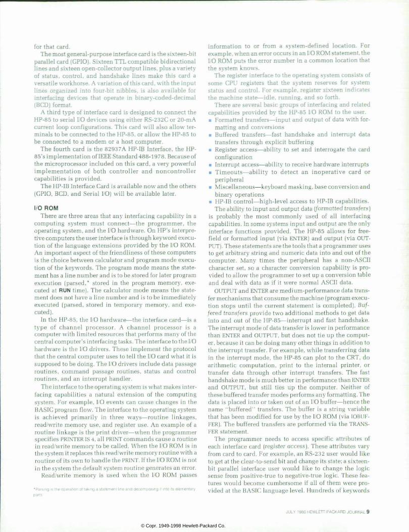
The decoder diagrammed in Fig. 4 is a speed tolerant design that compares the current bit pulse width with a continually updated nominal pulse width contained in the up/down counter. The down counter is essentially used as a variable modulus counter set by the contents of the up/ down counter. At each magnetic flux reversal, the down counter is loaded with the nominal period for a zero bit. When this quantity is counted down to zero, the state counter is incremented and the down counter is reloaded. With the decoder in state one now, one-fourth of the nomi nal zero-bit period is counted down and the down counter is reloaded again. The next decoder state counts down one half of the nominal zero-bit period. The value of the pulse being decoded is determined by the current state of the decoder when the next flux reversal occurs. State zero indi-
Data Output
Fig. the Logic diagram for the decoder circuit that converts the t ime in tervals between successive f lux reversals on the tape into the equivalent b inary data.
Carry Out
F i g . 5 . T h e d y n a m i c a l l y c l o c k e d l o g i c d e s i g n f o r c o u n t e r s tages wh ich ach ieve op t imum speed fo r m in imum 1C ch ip area.
cates a shorter-than-nominal zero-bit period and so decre ments the current count for the nominal period. State one is for a long zero-bit period and increments the nominal count. States two and three correspond to short and long one-bit periods, respectively. The transition from state two to state three happens after the last flux reversal at exactly 1.75 times the nominal zero-bit period. In this manner, the 1.75:1 delta-distance code can be decoded with a minimum of logic circuitry.
Logic Design To implement all this with a custom NMOS LSI circuit
design, the various circuits must be optimized for the re quired speed with the lowest number of transistors. Gate level minimization does not apply here. However, the number of gate delays for any circuit path should not be too many, otherwise chip area and power will be wasted.
The counters in the tape controller 1C are implemented using an alternating positive/negative logic scheme that is dynamically clocked as drawn in Fig. 5. The sense of the carry is inverted for each bit into the counter. This counter has one gate delay per stage (from the carry), which is optimum for the number of stages required.
Data is stored by the NMOS capacitances in the counter and is refreshed by two nonoverlapping clocks. The use of two clocks prevents possible race conditions.
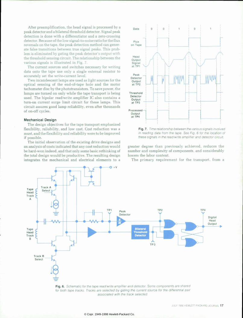
Read/Write Ampli f ier A single bipolar read/write amplifier 1C transforms coded
digital information from the tape controller 1C into magne tic pulses on the tape, and back again. The basic read circuit is diagrammed in Fig. 6. The configuration of the two magnetic-head read coils permits the use of shared input and feedback components for both tape tracks, thus reduc ing the number of external parts needed. Each track has its own differential transistor pair, but shares a common volt age amplifier. Track selection is accomplished by gating the respective current source for the desired input pair.
1 6 H E W L E T T - P A C K A R D J O U R N A L J U L Y 1 9 8 0
© Copr. 1949-1998 Hewlett-Packard Co.
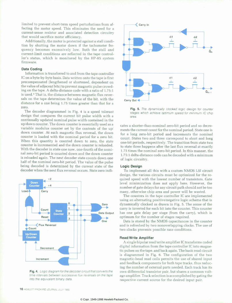
After preamplification, the head signal is processed by a peak detector and a bilateral threshold detector. Signal peak detection is done with a differentiator and a zero-crossing detector. Because of the low signal-to-noise ratio for the flux reversals on the tape, the peak detection method can gener ate false transitions between true signal peaks. This prob lem is eliminated by gating the peak detector's output with the threshold sensing circuit. The relationship between the various signals is illustrated in Fig. 7.
The current sources and switches necessary for writing data onto the tape use only a single external resistor to accurately set the write-current level.
Two incandescent lamps are used as light sources for the optical sensing of the end-of-tape hole and the motor tachometer disc by the phototransistors. To save power, the lamps are turned on only while the tape transport is being used. The bipolar read/write amplifier 1C also contains a turn-on current surge limit circuit for these lamps. This circuit assures good lamp reliability, even after thousands of on-off cycles.
Mechanical Design The design objectives for the tape transport emphasized
flexibility, reliability, and low cost. Cost reduction was a must, and the flexibility and reliability were to be improved if possible.
The initial observation of the existing drive designs and an analysis of costs indicated that any cost reduction would be hard-won indeed, and that only some basic rethinking of the fotal design would be productive. The resulting design integrates the mechanical and electrical elements to a
-O +v
Data
Threshold Detector Output at TP3
Processed — | Output at TP4
Fig. 7. Time relat ionship between the various signals involved in read ing data f rom the tape. See F ig . 6 fo r the locat ion o f these signals in the read/wri te ampl i f ier and detector circui t .
greater degree than previously achieved, reduces the number and complexity of components, and considerably lowers the labor content.
The primary requirement for the transport, from a
Track B Select
F i g . 6 . a r e f o r t h e t a p e r e a d / w r i t e a m p l i f i e r a n d d e t e c t o r . S o m e c o m p o n e n t s a r e s h a r e d for both tape t racks. Tracks are se lected by gat ing the cur rent source for the d i f ferent ia l pa i r
associated wi th the t rack selected.
JULY 1980 HEWLETT-PACKARD JOURNAL 17
© Copr. 1949-1998 Hewlett-Packard Co.

mechanical point of view, is to positively maintain the cartridge position with respect to the magnetic head, while driving the tape roller at the desired speed under varying conditions of voltage, temperature, humidity, and loading. From this basic premise, an assembly evolved that is installed in the mainframe with only two mounting screws, and has only two flat-ribbon cables for subsequent connec tion to the logic board assembly. All other control functions are contained within the transport subassembly (Fig. 8).
The transport unit consists of three field-replaceable modular subassemblies that require only simple tools for installation. They are the baseplate assembly, the printed circuit board assembly, and the motor/capstan assembly.
The baseplate assembly consists of the cartridge ejection mechanism, the baseplate (which acts as the support for the ejector), the motor, and the head bridge. The head bridge performs the multiple functions of cartridge guidance, magnetic head location, and housing of the leaf switches that sense the presence of a cartridge and the condition for record protect.5 To maintain tape-to-head contact and track ing and azimuth alignment within very close tolerances, it was decided that optical alignment of the head with respect to the head bridge guide rails was necessary. Tape-to-head wrap must be held closely to prevent either loss of intimate contact because of insufficient wrap, or excessive tape or head wear caused by too much wrap. This is controlled by using locating pins in the head bridge that mate with cor responding holes in the baseplate. The motor assembly is similarly located on the baseplate. The head alignment process positions the head within a pocket in the head bridge, using fixtures that engage the locating pins to con trol head penetration. After adjustment for azimuth and tracking, the head is bonded in place with fast-set acrylic
adhesive. This enables fast turnover of the alignment fix tures in production.
The loaded printed circuit board is directly mounted to the rear of the transport mechanism and engages the magnetic head leads, which are 24 AWG solid-copper tinned wire. This greatly facilitates their alignment with the six oversize holes in the circuit board and eliminates the need for a head wiring harness.
Functions such as cartridge in/out and write enable are sensed by plunger-operated leaf switches mounted in the head bridge. The switches pick up contact pads on the circuit board. By careful insertion of phototransistors and lamps into the board, using jigs, end-of-tape detection and tachometer speed control are achieved without any wiring since the components align exactly with physical locating holes molded into the baseplate and head bridge.
The motor/capstan assembly consists of a conventional direct-current motor with a polyurethane-on-aluminum capstan and attached mylar tachometer disc. The disc is used for servo feedback of motor angular velocity as dis cussed earlier in this article. The disc is mounted together with a miniature incandescent lamp within a plastic motor mount that locates the motor relative to the baseplate. The motor leads plug directly into the printed circuit board that contains all of the motor drive circuitry.
Acknowledgments Mike Bar hour completed the read/write amplifier, using a
fixed array 1C. The final custom design was carried out by Mike Moore. The test program was developed by Tran Lung and processing assistance was given by Javid Bajwa, Al Wang, and Irene Rhodes. The tool design and head align ment fixtures for the tape unit were provided through the
Baseplate Assembly
Cartridge In/Record Protect Leaf Switches
Read/Write Amplif ier
Printed Circuit Board Assembly
Tachometer End-of -Tape Phototransistors
Motor Capstan Assembly
Leaf Switch Contact Pads
Tape Controller 1C Ribbon Cables
to CPU
F i g . 8 . T a p e c a r t r i d g e t r a n s p o r t s u b a s s e m b / y . T h e m e c h a n i c a l and e lectr ica l designs combine to f o r m a c o m p a c t , h i g h l y r e l i a b l e u n i t t h a t c a n b e e a s i l y m a n u f a c tured.
1 8 H E W L E T T - P A C K A R D J O U R N A L J U L Y 1 9 8 0
© Copr. 1949-1998 Hewlett-Packard Co.

D o u g l a s J . C o l l i n s Doug Co l l ins g raduated f rom Purdue Universi ty with a BSEE degree in 1973 and went on to receive his MSEE from the University of I l l inois in 1975. A week af ter jo in ing HP that same year , he began in i t ia l work on the HP-85. Doug he lped deve lop the p roduc t con f igu ra t ion, was responsible for the tape trans por t e lec t ron ics , des igned the tape cont ro l le r 1C, and is cur rent ly produc t ion engineer for the HP-85. A nat ive of Glen El lyn, I l l inois, he and his wife now l ive in the countryside near Corval l is , Oregon. He has a private pi lot 's l icense and plays on the local volleyball team in
addition to his many other interests — sailing, bicycling, hiking, skiing, and woodwork ing .
help of Mark Matsler and Bill Shumate. Ray Steffen helped coordinate the production of the subassembly.
References 1. R.G. Nordman, R.L. Smith, and L.A. Witkin, "New CRT Termi nal Has Magnetic Tape Storage for Expanded Capability," Hewlett-Packard Journal, May 1976. 2. D.M. Clifford, F.T. Hickenlooper, and A.C. Mortensen, "Mid-
B r i a n G . S p r e a d b u r y A nat ive of A ldershot , England. Br ian Sp readbu ry was educa ted a t Bou rne mou th Co l lege , Eng land where he re ceived the BSc-Mech in 1 962. Af ter work ing for severa l companies on var i ous av iat ion system designs, he came to HP in 1 976 and is presently a produc tion engineer forthe HP-85. Brian earl ier worked in R&D on the tape t ranspor t des ign for the HP-85. He now l ives in Corval l is , Oregon with his wi fe and two sons . He he lps ou t a t Boy Scou t ac t iv i t ies, and he enjoys hik ing, f ishing, and camp ing when i t ' s warm and cross-country sk i ing when the weather turns colder.
Range Calculator Delivers More Power at Lower Cost," Hewlett- Packard Journal, June 1976. 3. R. Kochis, "System 45 Tape Control System," Hewlett-Packard Journal, April 1978. 4. "9825A Cartridge Tape Unit," Hewlett-Packard Journal, June 1976, page 13. 5. A.J. Richards, "Mini Data Cartridge: A Convincing Alternative for Low-Cost, Removable Storage," Hewlett-Packard Journal, May 1976.
A High-Qual i ty CRT Display for a Portable Computer by James F . Bausch
ONE OF THE TWO PRIMARY output periph erals integrated into the HP-85 Personal Computer is a high-quality CRT display. The other, a thermal
printer, is described elsewhere in this issue. In addition to design goals of display quality and small size, the HP-85 CRT subassembly was to have low power consumption.
The 127-mm diagonal, black-and-white, electromag netic-deflection CRT can display information in the form of lines of alphanumeric characters or provide a plotting area for graphics output. During tape operation and thermal printing, the display is switched off to conserve power. A photograph of the subassembly is given in Fig. 1 , and Fig. 2 shows the block diagram of the CRT subassembly.
CRT Control ler The CRT drive system employs an NMOS controller 1C
whose function is twofold. Its primary function is to in teract with the mainframe memory, CRT, and display re fresh memory so that data may be displayed as it is updated by the user. Its secondary function is to provide signals to the CRT drive circuitry for horizontal and vertical timing and character generation.
The alphanumeric display font uses a 5x7 dot matrix in an 8X12 dot array. Characters are displayed 32 per line,
F i g . 1 . P h o t o o f C R T s u b a s s e m b l y . T h i s u n i t c o n t a i n s a 1 2 7 - m m C R T w i t h a s s o c i a t e d c o n t r o l e l e c t r o n i c s a n d c a n b e i n d e p e n d e n t l y t e s t e d b e f o r e f i n a l a s s e m b l y i n t o a n HP-85 system.
JULY 1980 HEWLETT-PACKARD JOURNAL 19
© Copr. 1949-1998 Hewlett-Packard Co.

T i m i n g S igna ls
Sys tem Bus
A d d r e s s / T i m i n g
De f l ec t i on Yoke
CRT
Horizontal Drive and
High Vol tage
with 16 lines in a full display. The graphics display format is the full screen, 256 dots wide by 192 dots high.
The refresh memory stores all of the information neces sary to display four screens (64 lines) of alphanumeric data plus one screen of graphics data. The alphanumeric infor mation is stored as the ASCII equivalent of each character. The graphics data maps directly from one bit of RAM to one dot on the screen. Three-quarters of the available refresh RAM is dedicated to graphic information storage.
Vert ical Ampli f ier In the diagram of the vertical amplifier (Fig. 3), a pair of
class AB amplifiers, operating in a push-pull mode, provide the large peak-to-peak excursions required to reverse the currents in the CRT deflection yoke within the allotted vertical frame time interval. The CRT controller 1C provides a frame synchronization pulse at the vertical frame rate. The shaping generator provides a current waveform whose pro file compensates for the larger writing velocities at the edges of the screen. This waveform is a ramp from zero to eight volts over a period of 12.5 milliseconds. The slope at the beginning and end of this ramp is more gradual (80%) than the slope during the major portion of the ramp. This lets the beam travel at a uniform rate across the CRT.
Resistors Rl to R4 provide current feedback from the ten-ohm current-sense resistor. These resistors affect the output impedance of the amplifier and must be carefully selected. Too large a loop gain causes instability; too small causes excessive rise times. Resistor values are controlled and adequately matched by fabricating them all in a single package, using thick-film technology.
Horizontal Ampli f ier In the design of the horizontal amplifier (Fig. 4), most of
the circuitry is conventional. However, in the interest of power conservation, and because a 127-mm CRT must have very small border margins, a phase control loop was added. Its function is to assure beam position with respect to dot timing. With this design, the overscanning normally re quired to compensate for phase errors becomes unneces sary, and drive current is reduced.
The circuit uses a conventional 555 timer that triggers on the leading edge of the negative-going horizontal sync
Fig . 2 . B lock d iagram of the CRT subassemb ly fo r t he HP-85 . The heart of this unit is the CRT control ler 1C, which generates t iming sig na ls , draws characters , and in ter faces to the main system.
pulse. The timer then outputs a pulse to the driver trans former, turning transistor Ql on and initiating the scan. Later the phase detector flip-flop is set by the trailing edge of the horizontal sync pulse and is almost instantly cleared by the pulse generated by the ringing of the deflection coil circuit and retrace capacitor Cl . The short output spike thus generated at the Q output of the phase detector flip flop modulates the timer to vary the trailing edge of its output pulse. The variation anticipates the storage time rs of tran sistor Ql and turns it off early so that the edges of the horizontal sync and flyback pulses are aligned. Phase errors of less than 200 nanoseconds are achievable for the interval between the horizontal sync pulse and the flyback pulse. Other schemes have used phase-locked voltage-controlled oscillators, but this phase control loop has improved stabil ity because of the absence of a pole at the origin. As with the
Ver t i ca l Sync
TP2
F i g . 3 . V e r t i c a l a m p l i f i e r c i r c u i t . T h e t w o a m p l i f i e r s a r e c l a s s A B d e s i g n s o p e r a t i n g i n p h a s e o p p o s i t i o n , a n d t h e res is tors are used for feedback f rom the current sense res is to r . The shap ing genera to r compensa tes fo r h ighe r wr i t i ng ve loc i t ies at the edges of the d isp lay.
2 0 H E W L E T T - P A C K A R D J O U R N A L J U L Y 1 9 8 0
© Copr. 1949-1998 Hewlett-Packard Co.

2 8 V 4 8 V 8 0 0 0 V 8 0 0 V uuuu uuuuu uuuu
I 2 \
Hor i zon ta l S y n c f r o m Con t ro l l e r
F l yback
^ H o r i z o n t a l I Y o k e ' W i d t h
Coi l
L inear i ty Coi l
t - T 2 - t
phase-locked loop, however, noise must be carefully con trolled since any phase noise can be magnified on succeed ing raster lines. The timer's power supply is locally regu lated and decoupled.
The shaping capacitor C2 performs the same function as the shaping generator does in the vertical amplifier circuit. The width coil adjusts the overall length of the horizontal track of the linearity coil cancels the effective resistance of the scan circuit path. The flyback transformer secondary windings provide all of the high voltages required for brightness and focus (800 volts), final anode (8000 volts), and grid #1 (48 volts) potentials.
The use of the grid #2 potential as the means for bright ness control is strongly recommended by the CRT manufac turer. Small mechanical variations in the grid #l-to- cathode spacing cause large variations in the cutoff voltage
Fig. 4. Horizontal ampli f ier circuit . The phase contro l loop is used to ma in ta i n t he beam pos i t i on w i t h respect to dot t iming. The f lyback autotransformer provides the high potent ia ls requi red for CRT opera tion.
(the voltage required to suppress the beam current of the CRT). These variations can be reduced by adjusting the brightness with an adjustment of the voltage on grid #2. A secondary effect of this approach is a decrease in the overall spot size. Spot size is reduced because the lower cutoff voltage results in a smaller cathode emission area. Also, variations in drive voltage are not required for this "constant-cutoff" method.
The disadvantage of this design is the high potential (approximately 800 volts) that must be routed to the bright ness control. A 19-mm nylon shaft from the control to the rear panel provides the user with sufficient isolation from this potential.
Video Ampli f ier The video amplifier (Fig. 5) achieves low-power opera-
+ 28
T o C R T C a t h o d e
Fig. 5. Video ampli f ier circuit . The TTL dr ivers on the lef t prevent Ql and Q2 from going into saturat ion. C lass C opera t ion is used to con se rve power . 03 i s used t o ma in ta in beam in tens i ty when d isp lay ing long l ines.
JULY 1980 HEWLETT-PACKARD JOURNAL 21
© Copr. 1949-1998 Hewlett-Packard Co.

tion by using a class C design. Class C amplifiers are very efficient since the output stage is either on or off. The power used is primarily CV2f, where C (here 30 picofarads) is the cathode and lead capacitance, V is the cutoff voltage (28 volts), and f is the transition frequency of each dot (since each dot is 200 nanoseconds wide, the maximum transition frequency is 2.5 MHz). This power would be at most sixty milliwatts if a group of vertical parallel bars were to be displayed on the screen.
A problem inherent in most class C amplifiers is the saturation of the transistors. Saturation limits rise times by increasing the charge storage times for the on transistors. In the HP-85, saturation is prevented during switching by using TTL drivers that are ac coupled to transistors Ql and Q2. These complementary transistors are always off until transitions occur. There is always some display on the screen (cursor) to provide some beam current. Hence, the CRT cathode normally assumes an off state due to the beam current generating a positive bias, and the complementary pair merely switches the cathode to an on state when re quired.
The cathode capacitance holds it to a low voltage state in the alphanumeric display mode, where changes between states are more frequent. In the graphics mode, with longer lines required for the display, the beam current required causes the cathode voltage to droop due to increasing bias
James F . Bausch J im Bausch has invest iga ted d isp lays and smal l power suppl ies for handheld computers since coming to HP in 1 975. He is one of the co-inventors for a patent appl icat ion on the HP-85 power supply t rans former bobb in des ign. J im was born in Cincinnati , Ohio. After receiving a BSEE degree from Georgia Institute of Techno logy in 1967, he d id g raduate work at the University of Cincinnati from 1967-1969. He and h is wi fe and two boys now l ive in Corval l is , Oregon. J im's in terests inc lude p lay ing br idge,
A f i sh ing , camping, and photography.
level. An additional transistor, Q3, operating in saturation but with a large collector resistor, clamps the bias at the dc potential necessary to compensate for the beam current drift.
Acknowledgments George Crow, Data Terminals Division, aided in design of
the power supply and CRT circuits. Burk Brandt helped on product safety, and Jerry Erickson designed and developed the CRT controller 1C.
A Compact Thermal Printer Designed for Integration into a Personal Computer by Clement C . Lo and Ronald W. Ke i l
BUILT INTO THE HP-85 Personal Computer is a mov ing-head, thermal printer/plotter. This unit is a com pact, medium-speed, smart peripheral that quietly
outputs program listings or hard copies of the alpha numeric and graphics data displayed on the CRT. The printer is designed to print two lines per second for alpha numeric copy. Each line can have up to 32 characters. For g raphics copy , the p lo t d i sp layed on the CRT i s rotated 90° before it is printed. This provides the capability for forming continuous strip charts by stringing successive plots end-to-end.
The main objectives of the new design were higher print ing speed and a lower manufacturing cost than achieved for earlier printers. The former objective was met by using more sophisticated electronics and by printhead and drive development. The latter was met by simplification of as sembly, reduction of the number of parts, and by using identical parts in several places. Fig. 1 is a photograph of the printing mechanism with its companion printed circuit board. This board contains all of the printer electronics as well as the HP-85 power supply described on page 24.
Fig. 1 . HP-85 thermal pr inter subassembly. In addit ion to the pr int ing mechanism, th is subassembly a lso contains both the support electronics for pr int ing and the circuitry for the HP-85 power supp ly .
2 2 H E W L E T T - P A C K A R D J O U R N A L J U L Y 1 9 8 0
© Copr. 1949-1998 Hewlett-Packard Co.

I n t e r n a l B u s
D a t a B u s
I n t e n s i t y S e l e c t
O u t - o f - P a p e r
D e t e c t i o n
P a p e r A d v a n c e M o t o r D r i v e r
F i g . 2 . B l o c k d i a g r a m f o r t h e p r i n t e r c o n t r o l l e r i n t e g r a t e d c i r cu i t Th is ch ip cont ro ls the pr in ter m e c h a n i s m m o t o r s a n d p r i n t i n t e n s i t y , b u f f e r s t h e d a t a t o b e p r in ted , and hand les con t ro l and t iming funct ions.
Printer Electronics Consis tent wi th the overal l sys tem integrat ion
philosophy, all of the electronics required, except for the high-current drivers, were integrated into one NMOS inte grated circuit — the printer controller. This 1C provides in ternal buffering of up to 32 characters and a 5 x 7 dot matrix character generator. The information stored in the internal character ROM can be accessed by the system software and thus the character lookup table in the system can be elimi nated. Both the character set and the intensity settings are mask programmable.
The printhead consists of eight thin-film resistors ar ranged in a vertical column. The entire printhead is moved across the paper so that when the correct resistors are acti vated at specific times, a character is formed.
An eight-position binary switch is connected to the printer controller chip so the user can select any one of the eight preprogrammed print intensities, with binary zero being the lightest. The chip controls the darkness of the printout by varying the pulse duration of the signals applied to the printhead resistors. To obtain uniform con trast, the controller also adjusts the pulse duration to ac count for different dot densities. These cover such a wide range that the user can still obtain a printout with accepta ble quality under all usual operating conditions.
The controller is capable of printing bidirectionally for alphanumeric copy and unidirectionally for graphics copy. To maximize the print speed, a look-ahead algorithm is built into the chip. The controller decides which direction to print by looking at the present line length and the next line length. A block diagram of the printer controller 1C is given in Fig. 2.
The printhead assembly is moved across the paper by the head drive motor. This motion uses a 7.5° (48 steps) step motor that drives the printhead assembly with a toothed belt. a resolution of the motor is doubled by driving it in a half-step mode (3.75°/step). Each step corresponds to one dot column of printout. The motor is driven at 448 steps per second, which is equivalent to a print speed of sixty-four characters per second. Paper feed is accomplished by use of an additional step motor. It operates in a full-step mode (7.5°/step) and steps at one-third the rate of the head drive motor. Each step corresponds to one dot row of paper ad vanced. When the controller finishes printing a line, it automatically advances the paper. For alphanumeric copy, the paper advances ten dot rows, spacing three dots be tween lines. For graphics copy, it advances only eight dot
rows; thus it is possible to print a continuous vertical line for graphics plots.
There is no home switch designed into the printer. At the first PRINT command after system power-on, the system firmware will send a home command to the printer control ler. Knowing that this is the first home command received since power-on, the controller drives the printhead assem bly all the way to the left. The assembly moves toward and eventually contacts the left wall of the frame. After the motor has been given 256 pulses, the controller then re verses the direction of the motor and moves the head as sembly four steps to the right. Then it turns off the power applied to the motor and resets all internal position keeping logic. In this manner, a home position is established.
The energy stored in the motor inductance is returned to the unregulated 32Vdc supply through the catch diode (See Fig. 3). This not only increases the power efficiency of the system, but also lets us drive the step motor at a higher rate. The field built up in the motor can be collapsed faster by returning the current to a high-voltage supply.
Thermal Pr inthead The printhead contains eight resistors, arranged in a
single column, with an overall height equal to one charac ter. Each resistor is 0.36 mm (0.014 in) tall by 0.28 mm (0.011 in) wide. In operation, the resistors scan over a thermal-sensitive paper, creating a colored dot on the paper whenever a resistor is energized. A small amount of lateral elongation occurs during printing because of the movement of the printhead acoss the paper before the resistors com pletely cool down. This widens the dot, making it appear to be square.
+ 1 2 V d c
M o t o r C o i l
O + 3 2 V d c
~ T " C a t c h A D i o d e
D r i v e S i g n a l f r o m
C o n t r o l l e r
Fig. 3 . Pr in ter motor dr iver c i rcu i t . The energy s tored in the moto r ' s i nduc tance i s re tu rned to the sys tem power supp ly th rough the ca tch d iode. Th is approach speeds up the s tep p ing ra te and conserves power .
JULY 1980 HEWLETT-PACKARD JOURNAL 23
© Copr. 1949-1998 Hewlett-Packard Co.

An Efficient Power Supply for the HP-85 As wi th the rest o f the HP-85 system, the ef f ic iency of the power
supply impor be high. Also, the regulation at low frequencies is impor tant s ince annoying CRT display modulat ion resul ts i f t race amounts of ac l ine r ipple are present. Switching spikes can also cause r ipples in the display.
The solut ion to these problems is a switching supply synchronized to tw ice the scan f requency o f the CRT (F ig . 1 ) . The hear t o f th i s supply is a pulse-width modulator 1C that is synchronized by a 32-kHz ( tw ice the CRT hor izonta l l ine scan ra te) pu lse t ra in f rom the CRT control ler. The modulator uses an integrator to provide high loop gain at low f requencies, thus reducing l ine f requency r ipp le. The unregu l a t e d t h e i n p u t a b s o r b s t h e l a r g e k i c k b a c k v o l t a g e s f r o m t h e pr in ter dr ive motors , thus recyc l ing energy.
The output transistor Q1 drives transformer/inductor T1 , which acts as a loss less vo l tage-averag ing reactance. The f i l te red s ide o f T1 provides +12V. During Q1's of f t ime, the f lux change ¡n T1 remains constant, so the -12V and + 7. 5V outputs f rom T1's secondary wind ing do not need pass regu la t ion.
The f ive-vol t supply requires higher energy than ei ther the +6V or - 1 2 V f o r a n d c a n n o t b e d e r i v e d f r o m T I d u r i n g t h e o f f t i m e f o r Q1 . Only energy s tored in T1 is avai lab le for constant - f lux-change regu la t i on . Hence , t he f i ve - vo l t supp l y uses a sepa ra te dc - t o -dc converter , which is a lso synchronized to the CRT display hor izonta l scan f requency.
The cur rent t ransformer in the emi t ter path o f Q1 moni tors la rge peaks such as those that occur dur ing pr in t ing. High current peaks shu t o f f Q1 in l ess than two m ic roseconds . Th is fea tu re p reven ts prob lems inherent in dr iv ing induct ive loads wh i le s tay ing w i th in a s a f e i n p u t a r e a . I f t h e t w e l v e - v o l t s u p p l y i s s h o r t e d , t h e i n p u t power wi l l drop, the short act ing as a f in i te current wi th zero output vol tage. This behavior is s imi lar to fo ldback current l imi t ing in some pass regulator des igns.
A + 1 2V overvol tage sensor crowbars the unregulated 32-vol t sup p ly i f Q1 is shor ted. The other suppl ies do not have an overvol tage failure mode.
Half of Pr imary Winding-
Secondary - Bobbin
Half Primary Bobbin
— Secondary Winding
E and I Laminations
Fig . 2 . Cross-sect ion o f the power t ransformer . Th is des ign assures t ight coupl ing between the pr imary and secondary to reduce unwanted no ise and magnet ic rad ia t ion .
Line Transformer The requirements of worldwide safety approval along with the need
for min imum e lect romagnet ic rad ia t ion to the CRT necess i ta ted de velopment of a special bobbin assembly for the HP-85 power supply t ransformer,* A cross-sect ion is shown in F ig. 2.
The bobbin has three pieces — two primary windings nested inside t h e s e c o n d a r y w i n d i n g t o p r o v i d e t i g h t c o u p l i n g . T h e p o l y e s t e r pieces also provide isolat ion from l ine voltages as required by safety agencies. The transformer was wound with addit ional turns to reduce the saturat ion f lux densi ty. Physical placement on the pr inter subas- sembly, in the far corner of the HP-85 package away f rom the CRT, a lso he lped reduce any in ter ference wi th the d isp lay.
Acknowledgments Floyd Prui t t , Manufactur ing Divis ion, provided help on the l ine trans fo rmer . C ra ig San fo rd con t r i bu ted to the bobb in too l i ng and Burk Brandt prov ided he lp in regard to overa l l p roduct safe ty . ' The wav iness rad ia t ion f rom convent iona l t rans fo rmers causes wav iness in the d ipp lay because of the lack o f pr imary- to-secondary coupl ing dur ing core saturat ion.
-J im Bausch S w i t c h i n g C i r c u i t
L ine Vo l t age
Noise Filter, Power On/Off , and Fuse and Vol tage Select
Transformer Rectifier, and Fi l ter
Overvoltage Sense
I n d u c t o r / T r a n s f o r m e r T1 P r ima ry
T1 Secondary and Filters
+ 7.5 Vdc
- 1 2 V d c -
- 5 V d c
Pass Regulator
+ 6 Vdc
+ 12 Vdc Regu la ted
Dc-to-Dc Converter
> - + 5 V d c
Fig. horizontal . and power supply. The switching rate is at twice the CRT horizontal scan raie and is synchronized wi th i t to min imize ef fects on d isp lay qual i ty .
2 4 H E W L E T T - P A C K A R D J O U R N A L J U L Y 1 9 8 0
© Copr. 1949-1998 Hewlett-Packard Co.

To have the resistor heat up quickly and to reduce power consumption, the resistors are formed on a thermal barrier of glass, which is deposited on a ceramic substrate. Making the thermal barrier too thick slows the cool-down time of the resistor, smearing the trailing edge of a formed dot. Accurately controlling this barrier balances both power use and print clarity.
An objective in the HP-85 printer design was to give the user the ability to control the darkness of the print by vary ing the energy dissipated in the printhead. Through relia bility testing, it was discovered that a change of only 10% in the printhead energy dissipation changed the printhead life by a factor of two. Ordinarily, a six-micrometre-thick layer of aluminum oxide is deposited over the resistor to protect it from wear and chemical attack caused by the paper. Inspection of failed printheads indicated that chem ical attack was accelerated with increased energy dissipa tion. It was our observation that the increased thermal cycling created cracks in the brittle protective layer, thus letting the paper chemicals penetrate through the layer to destroy the resistor film. To inhibit crack growth and/or act as a chemical or ion barrier, the idea of depositing an ad ditional film of tantalum-aluminum within the protective overcoat was evaluated. The initial results were substan tially improved printhead lifetimes. Fig. 4 is a cross-sec tional view of the printhead. Production implementation of this design has yielded two to three-fold increases in printhead life, providing a very acceptable printhead re liability of greater than 85% a'fter five years of use.
Printer Mechanism The printer mainframe consists of five principal parts
that are snapped and screwed together. In addition to locat ing the mechanical parts, they form a paper bale that holds a generous 120-m (400-ft) roll of 10.8-cm (4.25-in) heat sensi tive paper.
The low-cost objective of the printer design precluded use of a high-cost, high-performance motor. Therefore, two identical permanent-magnet step motors are used to ad vance paper and to move the thermal printhead. Each is a stamped-frame motor with forty-eight steps per revolution.
A toothed belt transfers motion from one of the motors to the paper advance shaft. Narrow, rubber-faced rollers at the ends of the shaft advance the paper by grasping it at the
T a A l R e s i s t o r T a A l B a r r i e r L a y e r
O r d i n a r y W e a r L a y e r
W e a r L a y e r w i t h B a r r i e r
Fig. The Cross-sectional view of a single printhead resistor. The a d d i t i o n o f t h e t a n t a l u m a l u m i n u m b a r r i e r o n t h e r i g h t i n creases pr inthead l i fet ime by retarding chemical attack on the resistor.
edges. The paper is backed up by two pinch rollers on each side, spaced at nearly 90° to take maximum advantage of the friction of the paper wrap around the rubber roller. A center-pivoted leaf spring at each side provides equal clamping force on each set of pinch rollers. A pair of spring-loaded roll guides is inserted into the ends of the paper roll shaft. These provide a small friction moment to keep the paper under tension, so that the paper unrolls straight.
The printhead motor is mounted at the rear, transferring rotation forward through use of a shaft extension. A molded pulley on the end of this shaft drives another toothed belt which passes across the front of the printer to an identical idler pulley.
The printhead mechanism consists of a slider and a printhead holder. The slider moves laterally on two identi cal, parallel, circular shafts held in the mainframe. The printhead holder is pivoted on the slider about an axis parallel to those two shafts. The slider engages the upper shaft with a 60° V-groove, and the lower end of the slider has a small, raised pad that rests against the lower shaft. Easy disassembly for servicing is possible since neither end of the slider encircles its respective shaft. A slot with teeth molded into the forward face of the slider captures the upper run of the toothed belt so it can drive the slider.
The printhead is fixture-bonded to the slider/printhead carrier assembly to assure that the working face (with resis tors) is held in the correct position relative to the upper cross shaft previously mentioned. The resistors are located near the right edge of the substrate, and the printhead is fixed with the left edge lifted very slightly from the paper. To prevent the right edge from scraping the paper, this edge and the upper edge are lightly beveled.
A compression spring rotates the printhead holder away from the slider until it contacts the paper, providing the necessary contact force. The reactions from this force hold the V-groove and lower pad of the slider in contact with their respective support shafts. A balancing of spring, fric tion, and driving forces and the geometry of the assembly assure stability. The spring chosen has a low spring con stant and requires considerable initial compression. This prevents major variations in the nominal printhead contact pressure because of a buildup of other tolerances. A molded peg on the slider fits inside one end of the spring, which itself slips inside a molded-in sleeve on the printhead hold er. The peg and sleeve almost overlap in the assembled position, countering the lateral instability of the long, slen der spring.
Behind the paper lies a full-width platen. The printhead contact force holds cylindrical ribs on the back side of the platen in a flat-bottomed groove in the platen holder. These constrain the platen movement to a rotation about an axis parallel to the upper printhead support shaft so that the platen automatically lines up with the printhead under the applied force. The molded plastic platen is faced with a thin layer a silicone rubber. The whole assembly is overlaid by a flap of plastic-impregnated glass cloth, which is fastened below the platen and serves as a low-friction wear layer. The net effect is a long-wearing, heat-resistant, self- aligning, resilient platen for optimum print quality.
Current is carried to the moving printhead by a flexible
JULY 1980 HEWLETT-PACKARD JOURNAL 25
© Copr. 1949-1998 Hewlett-Packard Co.

R o n a l d W . K e i l I H A f t e r e a r n i n g h i s B S M E d e g r e e f r o m
San Jose State Col lege in 1963, Ron Ke i l worked on rocket motor R&D. He returned to school at the Univers i ty of Cal i fornia at Davis, and earned his MS and PhD degrees in 1969 and 1972,
/V * , * ! r espec t i ve l y . He t hen t augh t a t Ca l i f o r - 4 nÃa State Polytechnic University for four
years before joining Hewlett-Packard in 1976. He has worked on the HP-85
g pr in ter , I /O por ts , and p lug- in modules I a n d i s c o - i n v e n t o r f o r a p a t e n t p e n d
i l ^ ^ ^ * I i n g o n t h e H P - 8 5 p r i n t h e a d m e c h a n i s m . Born in San Francisco, he now l ives in Corval l is , Oregon with his wi fe and two
boys. Ron is a reg is tered mechanica l eng ineer in Ca l i fo rn ia and a member of SAE. His interests inc lude reading, automot ive engineer ing , bu i ld ing furn i tu re and toys , and serv ing on the board o f the Corval l is Communi ty Club.
cable of copper foil encased in a Kapton™ sheath. This cable makes one 180° bend of substantial radius, rolling and unrolling against a flat panel that forms a crossmember between the printer side plates. By this design, the radius of curvature is held nearly constant, and as the printhead shuttles back-and-forth, the curved or stressed portion of
Clement C. Lo Clement Lo has worked on var ious 1C des igns s ince jo in ing Hewlet t -Packard in 1975. His respons ib i l i t ies have in c luded HP-27 product engineer ing and the printer control ler 1C for the HP-85. He i s a na t i ve o f Hong Kong and re ce ived h is BSEE degree f rom the Un i versity of California at Berkeley in 1 974 and the MSEE degree f rom UCLA in 1975. C lement is a computer hobby is t in addition to his other interests — music, gardening, and photography. He and his wi fe l ive in Corval l is , Oregon.
the cable shifts. Thus, no part of the cable is subjected to maximum stress all the time, considerably lengthening the fatigue life of the cable.
Acknowledgments Printer mechanism contributions came from Tom Hender
and his knowledge of step motors, Horst Irmscher's aid in mold design and detail improvements, Bill Schafer's platen mounting idea, and Jeff Forsythe's efforts on the detail design. Printhead development and reliability improve ments were made by Ken Trueba with help from Mike Moore.
Enhanced BASIC Language for a Personal Computer by Nelson A. Mi l ls , Homer C. Russel l , and Kent R. Henscheid
HP-85 BASIC is an enhanced implementation of the American National Standard for Minimal BASIC (ANSI X3. 60-1978). It is designed to provide the
user with a friendly, easy-to-use, and powerful program ming tool. The BASIC language interpreter and the HP-85 operating system are implemented entirely in firmware to relieve the user of any responsibility for getting the operat ing system and/or interpreter loaded and executing.
For the novice user, the HP-85 features an autostart mode of operation. When HP-85 power is turned on, the system will automatically search for a stored program named Autost on the tape cartridge. If a program by this name is found, the HP-85 will load it into memory and begin its execution. This program can then prompt the user for in puts, give instructions, do selected computations, or load other programs selected by the user from a menu.
Several commands are included in the HP-85 BASIC lan guage instruction set to simplify the plotting of data and the presentation of graphical information on the CRT. The CRT display can subsequently be output in hard copy form on the system's internal printer.
Language Enhancements ANSI Minimal BASIC includes the LET and implied LET
statements for variable assignment, the FOR-NEXT state ments for looping, the GOTO, GOSUB, computed GOTO, and IF THEN statements for branching, INPUT, DATA, READ, and RESTORE statements for data manipulation, the PRINT statement for output, and several arithmetic operations and functions. ANSI Minimal BASIC contains a total of twenty-one statements and twelve predefined functions.
By contrast, HP-85 BASIC includes 65 statements. 20 commands, and 42 predefined functions. The IF THEN statement has been extended to include the IF THEN ELSE statement, which, when combined with a multistate- ment line, provides a very useful programming tool. For example,
100 IF A> 10 THEN A = A - 10 @ GOTO 200 ELSE DISP A @ GOTO 300
The @ symbol separates individual executable statements for multistatement lines.
HP-85 BASIC allows formatted output via the PRINT USING or DISP USING statements and the IMAGE statement. Their use is illustrated as follows.
10 IMAGE 8(" "), "EXCHANGE RATE"/ /,8(" "),"MARCH 3, 1980"//,
"$",DC3D.DD," = £",DP3DRDD 20 PRINT USING 10; 1065.43,2198.13 30 STOP
2 6 H E W L E T T - P A C K A R D J O U R N A L J U L Y 1 9 8 0
© Copr. 1949-1998 Hewlett-Packard Co.

F i g . 1 . U p t o e i g h t c h a r a c t e r s c a n b e u s e d f o r d i s p l a y e d labe ls fo r each o f the e igh t user -de f ined keys in the HP-85 sys tem. A sample d isp lay o f such labe ls is shown above.
Executing these statements results in the output:
EXCHANGE RATE
MARCH 3, 1980
$1,065.43 = £2.198,13
The keyboard includes eight special function keys (kl- k8) which can be programmed using the ON KEY # state ment and KEY LABEL. When the KEY LABEL statement ap pears in a program or when the KEY LABEL key is pressed, the labels of the respective keys will be displayed on the bottom three lines of the CRT display. For example, execu tion of the following statements results in the display shown in Fig. 1.
10 ON KEY#1,"KEY 1" GOSUB 100 20 ON KEY#2,"HELP" GOSUB 200 30 ON KEY#4,"KEY 4" GOSUB 300 40 ON KEY#5,"KEY 5" GOSUB 400 50 ON KEY#7, "SOLVE" GOSUB 500 60 ON KEY#8,"DATA IN" GOSUB 600 70 CLEAR 80 KEY LABEL @ GOTO 80 ! WAIT
FOR KEY PRESS
Another important feature of HP-85 BASIC is the ability to solve virtually any size problem using the CHAIN and COMmon statements. CHAIN replaces the current program in memory with a new program that is loaded from mass storage, and retains the current values of variables passed by the COMmon statement.
Debugging of BASIC programs on the HP-85 is simplified by the TRACE, TRACEALL, TRACE VARiable and STEP com mands, and the ability to inspect and modify any program variable under keyboard control.
Screen Editor One of the main design goals in creating the HP-85 Per
sonal Computer was to make it easy to use. The keyboard is tightly integrated with the HP-85 screen editor, giving the user unprecedented editing capabilities in a personal com puter. The user has complete cursor control over the entire 64 lines of alphanumeric memory and can operate on any thing in this CRT buffer by simply positioning the cursor
anywhere within the desired information and pressing the appropriate key.
Inserting characters in a line is made simple by the INS/ RPL key which switches between the insert and replace character modes. In the insert mode, a double cursor iden tifies the position in the display where the inserted informa tion will appear. The delete character (DEL-CHAR) key re moves the character currently underscored by the cursor. Several typing aids and selective screen and line-clear op erations add to the strong editing capabilities of the HP-85. Most keys repeat their function when held down.
Modifications made on the CRT with these powerful edit ing features only take effect when the ENDLINE key is pressed. The HP-85 will process up to three lines, or 96 charac ters, at that time. From the current cursor position, the editor firmware looks up and down the right-hand edge of the CRT until it reaches either a non-displaying carriage return character, the top or bottom line of the current dis play, or the 96-character limit for editing. With these bounds established, the edited information is then read from the CRT buffer into the system RAM where it can be processed by the operating system.
To correct a problem on some personal computers, the user must retype the corrected problem and execute it:
20000 * PI 62831. 8530718
32000 * PI
100530.964915 Corrected line Corrected result.
On the HP-85, the user can also use the editor and cur sor control keys to make the modification in the original problem:
32000 * PI 62831.8530718
which, when executed by pressing the ENDLINE key be comes
32000 * PI 100530.964915
Thus users can easily modify what they see, including scrolling an additional 48 lines onto the screen for modifi cation, and re-executing those lines for quick results. The 64-line alphanumeric memory can also be scrolled for re view of previous operations and results.
Mathematical Funct ions Historically, BASIC implementations have had a rather
limited function set. Fortunately, this situation is changing and the user should expect to be provided not only TAN, for example, but additionally SIN and COS, with all of these functions operable in both degrees and radians. The HP-85 mathematical function set exceeds many other BASIC im plementations in quantity, capability, and accuracy. In another sense, most of the HP-85 mathematical functions are now standard fare, having appeared on previous Hewlett-Packard computers. New to HP personal comput ing products and appearing on the HP-85 is a random
JULY 1980 HEWLETT-PACKARD JOURNAL 27
© Copr. 1949-1998 Hewlett-Packard Co.

(G,H)
F ig . 2 Examp le o f c l i pp ing pe r fo rmed by the HP-85 sys tem when the p lo t exceeds the boundary o f the sc reen d isp lay . First, a line is drawn from (A,B) toward point <C,D) off-screen. A line drawn now f mm (C,D) to (E,F) will intersect the edge of the C R T d i s p l a y a t t h e p r o p e r p o i n t . T h u s , t h e C R T a c t s a s a w i n d o w o n a m u c h l a r g e r p l o t t i n g s p a c e . T h e s i z e o f t h e window is specif ied by the SCALE statement.
number generator whose implementation has been singled out for discussion at right.
High accuracy has been obtained for the HP-85 mathe matical functions by using essentially those algorithms developed first for the HP-67/97 and subsequently im proved for the HP-32E, the HP-34C, and the HP-41C as dis cussed in previous articles.1"5 These algorithms are ad justed for the larger HP-85 word size to retain accuracy. Real number calculations in the HP-85 are performed in ternally to fifteen significant decimal digits and rounded to twelve digits for presentation to the user.
For all the algebraic functions ( + , -, x, +, andSQR), the error is no bigger than one-half count in the twelfth sig nificant digit (with correct rounding in all situations). For some rational operations such as RMD and MOD there are no errors, regardless of the magnitude of the arguments. For example, 10499 MOD 3 = 1 exactly. The transcendental func tions are accurate to well within one unit in the twelfth significant digit, except where such specification would be impractical for any machine.
There are just two such cases: 1. When yx is bigger than 10200 or tinier than 1CT200
(but not 0), its error may exceed one count in the last place but is always smaller than two counts.
2. For trigonometric functions of large radian arguments, TRIG(X) is really TRIG (irX/3. 14159265358979) with an additional error rather less than one count in the twelfth significant digit. The use of only fifteen significant di gits of 77 contributes less error than if the given argument X had been changed in its fifteenth significant digit. Despite this error, which is significant only when X is huge, both sides of the trigonometric identity SIN(2X) = 2SIN(X) COS(X) agree to all twelve significant digits when, say, X=52,174 radians. In general, every trigonometric identity that doesn't explicitly involve IT will be satisfied to within a rounding error in each trigonometric func tion that appears in it. Large angles in degrees or grads suffer no such complications (e.g., TAN (2xiOk] = 0.363970234266 for all k = l,2,3,...,499 just as it should).
Graphics The integrated graphics of the HP-85 gives the user six
teen powerful and easy-to-use commands that provide scaling, line generation, labels, axes with interval marks,
Random Number Generation
The random number genera to r in the HP-85 uses the mu l t ip l i ca t i v e n e x t m e t h o d . B r i e f l y , t h e m e t h o d g e n e r a t e s t h e n e x t random integer xl + 1 by mult iplying the current random integer x, by a constant mult ipl ier a ( f ixed within the HP-85) and keeping only the r ight-hand-most f i f teen decimal digi ts: x l+1=ax¡ (modulo 10'5). The user fo r supp ly the s tar t ing seed, use a de fau l t seed, o r ca l l fo r a r andom seed us ing t he cu r ren t c l ock se t t i ng . The rou t i ne sca les xl+ , to get random numbers that lie within the unit interval, and rounds them to the s ign i f i can t dec ima l d ig i ts be fore ou tpu t . However , the r o u t i n e c o n t i n u e s g e n e r a t i n g s u c c e s s i v e r a n d o m n u m b e r s t r e a t ing a and the x, 's as f i f teen-digi t integers internal ly.
The crucial factor for a generator of this kind is the selection of the mult ipl ier a. An inherent character ist ic of the mult ipl icat ive congruen tial method is that a plot of consecutive numbers (xl+1, xi+2,..., xl+m), regarded as points in a space of m dimensions, shows that all of these " r a n d o m " p o i n t s l i e o n a r e l a t i v e l y s m a l l n u m b e r o f p a r a l l e l h y p e r p l a n e s i n t h e m - d i m e n s i o n a l u n i t c u b e . 1 T h i s p r e s e n t s a n appearance s imi lar to that o f an orchard (see Fig. 1) .
Bad Selection of Multiplier «
Better Selection of Multiplier u
Fig. of (a) Bad select ion of mult ipl ier a. (b) Better select ion of mult ipl ier a
Bad selections ot the multiplier a force all the m-tuples onto a small number o f w ide ly spaced hyperp lanes, consequent ly g iv ing a less uni form distr ibut ion of the m-tuples throughout the uni t cube. There fore , the m- tup les must c rowd onto the fewer para l le l hyperp lanes leav ing la rge unoccup ied gaps be tween them.2 A measure o f the widest d is tance between the hyperp lanes is then a measure o f the nonuni formi ty o f the generator and character izes the qual i ty o f the selected mult ip l ier a. The determinat ion of this distance is known as the spectral test. Passing this test means selecting a mult ipl ier a that g ives r ise to min imal hyperp lane d is tance separa t ion accord ing to cr i ter ia described in Knuth.3 Knuth underl ines the importance of this test by stat ing that "not only do al l good random-number generators pass be but a lso al l l inear congruent ia l sequences now known to be bad actual ly fai l i t ! Thus, i t is by far the most powerful test known..." The random number generator for the HP-85 was des igned to pass the spectral test by developing other computer programs to assist in the proper selection of the multiplier a. The article by Harada4 outlines the c r i te r ia and techn ique fo r choos ing op t ima l mu l t ip l ie rs fo r the spectral test.
References 1 G Marsagl ia. "Random Numbers Fal l Main ly in the Planes," Proc. N.A S. , Vol 61 . 1968. pp 25-28 2 W R G o s p e r . " N u m e r i c a l E x p e r i m e n t s w i t h t h e S p e c t r a l T e s t , C o m p u t e r S c i e n c e D e par tment . Stanford Univers i ty , STAN-CS-75-490. May 1975. pp 1-3. 3 . D E Knu th , "The A r t o l Compu te r P rog ramming . " Vo l 2 Sem i -Numer i ca l A l go r i t hms , Add ison-Wesley , Reading, Mass. , 1969 4 . N Harada, "Opt ima l Mu l t ip l ie rs fo r the Spect ra l Tes t o f Random Number Genera tors . " Joho Japan. Journal of the Informat ion Processing Society of Japan. Vol . 15. No 3. March 1974. pp 180-188
-Homer Russel l
2 8 H E W L E T T - P A C K A R D J O U R N A L J U L Y 1 9 8 0
© Copr. 1949-1998 Hewlett-Packard Co.
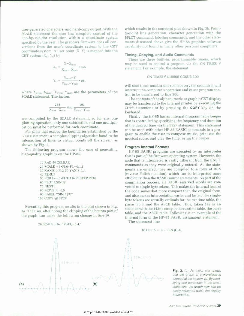
user-generated characters, and hard-copy output. With the SCALE statement the user has complete control of the 256-by-192-dot resolution within a coordinate system specified by the user. The graphics firmware does all con versions from the user's coordinate system to the CRT coordinate system. A user point (X, Y) is mapped into the CRT system (Xc, Yc) by
X Xmin X c = * 2 5 5
Xmax— X
Y c = ï max I
I max ï mil «191
where Xmin, Xmax. Ymin, Ymax are the parameters of the SCALE statement. The factors
255
X_ V - m a x A m i n and
191
I m a x I m i n
are computed by the SCALE statement, so for any one plotting operation, only one subtraction and one multipli cation must be performed for each coordinate.
For plots that exceed the boundaries established by the SCALE statement, a complex clipping algorithm handles the intersection of lines to virtual points off the screen, as shown by Fig. 2.
The following program shows the ease of generating high-quality graphics on the HP-85.
10 RAD @ GCLEAR 20 SCALE -6*PI,6*PI, -0.1,1 30 XAXIS O.PI/2 @ YAXIS 0,.l 40 PENUP 50 FOR 1= -6*PI TO 6*PI STEP PI/16 60 PLOT I,SIN(I)/I 70 NEXT I 80 MOVE PI, 0.5 90 LABEL "SIN(X)/X"
100 COPY @ STOP
Executing this program results in the plot shown in Fig. 3a. The user, after noting the clipping of the bottom part of the graph, can make the following change in line 20.
20 SCALE -6*PI,6*PI, -0.4,1
(a)
which results in the corrected plot shown in Fig. 3b. Point- to-point line generation, character generation with the BPLOT command, labeling commands, and the other state ments discussed above give the HP-85 graphics software capability not found in many other personal computers.
Timing, Copying , and Audio Commands There are three built-in, programmable timers, which
may be used to control a program via the ON TIMER # statement. For example, the statement
ON TIMER#1, 10000 GOSUB 300
will start timer number one so that every ten seconds it will interrupt the computer's operation and cause program con trol to be transferred to line 300.
The contents of the alphanumeric or graphic CRT display may be transferred to the internal printer by executing the COPY statement or by pressing the COPY key on the keyboard.
Finally, the HP-85 has an internal programmable beeper that is controlled by specifying the frequency and duration of the desired tone via the BEEP statement. This statement can be used with other HP-85 BASIC commands in a pro gram to enable the user to compose music, print out the musical score, and play the tune, using the beeper.
Program Internal Formats HP-85 BASIC programs are executed by an interpreter
that is part of the firmware operating system. However, the code that is interpreted is vastly different from the BASIC commands as they were originally entered. As the state ments are entered, they are compiled to a form of RPN (reverse Polish notation), which can be interpreted more efficiently than the BASIC source statements. As part of the compilation process, all BASIC reserved words are con verted to single-byte tokens. This makes the internal form of the code somewhat more compact than the original form, and also makes interpretation easier and faster. The single- byte tokens are actually ordinals for the runtime table, the parse table, and the ASCII table. Thus, token 142 is as sociated with the 142nd entry in the runtime table, the parse table, and the ASCII table. Following is an example of the internal form of the HP-85 BASIC assignment statement.
The statement line
10 LET A = B + SIN (OD)
I -• l
. . S I N '
\ , . / . \ I
(b) • t f \ - ~ t - - f - i t â € ” t â € ” 9
F i g . 3 . ( a ) A n i n i t i a l p l o t s h o w s t h a t t h e g r a p h o f a w a v e f o r m i s c l ipped at the bot tom, (b) By mod i fying one parameter in the SCALE s ta tement , the g raph now can be easi ly re located wi th in the display boundar ies.
JULY 1980 HEWLETT-PACKARD JOURNAL 29
© Copr. 1949-1998 Hewlett-Packard Co.

is converted to single-byte tokens as listed below.
2 0 B C D l i n e # 1 0 0
2 2 # b y t e s i n t h e l i n e 1 4 2 T o k e n f o r L E T
2 1 T o k e n f o r f e t c h v a r i a b l e a d d r e s s 4 0 A S C I I b l a n k
1 0 1 A S C I I A l T o k e n f o r f e t c h v a r i a b l e
4 0 A S C I I b l a n k 1 0 2 A S C I I B
1 T o k e n f o r f e t c h v a r i a b l e 4 0 A S C I I b l a n k
K i i A S C I I C 1 T o k e n f o r f e t c h v a r i a b l e
4 0 A S C I I b l a n k 1 0 4 A S C I I D
5 2 T o k e n f o r * 3 3 0 T o k e n f o r S I N
5 3 T o k e n f o r + 1 0 T o k e n f o r s t o r e n u m e r i c v a r i a b l e 1 6 E n d o f l i n e t o k e n
Preallocation One of the things that has traditionally made interpreters
slow is that they maintain a table of variables, which must be searched at runtime for each variable reference. In the HP-85 we have attempted to solve this problem by preallo- cation of all variable references. During the allocation pro cess, the variable names that occur in the internal RPN form
of the program are replaced by the relative addresses of the variables. Thus, at runtime, the interpreter has only to read an address and add it to the base address of the program to determine the absolute location of the variable being refer enced. For traditional interpreters the time required to ac cess any variable is dependent upon its position within the variable table. On the HP-85 all variables may be accessed in exactly the same amount of time.
User-defined functions are like variables in that they have names that look like variable names, and they have as sociated with them a value, much like a variable. Because of these similarities and the obvious advantages in runtime execution, user-defined functions are also preallocated.
In traditional interpreters , it is also necessary to search for all line number references. Thus execution speed is affected by how far the referenced line is from the beginning of the program or from the current line, depending on the im plementation. In the HP-85 all line number references are replaced by the relative address of the referenced line dur ing the allocation process, thus eliminating the need to search for referenced lines at runtime.
Output Control Flexible vectored control of output is provided in the
HP-85 operating system by an output control routine that acts like a police officer directing traffic. This routine is accessed by the user via the PRINTER IS and CRT IS state ments. Output information that normally goes to the CRT [output device 1) can be redirected to the internal printer
Fast Integer Processing The HP-85 implementation of BASIC provides INTEGER, SHORT, and
REAL considered type'declarations (undeclared variables are considered to be REAL) with this feature — many calculations are transparent to the user and proceed internal ly faster than might be expected when the values involved are integers, even though INTEGER type may or may not have been spec i f ied.
Let 's see how and when th is occurs. Memory space is conserved by a l l oca t i ng f o r each va r i ab l e no mo re space t han i s needed t o represent the range of values over which that type of variable can run (see Fig. 1a). In each of these cases, the var iable is in i t ia l ly tagged using one of the bytes to f lag i t as "nul l data" (a warning is issued to the user i f processing is attempted using nul l data). Now suppose, for example, a program init ializes a variable i=o so it is no longer null and subsequently performs the calculat ion 1=1+1, assuming no prior type declaration for I. By default, i is assumed REAL. It is easiest for the user to ignore type declarat ion when storage space is not a t a premium. The penalty for this in usual BASIC implementations is to force slower f loat ing point ca lcu lat ions, even though only in teger va lues may be involved. The HP-85 implementat ion avoids this penalty, when i t can, by using an addit ional special format — tagged integers.
When to value is assigned to a REAL variable, it is f irst examined to see i f i t is actual ly an integer (up to three bytes). I f so, i t is stored as
V a r i a b l e T y p e : I n t e g e r Short Real (declared or undeclared)
R a n g e : Â ± 9 9 9 9 9 Â ± 9 . 9 9 9 9 E Â ± 9 9 Â ± 9 . 9 9 9 9 9 9 9 9 9 9 9 E Â ± 4 9 9
(a)
shown in F ig . 1b and the subsequent ca lcu la t ion 1+1 w i l l p roceed much the s ince only smal l in tegers are involved. Should the integer become too large (more then f ive digits) or should some other port ion o f the and fo rce i to a w ider REAL fo rmat , i w i l l rema in REAL and subsequent ca lcu la t ions o f 1=1+1 wi l l p roceed accurate ly , but a t a s lower pace.
The fetch routine presents eight bytes (a REAL or tagged integer) to each integers, routine. Routines not interested specifically in integers, such as SIN and cos, cal l a conversion rout ine which checks for the t a g b y t e , a n d , w h e n n e c e s s a r y , c o n v e r t s t h e i n t e g e r t o t h e n o r mal ized REAL format . The add, subt rac t , and mul t ip ly rout ines ac t d i f f e r e n t l y . I f b o t h a r g u m e n t s a r e t a g g e d i n t e g e r s , f a s t i n t e g e r routines are employed, providing fast counting in FOR-NEXT loops and other instances as ment ioned.
When process ing o f a math rout ine is completed, cont ro l is re l in qu ished to the sys tem. I f the resu l t i s to be s to red in memory , the recipient variable is checked and the eight-byte result is converted, i f necessary , to the appropr ia te one o f the fo rmats shown in F ig . 1 before storage. Should the answer exceed the range for that variable type, a defau l t va lue is s tored and a range warn ing is issued.
Real ( tagged as integer)
Bytes Unused
1 Byte Tag
-Homer Russel l
F i g . 1 . ( a ) E a c h v a r i a b l e i s a l l o c a t e d s p a c e i n t h e m e m o r y a c co rd ing to i t s t ype spec i f i ca t ion , (b) If a REAL variable is perceived to b e a c t u a l l y a n i n t e g e r o f u p t o three bytes, i t is stored in memory a s s h o w n a n d p r o c e s s e d i n t e r nal ly as an integer.
3 0 H E W L E T T - P A C K A R D J O U R N A L J U L Y 1 9 8 0
© Copr. 1949-1998 Hewlett-Packard Co.

Output ( I /O ROM)
I /O ROM Output Handler
Fig. 4. An output control routine directs the output from PRINT D/SP, and LIST s ta tements to the se lected per iphera l . I f the pe r i phe ra l i s no t p resen t , t he rou t i ne ca l l s an app rop r i a te er ro r rou t ine . When add i t iona l per iphera ls a re added to the HP-85 sys tem the I /O ROM supp l ies an add i t iona l OUTPUT command and redirects the normal error subrout ine cal l f rom the output control rout ine to the appropriate subrout ine in the I/O ROM.
(output device 2) by the statement CRT IS 2. Similarly, out put information normally going to the internal printer can be redirected to the CRT by a PRINTER IS 1 statement. Nor mal CRT output information comes from DISP, LIST, and CAT statements and ERROR messages. Print output comes from PRINT, PLIST, and TRACE statements. Output device specifications other than 1 or 2 normally result in an error message. All output-producing statements set a select code, which the output control routine uses to direct the output from the producer to the target device (see Fig. 4). The operating system uses a select code of 0 as a flag for external I/O to increase throughput speed of multiple output calls to the output control routine, such as LISTings or OUTPUT statements with multiple parameters in the output list.
System Extensions Option locations or "hooks" in the operating system
allow extension of the HP-85 capabilities. An option loca tion is typically several RAM locations that the operating system accesses with a subroutine call or a single byte in RAM containing a flag with special meaning to the system. In the case of a subroutine call option, the RAM option location would be initialized to a subroutine return or an error message subroutine call. A plug-in ROM or binary program can "hook" into the operating system and take over some process in the system by inserting a subroutine call to itself in place of the default option location contents. For example, the output control routine discussed earlier attempts to send output for a select code other than 1 or 2 to
one of these locations. A plug-in ROM that handles the output to a peripheral device replaces the normal error call at the respective option location with a subroutine call pointing to its own output handling routine (see Fig. 4). Other locations in the operating system provide intercep tion of the keyboard processing routine, the system parser, the main idle loop, and external L'O interrupts. Special flags in the RAM option locations permit image and interrupt process extensions.
The FiP-85 option locations thus provide an easy means to expand the capabiliti es and extend the power of the basic computer.
Mass Storage The 98200A tape cartridge provides a digital-quality
storage medium for data and program storage and retrieval. A directory of file information at the front of the tape im mediately provides the location and length of any of up to 42 files on the tape.6 A high-speed search technique gives the user fast access to files, with the six-character file name providing a friendly reference not commonly found in per sonal computers. This directory can be readily displayed using the CATalog command. Four levels of file security provide protection of sensitive or important information on the tape. The user can prevent duplication and listing of program files and access to data files that contain private information. A soft write-protect security prohibits acci dental replacement of valuable files.
The data files can be structured by the user to be any number of records, each of a specified size up to 3 2 767 bytes long, limited only by the mass storage space available (210K bytes for each tape cartridge). The data files can be accessed both serially and randomly, giving the user complete con trol over retrieval techniques and access speed for data. The records within a file are treated as logical length records and can be addressed directly by specifying the numbers of their positions within the file. The firmware transparently handles the physical record divisions for the user.
Language Extensions The BASIC language as implemented on the HP-85 can be
extended by the addition of either plug-in ROMs or binary programs. HP-85 memory consists of 32K bytes of ROM and 16K bytes of RAM. The last 8K bytes of the ROM is bank- selectable. A plug-in module allows expansion of the RAM to 32K bytes.
Plug-in ROMs map into the bank-selectable portion of system ROM, and binary programs load into the RAM. There may be up to six plug-in ROMs and one binary pro gram in the system at any one time. Binary programs are loaded by the LOADBIN command and stored by the STORE- BIN command, and reside in the highest memory locations of the RAM. They have a somewhat rigid structure in that all relocatable addresses are contained in a block at the begin ning of the program and are relocated by the LOADBIN command. The remainder of the binary program must be written as "run anywhere code."
The structures for ROMs and binary programs are similar in that they require the same table structure at the begin ning. The first two bytes of each ROM contain the ROM number and its complement. The first two bytes of a binary program contain the address at which the binary is loaded.
JULY 1980 HEWLETT-PACKARD JOURNAL 31
© Copr. 1949-1998 Hewlett-Packard Co.

Nelson A. Mi l ls Joining HP in 1 976, Nelson Mills worked on the HP-85 opera t ing sys tem and in te rp re te r . He i s now the p ro jec t man ager for h igh-end f i rmware at the Cor- val l is Div is ion. Af ter receiv ing a BS in mathemat ics f rom Alb ion Col lege, Mich igan in 1961, Nelson spent f ive years in the U.S. Navy and then worked for ten years as a systems programmer. He and his family — wife and two children — live in Corvallis, Oregon. Outside of working hours Nelson enjoys pho tography , h ik ing , camping , and coaching basketbal l and AYSO soccer.
Kent R. Henscheid After earning a BS in Mathemat ical Sci ences from Stanford University in 1973, Kent Henscheid jo ined HP as an appl i cat ions engineer. In late 1975 he went back to S tanford and rece ived the MSEE degree in 1976. S ince then he has worked on the f i rmware for the HP-85 and recen t l y has become i n volved with product marketing. Kent is a co- inventor for a patent re la ted to the HP-22 pocket calculator and is a nat ive of Pocatello, Idaho. He and his wife l ive in Corvall is, Oregon, have one son, and are expecting a new addit ion to the fam i ly . Outs ide of work ing hours, Kent en
joys mus ic , hunt ing , f i sh ing , camping and sk i ing .
The next ten bytes of both ROMs and binary programs contain, in order, the runtime table address, the ASCII table address, the parse table address, the error message table address, and the address of the initialization routine.
For binary programs, this block of table addresses is fol lowed by the runtime table and the parse table, since they also contain addresses that must be relocated.
Acknowledgments We would like to thank George Fichter who was project
manager in charge of software development for the HP-85, and who did much of the design and implementation of the
Homer C. Russel l '• At HP since 1969, Homer Russell ini- ' t ia l ly worked on market ing appl icat ions
and la ter became a market ing product suppor t manager . Subsequent ly , he has worked on HP-85 mathemat i cs a l gor i thm deve lopment and imp lementa t ion and now is a project leader for the HP-85 Matr ix ROM. Before jo in ing HP, he worked on orb i ta l analys is for the Apol lo program and as a computer sys tems engineer. Homer is a co- inventor for a patent on the 9820 Computer . Born in Phelps, Kentucky, he earned a BS in physics f rom the Univers i ty of Texas (E l Paso) in 1961 and an MA in
mathemat ics f rom the Univers i ty of Cal i forn ia at Berkeley in 1966. Homer is married with twochildren, a son and a daughter, and l ives in Corvall is, Oregon. When he isn't home with his family working out in t he i r t o r oom o r r e l ax i ng i n t he i r sauna and ho t t ub , he l i kes t o play racquetbal l , look for Indian rel ics, or read about mathemat ics, investment analysis, and nutr i t ional studies.
operating system and interpreter. Wan Cheng Chan de veloped the self-test function and the diagnostic ROM. Dennis Harms and Professor W. Kahan contributed to the implementation of the mathematical functions. Bill Kemper, Dan Harrington, and Peter Bock were responsible for the development of the applications software, and Con stance Jackson wrote the HP-85 Owners Manual.
References 1. D.W. Harms, "The New Accuracy: Making 23 = 8", Hewlett- Packard Journal, November 1976. 2. W.E. Egbert, "Personal Calculator Algorithms I: Square Roots", Hewlett-Packard Journal, May 1977. 3. W.E. Egbert, "Personal Calculator Algorithms II: Trigonometric Functions". Hewlett-Packard Journal, June 1977. 4. W.E. Egbert, "Personal Calculator Algorithms III: Inverse Trigonometric Functions", Hewlett-Packard Journal, November 1977. 5. W.E. Egbert, "Personal Calculator Algorithms IV: Logarithmic Functions", Hewlett-Packard Journal, April 1978. 6. W.A. Hanna, "Mass Storage Management — A Unified Ap proach," Hewlett-Packard Journal, June 1980.
Address Cor rec t ion Reques ted Hewle t t -Packard Company , 1501 Page
Road, Palo Al to , Cal i forn ia 94304
H E W L E T T - P A C K A R D J O U R N A L
Bulk Rate U.S. Postage
Paid Hewlett-Packard
Company
J U L Y 1 9 8 0 V o l u m e 3 1 â € ¢ N u m b e r 7
Technica l In format ion f rom the Laborator ies of Hewlet t -Packard Company
Hewle t t -Packard Company , 1501 Page Mi l l Road Palo Al to, Cal i fornia 94304 U.S.A.
Hewle t t -Packard Cent ra l Ma i l ing Depar tment Van Heuven Goedhar t laan 121
1180 AM Amste l veen The Ne the r lands ogawa-Hewler t -Packard L td . , Sug
Tokyo 168 Japan
C H A N G E O F A D D R E S S : : o change you r add ress o r de le te you r name f rom ou r ma i l i ng l i s t p lease send us you r o ld add ress l abe l Send c h a n g e s 6 0 d a y s . J o u r n a l , 1 5 0 1 P a g e M i l l R o a d , P a l o A l t o , C a l i f o r n i a 9 4 3 0 4 U . S . A . A l l o w 6 0 d a y s .
© Copr. 1949-1998 Hewlett-Packard Co.