karnatak law society’s gogte institute of technology was
TRANSCRIPT

Gogte Institute of Technology was established in 1979
by Karnatak Law Society, Belagavi. Its five departments are
accredited by NBA till 30-06-2021. It is NAAC accredited
with A+ till 01-12-2021 for 5 years. It has established the
name and fame in the region of north Karnataka. Gogte
Institute of Technology is known for its green campus,
excellent infrastructure and dedicated faculty. The campus
placements are exemplary good attracting good and studious
students.
The department of Electrical and Electronics
Engineering started in the year 1979. It has four-year
undergraduate course in Electrical and Electronics Engineering
and Research Centre. The department is accredited by NBA,
New Delhi for Three years’ till 30-06-2021 with NAAC
accreditation of A+ till 01-12-2021 for 5 years.
Rooftop Solar Power Plant of 450kW capacity
Estd. : 1939
Karnatak Law Society’s
GOGTE INSTITUTE OF TECHNOLOGY
Belagavi 590008, Karnataka, India
www.git.edu
Estd. :1979
Department of Electrical and Electronics Engineering
Equipment & Facility Catalogue for
Research & Consultancy
2020-2021

At present there are 17 faculty members and around 300
students. Currently ten Research Scholars are pursuing their
research in the department in the areas of Power Systems,
Renewable Energy, Flexible Alternating Current Transmission
System, Smart Grids, and Power Quality etc.
The department has played a key role in making GIT well
known amongst the technical colleges due to its excellent
infrastructure, placement and outcome based education.
Department offers the UG and Research programs:
UG (B.E.) – Electrical & Electronics Engineering with intake of
60.
Research Center – PhD Program.
Vision
Department of Electrical and Electronics Engineering
focuses on Training Individual aspirants for Excellent Technical
aptitude, performance with outstanding executive caliber and
industrial compatibility
Mission
To impart optimally good quality education in academics and real
time work domain to the students to acquire proficiency in the
field of Electrical and Electronics Engineering and to develop
individuals with a blend of managerial skills, positive attitude,
discipline, adequate industrial compatibility and noble human
values.
Sl.
No.
Lab Name & Equipment Details
Page
No.
1. 1.1
1.2
1.3
1.4
High Voltage Engineering Lab
High Voltage Testing
Transformer Oil Testing
Field Plotter
Power Quality Analyzer
1-2
3-4
5
6
2.
2.1
2.2
2.3
2.4 2.5
Transformer and Electrical Machine Lab
Single Phase and Three Phase
Transformer
DC Machines
Synchronous Machine
Motor Generator Set
Rectifier unit
7
8
9
10
11
3.
3.1
3.2
3.3
Power System Lab
Power System Protection Schemes
Numerical 3 – Phase Over Current &
Earth Fault Relay
Microprocessor based over/under
voltage Relay
12
13-14
15
4. 4.1
4.2
4.3
4.4
4.5
4.6
4.7
4.8
Power Electronics Lab Single Phase PWM Inverter UJT Firing Circuit
Digital Firing Circuit Stepper Motor Control SCR, DIAC &TRIAC Characteristics Study
Unit CSU
MOSFET and IGBT Characteristics Study
Unit CSU
Single Phase Converter Firing Unit SCT
DC-Motor Speed Control Unit
16
17-18
19-20
21-22
23-24
25-26
27-28
29-30

5. 5.1
Embedded Systems Lab
ARM Cortex M3 Evaluation Board
31-32
6. Analog Electronics Lab 33
34
35
36
6.1 Digital Trainer Kit
6.2 Cathode Ray Oscilloscope [CRO]
6.3 Function Generator
6.4 DC Power Supply (Regulated)
Impulse test setup with different electrodes with
impulse voltage capacity of kV.
Specifications:
Input AC Voltage
DC Voltage
Impulse Voltage
200kV AC voltage
280 kV DC Voltage
280kV Impulse Voltage
Equipment Catalogue | Department of Electrical & Electronics Engineering, KLS GIT Belagavi.
2
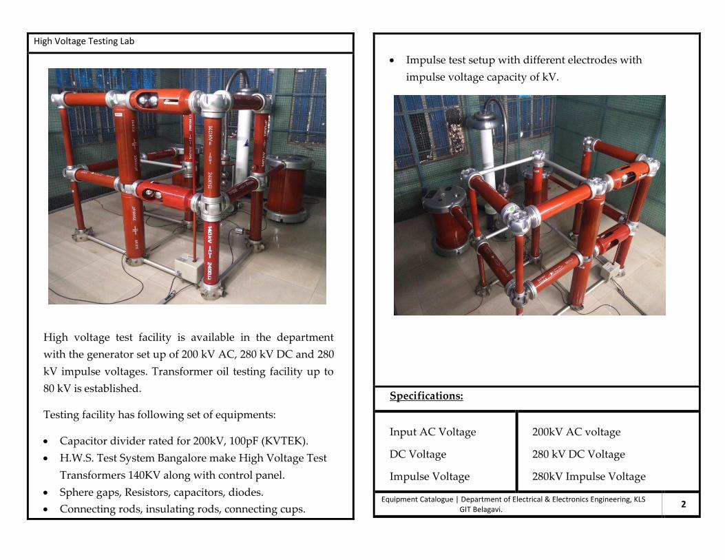
High Voltage Testing Lab
High voltage test facility is available in the department
with the generator set up of 200 kV AC, 280 kV DC and 280
kV impulse voltages. Transformer oil testing facility up to
80 kV is established.
Testing facility has following set of equipments:
Capacitor divider rated for 200kV, 100pF (KVTEK).
H.W.S. Test System Bangalore make High Voltage Test
Transformers 140KV along with control panel.
Sphere gaps, Resistors, capacitors, diodes.
Connecting rods, insulating rods, connecting cups.

As transformer oil deteriorates through aging and moisture
ingress, transformer oil should, depending on economics,
transformer duty and other factors, be tested periodically.
Electric utility companies have a vested interest in periodic oil
testing because transformers represent a large proportion of their
total assets.
Through such testing, transformers' life can be substantially
increased, thus delaying new investment of replacement
transformer assets.
Equipment Catalogue | Department of Electrical & Electronics Engineering, KLS GIT Belagavi.
4
Transformer Oil Testing Lab
Transformer oil, a type of insulating and cooling oil used
in transformers and other electrical equipment, needs to
be tested periodically to ensure that it is still fit for purpose. This is
because it tends to deteriorate over time. Testing sequences and
procedures are defined by various international standards, many of
them set by ASTM. Transformer oil testing consists of
measuring breakdown voltage and other physical and chemical
properties of samples of the oil, either in a laboratory or using
portable test equipment on-site.
Why testing:
The transformer oil (insulation oil) of voltage transformers and
current transformers fulfills the purpose of insulating as well as
cooling.
Thus, the dielectric quality of transformer oil is essential to
secure operation of a transformer.

Power Quality Analyzer
Power Quality Analyzer EN50160 Mode:
It is available on Ver1.30 or later. When this mode is selected,
the measurement function for EN50160 is added to the normal
mode, and some functions in normal mode will be limited.
When EN50160 mode is selected, the detailed data for
EN50160 is saved into the PC card in real time, and only data
for the display is saved in the internal memory.
Equipment Catalogue | Department of Electrical & Electronics Engineering, KLS GIT Belagavi. 6
Field Plotter Hive Volta
The use of electrolytic devices for this purpose is well known. These
devices employ a pair of electrodes which are immersed into
an electrolytic solution contained in a tank. Successive null point
readings, i.e. equipotential points, are taken at various points between
the electrodes.
Equipment Catalogue | Department of Electrical & Electronics Engineering, KLS GIT Belagavi. 5

DC Machines
A DC motor is an electric motor that runs on direct current power. In
an electric motor, the operation is dependent upon simple
electromagnetism. A current-carrying conductor generates a
magnetic field, when this is then placed in an external magnetic field,
it will encounter a force proportional to the current in the conductor
and to the strength of the external magnetic field. It is a device which
converts electrical energy to mechanical energy. It works on the fact
that a current-carrying conductor placed in a magnetic field
experiences a force which causes it to rotate with respect to its
original position.
Specifications:
Input AC Voltage - 200V AC voltage
DC Voltage - 0 to 200V DC Voltage
Equipment Catalogue | Department of Electrical & Electronics Engineering, KLS GIT Belagavi. 8
Single Phase and Three Phase Transformer
A single-phase or three-phase transformer is an electrical
device that accepts single-phase AC power and outputs
single-phase AC. This is used in the distribution of power in
non-urban areas as the overall demand and costs involved are
lower than the 3-phase distribution transformer. They are
used as a step-down transformer to decrease the home
voltage to a suitable value without a change in frequency. For
this reason, it is commonly used electrical power appliance at
residences.
Specifications:
Single Phase transformer
Primary AC Voltage –
230 V
Secondary AC Voltage –
0v to 230V variable
Three Phase transformer
Primary AC Voltage –
415 V
Secondary AC Voltage –
0v to 415V variable
Equipment Catalogue | Department of Electrical & Electronics Engineering, KLS GIT Belagavi. 7

Motor Generator Set
A motor generator (M-G) set refers to a composite device consisting
of a motor and a generator mechanically coupled through the common
shaft. Practically a motor generator set is a system where a motor and
a generator are connected or rather placed in a single circuit. It is a
device used to convert electrical power from one form to another.
That is mainly it converts electrical power to any other type of power.
Specifications:
Alternator:
5KVA, 4Kw, 0.8pf, 415volts,
7A,50Hzs, 1500rpm
Field current=2.4A
DC Motor:
3.7Kw, 220V, armature
current 26.1A,
1500rpm,
Field current 2.4Amps
Equipment Catalogue | Department of Electrical & Electronics Engineering, KLS GIT Belagavi.
10
Three Phase Slip Ring Induction Motor
The slip ring induction motor could be used for industrial wires
where variable speed and high starting torque are prime
requirements. The stator of slip ring induction motor is very much
the same as that of the squirrel cage induction motor, but the
construction of its rotor is very much different. Stator winding can
be either star or delta connected depending upon the design.
Induction with this type of rotor is having three phase double layer
distributed windings. Insulated enameled copper wires are used for
coils.
Specifications:
Input AC Voltage
Input Current
420V AC voltage
0 Amp to 20 Amp
Equipment Catalogue | Department of Electrical & Electronics Engineering, KLS GIT Belagavi. 9

Power System Protection Schemes
IDMT Relay (Inverse Definite Minimum Time Relay) is
protection relay. They are used on transmission lines to see to that the
line current doesn't exceed safe values and if it does, triggers the circuit
breaker. IDMT means inverse definite minimum time.
Use of IDMT relay:
The relay will not operate when the value of current is less than the
pick value. The relay is used for the protection of the distribution lines.
The inverse time relay is of three types. The relay whose operating
time is approximately proportional to the fault current is known as
the IDMT relay.
Equipment Catalogue | Department of Electrical & Electronics Engineering, KLS GIT Belagavi. 12
Rectifier unit
A rectifier is an electrical device that converts alternating current,
which periodically reverses direction, to direct current, which
flows in only one direction. The process is known as rectification.
The rectifier unit provided here has an input of 415v 50Hz AC
which delivers an output of 200V, up to 80 Amp of current in
DC.
Specifications:
Input AC Voltage
DC Output Voltage
Output DC Current
415V AC voltage
200V DC Voltage
Up to 80Ampere
Equipment Catalogue | Department of Electrical & Electronics Engineering, KLS
GIT Belagavi. 11
Enhanced system reliability and availability due to continuous
hardware and software self-supervision with auto-diagnosis.
Powerful software support for setting of the relay and for
recording of relay parameters with a portable PC.
Application:
The combined over current and earth-fault relay SPAJ 140 C is
intended to be used for the selective short-circuit and earth-fault
protection of radial feeders in solidly earthed, resistance earthed or
impedance earthed power systems.
The integrated protection relay includes a phase over current unit
and an earth-fault unit with flexible tripping and signaling
facilities.
The over current and earth-fault relays can also be used in other
applications requiring single-, two or three-phase over current
protection and non-directional earth-fault protection.
The combined over current and earth-fault relay also features
circuit breaker failure protection.
Specifications:
Equipment Catalogue | Department of Electrical & Electronics Engineering, KLS GIT Belagavi. 14
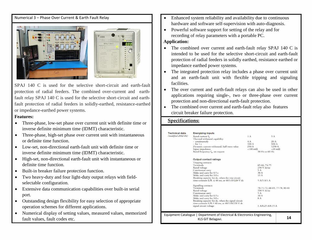
Numerical 3 – Phase Over Current & Earth Fault Relay
SPAJ 140 C is used for the selective short-circuit and earth-fault
protection of radial feeders. The combined over-current and earth-
fault relay SPAJ 140 C is used for the selective short-circuit and earth-
fault protection of radial feeders in solidly-earthed, resistance-earthed
or impedance-earthed power systems.
Features:
Three-phase, low-set phase over current unit with definite time or
inverse definite minimum time (IDMT) characteristic.
Three-phase, high-set phase over current unit with instantaneous
or definite time function.
Low-set, non-directional earth-fault unit with definite time or
inverse definite minimum time (IDMT) characteristic.
High-set, non-directional earth-fault unit with instantaneous or
definite time function.
Built-in breaker failure protection function.
Two heavy-duty and four light-duty output relays with field-
selectable configuration.
Extensive data communication capabilities over built-in serial
port.
Outstanding design flexibility for easy selection of appropriate
operation schemes for different applications.
Numerical display of setting values, measured values, memorized
fault values, fault codes etc.

Single Phase PWM Inverter
Inverters convert DC power to AC power at a desired output voltage
and frequency and in most of the inverters both are required to be
controlled AC output voltage is built by using semiconductor devices
as switches and hence circuits with fewer components have non
sinusoidal output wave form.
Inverters are used for Variable speed AC motor drives, Induction
heating; Aircraft power supplies, UPS for important applications such
as Computers.
In PWM inverter power module four IGBTs are used The devices are placed inside and the terminals are to front panel.
Specifications: IGBTs: IRGP30BI2Z0KDE (with ultra soft recovery diodes)
VCE - 1200 V VCE(ON) - 2.28 V
Switching speed - 1 K Hz
Max. Allowable average curren-2A DC
Max. Allowable dc supply voltage - 220 V DC @1 A
Operating frequency - 40Hz to 60 Hz
Ic - 25 mA ; VGE - I5V ps
Equipment Catalogue | Department of Electrical & Electronics Engineering, KLS GIT Belagavi. 16
Microprocessor based over/under voltage Relay
Relay MV12 is a single phase, over voltage or Under voltage
relay with one measuring element. The relay can be used for feeder
protection in all low voltage, medium voltage and high voltage sub-
stations. DIP switches are provided on the front panel for pick up and
time delay settings.
Specifications:
Equipment Catalogue | Department of Electrical & Electronics Engineering, KLS GIT Belagavi. 15

d) Single phase AC phase control using SCRs — 2 SCR’s.
e) Single phase AC phase control using Triac.
Specifications:
1. POWER : AC Supply ON/OFF switch to the unit with built in
indicator
2. 20 -0-20V/1A AC supply for UST relaxation oscillator.
SCR firing from a step down transformer.
3. Dz : Zener diode — 15V/1 Watt. To limit the supply to UJT.
4. Rc : Potentiometer to vary the firing angle.
5. UJT : 2N 2646.
6. B1, B2, E : Base - I, Base- 2 and Emitter points of UJT.
7. T1 & T2 : Pulse Transformer isolated pulse O/ps to trigger SCRs.
8. SCRs T1 & T2: TYN616-16A/600V, A-Anode, K-cathode & G —
Gate points.
Equipment Catalogue | Department of Electrical & Electronics Engineering, KLS GIT Belagavi.
18
UJT Firing Circuit
DESCRIPTION :
This unit consists of the following components to study firing of SCR
using UJT relaxation oscillator.
a) A step down transformer — 20V -0-20V/ 1A.
b) UJT relaxation oscillator circuit.
c) Pulse transformer isolation for SCR triggering. d) SCRs.
This unit can be used to trigger a triac and also 2 SCRs in the
following power circuits.
a) Single phase Half wave converter — 1 SCR.
b) Single phase Full wave converter — 2 SCRs.
c) Single phase Half controlled bridge converter - 2 SCR’s & 2 diodes.

8. Fe OSCILLATOR Carrier frequency generator - 5khz.
9. R : 10k ohms potentiometer to vary the no. of pulses from the clock
generator.
10. CLOCK Generator astable oscillator to generate clock input to the
counter (180 pulses or 100 pulses).
11. COUNTER: 3 stage -4 bit up / down programmable counter.
12. LOGIC CIRCUIT: Logic and modulator circuit to get Tp; Tn for
1ph converter and I\y/ T, for chopper experiments.
Tp Train of pulses for +ve half cycle.
Tn Train of pulses for -ve half cycle.
Tm: Pulse of 200 u sec for main SCR.
Ta: Pulse of 200 y sec for auxiliary SCR.
13. TM- : ON/OFF switch for main SCR.
14. PULSE TRANSFORMER
15. INPUT 1 and 2 Input Terminals to connect logic inputs.
16. TRIGGER O/Ps : Pulse Transformer isolated Trigger O/Ps to be
connected to gate and cathode of SCRs.
Equipment Catalogue | Department of Electrical & Electronics Engineering, KLS GIT Belagavi.
20
Digital Firing Circuit
This firing circuit generates isolated trigger pulses for 1-phase
converter, Triac and DC Chopper Power Circuit. The firing angle can
be varied from 0-180" with 1° resolution and duty cycle can be varied
from 0-100 % with 1 % resolution using thumb wheel switches. The
firing scheme is based on ZCD, fixed frequency line synchronized
clock generator, up-down counter, flip flop and pulse Transformer
isolation method..
IC 74121- Mono stable oscillator is provided to generate a pulse of
duration 100pScc — which can be used for chopper experiments and
also used for 1-phase half wave converter experiments.
Specifications:
1. MAINS: Power ON/OFF switch to the unit with built-in Indicator.
2. AC REF : 10V AC reference input for Synchronization.
3. GND Ground point of the unit to observe the waveforms.
4. A : ZCD output.
5. C Reset output for resetting the counter.
6. F.A. / D.CY : Thumb wheel switch to set the firing angle from 0
to180° and Duty cycle from 0 to 100%.
(chopper) mode.

d) ENT :- To enter the set values :
e). RUN/STOP -- To start and stop the stepper motor
4.+V :- 5V/2Amps DC supply for Stepper Motor. (Built in) 2
5.+5 V -. 5V For Control Circuit. (Built in)
6. GND : :- Supply ground point
7, FUSE -- 2 Amps fast below glass fuse for short circuit protection
8. A1, A2, B1, B2:- Output points to connect to the Al,A2,B1, &
B2 leads of stepper motor.
9, LED’s -- To indicate the status of output.
Equipment Catalogue | Department of Electrical & Electronics Engineering, KLS GIT Belagavi. 22
Stepper Motor Control
This unit is microcontroller based controller circuit to accurately
generates pulses to energize the stepper motor winding in the desired
sequence Power transistor based driver circuit to drive the stepper
motor from this controller we can set the speed of stepper motor in rpm
, set the number of steps the motor can move .We can set the direction
of rotation –forward and reverse direction. We can also set Half step
and full step mode
Specifications:
1. Mains :- Power ON/OFF switch to the unit with built-in indicator
2. DISPLAY:- Seven segment 5 digit display to display the parameter
and values. ;
3. KEY BOARD :-
a) SET :- To set the Parameter fol
b) INC :-- To increment the set parameter values =
c) DEC -- To decrement the set parameter values 3

6. SCR ; TYN 616.
7, TRIAC : BT 136. HO
8. DIAC : DB-3-32 Volts breakdown voltage.
9. V2 ~ : Potentiometer to vary the Gate voltage.
10. ON - Switch for V2.
11. Fuse ; 250 mA Glass fuse.
12. +&- : Positive and Negative points of power supply V2.
13. R1: Load potentiometer-4 K ohms/25 watts in scrics with 753 ohm
Resistor.
14. R2 : Gate potentiometer-10 K ohms/3 watts in series with 75 ohm
Resistor.
Equipment Catalogue | Department of Electrical & Electronics Engineering, KLS GIT Belagavi.
24
SCR, DIAC and TRIAC Characteristics Study Unit CSU
This unit mainly consists of the following power semiconductor
devices a) SCR - TYN 616; b) TRIAC - BT 136; c)DIAC - DB3
Whose characteristics is to be studied .
A variable DC power supply using LM317 regulator to vary the load
voltage From 2.5 Volts to 35 volts approximately. One more variable
DC power supply using LM317 regulator to vary the Gate Voltage
from 1.5 volts to 15 Volts approximately. Switch and fuse is provided
in series with both the power supplies. A potentiometer of 25 watts is
provided to vary the load current. A potentiometer of 3 watts is
provided to vary the Gate current.
Specifications:
1. Mains Power ON/OFF switch to the unit with built in indicator.
2. V1: Potentiometer to vary the load voltage.
3. ON - Switch for V1.0.
4. FUSE - 600 mA glass fuse for V1.
5. +&- : Positive and Negative points of power supply VI.

8. V2 Potentiometer to vary the Gate voltage.
9. ON: Switch for V2.
10. Fuse, 250 mA Glass fuse.
11. Positive and Negative points of power supply V2.
12. R1 - - Load potentiometer+ K ohms/25 waits in series with 75 ohm
Resistor. : :
13. R2 - Gate potentiomcter-10 K ohms/3 watts in scrics with 75 ohm
Resistor.
Equipment Catalogue | Department of Electrical & Electronics Engineering, KLS GIT Belagavi.
26
MOSFET and IGBT Characteristics Study Unit CSU
This unit mainly consists of the following power semiconductor
devices. a) MOSFET - IRF 740, b) IGBT - — IRGBC20S, whose
characteristics is to be studied.
A variable DC power supply using, LM317 regulator to vary the load
voltage From 2.5 to 35 volts approximately. One more variable DC
power supply using LM317 regulator 15 volts approximately. Switch
and fuse is provided in series with both the power supplies. A
potentiometer of 25 watts is provided to vary the load current. A
potentiometer of 3 walls Is provided to vary the Gale current.
Specifications:
1. Mains: Power ON/OFF switch to the unit with built in indicator
2. V1- Potentiometer to vary the load voltage.
3. ON - Switch for V1.
4. FUSE - 600 mA glass fuse for V1.
5. Positive and Negative points of power supply V5
6. MOSFET - IRF 740.
7. IGBT -IRGBC20S.

Specifications:
1. Power -- Mains on/off Switch with built in LED Indicator.
2. Firing angle -. Potentiometer to very the firing angle from 180deg to
0 deg when the control switch is in INT position.
1. Control -- Switch for internal (INT) or external/feedback
2. (EXT) selection.
3. Vc -. External control input when the control switch is EXT
selection - 0 -5V.
4. GND -- Equipment ground for connecting external control
5. Input and to observe the test points.
6. ON/OFF -. Switch for trigger output with soft star: feature.
7. Test points -. To observe the signals at various points in the logic
Circuit for study purpose.
8. Trigger outputs – T1 & Tl’ - For +ve Half Cycle.
9. T2 & T2’ - For -ve Half Cycle.
Equipment Catalogue | Department of Electrical & Electronics Engineering, KLS GIT Belagavi. 28
Single Phase Converter Firing Unit SCT
This unit generates four line synchronized isolated triggering pulse to
fire thyristors connected in single phase (1) Half wave (2) Full wave
(3) half controlled Bridge (4) Fully controlled Bridge and (5) AC phase
control power circuit.
The firing circuit is based on Ramp-comparator scheme. Isolation is
provided by pulse Transformer.
FEATURES :-
1. Works directly on 230V AC mains.
2. Gate drive current of 200ma to trigger wide range of devices.
3. Provision for feedback control.
4. Firing angle variation from 180deg to 0 deg on a graduated scale.
5. Test points to study the log. circuit.
6. Soft start and soft stop feature.
7. Neatly designed front panel.
This unit along with our SCR converter modules, Rectifier diode
modules, Single phases half controlled converter -power circuit and
single phase fully controlled converters power circuit can be used to
conduct Power Electronics Experiments on single phase.

Specifications:
(Power Circuit) FRONT PANEL DETAILS:-
1. Digital Voltmeter to measure DC voltage.
2. Digital Ammeter to measure DC current
3. IGBT -- Insulated Gate Bipolar Transistor
4. MOSFET -- JRF 249
5. FIELD -- Field supply 220 V + 10% @ 2Amp for field of DC shunt
220V DC motor with neon lamp indicator.
06. VOLT SELECT:- Rotary switch to select DC supply as follows.
OFF: - DC supply is OFF.
l --24V DC.
2 -- 48VDC.
3 -- 1IOVDC.
4 -- 220V DC
08. Transformer: - Step down transformer with tappings 20V, 40V,
80V and 170Volts to get different DC output Voltages.
09. RECTIFIER: - Diode bridge rectifier -10Amps/600V to rectify
input AC supply to DC supply.
10. C: - Capacitor filter.
(Control Circuit)FRONT PANEL DETAILS:-
1. Mains -- Power ON/OFF switch to the unit with built in indicator.
2. LCD display: - 2 line x 16 characters LCD display to display the
parameters.
3. Key board - .
Equipment Catalogue | Department of Electrical & Electronics Engineering, KLS GIT Belagavi.
30
DC-Motor Speed Control Unit
This trainer kit consists of two parts a)Power circuit and b)Control
circuit to study the speed control of DC motor.
(A) Power circuit: - The power circuits mainly consists of Power
MOSFET. IGBT. a freewheeling diodes, and built in DC source for the
chopper circuit and Digital meters to measure DC voltage and current
POWER MOSFET (IRF-+69) and IGBT GRGPH20KD) freewheeling
diode are mounted on 4 suitable heat sink and protected by snubber
circuit and fuses. All the device terminals are brought out on the front
panel. Built in DC source is provided in the unit for input to the
chopper circuit.
(B) Control Circuit: - The control circuit is 89C51 microcontroller
based to accurately generate the control output. The duty cycle can be
varied from 0-100%, Frequency of the chopper can varied from 50Hz
to 500Hz. 2 line x 16 character LCD display to indicate the parameters
and their values. 4 keys to increment & decrement the chopper
frequency or Duty cycle and to Run/Stop the output with soft start and
stop feature. Optocoupler based driver circuit to drive MOSFET/IGBT.
processor is in the automotive industry. The Cortex-M3 processor
has very high-performance efficiency and low interrupt latency,
allowing it to be used in real-time systems. The Cortex-M3
processor supports up to 240 external vectored interrupts, with a
built-in interrupt controller with nested interrupt supports and an
optional MPU, making it ideal for highly integrated and cost
sensitive automotive applications.
Data communications: The processor’s low power and high
efficiency, coupled with instructions in Thumb-2 for bit-field
manipulation, make the Cortex-M3 ideal for many
communications applications, such as Bluetooth and ZigBee.
Industrial control: In industrial control applications, simplicity,
fast response, reliability are key factors. Again, the Cortex-M3
processors interrupt feature, low interrupt latency, and enhanced
fault-handling features make it a strong candidate in this area.
Consumer products: In many consumer products, a high-
performance microprocessor (or several of them) is used. The
Cortex-M3 processor, being a small processor, is highly efficient
and low in power and supports an
Specifications:
ARM Cortex M3 Evaluation Board: bit processor with IC LPC1768
works on 5V DC supply.
ALS-SDA-ARM-CTX M3 (ARM CORTEX M3 LPC 1768
evaluation board with USB cable (10 Quantity)
ALS-SDA-ARM-CTX-M3 (ARM CORTEX M3 LPC 1721
evaluation board with USB cable (02 Quantity)
DC motor & Stepper motor: Controlled by LPC 1768 processor
working at 12V DC supply.
Power Supply: (5 volts, 1.5Amp, +/- 12V DC, 100mA) (02 Quantity).
USB to Serial Converter (02 Quantity).
Equipment Catalogue | Department of Electrical & Electronics Engineering, KLS GIT Belagavi.
32
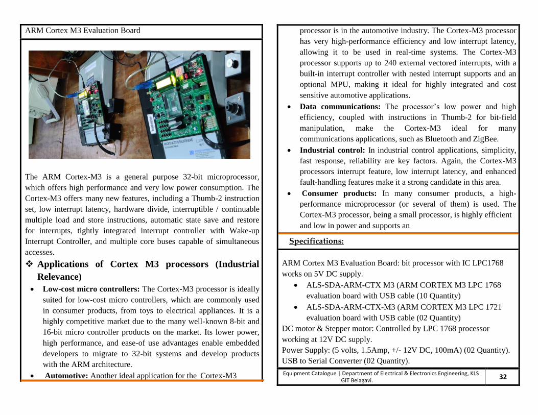
ARM Cortex M3 Evaluation Board
The ARM Cortex-M3 is a general purpose 32-bit microprocessor,
which offers high performance and very low power consumption. The
Cortex-M3 offers many new features, including a Thumb-2 instruction
set, low interrupt latency, hardware divide, interruptible / continuable
multiple load and store instructions, automatic state save and restore
for interrupts, tightly integrated interrupt controller with Wake-up
Interrupt Controller, and multiple core buses capable of simultaneous
accesses.
Applications of Cortex M3 processors (Industrial
Relevance)
Low-cost micro controllers: The Cortex-M3 processor is ideally
suited for low-cost micro controllers, which are commonly used
in consumer products, from toys to electrical appliances. It is a
highly competitive market due to the many well-known 8-bit and
16-bit micro controller products on the market. Its lower power,
high performance, and ease-of use advantages enable embedded
developers to migrate to 32-bit systems and develop products
with the ARM architecture.
Automotive: Another ideal application for the Cortex-M3

Cathode Ray Oscilloscope [CRO]
Cathode Ray Oscilloscope [CRO] is an essential instrument
in all electronic laboratories, for the detailed analysis or
examination of signals [ input, output or intermediate].
Two signals at a time can be observed or relationship
between the two signals can be observed and analyzed.
Measurement of voltage, current, frequency, phase shift
etc. can be carried out. CRO can also be used for
component tester.
Specifications:
Mains voltage
Mains Fluctuation
Power Consumption
Bandwidth
Time coefficient
Time Base
220-240V, 50Hz
+/- 10% max.
40VA
DC – 30 MHz
0.5µs/div to 0.2 s/div
18 calibrated steps
Equipment Catalogue | Department of Electrical & Electronics Engineering, KLS GIT Belagavi. 34
Digital Trainer Kit
Digital Trainer Kits provided with two different levels of
regulated power supply [-5v to 0v to +5v] & [-15v to 0v to
+15v]. It is used for the verification of Logic gates or can
also be used for analyzing digital circuits. Both Logic
circuits and digital circuits are made up of integrated
circuits (IC’s) of 74XX TTL family. It can be used for
rigging- up complex circuits using two or more numbers of
IC’s at a time. Trainer kits provide needful flexibility for
conducting experiments.
Specifications:
Input voltage to trainer kit
Output voltage of trainer kit
Fixed DC voltage
Ripple & Noise
Load & Line Regulation
230 Volts AC
5 volts at 0.5Amps
+/- 15 volts
<2.5mV
+/- 0.1%
Equipment Catalogue | Department of Electrical & Electronics Engineering, KLS GIT Belagavi.
33

DC Power Supply (Regulated)
Electronic circuits needing stable DC power supply of
different levels, for example biasing requirements of
transistor amplifier or to study the device characteristics
one way require variable DC in such cases Knob can be
operated to assign different levels of the voltage. Either
due to source variation or load variation the voltage level
may get affected therefore there is need of regulated DC
power supply.
Specifications:
Input AC Voltage
Regulated DC Voltage
Current
Type of regulation
230 volts
0 to 30 volts variable
0 – 5 Amps
Voltage or current
Equipment Catalogue | Department of Electrical & Electronics Engineering, KLS GIT Belagavi.
36
Function Generator
Function Generator also identified as signal generators are
used for various experimentations where indentified
signal/signals are to be processed. Signal generator can be
used to set desired signal of sine/triangular/square etc
cosine shape of different magnitudes and frequencies.
Specifications:
Frequency Range
Waveforms
Max. Amplitude
Power Requirement :
Line voltage
Consumption
Rotary Attenuation of
Sine Attenuation of
1Hz to 2MHz
Sine, Triangular, square,
variable duty cycle and
variable slope signals
20v (p-p), +/- 5%
230v AC +/- 10%, 50Hz
20VA
0,20,40,60 dB each
20dB
Equipment Catalogue | Department of Electrical & Electronics Engineering, KLS GIT Belagavi.
35

Karnatak Law Society’s
GOGTE INSTITUTE OF TECHNOLOGY
Belagavi 590008, Karnataka, India
Department of
Electrical and Electronics Engineering
Contact
Dr. D. B. Kulkarni
Professor and Head of Department
Electrical and Electronics
Tel: +91-831-2498501
Fax: +91-831-2441909
Email: [email protected]
INDUSTRY PARTNERS
Memorandum of Understanding
Department has Memorandum of Understanding with
Karnataka Power Transmission Corporation Limited
[KPTCL] and Hubli Electricity Supply Company Limited
[HESCOM] through which students get benefited for their
internship as part of the study for graduation.
STUDENTS CHAPTERS AND ASSOCIATIONS