kla-tencor p7 stylus profiler p7.pdf · kla-tencor p7-121016-05 3 5/19/17 use the appropriate...
TRANSCRIPT
KLA-Tencor P7-121016-05 1 5/19/17
Wisconsin Center for Applied Microelectronics
1550 Engineering Drive Phone: 608/262-6877
Madison, WI 53706 Fax: 608/265-2614
KLA-Tencor P7 Stylus Profiler
Material Restrictions: All materials on your sample must be on the “allowed materials list” for this tool before using it. NO EXCEPTIONS. It is the user’s responsibility to make sure that the material(s) they are putting in a tool is on the allowed materials list for that tool. Here is how to check the Allowed Materials list for WCAM tools:
1. Go to WCAM’s website at: http://wcam.engr.wisc.edu/
2. Click on the “Chemicals in the Lab” link.
3. Click on the link at the top of the page “LIST OF APPROVED MATERIALS”.
4. Scroll thru the document to find the tool you want to check the materials list for or hit Ctrl + F to bring up a search bar for the document and type in the tool’s name that you want to check the materials list for.
5. If the material(s) that you want to use in a tool are not on the approved list for that tool you may not put your sample in the tool. If you have no other way to process your sample and think it makes sense to use a particular material in a tool you may request that it be added to that tool’s material list by filling out the form on the “Chemicals in the Lab” webpage listed as “New Material Request Form”. Then email your material request form along with a MSDS for the material to the WCAM lab manager. The request will be reviewed by the WCAM advisory committee and you will get an email back from the lab manager approving or denying your material request for a particular tool.
KLA-Tencor P7-121016-05 2 5/19/17
1INSTRUMENT OVERVIEW
The KLA-Tencor P7 Profiler is a highly sensitive surface profiler that measures step height, roughness, and waviness on sample surfaces. The KLA-Tencor Profiler systems use stylus-based scanning to achieve high resolution.
The P7 system in WCAM is equip’d with the Standard head configuration.
The MicroHead V SR (standard range) has a vertical range of 327 um and is capable of scanning at forces between 0.5 and 50 mg.
The WCAM unit has a 2um radius tip with a 60° angle installed that limits the maximum force to 2 mg.
The system includes manual theta stage with stops at 45° increments and a fine theta adjustment of
± 5°.
Measurement of film stress is not supported at this time. Please use the Film Stress Tool.
Safety:
The unit has all moving parts enclosed. Do not operate the tool with the load door open.
Do not open the load door while the stage is moving.
Do not reach into the tool except to place your sample on the chuck. Do not put your
hands under the scan head, you could damage the stylus.
The Status Message Bar on the bottom of the screen may alert you to issues related to
safety.
Tool Limitations:
The performance of the tool is dependent on proper operation by the user and by not exceeding the
tool capability by trying to measure something that does not match the tool specs/capability. Do not
try to measure samples that are too thick and big in size for the instrument. Do not measure steps
heights that are beyond the range of the tool. Do not move the stage with the tip lower than the
sample top surface.
Sample Size requirements/restrictions:
Vertical range 0-327um
2um diamond stylus with a 60 degree cone angle.
Substrates sizes from 3mmx3mm up to 150mm in diameter
Maximum substrate thickness of 3mm. This would include the thickness of a sample holder used to position the sample on the chuck.
Maximum scan length of 150 mm. Limitations on materials. No uncured su8, no uncured PDMS, uncured PR, no soft
material that might stick to the stylus.
Do not measure any cantilevers or thin membranes, you may damage stylus.

KLA-Tencor P7-121016-05 3 5/19/17
Use the appropriate sample locators or jigs for your sample. If you find that your sample does not work with the established sample locators and jigs, contact the Staff tool owner to discuss your needs. A method to measure your samples will be worked out with you and then approved for use. DO NOT attempt to measure your sample using methods that have not been approved. You will lose your access to the tool if you do not follow procedures.
For the Small Samples Holders, the 2”x3” glass plate is about 1mm thick so the sample on it cannot
exceed 2mm for a total thickness <3mm (1mm + samples thickness < 2mm).
2PROTECTING THE STYLUS ARM ASSEMBLY
2System Provisions for Stylus Protection
The P7 Profiler incorporates several design features that protect the stylus from damage. (See Stylus Arm
Assembly Protection)
Tabl e 2. 2 Stylus Arm Assembly Protection
Protection Name Stylus Arm Protective Measure Description of Result
Data Point Saturation During an ascending scan, the scan is
terminated when the stylus reaches its
upper limit of travel (when it has pivoted
up as high as it can go)
The stylus automatically retracts and the scan
is terminated. In the Scan window, the trace
ascends and flat lines at the top of its range.
Lowest Elevator
Position
As a safety factor, the elevator can be
programmed to lower only to a preset
limit.
With the Lowest Elevator Position properly set,
when the measurement head is lowered, it
only goes as far as the setting allows, thus
protecting the stylus and sample from
damage.

KLA-Tencor P7-121016-05 4 5/19/17
2Potential Stylus Damage During Scans
Despite precautionary features, there are still circumstances where damage can occur.
Damage occurs whenever the stylus is down and a vertical wall that is fixed to the stage moves against the stylus shaft.
The stylus can be damaged whenever it encounters an obstacle higher than the bevel height of the stylus tip (higher than 440 µm (17 mils) for the MicroHead L-style stylus.
The stylus can be damaged by a shorter object if it has sharp corners or burrs that bite into the stylus tip.
If the stylus is lowered or a scan is started when the sample is not directly under the stylus, damage to the stylus could occur.
This is most likely to happen when lowering the measurement head such that the stylus drops into the center hole of a hard disk or misses the edge of the sample. Then when the stage is moved, the stylus is damaged.
For small samples in WCAM you will use a holder to locate the small sample to a reference edge
and then place this holder in a specified spot on the chuck. In addition you will pick a sample size
from a menu that will help limit the travel of the stage to the sample size and help you navigate on
the die size that you are using. Please understand how this is done and apply caution so that the
probe tip is not damaged.
If you feel that you do not have the holder you need for your sample, STOP and get staff support.
Staff can help to address the problem including making a new fixture for you sample needs.
Scan Direction
Damage can
occur with steps
higher than the
bev el height.Bev el Height
Bev el Height is
440 µm (17 mil) f or
MicroHead L-sty li
CAUTION:
Do not start a scan unless the stylus is directly over the sample or damage to the stylus or head could
occur.

KLA-Tencor P7-121016-05 5 5/19/17
Samples and Sample Chuck:
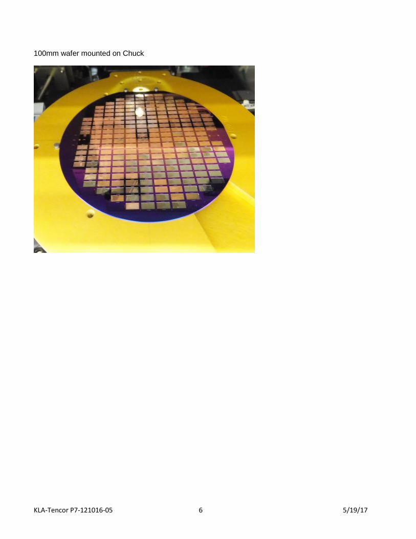
The P-7 has a universal chuck to accommodate wafer and wafer stress applications for either 2, 3, 4, 5 or 6 inch samples. The chuck has a series of holes that accept pins to provide precision alignment of the sample. The pair of holes are used for aligning the wafer flat or for non-flatted wafer, the edge of the sample. The single hole is for aligning the other edge of the sample. To switch between wafer sizes, move the pins between wafer holes.
Wafer Precision Locators:
-in. for Wafer with Flat/Square Substrate
-in. for Wafer with Flat/Square Substrate
-in. for Wafer with Flat/Square Substrate
-in. for Wafer with Notch
-in. for Wafer with Flat/Square Substrate
-in. for Wafer with Notch
-in. for Wafer with Flat/Square Substrate
-in. for Wafer with Notch
WAFER Examples:
3” wafer mounted on Chuck
KLA-Tencor P7-121016-05 6 5/19/17
100mm wafer mounted on Chuck
KLA-Tencor P7-121016-05 7 5/19/17
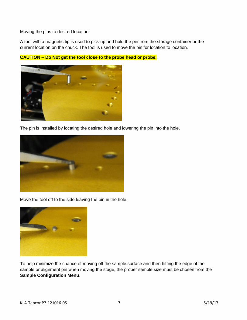
Moving the pins to desired location:
A tool with a magnetic tip is used to pick-up and hold the pin from the storage container or the
current location on the chuck. The tool is used to move the pin for location to location.
CAUTION – Do Not get the tool close to the probe head or probe.
The pin is installed by locating the desired hole and lowering the pin into the hole.
Move the tool off to the side leaving the pin in the hole.
To help minimize the chance of moving off the sample surface and then hitting the edge of the
sample or alignment pin when moving the stage, the proper sample size must be chosen from the
Sample Configuration Menu.

KLA-Tencor P7-121016-05 8 5/19/17
SMALL Samples:
A Small Sample holder is used to locate the small samples on the chuck. It is a glass plate with
references that will be placed on the center of the chuck after your sample has been placed on it.
There will be several holders available and the one to match your sample size must be used. The
glass plate is 50x75mm and will be referenced against three pins on the chuck.
Your sample will be placed on the holder with its edges against the Kapton tape reference edges.
When the chuck is loaded it will be positioned so that the center of the check is at (0,0) in the
coordinate system. This is where the first focus of the sample will take place.
KLA-Tencor P7-121016-05 9 5/19/17
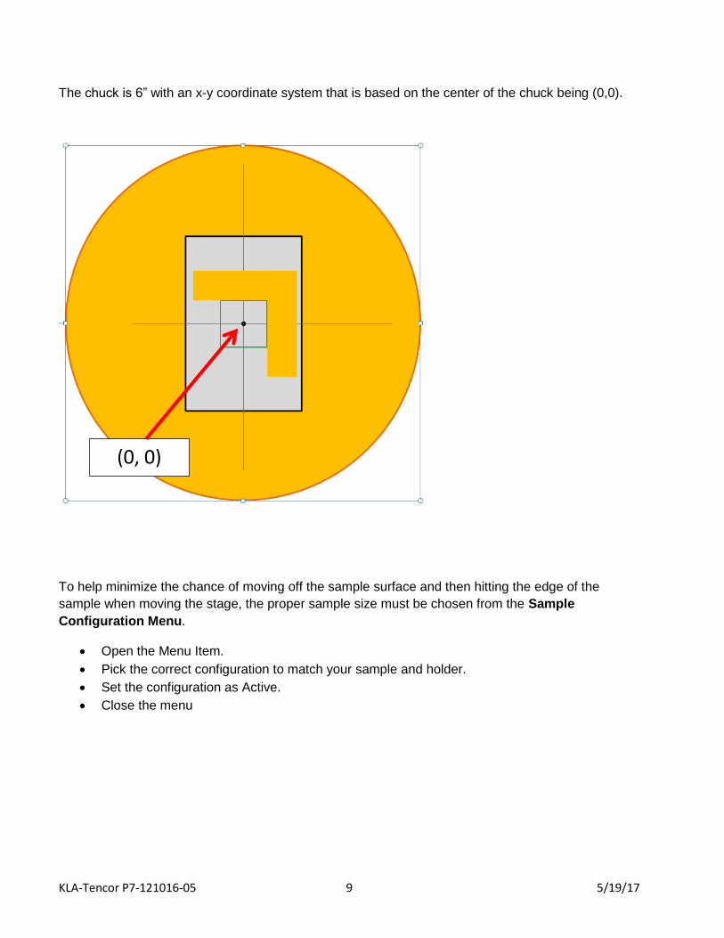
The chuck is 6” with an x-y coordinate system that is based on the center of the chuck being (0,0).
To help minimize the chance of moving off the sample surface and then hitting the edge of the
sample when moving the stage, the proper sample size must be chosen from the Sample
Configuration Menu.
Open the Menu Item.
Pick the correct configuration to match your sample and holder.
Set the configuration as Active.
Close the menu
(0, 0)

KLA-Tencor P7-121016-05 10 5/19/17
A Table of what the options are and how they apply to User’s samples follows.
Menu Option Name Wafer Radius um
Origin (um,um)
X um Y um
WAFER_SIZE_2 2” Waf 25500 0.0
WAFER_SIZE_3 3” Waf 38000 0.0
WAFER_SIZE_4 4” Waf 50500 0.0
WAFER_SIZE_5 5” Waf 63000 0.0
WAFER_SIZE_6 6” Waf 75500 0.0
RECTANGLE_SIZE_1 3x3 mm 0.0 3000 3000
RECTANGLE_SIZE_2 10x10 mm 0,0 10000 10000
RECTANGLE_SIZE_3 20x20 mm 0,0 20000 20000
RECTANGLE_SIZE_4 30x30 mm 0,0 30000 30000
RECTANGLE_SIZE_5 5x5 mm 0,0 5000 5000
Examples of the different
fixtures to match your sample
size:
SIZE_1 (3x3 mm)
and SIZE_3 (20x20 mm)

KLA-Tencor P7-121016-05 11 5/19/17
When you place your sample on the holder or chuck you should orient it so that the feature you want to scan
has edges that are vertical since the scan will be horizontal from left to right.
Your sample must match the size of the fixture and located against the reference edges.
The sample cannot be smaller than the required size or randomly placed on the holder.
The sample can be larger than the intended fixture as long as it can be referenced against the
edges. Only the area of the stated size of the fixture will be available to be scanned so your area of
interest must be in that area.
Example 1 Example 2 Example 3
Example 1) Sample is too small and not against the reference.
DO NOT USE THIS COMBINATION
Example 2) Sample matches the fixture and is against the reference edges.
Example 3) Sample is larger than the scan area and is against the reference edges. Area of sample
outside of the scan area will not be available for measurements.

KLA-Tencor P7-121016-05 12 5/19/17
The Chuck can be rotated about the origin. Normally you would not have to rotate the chuck by 90 degrees.
There is a Fine Theta adjustment for the chuck that should be used for <5 deg adjustments.
When you place your sample on the holder or chuck you should orient it so that the feature you want to scan
has edges that are vertical since the scan will be horizontal from left to right.
A) Normal Load Position (detent at 0 deg.)
B) Rotated to 45 deg. Detent. Do not use this position. It would allow areas to be scanned that are
lower than the sample and off the sample surface. This could result in damage to the scanning tip.
C) Rotated 90 deg. (detent at 90 deg.) Do not use this position if your feature for measurement is
in the scan area and needs to be rotated. The system does not rotated perfectly about (0.0) so the
allowed scan area will not be correct and the tip may be off the sample surface.
A
W
h
e
n
y
o
u
p
l
a
c
e
y
o
u
r
s
a
m
p
l
e
o
B
C
Theta Adjustment: +/- 5 deg.
KLA-Tencor P7-121016-05 13 5/19/17
Measurement Procedure:
Outline
1) Log tool out in CRESS
2) Log on to the P7 tool.
3) Identify the method that will be used to hold your sample for measurement.
4) Open the Recipe Screen and then X-Y Screen
5) Load sample on Chuck and complete the Manual Load.
6) Pick the correct sample configuration for your sample and set it as Active.
7) Focus on Sample
8) Pick the Scan recipe that will be used.
9) Adjust parameters in the recipe.
10) Teach the recipe with your sample.
11) Make measurements
12) Do Measurement Analysis
13) Record results and/or save results.
14) Unload sample.
15) Log Off tool.
16) Log tool back into CRESS.
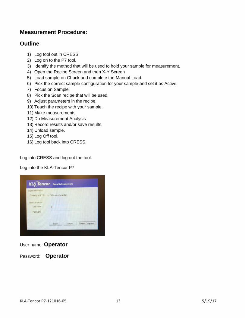
Log into CRESS and log out the tool.
Log into the KLA-Tencor P7
User name: Operator
Password: Operator

KLA-Tencor P7-121016-05 14 5/19/17
When the program starts it open to the Profiler CATALOG Screen:
Highlight the OPERATOR recipes in the Recipe Path:

KLA-Tencor P7-121016-05 15 5/19/17
Open the X-Y Screen:
Open the Sample Configuration and select the correct configuration for
your sample, Set it as Active.
Click on MAN LOAD to load your sample on the chuck:
The stage will move to the door. Open the door and place your sample on the stage in the proper
orientation.
Turn on the vacuum switch located on the inside left edge of the door. Close the door.
Click MAN LOAD to move the stage back under the system head.
KLA-Tencor P7-121016-05 16 5/19/17
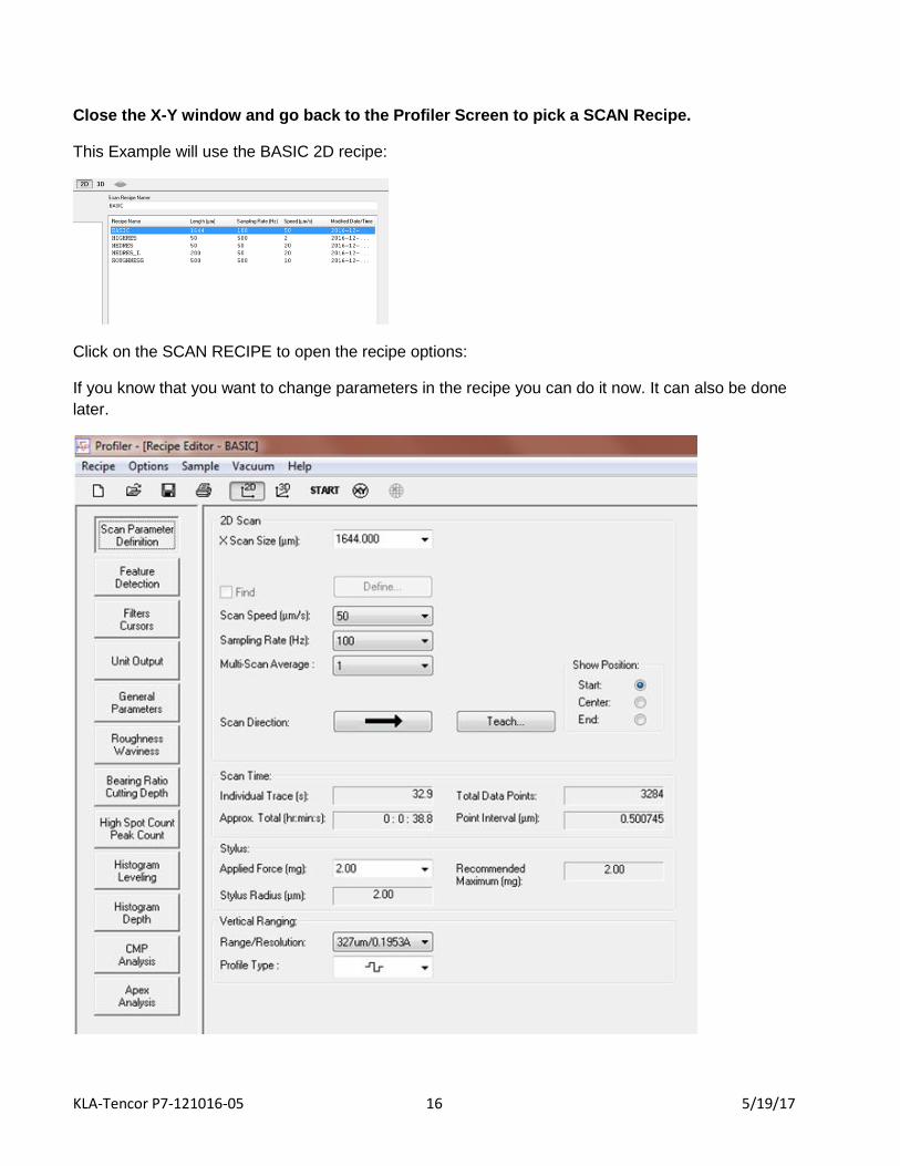
Close the X-Y window and go back to the Profiler Screen to pick a SCAN Recipe.
This Example will use the BASIC 2D recipe:
Click on the SCAN RECIPE to open the recipe options:
If you know that you want to change parameters in the recipe you can do it now. It can also be done
later.
KLA-Tencor P7-121016-05 17 5/19/17
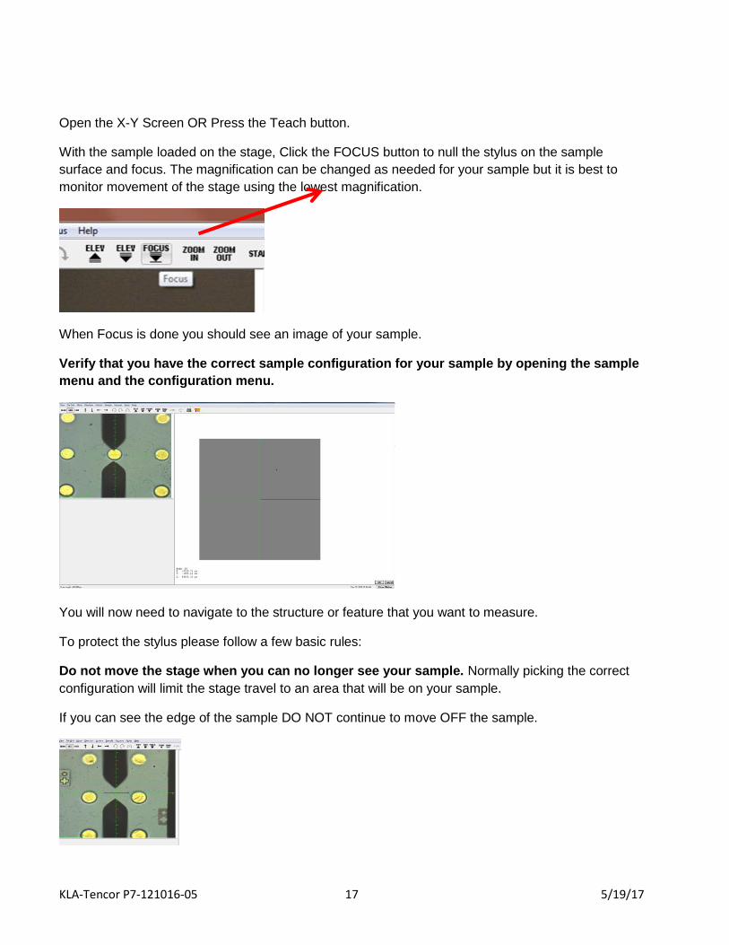
Open the X-Y Screen OR Press the Teach button.
With the sample loaded on the stage, Click the FOCUS button to null the stylus on the sample
surface and focus. The magnification can be changed as needed for your sample but it is best to
monitor movement of the stage using the lowest magnification.
When Focus is done you should see an image of your sample.
Verify that you have the correct sample configuration for your sample by opening the sample
menu and the configuration menu.
You will now need to navigate to the structure or feature that you want to measure.
To protect the stylus please follow a few basic rules:
Do not move the stage when you can no longer see your sample. Normally picking the correct
configuration will limit the stage travel to an area that will be on your sample.
If you can see the edge of the sample DO NOT continue to move OFF the sample.

KLA-Tencor P7-121016-05 18 5/19/17
If you find that you are OFF the sample or do not know where you are on the sample…STOP. Raise
the head up before you move so that the tip does not hit an edge or structure that is too large and
will result in breaking the probe. The easiest way is to reload the sample and start in the loading
position (0, 0).
If you FOCUS when OFF the sample you will have lowered the tip and moving the stage at this time
is likely to break the probe …. STOP. Contact Staff for help.
KLA-Tencor P7-121016-05 19 5/19/17
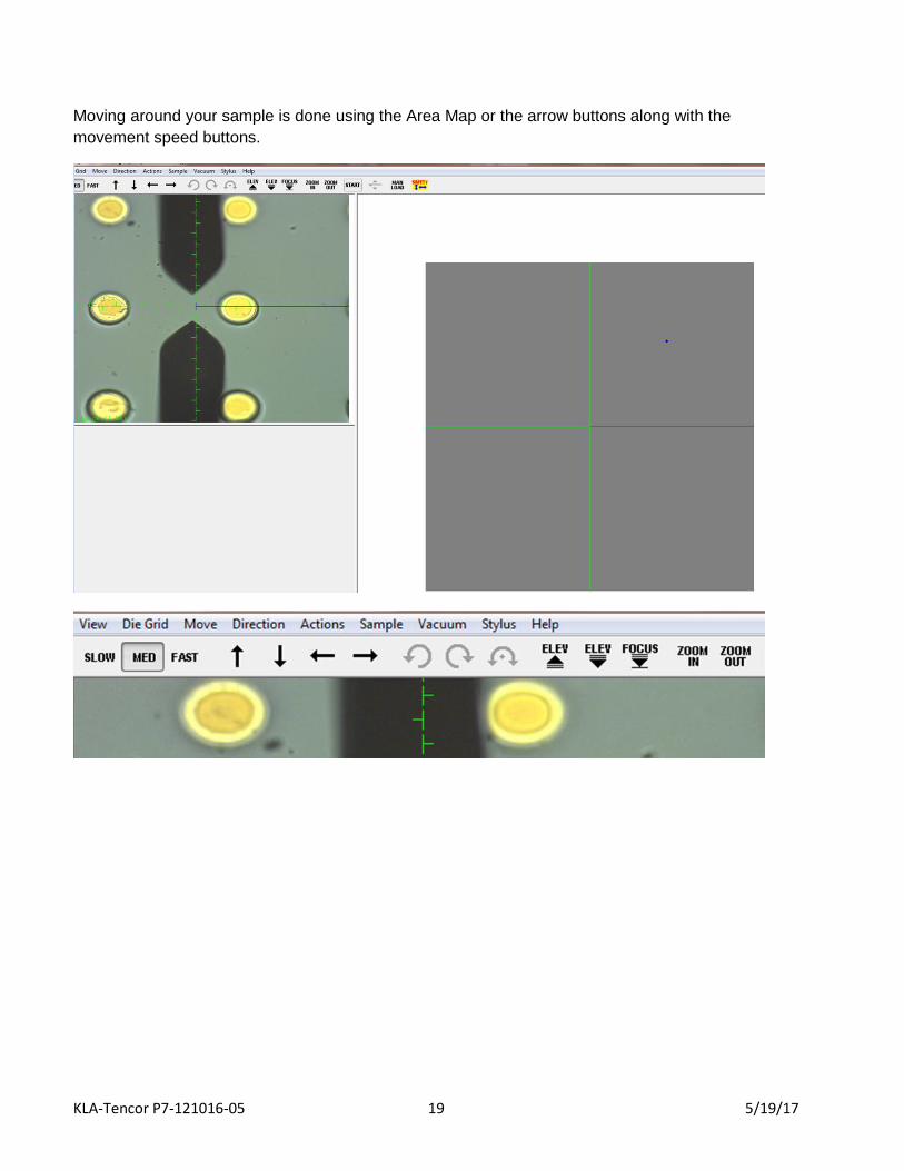
Moving around your sample is done using the Area Map or the arrow buttons along with the
movement speed buttons.

KLA-Tencor P7-121016-05 20 5/19/17
Once you have your structure identified you can set up the scan that you want over the structure of
interest. In this example the blue line represents the scan an it has been set up to scan over two of
the features (right one and blue line is out of the field of view).
Push START and the Scan will begin;
CAUTION – Do not SCAN if you cannot see the device and features you want to measure.
And continue till the scan length is finished.

KLA-Tencor P7-121016-05 21 5/19/17
The finished Scan will be displayed.
The scan can now be leveled using the Level function and moving the cursors over the areas that
you want to level by. When the cursors are in the correct location PRESS the CALC button.

KLA-Tencor P7-121016-05 22 5/19/17
The features can be measured by placing the measurement cursors where you want to make the
measurement. The values based on the cursor positions will be displayed on the left side of the
screen.
When you are done with your measurements Press MANUAL LOAD to move your sample to the
unload position.
Wait for the stage to stop at the door.
Open the door.
Turn of the vacuum to the stage.
Remove your sample.
Close the door.
Close the X-Y window.
Close the Recipe window and do not save your recipe parameters. If you want the setup to be added
as a recipe, contact the staff to help do this.

KLA-Tencor P7-121016-05 23 5/19/17
Logging OFF the tool as an Operator:
On the Catalog Screen, OPEN “File” and PICK “Logoff” from the menue
Clean up the area as needed.
Log off the tool in CRESS.

KLA-Tencor P7-121016-05 24 5/19/17
Recipe Parameters:

KLA-Tencor P7-121016-05 25 5/19/17

KLA-Tencor P7-121016-05 26 5/19/17

KLA-Tencor P7-121016-05 27 5/19/17

KLA-Tencor P7-121016-05 28 5/19/17
KLA-Tencor P7-121016-05 29 5/19/17

KLA-Tencor P7-121016-05 30 5/19/17
KLA-Tencor P7-121016-05 31 5/19/17

KLA-Tencor P7-121016-05 32 5/19/17
KLA-Tencor P7-121016-05 33 5/19/17

KLA-Tencor P7-121016-05 34 5/19/17