knowledge-based support in non-destructive testing for
TRANSCRIPT

HAL Id: hal-00831141https://hal.archives-ouvertes.fr/hal-00831141
Submitted on 6 Jun 2013
HAL is a multi-disciplinary open accessarchive for the deposit and dissemination of sci-entific research documents, whether they are pub-lished or not. The documents may come fromteaching and research institutions in France orabroad, or from public or private research centers.
L’archive ouverte pluridisciplinaire HAL, estdestinée au dépôt et à la diffusion de documentsscientifiques de niveau recherche, publiés ou non,émanant des établissements d’enseignement et derecherche français ou étrangers, des laboratoirespublics ou privés.
Knowledge-based support in Non-Destructive Testingfor health monitoring of aircraft structures
Bernard Kamsu-Foguem
To cite this version:Bernard Kamsu-Foguem. Knowledge-based support in Non-Destructive Testing for health monitor-ing of aircraft structures. Advanced Engineering Informatics, Elsevier, 2012, vol. 26, pp. 859-869.�10.1016/j.aei.2012.06.006�. �hal-00831141�

Any correspondence concerning this service should be sent to the repository administrator: [email protected]
To link to this article: DOI:10.1016/j.aei.2012.06.006 http://dx.doi.org/10.1016/j.aei.2012.06.006
This is an author-deposited version published in: http://oatao.univ-toulouse.fr/ Eprints ID: 8840
To cite this version: Kamsu Foguem, Bernard Knowledge-based support in Non-Destructive Testing for health monitoring of aircraft structures. (2012) Advanced Engineering Informatics, vol. 26 (n° 4). pp. 859-869. ISSN 1474-0346
Open Archive Toulouse Archive Ouverte (OATAO) OATAO is an open access repository that collects the work of Toulouse researchers and makes it freely available over the web where possible.

Knowledge-based support in Non-Destructive Testing for health monitoringof aircraft structuresq
Bernard Kamsu-Foguem ⇑
Laboratory of Production Engineering (LGP), EA 1905, ENIT, INPT, University of Toulouse, 47 avenue d’Azereix, BP 1629, 65016 Tarbes Cedex, France
Keywords:
Experienced knowledge
Formal visual reasoning
Conceptual graphs
Non-Destructive Testing
Maintenance procedure
Aircraft industry
a b s t r a c t
Maintenance manuals include general methods and procedures for industrial maintenance and they con-
tain information about principles of maintenance methods. Particularly, Non-Destructive Testing (NDT)
methods are important for the detection of aeronautical defects and they can be used for various kinds
of material and in different environments. Conventional non-destructive evaluation inspections are done
at periodic maintenance checks. Usually, the list of tools used in a maintenance program is simply located
in the introduction of manuals, without any precision as regards to their characteristics, except for a short
description of the manufacturer and tasks in which they are employed. Improving the identification con-
cepts of the maintenance tools is needed to manage the set of equipments and establish a system of
equivalence: it is necessary to have a consistent maintenance conceptualization, flexible enough to fit
all current equipment, but also all those likely to be added/used in the future. Our contribution is related
to the formal specification of the system of functional equivalences that can facilitate the maintenance
activities with means to determine whether a tool can be substituted for another by observing their
key parameters in the identified characteristics. Reasoning mechanisms of conceptual graphs constitute
the baseline elements to measure the fit or unfit between an equipment model and a maintenance activ-
ity model. Graph operations are used for processing answers to a query and this graph-based approach to
the search method is in-line with the logical view of information retrieval. The methodology described
supports knowledge formalization and capitalization of experienced NDT practitioners. As a result, it
enables the selection of a NDT technique and outlines its capabilities with acceptable alternatives.
1. Introduction
Certification authorities require that exposed aircraft compo-nents must be tested to prove their impact-resistant structure.The destructive and semi destructive methods (e.g. sectioning, con-tour, hole-drilling, ring-core and deep-hole) rely on the measure-ment of parameters (e.g. deformations) due to the release ofactions (e.g. residual stresses) upon removal of material from thespecimen. The non-destructive methods (e.g. X-ray, ultrasonicand magnetic methods) typically measure some parameters thatare related to the assessment of component-inspected damage,without removing material [1]. Non-Destructive Testing (NDT)methods for assessing the integrity of an aircraft structure areessential to both improve reliability and availability of aircraftdue to maintenance [2]. NDT techniques provide fitting inspectionand evaluation means that can be used to monitor the complianceof airworthiness requirements for civil aircraft structures [3]. Theyfor the assessment of fatigue related damage become increasingly
significant, since many structural components need to be inspectedperiodically to prevent major damage or even failure [4]. Thesetechniques usually measure some parameters that are related tothe stress, in order to detect service failures in aircraft components,which occur by fatigue [5]. Predominantly, a key concern with age-ing aircraft is the deterioration of structural components in theform of fatigue cracks at fastener holes, loose rivets and disbondingof joints [6]. The failures are revealed during regular control by themaintenance unit for non-destructive examination. The mainte-nance service aims to define the methods of maintenance of equip-ment in an ongoing effort to improve the quality and cost. Amongother things, they must address the demands of the workshop(document changes such as Component Maintenance Manual(CMM)/Equipment Maintenance Manual), to improve methodsand processes. CMM is a document issued by the manufacturerof the equipment, which allows for the complete maintenance ofthe equipment. Maintenance operations in aeronautics aim toguarantee the aircraft performance, its availability and airworthi-ness. Particularly, these operations can identify the locations andreasons for failure during high energy impact to simple aircraftstructures. In order to improve maintenance processes, it can beused to create parts lists that will belong to the kits (parts list to
q Handled by C.-H. Chen⇑ Tel.: +33 6 24 30 23 37; fax: +33 5 62 44 27 08.
E-mail address: [email protected]

resolve technical problems) based on equipment failure. Theimplementation of these kits is useful for improving common tem-plates in the industrial maintenance. To enable this development,the creation of electronic records management is required. Appro-priate identification of aircraft maintenance equipments is a chal-lenge, as aircraft configurations change depending on assignmentsand maintenance procedures. Aeronautical maintenance reliesupon a multifaceted system based on functional and safetyrequirements, test methods and continuous improvement. Supportcontracts imply certain collaborations between customer premises,supplier OEM (Original Equipment Manufacturer) and subsidiariespremises. This maintenance can be carried out from the simple le-vel to a more complex level [7]. At the simple maintenance level,actions require either simple procedures or the use of easily em-ployed maintenance equipment. This type of action is performedby qualified personnel following the detailed procedures and usingthe equipment specified in the maintenance instructions (e.g.checking parameters on a piece in use, simple adjustments (align-ment, change of settings, etc.)). At the complex maintenance level,activities require the know-how based on the mastery of highlyspecialized techniques or technologies. By definition, this type ofmaintenance operation (overhaul, reconstruction, etc.) is carriedout by the manufacturer or by a specialized service or companyfamiliar with the manufacture of the equipment and using mainte-nance equipment defined by the manufacturer (e.g. general over-haul with complete dismantling of the engine, dimensional andgeometric repair, major repairs or restoration carried out by themanufacturer, etc.).
In this paper, we discuss how formal semantics representationscan be applied profitably to tackle the problems of formal specifica-tion of technical resources of maintenance procedures with visualreasoning mechanisms in industrial maintenance management.As an application example, we focus on a formal conceptual model-ling of technical resources used in maintenance procedures of Non-Destructive Testing in aircraft industry applications.
The paper is organized as follows: Section 2 presents a literaturereview about Non-Destructive Testing methods for aircraft struc-tures and introduces the principles of information structuring formaintenance equipments. The conceptual graphs formalism used
throughout our work is detailed (formal semantics and reasoningconstructs) in Section 3. Section 4 states how to apply the formal-ization approach in the context of equipments management forNon-Destructive Testing procedures in aircraft industry applica-tions. Section 5 presents concluding remarks about the proposedapproach to improve domain knowledge formalization from con-ceptual modelling to requirements specification.
2. Information management in structural health monitoring
2.1. State-of-the art Non-Destructive Testing methods
Failures of different aircraft components are revealed andexamined generally by the use of non-destructive examinationmethods. The NDT methods can reliably detect and locate defectshaving dimensions well below those, which could impair the ther-mal fatigue lifetime. For instance, Non-Destructive Testing (NDT)methods that visualize the propagation of ultrasonic waves insolids are applicable to inspections of composite structures fordisbonding detections [8]. These methods are also applied to detectfretting damage on the faying surfaces of intact specimensrepresenting aircraft fuselage joint construction [9].
We chose to create a hierarchy of domain concepts, establishinga tree with four levels, from general to specific. The idea is to en-sure that equipment has a unique code, while a code may containseveral pieces of equipment (see Fig. 1). For example, EPH-GDAE:Eddy Current Probe for High Frequency Eddy Current and Use Stan-dard/ Geometry 45° + Angle Tip-Shielded/ Frequency 500kHz.
2.1.1. First-conceptual description: General methods
For instance, ultrasonic inspection of materials offers interest-ing possibilities for the development of in-line Non-DestructiveTesting (NDT) systems. Depending on the configuration, one ormore ultrasonic images of the defect can be observed, their num-ber and relative position containing information about the locationof the defect. More commonly, these methods are eight in number:
� Visual inspection.� Optical methods.
Fig. 1. An example of equipment codification (courtesy of Airbus S.A.S).

� Eddy-current (electro-magnetic testing).� Ultrasonic inspection (including Laser ultrasonics).� Acoustic emission.� Vibration analysis.� Radiography.� Thermography.
These methods are effective to evaluate various defects and/orsubsurface features on aerospace composites and aircraft metallicstructures. They have been used in a variety of applications, i.e.inspection of subsurface defects and features, identification ofthermo-physical properties, detection of coating thickness and hid-den structures. We are inspired by the review found in [4] for adescription of currently used NDT methods as follows:
Visual inspection confines itself to the detection of flaws locatedproximate to the surface. The techniques of impact sensitive coat-ings, liquid penetrants and magnetic particles are used to enhancethe sensitivity and resolution of the inspection.
Optical methods contain photoelasticity, holography, Shearogra-phy and Moire methods that recognize material changes based onvariations in transmission intensities, and phase changes, diffrac-tion properties and interference fringe patterns. In particular, Shea-rography has advantages in terms of the large area testingcapabilities (up to 1 m2 per minute), the non-contact properties,the insensitivity to environmental disturbances, and the good per-formance on honeycomb materials.
Eddy current testing is an electromagnetic method carried out asa routine depot maintenance procedure to examine the conditionof the structures for surface and around surface cracks, corrosion,delaminations and other structural defects (e.g., the state of the in-ner wing weep holes). Of course, it is advisable that such a smarteddy current NDT system is complemented by strictly optimizedmachine settings including finite element method for analysis ofthe inductive field caused by the eddy current sensor [10].
Ultrasonic inspection employs concentrated high energy acousticwaves to pinpoint flaw existence and flaw dimensions, determinegeometric dimensions and characterize material properties. Appli-cations include impact damage detection and location in compos-ite beams and Crack Detection in repaired metallic structures. Also,it is applied to detect fatigue damage in carbon-fibre-reinforcedepoxy (CFRP) composites used in aircraft structures. Laser ultra-
sonic offers the flexibility of testing structures with complex curva-tures as the probe does not have to be normal to the surface.
Acoustic emission (AE) detects movement of defects in solids(e.g. fibre breakage, matrix cracking and delamination (disbondingof neighbouring plies)). Also, AE can inspect impact damage andstudy the fracture behaviour of composite materials. In AE, Lamwaves are considered as a means of detecting active flaws andassessing damage (and other material attributes) distributed oversubstantial areas. Lamb wave based scanning methods are engagedto distinguish internal damage in multi-layered compositesstructures.
Vibration based methods (e.g. Coin-tap) are effective for qualitycontrol of filament wound carbon fibre reinforced plastic (CFRP)tubes and detection of production defects such as incorrect wind-ing angle or wrong ply orientation.
Radiographic inspection is interesting in industrial applicationsfor isotropic material. For instance, an X-ray photograph can illus-trate damage (e.g. cracking, splitting and delamination) in a multi-directional carbon fibre/ epoxy laminate loaded in compression–compression fatigue.
Thermography methods (e.g., lock-in thermography, pulse ther-mography or vibro-thermography) are useful to detect delamina-tions, corrosions, surface cracks and voids. Besides, they arerelevant to honeycomb constructions and thermoplastic compositewelds.
2.1.2. Second conceptual description: Equipment family
The second level of description is the type of study tool: mea-suring instrument, probe, calibration block, etc. Some tools areonly available for a very precise method. This is for example thecase of Hammer, which is used exclusively for the resonance meth-od, or the Tube for X-ray method. Here is an example of ultrasonicmethods in terms of the parameter family.
� Instrument.� Search unit.� Reference.� Cable.� Miscellaneous.� Wedge.� Encoder.� Program.
2.1.3. Third conceptual description: Specific techniques
Specific techniques can vary according to the general method. Itis clear that the endoscopic technique is specific to a visual test,and can never be found in the thermography method. For example,here are the specific techniques of the Eddy Current Method. How-ever, there are some exceptions, such that the Thickness Measure-ment exists both in Eddy Currents and in Ultrasonic methods. Wecan found these following specific techniques:
� Conductivity Measurement.� Thickness Measurement.� Eddy Current Array.� Low Frequency Eddy Current (LFEC).� High Frequency Eddy Current (HFEC).� Rototest.
2.1.4. Fourth conceptual description: Dimensional parameters
The dimensional parameters depend on all business parametersand therefore vary according to their respective specificities: thedimensional parameters for an ultrasonic probe are not the sameas those of an eddy current probe, also those of an ultrasonic probeare not the same as those of an ultrasonic analysis instrument.
They can also differentiate two equipments used for the sametype of control hence identify the most suitable.
For an ultrasonic probe, these parameters are for example:
� Diameter.� Frequency.� Length.� Thickness.� Depth/Angle.
The conceptual descriptions (e.g. General methods, Equipmentfamily, Specific techniques and Dimensional parameters) cannotonly be used for NDT of aircraft structure but also used for otherstructures, such as in refineries, chemical plants and power plants.For example, the principal industrial uses of magnetic particleinspection are final inspection, receiving inspection, in processinspection and quality control, maintenance and overhaul in thetransportation industries (truck, railroad, and aircraft), plant andmachinery maintenance, and inspection of large components.However, this research work is conducted to meet the needs of amajor Aircraft Company located in our industrial environment,while proposing high added value maintenance expertise for itsCustomer Support Structure Engineering. In particular, Aircraftcomponents such as aluminum structural parts, titanium engineblades, and metallic composite materials can be readily inspectedusing eddy current inspection techniques. More generally, NDTinspections have been successful in detecting early cracking and

in accelerating corrective actions. Additionally, the integrity ofmany high performance components in gas turbine engines is crit-ical to aircraft safety. Therefore, management procedures (such asindividual engine tracking procedures and realistic inspection andmaintenance requirements) must be defined and enforced.
2.2. Information structuring for maintenance equipment’s
representation
Industrial information systems manipulate and manage largevolumes of information that need to be carefully represented andunderstood in order to generate useful knowledge from the datamodels. Habitually, Entity–Relationship–Attribute (ERA) modellingor object-oriented modelling (defining class and object hierarchies)are used as data modelling methods [11]. Such methods employdifferent representation formalisms and codification techniquesthat are implemented in industrial frameworks for informationstructuring with a database query processing. However, equipmentcodifications mean distinct things in different applications, sincethey do not have to have a shared semantics to be comparableacross sources. In addition, when there are many changes in thecatalogues of manufacturers, their nomenclatures can becomeincreasingly complex or even opaque in some extreme cases. Thishappens for example when a supplier has subsequently acquirednew companies, purchased stakes in other companies, and madesome divestments; or when changing policy on the classificationof different manufacturers (e.g. the transition from a technical codeto an incremental code). So, a high codification system is funda-mental to serve as a means for equipments utilization research inorder to improve quality of maintenance equipments use. Onecomponent of this is the presentation and comparison of mainte-nance equipment characteristics with possible substitutions atinternational and other levels. Statistics show that a vast majorityof industrial maintenance equipments can be replaced by elementswith the same characteristics. In practical facts, in only a very smallnumber of cases, maintenance teams must mandatory use thesame tool described in the development of procedures. Therefore,it is essential to work on a semantic conceptual identification toknow the equivalent equipments according with a defined specifi-cation. In this context, ontology is an enabling approach thatexplicitly specifies intended meanings of the conceptualizations(e.g. centralised or distributed categorization) for informationsharing and manipulation [12]. Nowadays, ontologies are designedto improve the accuracy of search engines and enable an interop-erable communication at the semantic level [13]. The engagementof a coherent ontology is valuable because maintenance supportsystems’ users can reason about the semantic differences or iden-tities among the vocabulary used in several and independentlydeveloped databases [14]. In this perspective it is opportune toprovide the construction of a hierarchical conceptual structurewith a formal support having an underlying logical description.Such that when linked to existing information systems, the hierar-chical conceptual structure of domain knowledge can support botha broader overview and some deep analysis. For instance, by inves-tigating on groups of technical equipments with similar functionaland behavioural properties, it is possible to find out if there areequivalent alternative equipments that can be used in a targetmaintenance procedure [15]. The maintainer should be promptedfor the location of the alternative equipments with informationstructuring that provides ways for managing, reappraising, andreusing alternative equivalents for NDT objects. Maintenanceequipments are classified according to the main testing/inspec-tion/evaluation use of the main effective characteristics; on the ba-sic principle of only one NDT equipment code for each route ofmanagement (i.e. preventive/curative forms with similar charac-teristics and strength will have the same NDT equipment code).
To identify some common conceptualization of the data, our ap-proach includes the following steps:
� Analysis of equipments was an essential step. For the developmentof our work. Indeed, it is from this analysis and research thatkey parameters of the equipment, are associated to mainte-nance equipment’s codifications. This consists of referencingthe equipments of all programs, and studying the proceedingsin which they were called to determine which characteristicswere important for the performance of maintenance testing. Itappeared that three types of parameters were to remember:three parameters of business on the field use of the tool, threedimensional parameters, and three parameters of effectiveness.� The next step was the development of the equipment code from
these key parameters. Initially, we were directed towards a 3-part code (one for each type of parameters), but then it was con-sidered more suitable to use a 2-part code, because the param-eters of effectiveness were not really useful in the code. The firstpart is to say, business settings, is mnemonic, which identifiesquickly what tool we have to deal with, while the dimensionalpart is incremental, because it would be impossible to keep thecode short and constant length if it was also mnemonic.
Codifying equipments’ identification offers a thought-provokingframe into the intersection of semi structured data with context-dependent semantics (tags and alignments of reference numbersmeaning, equipment’s online characteristics) and formal reasoning(logical inference, database query processing, or constraint satis-faction method).
The research work presented in this paper is intended to exam-ine whether maintenance experts-as-users can represent domainvocabulary structuring better using conceptual graphs. So, the pro-posal of conceptual graphs for formal representation of equip-ments is motivated by communication, information structuringand formal reasoning requirements viewpoints [16,17]. This paperfurther describes how the suggested approach is appropriate tosupport formal analysis and to represent graphically knowledge,logic and concepts used in equipment descriptions. The work isdone with the intention to render equipment descriptions moreuser-friendly using conceptual graphs that can improve the read-ability of the reasoning services in its diagrammatic form. Main-tainers-as-users would interpret better the selection of theneeded equipment based on procedures’ recommendations thatis represented formally by knowledge conceptualization principleswith associated knowledge reasoning techniques.
3. Graph-based knowledge representation and reasoning
Our choice for knowledge modelling is oriented towards theconceptual graphs formalism [18]. Indeed, on the one hand, it al-lows the formalization of conceptual and procedural knowledgeof a target domain; on the other hand, the provided reasoning toolsfacilitate the visualization, the enrichment and the verification ofthe modelled knowledge by end users [19]. Furthermore, there isa formal correspondence between conceptual graphs and Descrip-tion Logics that is the most implemented language in variousknowledge base applications. Also, there are many mappings be-tween conceptual graphs and languages associated to semanticweb applications [20,21] (RDF(s) (Resource Description Frame-work), DAM-OIL (DARPA Agent Markup Language), OWL-DL(Web Ontology Language-Description Logics) or Topic Maps)).
3.1. Conceptual graphs as a formal visual modelling language
The appropriate processing of maintenance knowledge requiresthe use of a knowledge representation language having a well-de-

fined syntax and a formal semantics. The conceptual graph (CG)formalism [16] can be considered as a compromise representationbetween a formal language and a graphical language as it is visualand has a range of reasoning processes. Visual languages carrygreat symbolic meaning in human cultures and range from infor-mal ambiguous sketches to rigorously defined technical diagrams.They have become a key component of human-computer interac-tion. Conceptual graphs operations provide formal reasoning toolsthat allow ensuring reliability and enhance the quality of mainte-nance knowledge-based systems. These are critical factors for theirsuccessful use in real-world applications. For instance, these rea-soning tools can help the user to determine whether a knowl-edge-based system does or does not satisfy its purely formalspecifications [22].
3.1.1. Basic definitions
A simple conceptual graph is a finite, connected, directed, bipar-tite graph consisting of concept nodes (denoted as boxes), whichare connected with conceptual relation nodes (denoted as circles).In the alternative linear notation, concept nodes are written within[]-brackets while conceptual relation nodes are denoted within ()-brackets [23].
A concept is composed of a type and a marker [<type>:<mar-ker>], for example [Equipment: Ultrasonic Probe75]. The type ofconcept represents the occurrence of object class. They are groupedin a hierarchical structure called a concept lattice showing theirinheritance relationships. The marker specifies the meaning of aconcept by specifying an occurrence of the type of concept. Theycan be of various natures, in particular: individual, generic (symbol‘�’ within the marker), quantifiers or sets (the latter by using {}-brackets within the marker).
A conceptual relation binds two or more concepts according tothe following diagram [C1] (relation’s name) [C2] (means ‘C1
is in relation with C2’). Each relation has a signature, which fixesits arity (the number of arguments it takes) and gives the maxi-mum types of concept available, to which a relation of the typecan relate. In particular, a singular evolves into relation capturesthe notion of transformation over time [24]. The sub-relation def-inition is sometimes necessary to provide more details in thesemantic representation, and then a relation lattice is established.
3.1.2. Formal semantics
Conceptual graphs are provided with semantics in first-order-logic, defined by a mathematical mapping classically denoted byU [16]. This shows how the symbols of conceptual graphs theorymap into corresponding quantities in logic theory, transformingthe axioms of its domain into axioms or theorems of first-order-lo-gic. Concept types are translated into unary predicates and rela-tions into predicates of the same arity. Individual markersbecome constants. To a vocabulary V is assigned a set of formulasU(V) which translates the partial orders on concept types and rela-tions: if t and t0 are concept types, with t0 < t, one has the formula"x (t0(x)? t(x)); similarly, if r and r0 are n-ary relations, withr0 < r, one has the formula "x1 . . . xn (r0(x1 . . . xn)? r(x1 . . . xn)).
3.1.3. Reasoning through graph homomorphism
In mathematics, a homomorphism is an abstraction derivedfrom structure-preserving mappings between two mathematicalstructures [25]. It is a process that combines a set in another, whilepreserving all the information on the structure of the first set in thesecond set. Indeed, in many cases, the useful properties of an objectwill be shared by all objects isomorphic in a bijective map (one-to-one correspondence). In the mathematical field of graph theory agraph homomorphism is a mapping between two graphs that re-spects their structure [26]. More concretely it maps adjacent verti-ces to adjacent vertices. A given function from G to H is a graph
morphism if the image of every edge of G is an edge of H. If thereis a morphism of G into H, we say that classically G ‘‘projects’’ in H(i.e. subgraph matching). In fact, the projection operation is a com-putational task in which two graphs G and H are given as input,and one must determine whether H contains a subgraph that is aspecialization of G. However, its running time is in general expo-nential, for numerous special classes of graphs (e.g. Trees, Planargraphs, Permutation graphs), the graph isomorphism problem havepolynomial-time algorithms, and in practice it can habitually besolved efficiently [27]. It has been showed that the query evalua-tion and query containment problems of relational structuresand databases are equivalent to CG homomorphism problem, inthe case of conjunctive, positive and non-recursive queries [23].
3.2. The use of conceptual graphs in NDT
Conceptual graphs are used to express and process maintenanceknowledge of text equipment descriptions. The domain vocabularyof the target maintenance domain (procedures of Non-DestructiveTesting in aircraft industry applications) is formalized. This vocab-ulary layer supports the evolution of vocabularies as it can definerelations between the different concepts and expresses a commu-nity’s consensus knowledge about a domain. Graph operationsfacilitate how to use the reasoning mechanisms in order to facili-tate formal descriptions representation of the maintenance proce-dures. The purpose is to allow the maintenance domain expert (1)to specify the conceptual vocabulary of the domain by using con-cepts and relationships between these concepts, (2) to specifythe axioms and properties of the domain in a graphical way and(3) to make these axioms easily operational in order to performreasoning with conceptual graph formalism in the context ofNon-Destructive Testing in aircraft industry applications.
The interest of creating an explicit conceptual modeling is toguide equipment and method selection for NDT management,since a structured syntax and a fixed domain vocabulary reducethe task of semantic interpretation processing significantly [28]:
� The conceptualization of domain vocabulary with a formaldescription that would be at an abstraction level potentiallyindependent of changes in manufacturers’ catalogues.� The specification of operational knowledge by using this con-ceptualization would greatly facilitate the establishment ofequivalences between maintenance devices, thereby reducingthe delays and costs to organizations and their customers.
We are interested in the following issue: How to provide a for-mal model to consolidate multiple components correspondencesand annotate their description/documentation to allow a rapiddecision making in an industrial maintenance centre. Many the-sauri are managed jointly on different groups of products. This for-mal model will be used to uniquely identify any equipments withthe NDT method, to index their associated documentation, and tofacilitate the semantic search with further explanations.
3.2.1. Ontological domain vocabulary modelling
An ontology model as a clear specification has three roles [29].
- To represent key concepts and relations of the modellingdomain in a structural way in order to supply maintenanceusers clearly understand conceptual domain knowledge.
- To facilitate communication between various domain actorsand software tools with a formal semantic conceptualizationproviding knowledge sharing for problem solving and decisionsupport assistances.
- To serve as a basis for reasoning, since verification (via the pro-jection operation) is essentially based on the father-son rela-
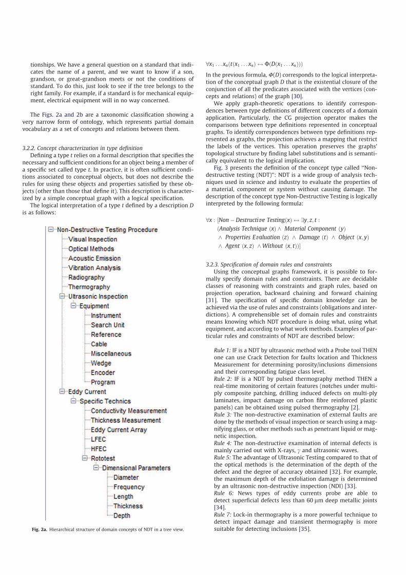
tionships. We have a general question on a standard that indi-cates the name of a parent, and we want to know if a son,grandson, or great-grandson meets or not the conditions ofstandard. To do this, just look to see if the tree belongs to theright family. For example, if a standard is for mechanical equip-ment, electrical equipment will in no way concerned.
The Figs. 2a and 2b are a taxonomic classification showing avery narrow form of ontology, which represents partial domainvocabulary as a set of concepts and relations between them.
3.2.2. Concept characterization in type definition
Defining a type t relies on a formal description that specifies thenecessary and sufficient conditions for an object being a member ofa specific set called type t. In practice, it is often sufficient condi-tions associated to conceptual objects, but does not describe therules for using these objects and properties satisfied by these ob-jects (other than those that define it). This description is character-ized by a simple conceptual graph with a logical specification.
The logical interpretation of a type t defined by a description D
is as follows:
8x1 . . . xnðtðx1 . . . xnÞ $ UðDðx1 . . . xnÞÞÞ
In the previous formula, U(D) corresponds to the logical interpreta-tion of the conceptual graph D that is the existential closure of theconjunction of all the predicates associated with the vertices (con-cepts and relations) of the graph [30].
We apply graph-theoretic operations to identify correspon-dences between type definitions of different concepts of a domainapplication. Particularly, the CG projection operator makes thecomparisons between type definitions represented in conceptualgraphs. To identify correspondences between type definitions rep-resented as graphs, the projection achieves a mapping that restrictthe labels of the vertices. This operation preserves the graphs’topological structure by finding label substitutions and is semanti-cally equivalent to the logical implication.
Fig. 3 presents the definition of the concept type called ‘‘Non-destructive testing (NDT)’’: NDT is a wide group of analysis tech-niques used in science and industry to evaluate the properties ofa material, component or system without causing damage. Thedescription of the concept type Non-Destructive Testing is logicallyinterpreted by the following formula:
8x : ½Nonÿ Destructive TestingðxÞ $ 9y; z; t :
ðAnalysis Technique ðxÞ ^ Material Component ðyÞ
^ Properties Evaluation ðzÞ ^ Damage ðtÞ ^ Object ðx; yÞ
^ Agent ðx; zÞ ^Without ðx; tÞÞ�
3.2.3. Specification of domain rules and constraints
Using the conceptual graphs framework, it is possible to for-mally specify domain rules and constraints. There are decidableclasses of reasoning with constraints and graph rules, based onprojection operation, backward chaining and forward chaining[31]. The specification of specific domain knowledge can beachieved via the use of rules and constraints (obligations and inter-dictions). A comprehensible set of domain rules and constraintsmeans knowing which NDT procedure is doing what, using whatequipment, and according to what work methods. Examples of par-ticular rules and constraints of NDT are described below:
Rule 1: IF is a NDT by ultrasonic method with a Probe tool THENone can use Crack Detection for faults location and ThicknessMeasurement for determining porosity/inclusions dimensionsand their corresponding fatigue class level.Rule 2: IF is a NDT by pulsed thermography method THEN areal-time monitoring of certain features (notches under multi-ply composite patching, drilling induced defects on multi-plylaminates, impact damage on carbon fibre reinforced plasticpanels) can be obtained using pulsed thermography [2].Rule 3: The non-destructive examination of external faults aredone by the methods of visual inspection or search using a mag-nifying glass, or other methods such as penetrant liquid or mag-netic inspection.Rule 4: The non-destructive examination of internal defects ismainly carried out with X-rays, c and ultrasonic waves.Rule 5: The advantage of Ultrasonic Testing compared to that ofthe optical methods is the determination of the depth of thedefect and the degree of accuracy obtained [32]. For example,the maximum depth of the exfoliation damage is determinedby an ultrasonic non-destructive inspection (NDI) [33].Rule 6: News types of eddy currents probe are able todetect superficial defects less than 60 lm deep metallic joints[34].Rule 7: Lock-in thermography is a more powerful technique todetect impact damage and transient thermography is moresuitable for detecting inclusions [35].Fig. 2a. Hierarchical structure of domain concepts of NDT in a tree view.

Rule 8: Spring loaded probes are excellent for situations whereconstant tip-to-surface angle and pressure is required. Theseprobes are typically used for part sampling and corrosiondetection.Constraint 1: Endoscopic technique is specific to a visual test,and can never be in the thermography method.Constraint 2: The composite parts of low ductility should not beassessed for thermography.Constraint 3: Small defects, like cavities or internal microcracksin a metal component, can have serious consequences on thereliability of a mechanical part.Constraint 4: Each of NDT method possesses it specificities pre-destining it to some types of procedures associated to mechan-ical or structural element of the aircraft.Constraint 5: Relevant information concerning the defects canonly be obtained both quickly and precisely, by the selectionof several NDT methods having complementary detection capa-bilities. For example, ultrasonic, Shearography and Infraredthermography methods can be used together to provide activestructural health monitoring and to ensure the fast time of con-trol and a good estimation of typical flaws: disbonds, delamin-ations, wrinkles, porosity, foreign objects and impact damages[32].
The characteristics of the material that may affect NDT methodselection are highly dependent on the specific NDT activity under
consideration. The Table 1 describes some NDT methods and theirimportant characteristics. Besides, NDT methods having comple-mentary inspection/detection/evaluation capabilities can be usedwith various kinds of material and in various types of environmentfor fault/damage monitoring.
The above rules and constraints can be formalized to providethe intelligible analysis that establishes the formal specificationof maintenance procedure. More formally, rules and constraintscan be represented by some logical predicates that are straightfor-wardly link to the conceptual graphs with the expressiveness of vi-sual communication to induce creative problem solving [30].
Fig. 2b. Hierarchical structure of domain concepts of NDT in a graph view.
⇔Non-Destructive Testing (x)
Object
Product : xAnalysis Technique : *x
Without
Agent
Product : xMaterial Component: *
Product : xDamage: *
Product : xProperties Evaluation: *
definition
Fig. 3. Definition of the concept type ‘‘Non-Destructive Testing’’.
Table 1
NDT methods and their important material characteristics.
NDT method Characteristic
Liquid penetrant Flaw must intercept surface
Magnetic particle Material must be magnetic
Microwave Material must be electrically conductive
or magnetic
Radiography and X-ray
computed tomography
Microwave transmission
Neutron radiography Changes in thickness, density, and/or
elemental composition
Neutron radiography Changes in thickness, density, and/or
elemental composition
Optical holography Surface optical properties

A conceptual rule R (G1) G2) is a pair of k-abstractions(kx1, . . . ,xnG1, kx1, . . . ,xnG2), where x1, . . . ,xn, called connectionpoints, enable one to link concept vertices of same label of G1
and G2. The logical interpretation of a conceptual rule R (G1) G2)is defined as follows: U (R) = "x1 . . ."xn U(kx1 . . .xnG1))U(kx1 . . .xnG2).
The constraints (obligations and interdictions) can be repre-sented by a tuple of the form [36]: <ConstraintType; ConstraintActi-vation; ConstraintCondition; ConstraintExpiration; ConstraintTarget>;where ConstraintType 2 {obligation, interdiction}; and ConstraintAc-
tivation, ConstraintCondition, ConstraintExpiration, and Constraint-
Target are all well-formed formulas in some logical predicatelanguage.
CGs provide a visual way to describe, specify and interpret thestructured knowledge through which constraints proceed; that is,whether they have been activated, violated, fulfilled, or expired[36]. CG based representation enables a user to consider the inter-actions between rules and constraints, and comprehend them in aninsightful and actionable way. CG-based reasoning can be used tocheck the semantic validity of a knowledge base by confrontingit to external expert knowledge (rules and constraints) expressedin terms of conceptual graphs [37].
4. Compliance monitoring for maintenance support services
It is essential to detect and monitor internal and external dam-ages in vital components to receive an early warning for a well-timed maintenance of aircraft structures [38]. The method of tech-nical equipment management has created specific sheets associ-ated to procedures, which define in this way the specific needs ofall test procedures. Also, management comprises some specific re-trieval information with appropriate functional equivalences of theconcerning procedure specifications. For instance, one can collectinformation about functioning and outcomes of the material re-sources of the working situation in order to determine means fora protection against overload and short circuit conditions, withrecovery actions after removal of the concerning fault condition.
The application example of the proposed approach is a proce-dure for the management of specific maintenance procedures.
These procedures are for preventive and corrective maintenanceactions who require equipments dedicated to Non-DestructiveTesting in aircraft industry applications. Aircraft components arehabitually maintained to preserve them operational, reliable andto minimize failures. Parts only submitted to corrective mainte-nance are warranted when failure costs are reasonable and whensafety constraints are supple. In conventional aircraft inspections,Non-Destructive Testing (NDT) techniques for detecting compli-cated damage (e.g., from matrix cracks, delaminations and disbon-dings) are therefore essential to ensure the safety of the structuralcomponents. Examples includes left barrel showing crack aftersubjected to dye penetrant test [39] or an acoustic inspection sys-tem revealing some damages from nearly invisible defects and pro-vide information on its nature and size [40].
4.1. Building conceptual graphs of Non-Destructive Testing
The department of Customer Support maintenance Engineeringparticipates in the development of maintenance methods and pro-cedures. For instance, using the methods of Non-Destructive Test-ing, such as ultrasound, X-ray or eddy currents, it is possible toanswer questions associated to the maintenance of aircraft indus-try structures. All these tests require a large number of instrumentsand tools developed by various companies, including suppliers andsubcontractors are only examples. In addition, a target companyalso has its own departments for the development of tools.
The problem is that all these companies have their own namingpolicy and referencing facilities for their catalogues, which makesdifficult for airlines, looking for a tool to meet specific criteria.Moreover, these catalogues are subject to significant and numer-ous changes, both internally to each manufacturer (organizational,conceptual or technological changes), but also because of acquisi-tions or mergers. The formal visual reasoning is a useful tool forfacilitating effective and efficient sharing of information in NDT-based maintenance management. The practical reasoning elementsmonitor adequacy of the procedures to ensure that such proce-dures invoke good maintenance practices and airworthinessrequirements. Compliance monitoring can include a feedback sys-
NDT Procedure : Ultrasonic Search Unit-5MHz
Basic Specifications
Dimensional Parameters
object Applicabilityinstructions
attribute
Task Number
attribute
Illustrative Examples
Equipment
Vendor Code: {ME, OL}
object Drawing: {Sketch7, Picture3}
attribute
Part Number: {15, 20}issue
Specific Techniques: Delamination
Manufacturer
equivalent
Fig. 4. Partial modelling of a technical procedure in conceptual graph.

tem to suggest needed corrective actions ensuring that the aircraftis in a condition for safe operation.
For the construction of a conceptual graph, we need a formaland detailed collection of nodes, relations and questions. The nodescan be contexts, maintenance plans or events. There are specificrelations for each type of node and nested conceptual graphs en-able association of any concept node with a partial internaldescription. This is done with the Conceptual Graphs GraphicalUser Interface (CoGUI) encompassing both conceptual graphsapplications and conceptual graphs editor [41]. An example of con-ceptual graph modelling for the technical procedure (specificationstatement plus equivalent equipment) is presented in Fig. 4.
4.2. Graph-based compliance monitoring in NDT procedures
The semantic verification of a compliance checking betweenequipments and technical procedures consists in checking thatthe equipment specifications respects a set of specifications de-scribed in a maintenance procedure. This verification is done bymeans of the reasoning operations of conceptual graphs (specifi-cally projection operation). The mechanism of semantic verifica-tion of a conceptual graph consists of checking that there exists aprojection from any positive constraint (obligation) and that of aprojection from any negative constraint (interdiction) does not ex-ist in this conceptual graph [30]. Thus, it becomes easy to visuallyshow to the user where the anomalies occur with the identificationof the constraints that are not satisfied in terms of conceptualgraphs, very similar to the way equipment descriptions are mod-elled. That, in turn, simplifies application of our approach, as themaintenance expert does not have to take care of the technical de-tails of complex logic formula. Also, it is possible to study therefinement restoring the coherence and completeness of a concep-tual graph knowledge base, which is not semantically valid withrespect to constraints [37].
The problem of equivalence between equipments can be re-duced to a problem of semantic specialization of graphs (via theprojection operation of conceptual graphs). Each technical proce-dure P requires equipment E whose characteristics are specifiedby a graph. So E can be a tool used for a procedure P, if and onlyif the graph of E can be projected on the graph of the referenceEquipment R specified in the procedure P. Thus each equipmentor procedure has a graph type definition will be the basis of thereasoning for the equipment management.
In the context of our verification approach illustrated in Fig. 5,the reasoning mechanism implemented is mainly based on a com-parison of conceptual graphs with the mechanism of projection. In-deed, the projection is a technique to check whether a given graphis more specific than another, by specialization of the general con-cepts and relations towards more specific concepts and relations.In other terms, one class X maps M another class Y if, each propertyof X corresponds to one of Y even [42]. According to some views,two isomorphic objects can be regarded as equivalent, or at leastsubstitutable with common features related to the subset of their
shared properties. A graph matching is applied in the area ofNDT management to find similarities between NDT equipmentsfrom their functional properties. The existence of such mappingbetween equipments shows a relationship between their func-tional properties for NDT operations.
Cognitive values of CGs are that they stimulate heuristic crea-tivity through visual reasoning easing the understanding by the di-rect stakeholders. Thus, this method lays more emphasis on thevisualization of the elegant steps of reasoning by avoiding the dif-ficulty of handling the logical formulas that is often found in meth-ods for automatic verification of models (‘‘model checking’’). Toachieve optimal NDT inspection performance, there are severalimportant parameters to consider when choosing effective mainte-nance equipment. Thus, in addition the appropriate data sheetsstructure for equipment management can be linked to technicaldata sheets for procedures that define the corresponding specifica-tions actually required for an equipment to perform a consideredNDT inspection. It is necessary to adopt common technical require-ments and explicit maintenance procedures to ensure the contin-uing airworthiness of aircraft and aeronautical products.
4.2.1. Case 1: verification with an unfavourable result
One maintainer named LAK projects/wants to do a procedureRef. A with an equipment Ref. B. LAK wants to know if this equip-ment meets the specified requirements in the target procedure.
Query: Is it possible to achieve the procedure A with the avail-able equipment B?
Argumentation: The procedure Ref. A, is an eddy current testprocedure for detecting superficial cracks less than 2 mm deep indifferent orientations. Whereas, the equipment B is associated toX-Radiography, there is currently no X-Radiography procedurethat would meet the requirements to properly detect cracks. Con-cretely, in conceptual graph-theoretic terms, there is no projectionfrom the graphical specification of equipment Ref. B to the graph-ical specification of requirements described in procedure Ref. A.
Answer: In conclusion, the application of equipment Ref. B to theinspection of these superficial cracks is rather limited and it is notan alternative to perform the procedure Ref. A.
4.2.2. Case 2: verification with a favourable result
Let us consider an eddy current procedure Ref. C for an area (e.g.wing) of the aircraft industry that is simple to access. In general,such a NDT inspection is made using a ‘‘straight high frequencyprobe’’. Now, suppose for whatever reasons, this equipment isnot obtainable; however, a bent probe Ref. D is available.
Query: Is it possible to achieve the procedure C with the equip-ment D?
Argumentation: Probes used to perform eddy current inspec-tions can vary to better suit specific applications. The bent probecapability is superior to the straight probe capability in its abilityto achieve optimal inspection performance because it providesmore favourable key factors (inspection coverage, sensitivity andfrequency). Hence, in conceptual graph-theoretic terms, it is possi-ble to select the correct bent probe characteristics for a successfulsatisfaction of graph constraints specifying requirements describedin procedure Ref. C.
Answer: Classically, such a probe is intended for the use of spe-cific cases in not easily accessible areas (complex shapes). How-ever, their unusual shape does not make them incompatible withother areas of the target system, easily accessible. As a result, theremarkable advantages of bent probe allow improved inspectioncapabilities and significant time savings.
Conceptual Graph’s
Procedure
Conceptual Graph’s
Equipement
SEMANTIC GRAPH MAPPING
Visual
Reasoning
result
Procedure
Specifications
Examples
Equipment
Specifications
Equivalents
Fig. 5. A graph-based method for NDT compliance verification.
5. Conclusion
In this document, we presented a formal approach of mecha-nisms to check whether technical equipments are compliant withtechnical procedures. The central part of the paper is about thetranslation of basic CGs research findings for describing both thesemantics of specifications and the semantics of compliance check-ing reasoning. The application of CGs operations contributes to theunderstanding of how information can be used for information re-trieval and problem-solving for equipments management in NDT.Equivalent alternatives play an important role in accessible main-tenance practices since certain types of equipments may not beaccessible to all maintainers. The proposed approach assists main-tainers in providing and managing appropriate equivalent alterna-tives. Further analysis of procedure specifications allow to improvethe identification of the needed equipment in order to facilitate themanagement of all the equipments. In addition, it is possible toestablish a system of functional equivalences, to have a better vis-ibility of equipment characteristics, and also propose a range ofequipments which are applicable in maintenance purposes.
In the conceptual graph formalism that is used as modellinglanguage, the reasoning is essentially based on the projection oper-ation to conduct compliance audits in relation to target specifica-tions. This projection can be interpreted as a calculation of thegraph search as specific as between a pair of conceptual graphs.The goal is to improve understanding of the verification steps withmore explicit language which by its nature allows for better visualclarity of reasoning. Thus, we thought it advantageous to be able todeduct the compliance or non-compliance with a standard basedon specific parts belonging to the conceptual graphs modellingthe specifications of technical procedures. Furthermore, it is a pro-cess of formal proof, because the graph formalism has a rigorousfoundation, especially through equivalence with logic languages.This ensures a good quality of knowledge modelling, while ensur-ing compliance with the specified requirements.
Only the ‘‘maintenance support’’ is impacted by improvementsrelated to the identification of equivalent equipment in NDT main-tenance services through the introduction of new ways of structur-ing and encoding NDT operations with their required equipmentfeatures. The ontology-based knowledge representation and rea-soning improves the maintenance logistics, with a better traceabil-ity of the search for information in maintenance support. So, theassociated Information Technology system will provide an inven-tory control improvement that influences maintenance task plan-ning and aircraft availability. Also, consolidating the fundamentaltechnical strengths and supporting web collaborative solutionsare required to improve the level of knowledge based engineeringsupport for aircraft component maintenance [43]. Likewise, thereis the necessity for improved methodological support and adher-ence, with a better transparency and traceability of knowledge tocarry out and/or control a continued airworthiness NDT of aircraftstructures and/or components [44].
Acknowledgments
The author is indebted to Nwana Albert Nwanlengseh, MalikYahiaoui and Adrien Zeanh for their helpful comments and sugges-tions. Special thanks are due to Pr. Blaise Nsom Eyenga Ndille forhis lucid and insightful advices. Finally, thanks go to three criticalreviewers their thoughtful evaluation and precious feedback.
References
[1] N.S. Rossini, M. Dassisti, K.Y. Benyounis, A.G. Olabi, Methods of measuringresidual stresses in components, Materials & Design 35 (2012) 572–588.
[2] N.P. Avdelidis, D.P. Almond, A. Dobbinson, B.C. Hawtin, C. Ibarra-Castanedo, X.Maldague, Aircraft composites assessment by means of transient thermal NDT,Progress in Aerospace Sciences 40 (2004) 143–162.
[3] A. Mahoon, The role of non-destructive testing in the airworthinesscertification of civil aircraft composite structures, Composites 3 (1988) 229–235.
[4] K. Diamanti, C. Soutis, Structural health monitoring techniques for aircraftcomposite structures, Progress in Aerospace Sciences 46 (2010) 342–352.
[5] S.K. Bhaumik, M. Sujata, M.A. Venkataswamy, Fatigue failure of aircraftcomponents, Engineering Failure Analysis 15 (2008) 675–694.
[6] T. Mickens, M. Schulz, M. Sundaresan, A. Ghoshal, A.S. Naser, R. Reichmeider,Structural health monitoring of AN aircraft joint, Mechanical Systems andSignal Processing 17 (2003) 285–303.
[7] P. Moreu De Leon, V. González-Prida Díaz, L. Barberá Martínez, A. CrespoMárquez, A practical method for the maintainability assessment in industrialdevices using indicators and specific attributes, Reliability Engineering &System Safety 100 (2012) 84–92.
[8] S. Yashiro, J. Takatsubo, N. Toyama, An NDT technique for composite structuresusing visualized Lamb-wave propagation, Composites Science and Technology67 (2007) 3202–3208.
[9] D.S. Forsyth, M. Genest, J. Shaver, T.B. Mills, Evaluation of nondestructivetesting methods for the detection of fretting damage, International Journal ofFatigue 29 (2007) 810–821.
[10] Q. Jiang, C.-H. Chen, L.P. Khoo, Analytical algorithm of inductive field forrealizing a smart Eddy current NDT system, Engineering Computations:International Journal for Computer-Aided Engineering and Software 20(2003) 835–854.
[11] B. Nuseibeh, S. Easterbrook, Requirements Engineering, third ed., Encyclopediaof Physical Science and Technology, Elsevier Science Ltd., 2003.
[12] T.R. Gruber, A translation approach to portable ontology specifications,Knowledge Acquisition 5 (1993) 199–220.
[13] T.R. Gruber, Ontology of Folksonomy: a mash-up of apples and oranges,International Journal on Semantic Web and Information Systems 3 (2007) 1–11.
[14] Y. Ducq, D. Chen, B. Vallespir, Interoperability in enterprise modelling:requirements and roadmap, Advanced Engineering Informatics 18 (2004)193–203.
[15] Z. Cheng, X. Jia, P. Gao, S. Wu, J. Wang, A framework for intelligent reliabilitycentered maintenance analysis, Reliability Engineering & System Safety 93(2008) 806–814.
[16] J.F. Sowa, Conceptual Structures: Information Processing in Mind and Machine,Addison-Wesley, New York, USA, 1984.
[17] J.F. Sowa, J.A. Zachman, Extending and formalising the frameworkfor information systems architecture, IBM Systems Journal 31 (1992) 590–616.
[18] J.F. Sowa, Knowledge Representation: Logical, Philosophical, andComputational Foundations, Brooks Cole Publishing Co., Pacific Grove, CA,2000.
[19] M. Chein, M. Croitoru, M.-L. Mugnier, Visual reasoning with graph-basedmechanisms: the good the better the best, The Knowledge Engineering Review28 (2013) 28–51.
[20] H. Yao, L. Etzkorn, Automated conversion between different knowledgerepresentation formats, Knowledge-Based Systems 19 (2006) (2006)404–412.
[21] O. Carloni, M. Leclère, M.-L. Mugnier, Introducing reasoning into an industrialknowledge management tool, Applied Intelligence 31 (2009) 211–224.
[22] B. Kamsu-Foguem, V. Chapurlat, Requirements modelling and formal analysisusing graph operations, International Journal of Production Research 17 (2006)3451–3470.
[23] M. Chein, M.-L. Mugnier, Graph-based Knowledge Representation:Computational Foundations of Conceptual Graphs, Advanced Informationand Knowledge Processing, Springer, London, United Kingdom, 445p(Hardcover, ISBN 978-1-84800-285-2, 01.10.08).
[24] R. Thomopoulos, J.R. Bourguet, B. Cuq, A. Ndiaye, Answering queries that mayhave results in the future: a case study in food science, Knowledge-BasedSystems 23 (2010) 491–495.
[25] N. Jacobson, Basic Algebra, 2 (second ed.), 2009, Dover (ISBN 978-0-486-47187-7).
[26] P. Hell, J. Nesetril, Graphs and Homomorphisms, Oxford Lecture Series inMathematics and Its Applications, Oxford University Press, 2004 (ISBN 0-19-852817-5).
[27] V. Arvind, J. Torán, Isomorphism testing: perspectives and open problems,Bulletin of the European Association for Theoretical Computer Science 86(2005) 66–84.
[28] A. Saxena, B. Wu, G. Vachtsevanos, A hybrid reasoning architecture for fleetvehicle maintenance, IEEE Instrumentation and Measurement Magazine 9(2006) 29–36.
[29] B. Kamsu Foguem, T. Coudert, C. Béler, L. Geneste, Knowledge formalization inexperience feedback processes: an ontology-based approach, Computers inIndustry 59 (2008) 694–710.
[30] J.-F. Baget, M.-L. Mugnier, Extensions of simple conceptual graphs: thecomplexity of rules and constraints, Journal of Artificial IntelligenceResearch 16 (2002) 425–465.
[31] J.-F. Baget, M. Leclère, M.-L. Mugnier, E. Salvat, On rules with existentialvariables: walking the decidability line, Artificial Intelligence 175 (2011)1620–1654.

[32] C. Garnier, M.-L. Pastor, F. Eyma, B. Lorrain, The detection of aeronauticaldefects in situ on composite structures using Non Destructive Testing,Composite structures 93 (2011) 1328–1336.
[33] M. Liao, G. Renaud, N.C. Bellinger, Fatigue modeling for aircraft structurescontaining natural exfoliation corrosion, International Journal of Fatigue 29(2007) 677–686.
[34] L.S. Rosado, T.G. Santos, M. Piedade, P.M. Ramos, P. Vilaça, Advanced techniquefor non-destructive testing of friction stir welding of metals, Measurement 43(2010) 1021–1030.
[35] D. Bates, G. Smith, D. Lu, J. Hewitt, Rapid thermal non-destructive testingof aircraft components, Composites Part B: Engineering 31 (3) (2000)175–185.
[36] M. Croitoru, N. Oren, S. Miles, M. Luck, Graphical norms via conceptual graphs,Knowledge-Based Systems 29 (2012) 31–43.
[37] J. Dibie-Barthélemy, O. Haemmerlé, E. Salvat, A semantic validation ofconceptual graphs, Knowledge-Based Systems 19 (2006) 498–510.
[38] U. Polimeno, M. Meo, Detecting barely visible impact damage detection onaircraft composites structures, Composite Structures 91 (2009) 398–402.
[39] R. Sharma, M. Srinivas, Failure analysis of left barrel of an aircraft engine,Engineering Failure Analysis 16 (2009) 1468–1473.
[40] L.P. Dickinson, N.H. Fletcher, Acoustic detection of invisible damage in aircraftcomposite panels, Applied Acoustics 70 (2009) 110–119.
[41] GraphIK Team, CoGUI, Conceptual Graphs Graphical User Interface, UserGuide. <http://www2.lirmm.fr/cogui/index.php> (last accessed 02.06.12).
[42] A. Etien, C. Rolland, Measuring the fitness relationship, RequirementsEngineering Journal 10 (2005) 184–197.
[43] G. La Rocca, Knowledge based engineering: between AI and CAD, review of alanguage based technology to support engineering design, AdvancedEngineering Informatics 26 (2012) 159–179.
[44] W.J.C. Verhagen, P. Bermell-Garcia, R.E.C. van Dijk, R. Curran, A critical reviewof knowledge-based engineering: an identification of research challenges,Advanced Engineering Informatics 26 (2012) 5–15.
Bernard Kamsu-Foguem is currently a tenured Asso-
ciate Professor at the National Engineering School of
Tarbes (ENIT) of National Polytechnic Institute of Tou-
louse (INPT) and leads his research activities in the
Production Engineering Laboratory (LGP) of ENIT-INPT,
a research entity (EA 1905) of the University of Tou-
louse. He has a Master’s in Operational Research, Com-
binatorics and Optimisation (2000) from National
Polytechnic Institute of Grenoble, and a PhD in Com-
puter Science and Automatic (2004) from the University
of Montpellier 2. His current interests are in Knowledge
Representation, Visual Reasoning, Ontology-based
Semantic Analysis and Knowledge Exploitation for Collaboration and Decision
Support. Application domains include continuous improvement process, industrial
maintenance management, conventional and traditional medicine. He has authored
or co-authored a number of papers in the international scientific journals such as
Expert Systems with Applications, Decision Support Systems, Engineering Appli-
cations of Artificial Intelligence, Computers in Industry, Advanced Engineering
Informatics, Annual Reviews in Control, International Journal of Production
Research and Information Systems Frontiers. He is a reviewer for a large number of
international scientific journals such as Engineering Applications of Artificial
Intelligence, Concurrent Engineering: Research and Applications, Artificial Intelli-
gence Research, Canadian Journal of Administrative Sciences, International Journal
of Computer Engineering Research, Knowledge Management Research & Practice,
Journal of Intelligent Manufacturing, Interacting with Computers, and Knowledge-
Based Systems. Dr. B. Kamsu-Foguem was recently awarded two prizes (Best Paper
Award in 2009 and 2011 from the SKIMA–IEEE conferences) and one audience
distinction (Most Downloaded Engineering Applications of Artificial Intelligence
Article from SciVerse ScienceDirect in 2012) for his research topics in continuous
improvement, knowledge reasoning and maintenance management. He is inter-
ested in the international network and collaboration with other institutions and
researchers related to research projects, course development and delivery.