k&s(6) ch12...
TRANSCRIPT

1

Sharp corners, angles & fillets act as stress raisersStress raisers may cause cracking and tearing of the metal as well as te dies during solidificationIf fillet radii are too large, the volume of the material in those regions is also large, causing the cooling rate to be lower. Cavities at hot spots can be eliminated by using small cores.The cores produce cored holes in the final casting but do not significantly affect strength of castingChills in the mold can eliminate or minimize hot spots
- Chills promote quicker cooling (conduct the heat) at thick sections thus reducing opportunity for hot spots
External chills are more effective than internal chills- External chills are more effective than internal chills
2

Note:-Use of fillets instead of sharp corners- Uniform cross section- Slopes and angles to enable pattern to be withdrawn from mold. (Eliminates need for cores, which add to cost)
3

Note:-Redesign to remove hot spots
-Create uniform thickness-Insert small core in the large section
4

Ribs & serrations ‘break up’ the flat surfaceShrinkage:-Geometry of design: e.g. stagger the placement of intersecting ribs to reduce tensile stresses-Pattern dimensions allow for shrinkage (see next Table)-The patternmaker uses a special ruler than allows for the shrinkage
5

6

7

8

Drafts generally range from 5 to 15 mm/m (1/16 to 3/16 in./ft.)Draft angles range 0.5o – 2o
The angles on inside surfaces typically are twice this range. They have to be higher than outside surface angles because the casting shrinks toward the core.
9

Refer to Table 11-1 for Advantages & disadvantages of various casting processes
10

The parting line is the line (or plane) separating cope (upper) and drag (lower) halves of moldsIn aluminum: hydrogen bubbles can form, then float upward due to buotancy, causing porosity in upper regions.Flash at parting line is less visible & troublesome at corners & edgesLocation of parting line influences mold design, ease of molding, number & h f i d th d f t d th ti tshape of cores required, method of support, and the gating system.
Parting line s/b as low as possible (relative to casting) for less dense metals (e.g. aluminum alloys).Parting line s/b located near mid height for denser metals (e.g. steels) Metal should not be allowed to flow vertically, especially when unconstrained by a sprueby a sprue
11

Multiple gates allow lower pouring temperatures and reduced temperature gradientsFillets reduce turbulenceAllow space between sprue T casting to facilitate later removal of excess metal (both gate and sprue)If curved gate is necessary, locate a straight section immediately adjacent to
ticasting
12

Can have dross traps at ends of runnersThe runner projects above the gates to ensure that metal in gates is tapped from below the surface
Good Practice(good casting design can still result in defective castings)-Start with high quality molten metal- Pour evenly: Meniscus of molten metal in mold cavity should experience a continuous, uninterrupted, and upward advance-Different cooling rates cause stress. Perform stress relieving to avoid distortions of castings in critical applications
13

Features in mold must be placed logically & compactly, with gates as necessaryTraditionally, rely on experience (of molder) and on considerations of fluid flow & heat transferNow have computer programs to assist in fluid flow calculations; use simulation techniques
Machining allowances range from about 2 to 5 mm (0.1 to 0.2“) for small castings to > 25 mm (1”) for large castings
14

Risers are extremely useful in affecting the solidification-front progression across a castingBlind riser are better than open risers because they hold heat longer
15

(a) Lower portion on poor design has thin wall with no apparent function. It may fracture if subjected to high forces or impact. Good design removes weak section and also simplifies die & mold making.
(b) Large flat surfaces tend to warp and be uneven. Solve by placing ribs and serrations on obverse. Maintain (or improve) functionality and appearance.
(c) Relevant to castings and also parts that are machined or ground, Difficult to produce sharp internal radii or corners No place for lubricant to go to allowproduce sharp internal radii or corners. No place for lubricant to go to allow full insertion into the cavity
(d) Knob. Poor design; the inner periphery has features that are not functional. Good design is easier to make (and also probably more functional (better grip).
(e) Poor design has sharp fillets which means that the die has sharp (knife-d ) t i th t tibl t d ith t d d Aledge) protrusions that are susceptible to damage with extended use. Also,
casting is better product with larger fillets.(f) Poor design has threads reaching the right face of the casting. During
casting molten metal may penetrate this region, thus forming flash. This will interfere with function of threaded insert, such as when a nut is used. Good design uses an offset on the threaded rod, eliminating this problem. Also, th th d t th fl t i t f k i
16
the thread at the flange creates an unnecessary point of weakness in poor design.

Fluid flow models predict behaviour of the metal during pouring into the gating system and its travel into the mold cavity as well as the velocity and pressure distribution in the system.
17
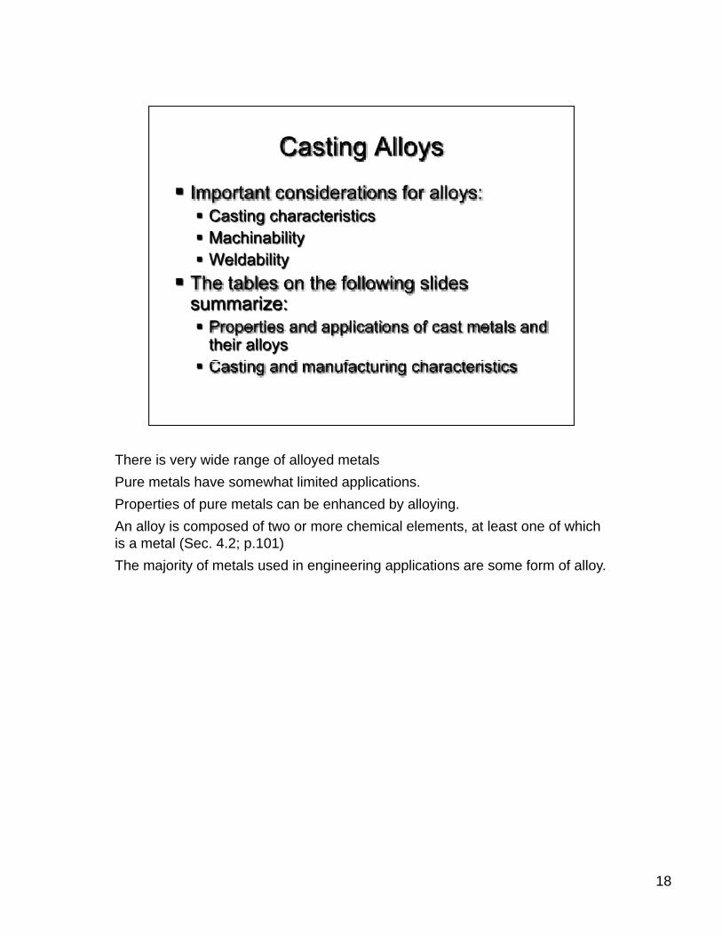
There is very wide range of alloyed metalsPure metals have somewhat limited applications.Properties of pure metals can be enhanced by alloying.An alloy is composed of two or more chemical elements, at least one of which is a metal (Sec. 4.2; p.101)The majority of metals used in engineering applications are some form of alloy.
18

19

20
21

22
23

24

25

26

27

Mo MolybdenumNb NiobiumW TungstenTa Tantalum
28
29

30

31

Machine tool base utilizes the high damping capacity of Gray C.I.
32

“Nodular” refers to the spheroid form of the graphite.This shape permits the material to be somewhat ductile and shock resistantThe shape of the graphite flakes is changed into nodules by small additions of Magnesium and/or Ceriium to molten metal prior to pouring. (Sec 4.6, p.111)
33

Hard & brittle because of presence of iron-carbide instead of graphiteObtained by either cooling gray iron rapidly or by adjusting the composition by keeping the carbon and silicon content lowCalled white iron because of the white crystalline appearance of the fracture (sec 4.6, p.111)
34

Malleable: “It can be hammered” (Latin)Obtained by annealing white C.I. in an atmosphere of Carbon Monoxide and Carbon Dioxide, at between 800oC and 900oC for up to several hours Graphite exists in clusters or rosettes
35

36

37
38

39

40

41

42