rolf · ksenthil kumar (audcoindia ltd) pursuant to license agreement. no enhet reproductions...
TRANSCRIPT
ROLFROLFENGG. SOLUTIONS INC.ENGG. SOLUTIONS INC.ROLFROLFENGG. SOLUTIONS INC.ENGG. SOLUTIONS INC.
Corp. Off. : C-16, Anand Bhuvan, 163/165, V. P. Road, Mumbai - 400 004. India. Tel. : +91 22 2389 4513 · Fax : +91 22 2389 4511Email : [email protected] · Website : www.rolfinc.com
Manufacturer & Exporters of High Tensile Carbon Steel, API 5L X52 to X70 PSL 1/2, LSAW, ERW & Seamless Pipes & Fittings,
Stainless Steel, Alloy Steel Pipes& Fittings, High Nickel Alloys, Monel, Inconel, Hastelloy, SMO254, Duplex, Super Duplex, Titanium-B2, B5 - Pipes & Fittings, Finned Tubes, Studded Pipes.

FOR INTERNAL REFERENCE ONLY
Designation: A 193/A 193M - 08
'uI TNTERRATI0NA1
Standard Specification for
Alloy-Steel and Stainless Steel Bolting Materials for High Temperature or High Pressure Service and Other Special Purpose Application 1
This stand:ird is issued uniJer the fixeiJ designation A 193/A l93M; the numbet immediately following the designation indicates the year of original adoption or, in the case of revision, the year of last revision. A number in parentheses indicates the year of last reapproval. A superscript epsilon (e) indicates an editorial change since the last revision or reapproval.
This standard hue heeii ‹ipyinve‹l for use by agencies oJ the Department of Defense.
1. Scope*
1.1 This specification' covers alloy and stainless steel bolt-
ing material for pressure vessels, valve.s, flanges, arid fittings
for high temperature or high pressure service, or other special
purpose applications. The term f›offing material in used in this
specification covers bars, bolts, screws, studs, stud bolts, and
wire. Bars and wire shall be hot-wrought. The material may be
further processed by centerless grinding or by cold drawing.
Austenitic stainless steel may be carbide solution treated or
carbide solution treated and strain-hardened. When strain
hardened austenitic steel is ordered, the purchaser should take
special care to ensure that Appendix X1 is thoroughly under-
stood.
1.2 Several grades are covered, including ferritic steels and
austenitic stainless steels designated BS, B8, and so forth.
Selection will depend upon design, service conditions, me-
chanical properties, and high temperature characteristics.
Now I—The committee formulating this specification has included fifteen steel types that have been rather extensively used for the present
1.5 This specification is expressed in both inch-pound units and in SI units. However, unless the order specifies the applicable 31 specification designation (SI units), the material shall be furnished to inch-pound units.
1.6 The values stated in either inch-pound units or SI units are to be regarded separately as standard. The values stated in each system are not exact equivalents; therefore, each system must be used independently of the other. Combining values from the two systems may result in nonconformance with the specification. Within the text, the SI units are shown in brackets.
2. Referenced Documents
2. 1 ASTM StanJards 3
A 153/A l53M Specification for Zinc Coating (Hot-Dip) on Iron and Steel Hardware
A 194/A 194M Specification for Carbon and Alloy Steel
Nuts for Bolts for High Pressure or High Temperature Service, or Both 320/A 320M Specification for Alloy-Steel and Stainless
purpose. Other compositions will be considered for i committee from time to time as the need becomes apparent.
the Steel Bolting Materials for Low-Temperature Service
Now 2—For grades of alloy-steel bolting material suitable for use at the lciwer range of high temperature applications, reference should be made to Specification A 354.
Nets 3—For grades of alloy-steel bolting material suitable for use in low tcmperaturc applications, i‘eference should bc made to Specification A 320/A 320M.
1.3 Nuts for use with this bolting material are covered In
Section 14.
1.4 Supplementary Requirements S1 through 510 are pro-
vided for use when additional tests or inspection are desired.
These shall apply only when specified in the purchase order.
This specification is under the jurisdiction of ASTM Committee A0l on Steel, -Stainless Steel arid Related Alloys and is the direct responsibility of Subcommittee
A01.22 on Steel Forgings and Wrought Fittings for Piping Applications and Bolting
Matei‘ials for Piping and Special Purpose Applications.
Current edition approved April I, 2008. Published May 2008. Originally approved in 1935. Last pfex'ious edition approved in 2007 as A I 93/A l93M-07.
'For ASME Boiler and Pressure Vessel Code applications, .sce relatetl Specifi- cation SA- 193 in Section II of that Code.
A 354 Specification for Quenched and Tempered Alloy Steel Bolts, Studs, and Other Externally Threaded Fasten- ers
A 788/A 788M Specification for Steel Forgings, General Requirements
A 962/A 962M Specification for Common Requirements for Steel Fasteners or Fastener Materials, or Both, Intended for Use at Any Temperature from Cryogenic to the Creep Range B 695 Specification for Coatings of Zinc Mechanically
Deposited on Iron and Steel B 696 Specification for Coatings of Cadmium Mechanically
Deposited
B 76G Specification for Electrodeposited Coatings of Cad-
'Por referenced ASTM standards, visit the ASJ'M website, www.astrn.org, or contact ASTM Customer Service at serviceiiI'astm.otg. Fot Annual Beak of ASTM Standards volume information, refer to the standard’s Document Summary page on the ASTM website.
*A Summary of Changes section appears at the end of thls standard.
Copyright ‹D ASTu International, 1oo Barr Harbor Drive, Po Box C700, west Consnohocken, PA 19428-2959, United States.
Copyright by ASTM Int'l (all rights reserved); Thu May 29 23:40:00 EDT 2008 Downloaded/printed by K Senthil Kumar (Audco India Ltd) pursuant to License Agreement. No Enhet reproductions authorized.
FOR INTERNAL REFERENCE ONLY
A 193/A 193M - 08
E lS Test Methods for Rockwell Hardness of Metallic 3.1.3 Nuts, if required by purchaser, in acco ance Materials 14. 1, 21 Test Methods for Elevated Temperature Tension Tests 3.1.4 Supplementary i’equirements, if any, and of Metallic Materials 3. 1.5 Special requirements, in accordance with 7.3, 7.5.1,
E 112 Test Methods for Determining Average Grain Size 11.2, 15. 1, and 16. 1. E 139 Test Methods for Conducting Creep, Creep-Rupture, 3.2 Coatings-----Coatings are prohibited unless specified by
and Stress-Rupture Tests of Metallic Materials the purchaser (See Supplementary Requirements 513 and 514). 150 Recommended Practice for Conducting Creep and When coated fasteners are ordered the purchaser should take Creep-Rupture Tension Tests of Metallic Materials Under special care to ensure that Appendix X2 is thoroughly under- Conditions of Rapid Heating and Short Time 4 stood. E 151 Recommended Practice for Tension Tests of Metallic
Materials at Elevated Temperatures With Rapid Heating
and Conventional or Rapid Strain Rates4
292 Te.st Methods for Conducting Time-for-Rupture
Notch Tension Tests of Materials
E .32b Test Methods for Stress Relaxation for Materials and
Structures
E 566 Practice for Electromagnetic (Eddy-Current) Sorting of Ferrous Metals
709 Guide for Magnetic Particle Testing
605 Pi’actice for Strain-Controlled Fatigue Testing
1940 Test Method for Process Control Verification to
Prevent Hydrogen Einbriulement in Plated or Coated Fasteners 1941 Specification for Electrodeposited Coatings on
Threaded Fasteners (Unified Inch Screw Threads (UN/ UNR))
2.2 ANSI Standards:-’ BI.1 Screw Threads B1II.2. 1 Square and Hex Bolts and Screws ii 18.2.3. IM Metric Hex Cap Screws BIS.3 Hexagon Socket and Spline Socket Screws B18.3. IM Mefi-ic Socket Head Cap Screws 2.3 AIAG Standard.
4. Common Requirements
4. 1 Material and fasteners supplied to this specification shall conform to the requirements of Specification A 962/A 962M. These requirements include test methods, finish, thread dimen- sions, marking, certification, optional supplementary require- ments, and others. Failure to comply with the requirements of Specification A 962/A 962M constitutes nonconformance with this specification. In case of conflict between this specification and Specification A 962/A 962M, this specification shall pre- vail.
5. Manufacture (Process)
5.1 The steel shall be produced by any of the following
processes: open-hearth, basic-oxygen, electric-furnace, or
vacuum-induction melting (VIM). The molten steel may be
vacuum-treated prior to or during pouring of the ingot or strand casting.
5.2 Quality----See Specification A 962/A 962M for require-
ments.
6. Discard
6.1 A sufficient discard shall be made to secure freedom from injurious piping and undue segregation.
AIAC› B-5. 02.00 Primary Metals Identification Tag Appli- cation Standard
3. General Requirements and Ordering Information
3.I The inquiry and orders shall include the following, as required, to describe the desired material adequately:
3.1.1 1 Heat-treated condition (that is, normalized and tem- pered, or quenched and tempered, for the fen4tic materials, and carbide solution treated (Class I ), carbide solution treated after finishing (Class IA), and carbide solution treated and strain- hardened (Classes 2, 2B and 2C), for the austenitic stainless steels; Classes IB and lC apply to the carbide solution-treated nitrogen-bearing stainless steels; Class lD applies to material carbide solution treated by cooling rapidly from the rolling temperature),
3.1.2 Description of items required (that is, bars, bolts, screws, or studs),
' Available from American National Stannards Institute (ANSI), 25 W. 43rd St., 4th Floor. New York, NY 10036, http:I/www.ansi.org.
" Available from Automotive Industry Action Group (AIAG), 26200 Lahser Rd.,
Suite 200, Southfield, MI 48033, http://www.aiag.org.
Copyright by ASTM Int'l (all rights reserved); Thu May 29 23:40:00 EDT 2008 Downloaded/printed by
7. Heat Treatment
7.1 Ferritic steels shall be properly heat treated as best suits the high temperature characteristics of each grade. Immedi- ately after rolling or forging, the bolting material shall be allowed to cool to a temperature below the cooling transfor- mation range. The materials which are to be furnished in the liquid-quenched condition shall then be uniformly reheated to the proper temperature to refine the grain (a group thus reheated being known as a quenching charge) and quenched in a liquid medium under substantially uniform conditions for each quenching charge. Use of water quenching is prohibited for any ferritic grade when heat treatment is part of the fastener manufacturing process. This prohibition does not apply to heat treated bar or to fasteners machined therefrom. The materials that are to be furnished in the normalized or air-quenched condition shall be reheated to the proper temperature to refine the grain and cooled uniformly in air to a temperature below the transformation temperature range. The material, whether liquid-quenched or normalized, shall then be uniformly re- heated for tempering. The minimum tempering temperature shall be as specified in Table 2 and Table 3.
2
K Senthil Kumar (Audco India Ltd) pursuant to License Agreement. No further reproductions authorized.
FOR INTERNAL REFERENCE ONLY
A 193/A 193M - 08
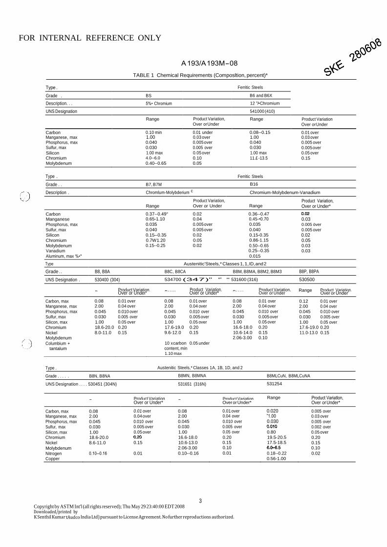
TABLE 1 Chemical Requirements (Composltion, percent)*
Type . Ferritic Steels Grade . BS B6 and B6X
Description. . . 5%• Chromium 12 °/• Chromium
UNS Designation 541000 (410)
Range Product Variation, Over or Under
Range Product Variation Over or Under
Carbon 0.10 min 0.01 under 0.08--0.15 0.01 over Manganese, max 1.00 0.03 over 1.00 0.03 over Phosphorus, max 0.040 0.005 over 0.040 0.005 over Sulfur, max 0.030 0.005 over 0.030 0.005 over
Silicon 1.00 max 0.05 over 1.00 max 0.05 over Chromium 4.0--6.0 0.10 11.£ -13.5 0.15 Molybdenum 0.40--0.65 0.05
Type .
Grade . .
Description .
B7, B7M
Chromlum-Molybderium c
Ferritic Steels
B16
Chromium-Molybdenum-Vanadium
Range
Type .
Grade . . . . . B8N, B8NA
UNS Designation . . . . 530451 (304N)
Austenitic Steels,* Classes 1A, 1B, 1D, and 2
B8MN, B8MNA
531651 (316N)
B8MLCuN, B8MLCuNA
531254
Range Product Variation,
Range Product Variation, Range Product Variatlon,
Over or Under* Over or Under* Over or Under*
Carbon, max 0.08 0.01 over 0.08 0.01 over 0.020 0.005 over Manganese, max 2.00 0.04 over 2.00 0.04 over ”1.00 0.03 over
Phosphorus, max 0.045 0.010 over 0.045 0.010 over 0.030 0.005 over Sulfur, max 0.030 0.005 over 0.030 0.005 over
0.002 over
Silicon, max 1.00 0.05 over 1.00 0.05 over 0.80 0.05 over Chromium 18.6-20.0
16.6-18.0 0.20 19.5-20.5 0.20 Nickel 8.6-11.0 0.15 10.6-13.0 0.15 17.5-18.5 0.15
Molybdenum 2.06-3.00 0.10
0.10
Nitrogen 0.10--0.16 0.01 0.10--0.16 0.01 0.18--0.22 0.02
Copper 0.56-1.00
3
Copyright by ASTM Int'l (all rights reserved); Thu May 29 23:40:00 EDT 2008 Downloaded/printed by K Senthil Kumar tAudco India Ltd) pursuant to License Agreement. No further reproductions authorized.
Range
Product Variation, Over or Under
Range
Product Variation, Over or Under*
Carbon 0.37--0.49° 0.02 0.36--0.47 Manganese 0.65-1.10 0.04 0.45-•0.70 0.03 Phosphorus, max 0.035 0.005 over 0.035 0.005 över
Sulfur, max 0.040 0.005 over 0.040 0.005 over Silicon 0.15--0.35 0.02 0.15-0.35 0.02 Chromium 0.7W1.20 0.05 0.86-1.15 0.05 Molybdenum 0.15--0.25 0.02 0.50--0.65 0.03 Vanadium 0.25--0.35 0.03
Aluminum, max %•* 0.015 Type Austenitic'Steels,* Classes 1, 1, ID, and 2
Grade . . B8, B8A B8C, B8CA B8M, B8MA, B8M2, B8M3 B8P, B8PA
UNS Designation . 530400 (304) 534700 (347)” "” " 531600 (316) 530500
Range Product Variation, Range
Product Variation, Range
Product Variation, Product Variation,
Over or Under* Over or Under* Over or Under
Over or Under’
Carbon, max 0.08 0.01 over 0.08 0.01 over 0.08 0.01 over 0.12 0.01 over Manganese, max 2.00 0.04 over 2.00 0.04 over 2.00 0.04 over 2.00 0.04 over Phosphorus, max 0.045 0.010 over 0.045 0.010 over 0.045 0.010 over 0.045 0.010 over Sulfur, max 0.030 0.005 over 0.030 0.005 over 0.030 0.005 over 0.030 0.005 over Silicon, max 1.00 0.05 over 1.00 0.05 over 1.00 0.05 over 1.00 0.05 over Chromium 18.6-20.0 0.20 17.6-19.0 0.20 16.6-18.0 0.20 17.6-19.0 0.20
Nickel 8.0-11.0 0.15 9.6-12.0 0.15 10.6-14.0 0.15 11.0-13.0 0.15 Molybdenum 2.06-3.00 0.10 Columbium + 10 x carbon 0.05 under
tantalum content, min; 1.10 max
FOR INTERNAL REFERENCE ONLY
A 193/A 193M - 08
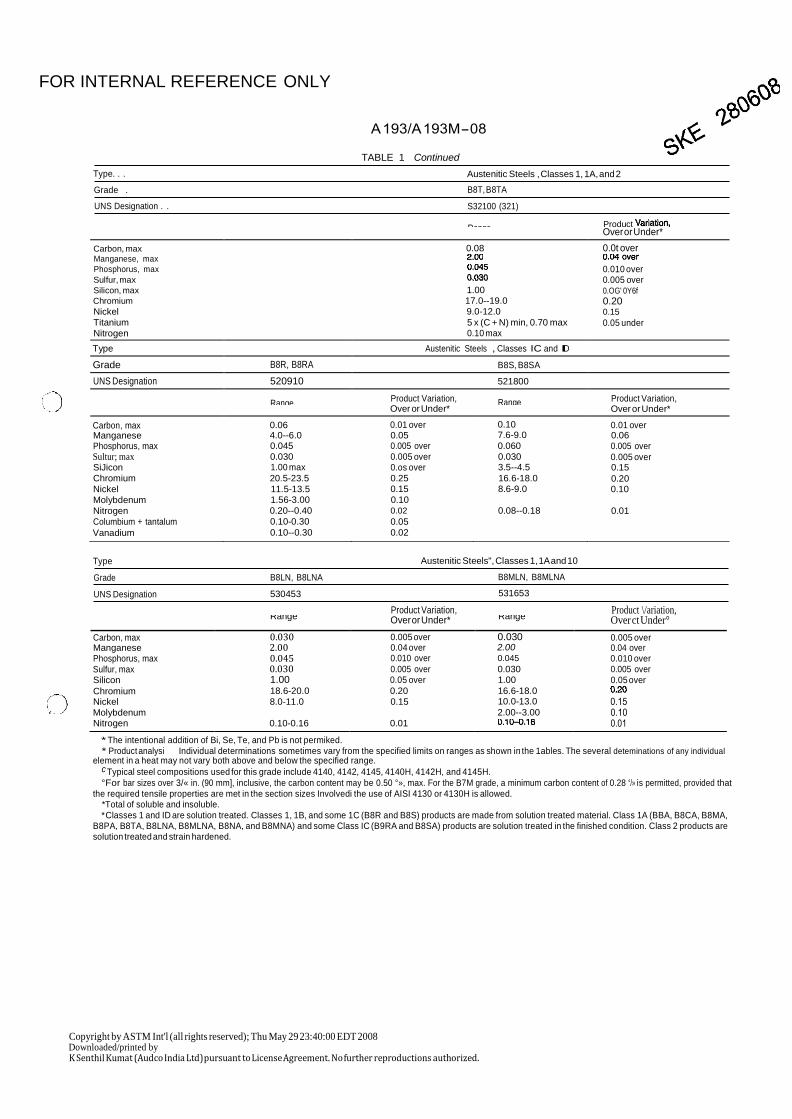
TABLE 1 Continued
Type. . .
Grade .
UNS Designation . .
Austenitic Steels , Classes 1, 1A, and 2
B8T, B8TA
S32100 (321)
Type
Grade
UNS Designation
B8LN, B8LNA
530453
Austenitic Steels", Classes 1, 1A and 10
B8MLN, B8MLNA
531653
Product Variation,
Product \/ariation,
* The intentional addition of Bi, Se, Te, and Pb is not permiked. * Product analysi Individual determinations sometimes vary from the specified limits on ranges as shown in the 1ables. The several deteminations of any individual
element in a heat may not vary both above and below the specified range. c Typical steel compositions used for this grade include 4140, 4142, 4145, 4140H, 4142H, and 4145H.
°For bar sizes over 3/« in. (90 mm], inclusive, the carbon content may be 0.50 °», max. For the B7M grade, a minimum carbon content of 0.28 °/» is permitted, provided that the required tensile properties are met in the section sizes Involvedi the use of AISI 4130 or 4130H is allowed.
*Total of soluble and insoluble. * Classes 1 and ID are solution treated. Classes 1, 1B, and some 1C (B8R and B8S) products are made from solution treated material. Class 1A (BBA, B8CA, B8MA,
B8PA, B8TA, B8LNA, B8MLNA, B8NA, and B8MNA) and some Class IC (B9RA and B8SA) products are solution treated in the finished condition. Class 2 products are solution treated and strain hardened.
Copyright by ASTM Int'l (all rights reserved); Thu May 29 23:40:00 EDT 2008 Downloaded/printed by K Senthil Kumat (Audco India Ltd) pursuant to License Agreement. No further reproductions authorized.
Range Over or Under* Range Over ct Under°
Carbon, max 0.030 0.005 over 0.030 0.005 over Manganese 2.00 0.04 over 2.00 0.04 over Phosphorus, max 0.045 0.010 over 0.045 0.010 over Sulfur, max 0.030 0.005 over 0.030 0.005 over Silicon 1.00 0.05 over 1.00 0.05 over
Chromium 18.6-20.0 0.20 16.6-18.0
Nickel 8.0-11.0 0.15 10.0-13.0 0.15 Molybdenum 2.00--3.00 0.10 Nitrogen 0.10-0.16 0.01 0.01
Range Product
Over or Under*
Carbon, max 0.08 0.0t over Manganese, max
Phosphorus, max 0.010 over
Sulfur, max 0.005 over
Silicon, max 1.00 0.OG' 0Y6f
Chromium 17.0--19.0 0.20 Nickel 9.0-12.0 0.15
Titanium 5 x (C + N) min, 0.70 max 0.05 under Nitrogen 0.10 max Type Austenitic Steels , Classes IC and ID Grade B8R, B8RA B8S, B8SA UNS Designation 520910 521800
Range Product Variation, Range Product Variation,
Over or Under*
Over or Under*
Carbon, max 0.06 0.01 over 0.10 0.01 over Manganese 4.0--6.0 0.05 7.6-9.0 0.06 Phosphorus, max 0.045 0.005 over 0.060 0.005 over Sultur; max 0.030 0.005 over 0.030 0.005 over SiJicon 1.00 max 0.os over 3.5--4.5 0.15 Chromium 20.5-23.5 0.25 16.6-18.0 0.20 Nickel 11.5-13.5 0.15 8.6-9.0 0.10 Molybdenum 1.56-3.00 0.10 Nitrogen 0.20--0.40 0.02 0.08--0.18 0.01
Columbium + tantalum 0.10-0.30 0.05 Vanadium 0.10--0.30 0.02
FOR INTERNAL REFERENCE ONLY
A 193/A 193M - 08
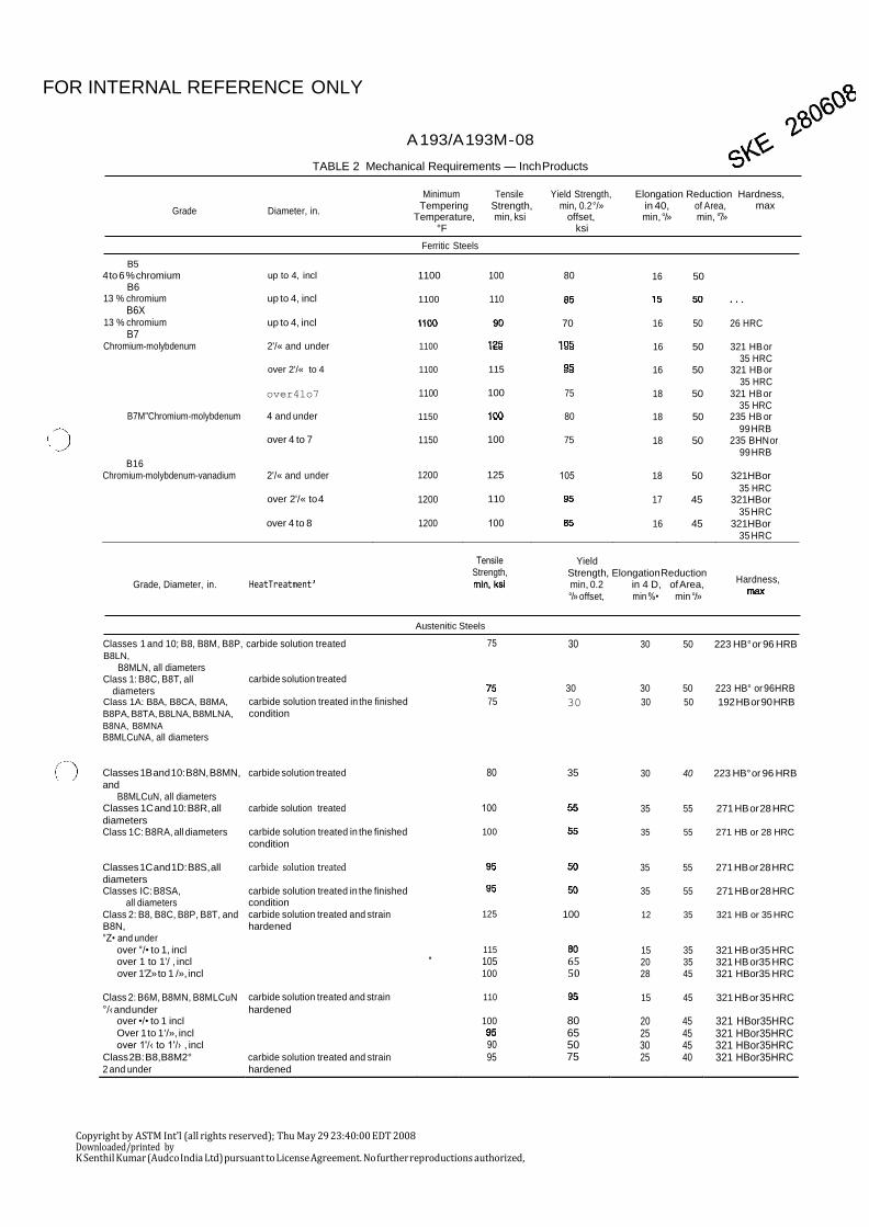
TABLE 2 Mechanical Requirements — Inch Products
Grade
Diameter, in.
Minimum Tensile Yield Strength, Elongation Reduction Hardness,
B5
4 to 6 % chromium B6
13 % chromium
B6X 13 % chromium
B7
B16
up to 4, incl
up to 4, incl
up to 4, incl
Ferritic Steels
1100
1100
100 80
110
70
16 50
16 50 26 HRC
Grade, Diameter, in.
HeatTreatment’
Tensile Strength,
Yield
Strength, Elongation Reduction min, 0.2 in 4 D, of Area, °/» offset, min %• min °/»
Hardness,
Classes 1 and 10; B8, B8M, B8P, carbide solution treated B8LN,
B8MLN, all diameters
Austenitic Steels
75
30 30 50 223 HB° or 96 HRB
Class 1: B8C, B8T, all diameters
carbide solution treated
30 30 50 223 HB° or 96HRB
Copyright by ASTM Int'l (all rights reserved); Thu May 29 23:40:00 EDT 2008 Downloaded/printed by K Senthil Kumar (Audco India Ltd) pursuant to License Agreement. No further reproductions authorized,
Class 1A: B8A, B8CA, B8MA,
B8PA, B8TA, B8LNA, B8MLNA,
carbide solution treated in the finished condition
75 30 30 50 192 HB or 90 HRB
B8NA, B8MNA B8MLCuNA, all diameters
Classes 1B and 10: B8N, B8MN,
carbide solution treated
80
35
30
40
223 HB° or 96 HRB and
B8MLCuN, all diameters Classes 1C and 10: B8R, all carbide solution treated 100
35 55 271 HB or 28 HRC diameters Class 1C: B8RA, all diameters carbide solution treated in the finished 100
35 55 271 HB or 28 HRC
condition Classes 1C and 1D: B8S, all carbide solution treated
35 55 271 HB or 28 HRC diameters Classes IC: B8SA, carbide solution treated in the finished
35 55 271 HB or 28 HRC all diameters condition
Class 2: B8, B8C, B8P, B8T, and carbide solution treated and strain 125 100 12 35 321 HB or 35 HRC
B8N, hardened °Z• and under
over °/• to 1, incl 115
15 35 321 HB or35 HRC over 1 to 1'/ , incl ’ 105 65 20 35 321 HB or35 HRC over 1'Z» to 1 /», incl 100 50 28 45 321 HBor35 HRC
Class 2: B6M, B8MN, B8MLCuN carbide solution treated and strain 110
15 45 321 HB or 35 HRC °/‹ and under hardened
over •/• to 1 incl 100 80 20 45 321 HBor35HRC Over 1 to 1 '/», incl
65 25 45 321 HBor35HRC over 1'/‹ to 1'/› , incl 90 50 30 45 321 HBor35HRC
Class 2B: B8, B8M2° carbide solution treated and strain 95 75 25 40 321 HBor35HRC 2 and under hardened
Chromium-molybdenum 2'/« and under 1100
16 50 321 HB or
35 HRC over 2'/« to 4 1100 115 16 50 321 HB or
35 HRC
over4lo7 1100 100 75 18 50 321 HB or
B7M"Chromium-molybdenum 4 and under
1150
80
18
50 35 HRC
235 HB or
over 4 to 7
1150
100
75
18
50 99 HRB
235 BHN or
99 HRB
Chromium-molybdenum-vanadium 2'/« and under 1200 125 105 18 50 321HBor
35 HRC over 2'/« to 4 1200 110 17 45 321HBor
35 HRC over 4 to 8 1200 100 16 45 321HBor
35 HRC
Tempering Temperature,
Strength, min, ksi
min, 0.2 °/» offset,
in 40, min, °/»
of Area, min, °7»
max
°F ksi
FOR INTERNAL REFERENCE ONLY
A 193/A 193M - 08
Grade, Diameter, in. Heat Treatments
Strength, min, ksi
Austenitic Steels
Strength, Elongation Reduction min, 0.2 in 4 D, of Area, °/• offset, min °/» min °/<
ksi
Hardness,
over 2 to 2'/a incl 90
30 40 321 HB or35 HRC over 2'/« to 3 incl 55 30 40 321 HB or35 HRC
Class 2C: B8M3“ carbide solution treated and strain 65 30 60 321 HBor35 HRC 2 and under hardened
over 2
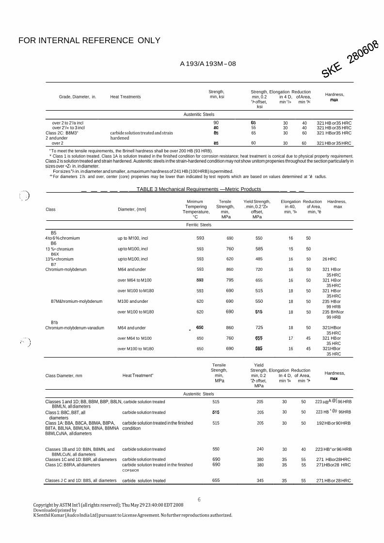
" To meet the tensile requirements, the Brinell hardness shall be over 200 HB (93 HRB).
60 30 60 321 HB or 35 HRC
* Class 1 is solution treated. Class 1A is solution treated in the finished condition for corrosion resistance; heat treatment is conical due to physical property requirement. Class 2 is solution treated and strain hardened. Austenitic steels in the strain-hardened condition may not show unitom propenies throughout the section particularly in sizes over •Z‹ in. in diameter.
For sizes "/‹ in. in diameter and smaller, a maximum hardness of 241 HB (100 HRB) is permitted. °For diameters 1'/s and over, center (core) propenies may be lower than indicated by test reports which are based on values determined at '/e radlus.
TABLE 3 Mechanical Requirements —Metric Products
Class
Diameter, (mm]
Minimum Tensile Yield Strength, Elongation Reduction Hardness,
B5 4 to 6 % chromium
B6
up to M100, incl
Ferritic Steels
593
690
550
16 50
B1b
Class Diameter, mm
Heat Treatment“
Tensile
Strength, min,
MPa
Austenitic Steels
Yield Strength, Elongation Reduction min, 0.2 In 4 D, of Area, °Z• offset, min °/« min °/•
MPa
Hardness,
Classes 1 and 1D; BB, BBM, B8P, B8LN, carbide solution treated B8MLN, all diameters
515 205 30 50 223 HBA @[ 96 HRB
Class 1: B8C, B8T, all diameters
Class 1A: B8A, B8CA, B8MA, B8PA, B8TA, B8LNA, B8MLNA, B8NA, B8MNA B8MLCuNA, all diameters
Classes 1B and 10: B8N, B8MN, and
B8MLCuN, all diameters
carbide solution treated
carbide solution treated in the finished condition
carbide solution treated
515
550
205
205
240
30 50 223 HB * @p 96HRB
30 50 192 HB or 90 HRB
30 40 223 HB° or 96 HRB
Classes 1C and 1D: B8R, all diameters carbide solution treated 690 380 35 55 271 HBor28HRC Class 1C: B8RA, all diameters carbide solution treated in the finished
COF§itlOfl
690 380 35 55 271HBor28 HRC
Classes J C and 1D: B8S, all diameters carbide solution treated 655 345 35 55 271 HB or 28 HRC
6 Copyright by ASTM Int'l (all rights reserved); Thu May 29 23:40:00 EDT 2008 Downloaded/printed by K Senthil Kumar (Audco India Ltd) pursuant to License Agreement. No further reproductions authorized.
13 %• chromium B6X
up to M100, incl 593 760 585 15 50
13 %• chromium up to M100, incl 593 620 485 16 50 26 HRC
B7 Chromium-molybdenum M64 and under 593 860 720 16 50 321 HB or
over M64 to M100
795
655
16
50
35 HRC 321 HB or
over M100 to M180
593
690
515
18
50
35 HRC 321 HB or
35 HRC B7M&hromium-molybdenum M100 and under 620 690 550 18 50 235 HB or
over M100 to M180
620
690 18
50
99 HRB 235 BHN or
99 HRB
Chromium-molybdenum-vanadium M64 and under 860 725 18 50 321HBor
over M64 to M100
650
760
17
45 35 HRC
321 HB or
over M100 to M180
650
690
16
45 35 HRC
321HBor
35 HRC
Tempering Temperature,
Strength, min,
. min, 0.2 °Z» offset,
in 40, min, °/»
of Area, min, °é
max
°C MPa MPa
FOR INTERNAL REFERENCE ONLY
A 193/A 193M - 08
Class Diameter, mm l9eatTreatment’
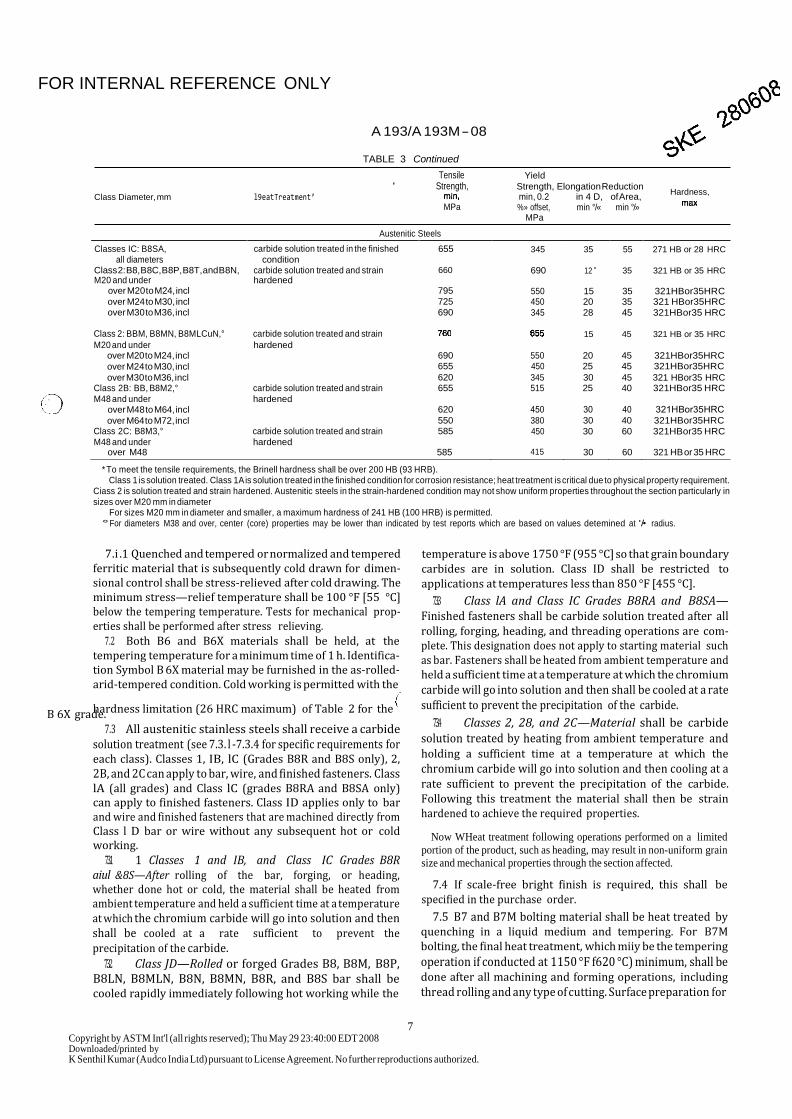
TABLE 3 Continued
Tensile ' Strength,
MPa
Austenitic Steels
Yield
Strength, Elongation Reduction min, 0.2 in 4 D, of Area, %» offset, min °/« min °/»
MPa
Hardness,
* To meet the tensile requirements, the Brinell hardness shall be over 200 HB (93 HRB). Class 1 is solution treated. Class 1A is solution treated in the finished condition for corrosion resistance; heat treatment is critical due to physical property requirement.
Ciass 2 is solution treated and strain hardened. Austenitic steels in the strain-hardened condition may not show uniform properties throughout the section particularly in sizes over M20 mm in diameter
For sizes M20 mm in diameter and smaller, a maximum hardness of 241 HB (100 HRB) is permitted.
°For diameters M38 and over, center (core) properties may be lower than indicated by test reports which are based on values detemined at '/• radius.
7.i .1 Quenched and tempered or normalized and tempered ferritic material that is subsequently cold drawn for dimen- sional control shall be stress-relieved after cold drawing. The minimum stress—relief temperature shall be 100 °F [55 °C] below the tempering temperature. Tests for mechanical prop- erties shall be performed after stress relieving.
7.2 Both B6 and B6X materials shall be held, at the tempering temperature for a minimum time of 1 h. Identifica- tion Symbol B 6X material may be furnished in the as-rolled- arid-tempered condition. Cold working is permitted with the
hardness limitation (26 HRC maximum) of Table 2 for the B 6X grade.
7.3 All austenitic stainless steels shall receive a carbide solution treatment (see 7.3. l -7.3.4 for specific requirements for each class). Classes 1, IB, lC (Grades B8R and B8S only), 2, 2B, and 2C can apply to bar, wire, and finished fasteners. Class lA (all grades) and Class lC (grades B8RA and B8SA only) can apply to finished fasteners. Class ID applies only to bar and wire and finished fasteners that are machined directly from Class l D bar or wire without any subsequent hot or cold working.
7.3.1 1 Classes 1 and IB, and Class IC Grades B8R aiul &8S—After rolling of the bar, forging, or heading, whether done hot or cold, the material shall be heated from ambient temperature and held a sufficient time at a temperature at which the chromium carbide will go into solution and then shall be cooled at a rate sufficient to prevent the
precipitation of the carbide. 7.3.2 Class JD—Rolled or forged Grades B8, B8M, B8P,
B8LN, B8MLN, B8N, B8MN, B8R, and B8S bar shall be cooled rapidly immediately following hot working while the
temperature is above 1750 °F (955 °C] so that grain boundary carbides are in solution. Class ID shall be restricted to applications at temperatures less than 850 °F [455 °C].
7.3.3 Class lA and Class IC Grades B8RA and B8SA— Finished fasteners shall be carbide solution treated after all rolling, forging, heading, and threading operations are com- plete. This designation does not apply to starting material such as bar. Fasteners shall be heated from ambient temperature and held a sufficient time at a temperature at which the chromium
carbide will go into solution and then shall be cooled at a rate sufficient to prevent the precipitation of the carbide.
7.3.4 Classes 2, 28, and 2C—Material shall be carbide solution treated by heating from ambient temperature and holding a sufficient time at a temperature at which the
chromium carbide will go into solution and then cooling at a rate sufficient to prevent the precipitation of the carbide. Following this treatment the material shall then be strain hardened to achieve the required properties.
Now WHeat treatment following operations performed on a limited
portion of the product, such as heading, may result in non-uniform grain
size and mechanical properties through the section affected.
7.4 If scale-free bright finish is required, this shall be specified in the purchase order.
7.5 B7 and B7M bolting material shall be heat treated by quenching in a liquid medium and tempering. For B7M bolting, the final heat treatment, which miiy be the tempering
operation if conducted at 1150 °F f620 °C) minimum, shall be done after all machining and forming operations, including
thread rolling and any type of cutting. Surface preparation for
7 Copyright by ASTM Int'l (all rights reserved); Thu May 29 23:40:00 EDT 2008 Downloaded/printed by K Senthil Kumar (Audco India Ltd) pursuant to License Agreement. No further reproductions authorized.
Classes IC: B8SA, all diameters
Class 2: B8, B8C, B8P, B8T, and B8N,
carbide solution treated in the finished condition
carbide solution treated and strain
655
660
345
690
35
12 ”
55
35
271 HB or 28 HRC
321 HB or 35 HRC
M20 and under hardened over M20 to M24, incl 795 550 15 35 321HBor35HRC over M24 to M30, incl 725 450 20 35 321 HBor35HRC over M30 to M36, incl 690 345 28 45 321HBor35 HRC
Class 2: BBM, B8MN, B8MLCuN,° carbide solution treated and strain
15 45 321 HB or 35 HRC
M20 and under hardened over M20 to M24, incl 690 550 20 45 321HBor35HRC
over M24 to M30, incl 655 450 25 45 321HBor35HRC
over M30 to M36, incl 620 345 30 45 321 HBor35 HRC Class 2B: BB, B8M2,° carbide solution treated and strain 655 515 25 40 321HBor35 HRC M48 and under hardened
over M48 to M64, incl 620 450 30 40 321HBor35HRC
over M64 to M72, incl 550 380 30 40 321HBor35HRC Class 2C: B8M3,° carbide solution treated and strain 585 450 30 60 321HBor35 HRC M48 and under hardened
over M48 585 415 30 60 321 HB or 35 HRC

FOR INTERNAL REFERENCE ONLY
A 193/A 193M - 08
hardness testing, nondestructive evaluation, or ultrasonic bolt
tensioning is permitted. 7.5.1 Unless otherwise specified, material for Grade B7 may
where:
As —- 0.785 (D -(0.974/II))' (2)
be heat treated by the Furnace, the Induction or the Electrical
Resistance method.
Note 5—It should be taken into consideration that stress-relaxation properties may vary from heat lot to heat lot or these properties may vary from one heat treating method to another. The purchaser may specify Supplementary Requirement 58, if stress-rel:ixation testing is desired.
7.6 Material Grade B16 shall be heated to a temperature
range from 1700 to 1750 °F [925 to 955 °C] and oil quenched. The minimum tempering temperature shall be as specified in
Table 2.
D -- nominal thread size, and n -- the number of threads pei inch.
10.2 Hardness Requirements: 10.2.1 1 The hardness shall conform to the
requirements prescribed in Table 2. Hardness testing shall be performed in accordance with either Specification A 962/A 962M or with Test Methods F 606.
10.2.2 Grade BZ4f—The maximum hardness of the grade shall be 235 HB or 99 HRB. The minimum hardness shall not be less than 200 HB or 93 HRB. Conformance to this hardness shall be ensured by testing the hardness of each stud or bolt by Brinell or Rockwell B methods in accordance with 10.2. 1. The
8. Chemical Composition use of 100 9o’ electromagnetic testing for hardness as an 5.1 Each alloy sl1al1 GORfOITf1 to th€: C•hemica1 composition
iequirements prescribed in Table 1.
8.2 The steel shall not contain an unspecified element for
the ordered grade to the extent that the steel conforms to the
requirements of another grade for which that element is a
specified element. Furthermore, elements present in concentra-
tions greater than 0.75 weight/7o shall be reported.
9. Heat Analysis
9.1 An analysis of each heat of steel shall be made by the
manufacturer to determine the percentages of the elements
specified in Section 8. The chemical composition thus deter-
mined shall be reported to the purchaser or the purchaser’s
repiesentative, and shall conform to the requirements specified
in Section S. Should the purchaser’ deem it necessary to have
the transition zone of two heats sequentially cast discarded, the
purchaser shall invoke Supplementary Requirement 53 of
Specification A 788.
10. Mechanical Properties
10.1 Tensile Properties. 10.1.1 Requirements—The material as represented by the
tension specimens shall conform to the requiiements pre-
scribed in Table 2 at room temperature after heat treatment. Alternatively, stainJess strain hardened headed fasteners (Class
2, 2B, and 2C) shall be tested full size after strain hardening to
deteimine tensile strength and yield strength and shall conform
to the requiiements piescribed in Table 2. Should the results of
full size tests conflict with results of tension specimen tests,
full size test results shall prevail.
10.1.2 Full Site .Fasteners, hedge Tensile Testing—When
applicable, see 13.1.3, headed fasteners shall be wedge tested
full size and shall conform to the tensile strength shown in
Table 2. The minimum full size breaking strength (lbf) for
individual sizes shall be as follows:
(1)
wheie: Ts -- wedge tensile strength, UTS —- tensile strength speci5ed in "fable 2, and As -- stress area, square inches, as shown in ANSI BI .1 or
calculated as follows:
Copyright by ASTM Int'l (all rights reserved); Thu May 29 23:40:00 EDT 2008 Downloade‹f'printed by
alternative to 100 9n' indentation hardness testing is permissible when qualified by sampling using indentation hardness testing. Each lot tested foi hardness electromagnetically shall be 100 9o' examined in accordance with Practice E 5ti6. Following elec- tromagnetic testing for hardness a random sample of a mini- mum of 100 pieces of each heat of steel in each lot (as defined in 13. 1.1) shall be tested by indentation hardness methods. All samples must meet hardness requirements to permit acceptance of the lot. If any one sample is outside of the specified maximum or minimum hardness, the lot shall be rejected and either reprocessed and iesampled or tested 100 9o' by indenta- tion hardness methods. Product that has been 100 '7o tested and found acceptable shall have a line under the grade symbol.
10.2.2. 1 Surface preparation for indentation hardness test- ing shall be in accordance with Test Methods E 18. Hardness tests shall be performed on the end of the bolt or stud. When this is impractical, the hardness test shall be performed elsewhere.
11. Workmanship, Finish, and Appearance
11.1 Bolts, screws, studs, and stud bolts shall be pointed and shall have a workmanlike finish. Points shall be flat and chamfered or rotinded at option of the manufacturer. Length of point on studs and stud bolts shall be not less than one nor more than two complete threads as measured from the extreme end parallel to the axis. Length of studs and stud bolts shall be measured from first thread to first thread.
11.2 Bolt heads shall be in accordance with the dimensions of ANSI B15.2. 1 or ANSI B1S.2.3. lM. Unless otherwise specified in the purchase order, the Heavy Hex Screws Series should be used, except the maximum body diameter and radius of fillet may be the same as for the Heavy Hex Bolt Series. The body diameter and head fillet radius for sizes of Heavy Hex Cap Screws and Bolts that are not shown in their respective tables in ANSI B18.2. I or ANSI B18.2.3. lM may be that shown in the corresponding Hex Cap Screw and Bolt Tables respectively. Socket head fasteners shall be in accordance with ANSI B18.3 or ANSI B18.3. lM.
12. Retests
12. I If the results of the mechanical tests of any test lot do not conform to the requirements specified, the manufacturer may retreat such lot not more than twice, in which case two
8
K Senthil Kumar (Audco India Ltd) pursuant to License Agreement. No further reproductions authorized.

FOR INTERNAL REFERENCE ONLY
A 193/A t93M - 08
additional tension tests shall be made from such lot, all of 16. Certification
which shall conform to the requirements speCifiéd. 16.1 The producer of the raw material or finished fasteners
shall furnish a certification to the purchaser or his representa- 13. Test Specimens
13. 1 Number of Tests—Not heat-treated bars, one tension test shall be made for each diameter of each heat represented in each tempering charge. When heat treated without interruption in continuous furnaces, the material in a lot shall be the same heat, same prior condition, same size, and subjected to the same heat treatment. Not fewer than two tension tests are required for each lot containing 20 000 lb [9000 kg] or less. Every additional 10 000 lb [4500 kg) or fraction thereof requires one additional test.
13. 1. 1 For studs, bolts, screws, and so forth, one tension test shall be made for each diameter of each heat involved in the Jot. Each lot shall consist of the following:
tive showing the results of the chemical analysis, macroetch examination (Carbon and Alloy Steels Only), and mechanical tests, and state the method of heat treatment employed.
16.2 Certification shall also include at least the following: 16.2. I A statement that the material or the fasteners, or both,
were manufactured, sampled, tested, and inspected in accor- dance with the specification and any supplementary require- ments or other requirements designated in the purchase order or contract and was found to meet those requirements.
16.2.2 The specification number, year date, and identifica- tioi symbol.
17. Product Marking 17.1 The marking symbol and manufacturer’s identification
Diameter, in. [mmJ 1'/e [30] and under
Over 1°Z‹ [42] to 2'Z« [64], incl
Over 2'/s [64]
Lot Size • 1500 lb [780 kgJ or fraction thereof 4500 lb [2000 kgJ or fraction thereof 60o0 lb [2700 kg] or fraction thereof 100 pieces or fraction thereof
symbol shall be applied to one end of studs °/« in. [10 mm] in diameter and larger and to the heads of bolts '/4 in. [6 mm] in diameter and larger. (If the available area is inadequate, the marking symbol may be placed on one end with the manufac-
13.1.2 Tension tests are not required to be made on bolts, screws, studs, or stud bolts that are fabricated from heat-treated bars furnished in accordance with the requirements of this specification and tested in accordance with 13.1, provided they are not given a subsequent heat treatment.
13.1.3 Full Size Specimens, Headed Fasteners—headed fasteners 1'/z in. in body diameter and smaller, with body length three times the diameter or longer, and that are produced by upsetting or forging (hot or cold) shall be subjected to full size testing in accordance with 10.1.2. This testing shall be in addition to tensile testing as specified in 10. 1.1. The lot size shall be as shown in 13.1. 1. Failure shall occur in the body or threaded section with no failure, or indications of failure, such as cracks, at the junction of the head and shank.
14. Nuts
14.1 Bolts, studs, and stud bolts shall be furnished with nuts, when specified in the purchase order. Nuts shall conform
to Specification A 194/A 194M.
15. Rejection and Rehearing
15.1 1 Unless otherwise specified in the basis of purchase, any rejection based on product analysis shall be reported to the manufacturer within 30 days front the receipt of samples by the purchaser.
15.2 Material that shows defects subsequent to its accep- tance at the place of manufacture shall be rejected, and the manufacturer shall be notified.
15.3 Product Are/ysis—Samples that represent rejected ma-
turer’s identification symbol placed on the other end.) The marking symbol shall be as shown in Table 4 and Table S. Grade B7M, which has been 100 9o' evaluated in conformance with the specification, shall have a line under the marking symbol to distinguish it from B7M produced to previous specification revisions not requiring 100 9o' hardness testing.
17.2 For bolting materials, including threaded bars, fur- nished bundled and tagged or boxed, the tags and boxes shall carry the marking symbol for the material identification and the manufacturer’s identification symbol or name.
17.3 For purposes of product marking, the manufacturer is considered the organization that certifies the fastener was manufactured, sampled, tested, and inspected in accordance with the specification and the results have been determined to meet the requirements of this specification.
17.4 Bar Coding—In addition to the requirements in 17.1, I 7.2, and 17.3, bar coding is acceptable as a supplementary identification method. Bar coding should be consistent with AIAG Standard B-5 02.00. If used on small items, the bar code may be applied to the box or a substantially applied tag.
18. Keywords
I 8.1 hardness; heat treatment
TABLE 4 Marking of Ferritic Steels
t3rade 'landing Symbol
B5 B5
B6 B6
B6X B6X
B7 B7
B7M* B7M BOM
terial shall be preset-red for two weeks from the date of the test report. In the case of dissatisfaction with the results of the test, the manufacturer may make claim for a rehearing within that time.
B16 B16 +
Supplement S12
° For explanations, see 10.2.2 and 17.1.
B16 B16R
Copyright by ASTM Int'l (all rights reserved); Thu May 29 23:40:00 EDT 2008 Dovm1oaded/allotted by K Senthil Kumat (Audco India Ltd) pursuant to License Agreement. No further reproductions authorized.

FOR INTERNAL REFERENCE ONLY
A 193/A 193M - 08
TABLE 5 Marking of Austenitic Steels
Grade Marking Symbol
Class 1 B8 B8
B8C BBM
B8C BBM
.B8P B8P
B8T B8T
B8LN B8F or B8LN
B8MLN B8G or B8MLN
Class 1A B8A B8A
B8CA B8B or B8CA
B8MA B8PA
B8D or B8MA B8H or B8PA
B8TA B8J or B8TA
B8LNA B8L or B8LNA
B8MLNA B8K or B8MLNA
B8NA B8V or B8MA
B8MNA B8W or B8MNA
B8MLCuNA B9K or B8MLCuNA
Class 1B B8N B8N
B8MN B8Y or B8MN
B8MLCuN B9J or B8MLCuN
Class 1C B8R B9A or B8R
B8RA B9B or B8RA
B8S B9D or B8S
B8SA B9F or B8SA
Class 10 B8 B94
B8kl B95
B8P B96
B8LN B97
B8MLN B98
B8N B99
B8MN B8R
B100
B101
B8S B102
B8
B8SH
B8C B8CSH
B8P B8PSH
B8T B8TSH
B8N B8NSH
B8M B8MSH
B8kJN B8YSH
B8MLCuN BOJSH
Class 2B B8M2 B9G or B8M2
BB {}
Class 2C B8M3 B9H or B8M3
SUPPLEMENTARYREQUIREMENTS
These requirements shall not apply unless specified in the order and in the Ordering Information,
in which event the specified tests shall be made before shipment of the product.
51. High Temperature Tests as agreed between the manufacturer and the purchaser. When
51.1 Tests to determine high temperature properties shall be testing temperatures are as low as those specified in Specifi-
made in accoi’dance with Test Methods E 2J , E 139, and E 292, Catiofl A 320/A 320M, bolting should be ordered to that speci-
and Practices E 1.50 and E 15I . fixation in preference to this specification.
52. Charpy Impact Tests
52.1 Charpy impact tests based on the requirements of Specification A 320/A 320M, Sections 6 and 7, shall be made
10 Copyright by ASTM Int'l (all rights reserved); Thu May 29 23:40:00 EDT 2008 Downloaded/printed by K Senthil Kumar (Audco India Ltd) pursuant to License Agreement. No further reproductions authorized.
FOR INTERNAL REFERENCE ONLY
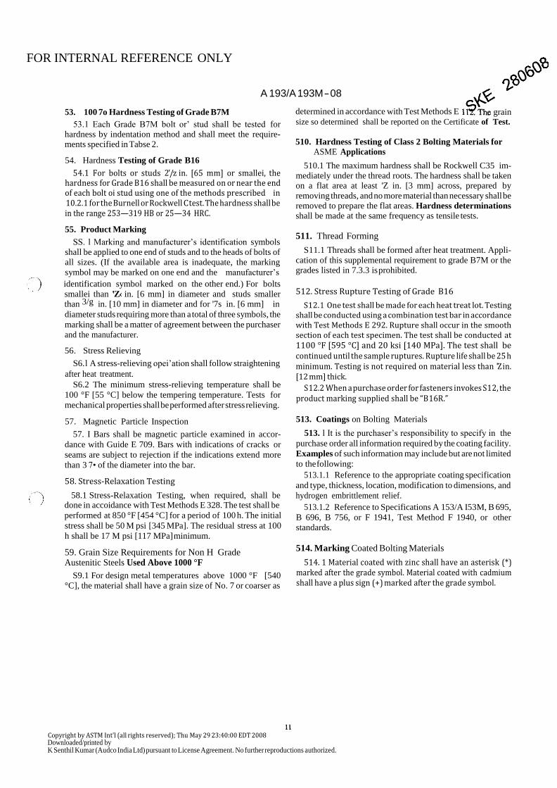
53. 100 7o Hardness Testing of Grade B7M
A 193/A 193M - 08
determined in accordance with Test Methods E
grain
53.1 Each Grade B7M bolt or’ stud shall be tested for hardness by indentation method and shall meet the require- ments specified in Tabse 2.
54. Hardness Testing of Grade B16
54.1 For bolts or studs 2'/z in. [65 mm] or smallei, the hardness for Grade B16 shall be measured on or near the end of each bolt oi stud using one of the methods prescribed in 10.2. 1 for the Burnell or Rockwell C test. The hardness shall be in the range 253—319 HB or 25—34 HRC.
55. Product Marking
SS. l Marking and manufacturer’s identification symbols
shall be applied to one end of studs and to the heads of bolts of
all sizes. (If the available area is inadequate, the marking
symbol may be marked on one end and the manufacturer’s
identification symbol marked on the other end.) For bolts
smallei than 'Z‹ in. [6 mm] in diameter and studs smaller than 3/g in. [10 mm] in diameter and for '7s in. [6 mm] in
diameter studs requiring more than a total of three symbols, the
marking shall be a matter of agreement between the purchaser
and the manufacturer.
56. Stress Relieving
S6. l A stress-relieving opei’ation shall follow straightening
after heat treatment.
S6.2 The minimum stress-relieving temperature shall be
100 °F [55 °C] below the tempering temperature. Tests for
mechanical properties shall be performed after stress relieving.
57. Magnetic Particle Inspection
57. I Bars shall be magnetic particle examined in accor-
dance with Guide E 709. Bars with indications of cracks or
seams are subject to rejection if the indications extend more
than 3 7• of the diameter into the bar.
58. Stress-Relaxation Testing
58.1 Stress-Relaxation Testing, when required, shall be done in accoidance with Test Methods E 328. The test shall be
performed at 850 °F [454 °C] for a period of 100 h. The initial
stress shall be 50 M psi [345 MPa]. The residual stress at 100
h shall be 17 M psi [117 MPa] minimum.
59. Grain Size Requirements for Non H Grade Austenitic Steels Used Above 1000 °F
S9.1 For design metal temperatures above 1000 °F [540
°C], the material shall have a grain size of No. 7 or coarser as
size so determined shall be reported on the Certificate of Test.
510. Hardness Testing of Class 2 Bolting Materials for ASME Applications
510.1 The maximum hardness shall be Rockwell C35 im- mediately under the thread roots. The hardness shall be taken on a flat area at least 'Z in. [3 mm] across, prepared by
removing threads, and no more material than necessary shall be removed to prepare the flat areas. Hardness determinations
shall be made at the same frequency as tensile tests.
511. Thread Forming
S11.1 Threads shall be formed after heat treatment. Appli-
cation of this supplemental requirement to grade B7M or the grades listed in 7.3.3 is prohibited.
512. Stress Rupture Testing of Grade B16
S12. 1 One test shall be made for each heat treat lot. Testing shall be conducted using a combination test bar in accordance with Test Methods E 292. Rupture shall occur in the smooth section of each test specimen. The test shall be conducted at 1100 °F [595 °C] and 20 ksi [140 MPa]. The test shall be continued until the sample ruptures. Rupture life shall be 25 h minimum. Testing is not required on material less than 'Z in. [12 mm] thick.
S 12.2 When a purchase order for fasteners invokes S12, the product marking supplied shall be “B 16R.”
513. Coatings on Bolting Materials
513. l It is the purchaser’s responsibility to specify in the
purchase order all information required by the coating facility.
Examples of such information may include but are not limited
to the following:
513.1.1 Reference to the appropriate coating specification
and type, thickness, location, modification to dimensions, and
hydrogen embrittlement relief.
513.1.2 Reference to Specifications A 153/A I53M, B 695,
B 696, B 756, or F 1941, Test Method F 1940, or other
standards.
514. Marking Coated Bolting Materials
514. 1 Material coated with zinc shall have an asterisk (*) marked after the grade symbol. Material coated with cadmium shall have a plus sign (+) marked after the grade symbol.
Copyright by ASTM Int'l (all rights reserved); Thu May 29 23:40:00 EDT 2008 Downloaded/printed by K Senthil Kumar (Audco India Ltd) pursuant to License Agreement. No further reproductions authorized.
FOR INTERNAL REFERENCE ONLY
A 193/A 193M - 08
APPENDIXES
(Nonmandatory Information)
XLfTRAINHARDENINC 0FAUSTENITfCSTEELS
XI. 1 Strain hardening is the increase in strength and the bar, the greater the penekation of strain hardening.
hat-dness that results fiom plastic deformation below the recrystallization temperature (cold work). This effect is pro- Xl.2 Thus, the mechanical properties of a given strain duced in austenitic stainless steels by reducing oversized bars hardened fastener are dependent not just on the alloy, but also or wire to the desired final size by cold drawing or other on the size of bar from which it is machined. The minimum bar process. The degree of strain hardening achievable in any alloy size that can be used, however, is established by the configu- is limited by its strain hardening characteristics. In addition, the ration of the fastener so that the configuration i:an affect the amount of strain hardening that can be produced is further strength of the fastener. limited by the variables of the process, such as the total amount of cross-section reduction, die angle, and bar size. In large XI.3 For example, a stud of a particular alloy and size may
diameter bars, for example, plastic deformation will occur be machined from a smaller diameter bar than a bolt of the principally in the outer regions of the bar so that the increased same alloy and size because a larger diameter bar is required to strength and hardness due to strain hardening is achieved accommodate the head of the bolt. The stud, therefore, is likely
predominantly near the surface of the bar. That is, the smaller to be stronger than the same size bolt in a given alloy.
X2. COATINGS AND APPLICATION LIMITS
X2. 1 Use of coated fasteners at temperatures above ap- 780 °F (415 °C). Therefore, application of zinc-coated fasten- proximately one-half the melting point (Fahrenheit or Celsius) ers should be limited to temperatures less than 390 °F [210 °C]. of the coating is not recommended unless consideration is The melting point of cadmium is approximately 600 °F [320 given to the potential for liquid and solid metal embrittlement, °C]. Therefore, application of cadmium-coated fasteners or both. The melting point of elemental zinc is apprOKllTlately should be limited to temperatures less than 300 °F [160 °C).
SMWMARYOFCHANGES
Committee A01 has identified the location of selected changes to this specification since the last issue,
A 193/A 193M — 07, that may impact the use of this specification. (Approved April I, 2008).
' '(7)Added new Supplementary Requirement S14. (2) Added Nitrogen for Grades B8T and B8TA in Table 1.
Committee A01 has identified the location of selected changes to this specification since the last issue,
A 193/A 193M — 06a, that may impact the use of this specification. (Approved March 1, 2007).
(7) Deleted the space between the S and the numbers in the (4) Corrected the metric yield strength for B16 M100 to M180
UNS designations in Table 1. in Table 3.
(2) Added permissible product variations for B8MLCuN and (I) Corrected the metric conversion in 512.
B8MLCUNA lR Tilble 1. (6) Added reference to Test Method F 1940 and Specification
(3) Added the requirement to report ninogen for 532100 and F 1941, and dropped reference to Specification B 633, in 513.
changed the order of the elements in Table l for this grade to
be consistent with the other stainless grades.
12
Copyright by ASTM Int’l (all rights reserved); Thu May 29 23:40:00 EDT 2008 Downloaded/printed by K Senthil Kumar (Audco India Ltd) pursuant to License Agreement. No further reproductions authorized.
FOR INTERNAL REFERENCE ONLY
A 193/A 193M - 08
ASTM International takes no position respecting the validity of any patent »'ehts asserted in connection with any item meniionad
in this standard. Users of this standard are expressly advised that determination of the validity of any such patent rights. and tha risk of infringement of such rights, ara entirely their own responsibility.
This standard is subject to revision at any time by tha responsible technical committee and must be reviewed avery tiva years and
ilnot ra›vised, e”ither reapproved or withdrawn. Your comments are invited either for revision of this standard or for additional standards
and should be addressed to ASTM International Headquarters. Your comments will receive careful consideration at a meaning of tha responsible technical committee, which you may attend. It you feel that your comments have not received a fair hearing you should
make your views known to the ASTM Committee on Standards, at tha address shown balovv.
This standard is copyrighted by ASTM International, 100 Barr Harbor Driva, PO Box C700, West Conshohocken, PA 19428-2959,
Un/feel S/a/es. Individual reprints (single or multiple copies) of this standard may ba obtained by contacting ASTM at tha abova
address or at 610-832-9585 (phone), 6!0-83£-9555 [fax), or serviM 85tM. !9 (e-Mail)[ or through the ASTM website
Copyright by ASTM Int'l (alI rights reserved); Thu May 29 23:40:00 EDT 2008 Downloaded/printed by K Senthil Kumar (Audco India Ltd) pursuant to License Agreement. No further reproductions authorized.