ldb-1se kit instructions - delptronics.com · ldb-1se kit instructions page 2 of 12 resistors the...
TRANSCRIPT

LDB-1se Kit Instructions Page 1 of 12
Important Information
Congratulations and thank you for your purchase of the LDB-1se “Little Drummer Boy” Analog Drum Machine Kit!
Once you have built the kit, download the User Manual to learn how to use all of the features.
Before you start, please read the Electronic Kit Soldering Tutorial. It contains important and useful information even
for experienced kit builders. If this is your first electronic kit, you sure picked a big one. It is not difficult to assemble,
but there are a lot of parts. Take your time and be careful to put the right part in the right place. It is difficult to de-
solder parts if you make a mistake.
The PCB (printed circuit board) is not marked with part values, but rather with reference designators (refdes). For
example, R1 refers to resistor number one and C1 refers to capacitor number one.
The parts for the kit are in multiple bags. One or more bags contain discreet components like resistors and
capacitors, and the other bag contains electromechanical parts like jacks and switches. The discreet components are
soldered first. Before you start, separate the parts by type. When you are ready to solder parts of a particular type,
separate them by value. In general, the order that the parts are soldered onto the PCB is shortest to tallest.
The complete bill of materials is on the last two pages of this document.
Refer to the pictures of an assembled kit on pages 9 and 10 of this document.
Bottom Side Parts
The first group of parts are mounted on the bottom side of the PCB, and soldered on the top side. By top side, we
mean the side with the controls (buttons, LEDs, and potentiometer).
Diodes
There are 27 diodes. All of the diodes other than D10 are the same value (1N4148). The diodes are red and black
glass. When inserted into the PCB, the black side of the diode must line up with the stripe on the part outline on the
PCB. The diode leads need to be bent close to the body of the diode. Hold the diode body and press down on each
lead right at the body to make a U shape.
D10 is different! D10 is a BAT85 Schottky Diode. D10 has little bits of paper on its leads to make it stand out from
the rest of the diodes. D10 goes in the upper right corner of the PCB.

LDB-1se Kit Instructions Page 2 of 12
Resistors
The value of a resistor is indicated by colored stripes on its body. In all cases the fifth stripe is brown (indicating 1%
tolerance), so that stripe has been omitted from the chart below.
The resistor leads need to be bent close to the body of the resistor. Hold the resistor body and press down on each
lead right at the body to make a U shape. It does not matter which lead goes in which PCB hole.
We recommend that you start with the 1K and 10K resistors because they are the most common values. Once they
have been soldered onto the PCB, it will be much easier to find the other refdes values.
Value Marking (colored stripes) Quantity Refdes 22R Red, Red, Black, Gold 2 R70, R76 220R Red, Red, Black, Black 4 R38, R46, R48, R67 390R Orange, White, Black, Black 1 R6 470R Yellow, Violet, Black, Black 2 R33, R68 560R Green, Blue, Black, Black 1 R9 820R Gray, Red, Black, Black 1 R35 1K Brown, Black, Black, Brown 12 R40, R44, R50, R61, R62, R63, R64, R65, R66, R69, R73, R75 1K5 Brown, Green, Black, Brown 1 R54 2K2 Red, Red, Black, Brown 1 R56 4K7 Yellow, Violet, Black, Brown 3 R25, R60, R74 6K8 Blue, Gray, Black, Brown 1 R57 7K5 Violet, Green, Black, Brown 1 R22 10K Brown, Black, Black, Red 10 R18, R28, R36, R41, R45, R51, R58, R59, R71, R72 15K Brown, Green, Black, Red 2 R26, R52 22K Red, Red, Black, Red 2 R7, R14 33K Orange, Orange, Black, Red 5 R13, R17, R20, R21, R31 47K Yellow, Violet, Black, Red 1 R27 68K Blue, Gray, Black, Red 2 R24, R29 82K Gray, Red, Black, Red 1 R8 100K Brown, Black, Black, Orange 9 R1, R2, R3, R4, R19, R32, R37, R42, R53 220K Red, Red, Black, Orange 3 R11, R15, R47 390K Orange, White, Black, Orange 3 R5, R12, R16 1M Brown, Black, Black, Yellow 3 R30, R34, R55 2M2 Red, Red, Black, Yellow 3 R10, R23, R39 4M7 Yellow, Violet, Black, Yellow 2 R43, R49
Chip Sockets
There are five 8-pin sockets and three 14-pin sockets. Sockets are marked with a small notch that must line up with
the outline on the PCB. Once the socket is soldered in place, the PCB outline will not be visible, so it is important that
the sockets are oriented correctly in order to ensure that the chips are inserted correctly.
Note that two of the 14-pin sockets go right next to each other to accommodate the 28-pin U6.

LDB-1se Kit Instructions Page 3 of 12
Ceramic Capacitors
Ceramic capacitors are small tan or blue blobs. Their value is marked on them with a three-digit code. The marking is
rather tiny, so you may have to use a magnifying glass to read them. It does not matter which lead goes in which
PCB hole.
We recommend that you start with the 0.1 uF capacitors because that is the most common value. Once they have
been soldered onto the PCB, it will be much easier to find the other refdes values.
Value Marking Quantity Refdes 220 pF 221 1 C24 470 pF 471 3 C14, C15, C16 0.001 uF 102 4 C8, C18, C19, C23 0.0022 uF 222 1 C20 0.0033 uF 332 2 C9, C10 0.0068 uF 682 2 C28, C29 0.022 uF 223 2 C32, C33 0.033 uF 333 6 C26, C27, C30, C31, C35, C36 0.047 uF 473 1 C11 0.1 uF 104 10 C1, C2, C3, C4, C5, C6, C7, C22, C25, C38 0.22 uF 224 1 C34 0.47 uF 474 2 C13, C21 1 uF 105 3 C12, C17, C37
Electrolytic Capacitors
There are three electrolytic capacitors. Each one is a different value, which is clearly printed on the capacitor.
Electrolytic capacitors are polarized, so which lead goes in which hole is important. The negative lead on the
capacitor is the shorter one and it is marked with a gray stripe on its body. The positive lead is longer. The positive
hole on the PCB has a square pad and is marked with a plus sign.
Value Quantity Refdes 10 uF 1 C39, C41, C42, C43 100 uF 1 C40

LDB-1se Kit Instructions Page 4 of 12
Voltage Regulators
There are two voltage regulators (refdes REG1 and REG2). They are marked KY5050 or LM7805. They have the
same basic as a transistor. It is easy to tell the difference, either by the part marking, or the fact that the two
regulators are taped together, and the nine transistors are taped together.
Make sure that the flat side of the regulators line up with the flat side of the outline on the PCB. Push the leads
through the holes, and bend the two outer leads apart to keep it in place while soldering. They will not sit flush against
the PCB, and that is fine. Do not force them.
Voltage regulators are more heat sensitive than most of the parts in this kit, so take care not to let the soldering iron
linger too long. If you are unsure, then solder one lead at a time and let the part fully cool off before soldering the next
lead.
Transistors
There are nine (9) 2N3904 transistors. They are marked on the PCB with regdes Q1 through Q9. For soldering tips,
refer to the paragraphs above relating to voltage regulators.
Power Switch
The power switch can only be inserted one way. The switch actuator faces away from the PCB. Make sure it is
seated flush against the PCB before soldering it. The switch will not stay in place by itself, so you may want to tape it
in place while you solder it. Another tip is to solder only one of the pins, then check to make sure it is flush. If it is not
flush, it is simple to reheat the one solder joint while pressing the switch into place. Once one pin is secure, the switch
will stay in place while you solder the other pins.
Power Jack
The type M power jack can only be inserted one way. The opening of the jack faces away from the PCB. Solder one
pin, then make sure it is seated flush against the PCB, then solder the other two pins.
LDB-1se Kit Instructions Page 5 of 12
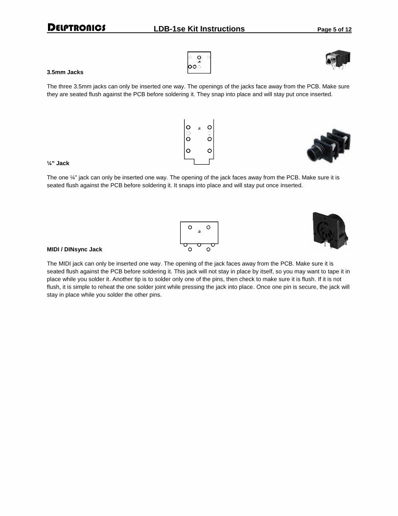
3.5mm Jacks
The three 3.5mm jacks can only be inserted one way. The openings of the jacks face away from the PCB. Make sure
they are seated flush against the PCB before soldering it. They snap into place and will stay put once inserted.
¼" Jack
The one ¼" jack can only be inserted one way. The opening of the jack faces away from the PCB. Make sure it is
seated flush against the PCB before soldering it. It snaps into place and will stay put once inserted.
MIDI / DINsync Jack
The MIDI jack can only be inserted one way. The opening of the jack faces away from the PCB. Make sure it is
seated flush against the PCB before soldering it. This jack will not stay in place by itself, so you may want to tape it in
place while you solder it. Another tip is to solder only one of the pins, then check to make sure it is flush. If it is not
flush, it is simple to reheat the one solder joint while pressing the jack into place. Once one pin is secure, the jack will
stay in place while you solder the other pins.
LDB-1se Kit Instructions Page 6 of 12
Top Side Components
The pushbuttons, LEDs, and potentiometer are mounted on the top side of the PCB, the opposite side that all the
other parts are on. Refer to the photo of the completed kit for reference.
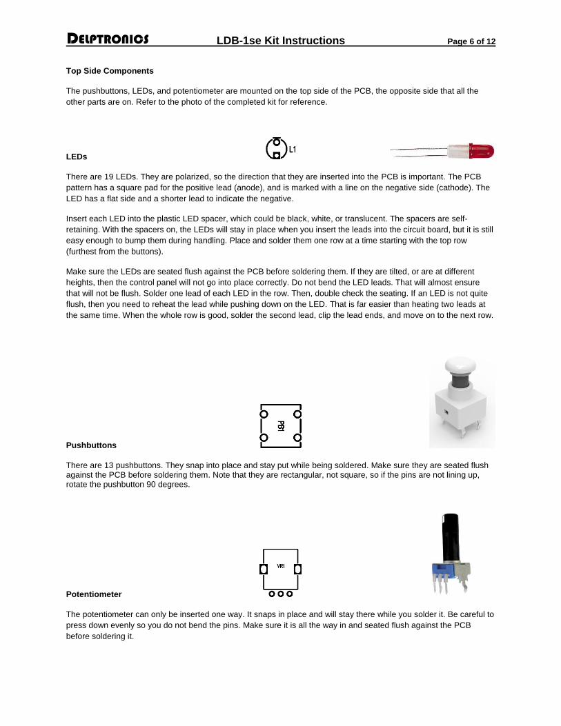
LEDs
There are 19 LEDs. They are polarized, so the direction that they are inserted into the PCB is important. The PCB
pattern has a square pad for the positive lead (anode), and is marked with a line on the negative side (cathode). The
LED has a flat side and a shorter lead to indicate the negative.
Insert each LED into the plastic LED spacer, which could be black, white, or translucent. The spacers are self-
retaining. With the spacers on, the LEDs will stay in place when you insert the leads into the circuit board, but it is still
easy enough to bump them during handling. Place and solder them one row at a time starting with the top row
(furthest from the buttons).
Make sure the LEDs are seated flush against the PCB before soldering them. If they are tilted, or are at different
heights, then the control panel will not go into place correctly. Do not bend the LED leads. That will almost ensure
that will not be flush. Solder one lead of each LED in the row. Then, double check the seating. If an LED is not quite
flush, then you need to reheat the lead while pushing down on the LED. That is far easier than heating two leads at
the same time. When the whole row is good, solder the second lead, clip the lead ends, and move on to the next row.
Pushbuttons
There are 13 pushbuttons. They snap into place and stay put while being soldered. Make sure they are seated flush against the PCB before soldering them. Note that they are rectangular, not square, so if the pins are not lining up, rotate the pushbutton 90 degrees.
Potentiometer
The potentiometer can only be inserted one way. It snaps in place and will stay there while you solder it. Be careful to
press down evenly so you do not bend the pins. Make sure it is all the way in and seated flush against the PCB
before soldering it.

LDB-1se Kit Instructions Page 7 of 12
Battery Snap
The battery holder wires are first threaded up through the hole next to the battery
pads, arched over, then soldered in place on top of the board. This keeps the battery
wires from getting accidentally pulled out of the PCB. The red (positive) wire goes in
the hole with the square pad, and the black (negative) wire goes in the hole with the
round pad.
Chips
There are six chips. Carefully insert each chip into its appropriate socket, making sure
not to bend any of the pins. Note the direction of the chips before inserting them. The
notch on the chip must line up with the notch on the socket. Refer to the photo of the
completed kit for reference.
The chip pins come from the factory a little bit splayed out, not pointing straight down.
You may need to bend them inward a little before you insert them. Hold the body of
the chip and rest all of the pins on one side against the table top and gently press
down just a little bit. Then do the other side. If the pins do not line up well with the
socket, repeat the straightening procedure.
Value Pins Quantity Refdes TL072 8 2 U1, U3 TL074 14 1 U2 NoiseChip 8 1 U4 will be marked PIC12F1822 or PIC12F1571 TC1044 8 1 U5 PIC18F26K40 28 1 U6 6N138N 8 1 U7

LDB-1se Kit Instructions Page 8 of 12
Inspection
At this stage, pause to inspect your work. Compare your PCB to the photo. Make sure that:
• You didn’t forget a part.
• The chips are oriented correctly.
• All of your solder joints are good.
• There are no solder bridges (blobs of solder covering two leads/pins).
• The leads are clipped off short – right above the solder.
• The bottom side parts are seated flush against the PCB.
Test
1. Insert a new 9V battery in the battery clip and turn on the LDB-1se. The first time you turn it on, you will see the
two Row Indicator LEDs blinking alternately for about two seconds. Subsequent power on cycles will show an
animation of all of the LEDs on the unit. If you do not see the LEDs blinking, then something is wrong. Turn off
the LDB-1se, remove the battery and reinspect your work. Otherwise, go to the next step.
2. Insert a mono ¼" plug into the audio output jack and plug the other end of the cable into your amplifier or mixer.
3. The LDB-1se starts in the “Pad Play” mode. Press the buttons along the bottom of the LDB-1se to play individual
drum sounds. If you do not hear some or all of the sounds, or if an instrument sounds odd, then something is
wrong. Turn off and unplug the LDB-1se and reinspect your work.
4. If you have gotten this far, then you should be good to go. Of course, you will want to test all of the other
functions at some point to be certain that everything is soldered correctly.
5. You have successfully built an LDB-1se Analog Drum Machine. Congratulations!
Control Panel, Battery Holder, and Feet
The panel covers most of your soldering, so it is best to test the LDB-1se before putting the
panel on. First, attach the battery holder to the bottom of the panel with the two small screws
and nuts, as shown in the picture to the right.
Next, attach the plastic feet and spacers to the PCB. Then put the control panel on, and screw it
to the spacers, as shown below.

LDB-1se Kit Instructions Page 9 of 12
Bottom / Component Side of Circuit Board

LDB-1se Kit Instructions Page 10 of 12
Top / Controls Side of Circuit Board

LDB-1se Kit Instructions Page 11 of 12
Bill of Materials
Name Value Quantity RefDes
Diode 1N4148 26 D1 - D9, D11 - D27
Schottky Diode BAT85 1 D10
Resistor 22R 2 R70, R76
Resistor 220R 4 R38, R46, R48, R67
Resistor 390R 1 R6
Resistor 470R 2 R33, R68
Resistor 560R 1 R9
Resistor 820R 1 R35
Resistor 1K 12 R40, R44, R50, R61, R62, R63, R64, R65, R66, R69, R73, R75
Resistor 1K5 1 R54
Resistor 2K2 1 R56
Resistor 4K7 3 R25, R60, R74
Resistor 6K8 1 R57
Resistor 7K5 1 R22
Resistor 10K 10 R18, R28, R36, R41, R45, R51, R58, R59, R71, R72
Resistor 15K 2 R26, R52
Resistor 22K 2 R7, R14
Resistor 33K 5 R13, R17, R20, R21, R31
Resistor 47K 1 R27
Resistor 68K 2 R24, R29
Resistor 82K 1 R8
Resistor 100K 9 R1, R2, R3, R4, R19, R32, R37, R42, R53
Resistor 220K 3 R11, R15, R47
Resistor 390K 3 R5, R12, R16
Resistor 1M 3 R30, R34, R55
Resistor 2M2 3 R10, R23, R39
Resistor 4M7 2 R43, R49
Capacitor Ceramic 220 pF 1 C24
Capacitor Ceramic 470 pF 3 C14, C15, C16
Capacitor Ceramic 0.0010 uF 4 C8, C18, C19, C23
Capacitor Ceramic 0.0022 uF 1 C20
Capacitor Ceramic 0.0033 uF 2 C9, C10
Capacitor Ceramic 0.0068 uF 2 C28, C29
Capacitor Ceramic 0.022 uF 2 C32, C33
Capacitor Ceramic 0.033 uF 6 C26, C27, C30, C31, C35, C36
Capacitor Ceramic 0.047 uF 1 C11
Capacitor Ceramic 0.10 uF 10 C1, C2, C3, C4, C5, C6, C7, C22, C25, C38
Capacitor Ceramic 0.22 uF 1 C34
Capacitor Ceramic 0.47 uF 2 C13, C21
Capacitor Ceramic 1 uF 3 C12, C17, C37

LDB-1se Kit Instructions Page 12 of 12
Bill of Materials (continued)
Name Value Quantity RefDes
Capacitor Electrolytic 10 uF 4 C39, C41, C42, C43
Capacitor Electrolytic 100 uF 1 C40
NPN Transistor 2N3904 9 Q1, Q2, Q3, Q4, Q5, Q6, Q7, Q8, Q9
5V Regulator LM7805 2 REG1, REG2
Optoisolator 6N138 1 U7
NoiseChip PIC12F1571 1 U4
MCU PIC18F26K40 1 U6
Charge Pump TC1044 1 U5
OpAmp TL072 2 U1, U3
OpAmp TL074 1 U2
LED 19 L1 - L19
Tempo 10K 1 VR1
1/4 Mono Jack Audio Out 1 J1
3.5mm Mono Switched Jack
Clock In 3 J4, J5, J6
DIN5 MIDI/DINsync 1 J3
TypeMJack Power 1 J2
Tactile Switches 13 PB1-13
Switch SPST 1 SW1
Switch Cap
1
9V Battery Snap
1
Battery Holder Vertical
1
LED Standoffs
19
PCB Standoffs (set)
1
pcb
1
panel
1