lean workstation design process...
TRANSCRIPT

(Woolson & Husar, 2004)
Lean Workstation Design Process
Master of Science Thesis in the Master Degree Program Production Engineering
CHRISTER ERICSSON
JOAKIM HELDMANN
Department of Product and Production Development Division of Production Systems CHALMERS UNIVERSITY OF TECHNOLOGY Gothenburg, Sweden, 2013 Master’s Thesis 2013
i
MASTER’S THESIS 2013
Lean Workstation Design Process Master’s Thesis in Production Engineering
CHRISTER ERICSSON
JOAKIM HELDMANN
Department of Product and Production Development
Division of Production Systems
CHALMERS UNIVERSITY OF TECHNOLOGY

ii
iii
SAMMANFATTNING
Keywords: Lean, Ergonomi, Arbetsplatsdesignprocess, Operatör
Detta examensarbete på mastersnivå syftar till att undersöka vilka arbetsplatsdesignprocesser som existerar i ett stort lastbilstillverkningsföretag i Sverige. Tre olika produktionsanläggningar inom lastbilstillverkningsföretaget utvärderades tillika två produktionsanläggningar tillhörande en svensk biltillverkare. Denna rapport ger läsaren en ökad förståelse av standardiserade processer och standardiserat arbete och varför dessa är nödvändiga för att uppnå ständiga förbättringar i en organisation. Idag så byggs många arbetsstationer bara på en gissning utan att mycket eftertanke har skett, arbetsstationen byggs oftast också med fokus på teknisk genomförbarhet. Detta examensarbete kommer förhoppningsvis att fungera som en väckarklocka för industrin, så att den inser just hur viktigt det är att ha en standardiserad process vid framtagning av nya arbetsstationer. Om operatören är satt i fokus under framtagningen av nya arbetsstationer så kan en bättre arbetsmiljö för operatören uppnås, vilket i sin tur kan ha en rad positiva bieffekter, så som, högre produktivitet, minskad sjukfrånvaro och bättre arbetsmoral bland arbetstagarna tack vara högre egenkontroll. Enligt Lean-‐filosofin ska operatören vara i fokus, med kravet att hen bara ska utföra värdeskapande arbete. Och tack vare ett klart fokus på ergonomi kan överflödig rörelse/förflyttning minimeras tillsammans med andra former av förluster och därmed ökar den värdeskapande andelen av operatörernas arbete.
Resultatet av detta examensarbete på masters nivå är ett förslag på ett framtida sätt att arbeta inom lastbilstillverkningsföretaget, genom att följa den föreslagna arbetsplatsdesignprocessen. Den föreslagna framtida processen betonar tvärfunktionellt arbete, visualisering, operatörsinflytande och operatörsdeltagande, ergonomi, dokumentation, kommunikation, och reducering av vanliga förluster.

iv
v
ABSTRACT
Keywords: Lean, Ergonomics, Workstation Design Process, Operator
This master’s thesis aims to investigate what workstation design processes exist within a large heavy vehicle manufacturer’s organization in Sweden. Three different truck production plants will be evaluated together with a benchmark of two production plants belonging to a Swedish automotive company. The report will give the reader a deeper understanding of standardized processes and standardized work and why these are necessary to achieve continuous improvements in an organization. As of today, many workstations are just built on a hunch, without much thought put into the workstation design and with a mere focus on feasibility. This thesis will hopefully serve as a wake-‐up call for the industry, so it will come to realize just how important it is to have a standardized process when designing a new workstation. And if the operator is put in focus during the workstation design process, a better work environment can be created for the operator. This in its turn could mean higher productivity for the company and a decrease in sick leaves and a better work morale amongst the employees, due to the employee’s higher involvement in the workstation design process. According to the Lean philosophy the operator should be in focus with the requirement that he or she should perform only value-‐adding work. And by a clear focus on ergonomics, wasted motions can be reduced together with other forms of waste, thereby increasing the value-‐adding proportion of the operators work.
The result of the report is a proposal of a future state of the workstation design process for the truck company’s organization. The future workstation design process puts emphasis on: cross functional team work, visualization, operator involvement, ergonomics, documentation, communication and reduction of common wastes.

vi

vii
ACKNOWLEDGEMENT
This master’s thesis report is the result of a half year of work at one of Sweden’s biggest companies. During this time we had the opportunity to visit many production plants manufacturing trucks or components to trucks, e.g. engines and gearboxes.
Lena and Birgitta have been wonderful to collaborate with at the company. They have supported us in many ways, e.g. helped with administrative tasks so our factory visits were possible without any hassle. We could also share ideas and thoughts with them and receive valuable feedback. They also introduced us to interesting key persons who contributed to the project.
As a startup of this master’s thesis we visited Plant B together with Lena and Birgitta where we met Anders who showed the difference between the old and the new section of the plant. And after some discussions we realized the importance of a proper workstation design process to support the engineers when a workstation is designed. We would like to thank Anders for showing us around and his continued divined interest in our master’s thesis.
We also made some visits to Plant C where we got to see the production line together with Peter who had a lot of interesting comments and took the time to have several meetings with us. In the later visits we got to meet Louisa who showed us a newly designed workstation in the plant. Louisa led us to reflect upon what the operators can contribute with when it comes to the workstation design process.
We also had the opportunity to visit Plant A where Kari welcomed us with open arms and showed us around. We started out by looking at some examples of old work stations and then continued towards the new workstations which were designed using their current project process.
At last we visited one of the leading Swedish car manufacturers where Jan informed us about their processes used when designing a new workstation. This was beneficial to broaden our vision to understand how others companies solved the same challenges.
Our supervisors at Chalmers, Cecilia Berlin and Sandra Mattsson have been of great help to us, mainly because of their excellence in writing, but also because of their expertise in interview techniques and methodology. During our meetings we have had a lot of interesting arguments and much valid thoughts have been added to this report as a product of these meetings. Cecilia Berlin also serves as our examiner.
Göteborg, June 2013
Christer Ericsson & Joakim Heldmann

viii
ix
TABLE OF CONTENTS
1 Introduction .......................................................................................................................... 1
1.1 Company Introduction .................................................................................................. 1
1.2 Background ................................................................................................................... 1
1.3 Problem Definition ........................................................................................................ 2
1.4 Research Questions ...................................................................................................... 2
1.5 Purpose and Goal .......................................................................................................... 2
1.6 Priorities and Delimitations .......................................................................................... 3
2 Methodology ........................................................................................................................ 4
2.1 Research approach ....................................................................................................... 4
2.2 Literature review .......................................................................................................... 5
2.3 Data collection Methods ............................................................................................... 6
2.3.1 Observations ......................................................................................................... 7
2.3.2 Interviews ............................................................................................................. 7
3 Theoretical framework ......................................................................................................... 9
3.1 What is a Process? ........................................................................................................ 9
3.2 Workplace Organization ............................................................................................. 10
3.3 Lean Philosophy .......................................................................................................... 11
3.4 Lean Product Development ........................................................................................ 13
3.5 5S ................................................................................................................................ 14
3.6 7 Wastes + 1 ................................................................................................................ 14
3.7 The 3 M’s – the enemies of productivity .................................................................... 15
3.8 Standardized Work ..................................................................................................... 15
3.9 Sweden’s Changing Demographic Prerequisites ........................................................ 16
3.10 Cross Functional Teams .............................................................................................. 17
3.11 Assembly Ergonomics ................................................................................................. 18
3.12 MATERIALS EXPOSURE AND MATERIALS FEEDING .................................... 22
4 Emperic Study ..................................................................................................................... 25
4.1 Current workstation design process ........................................................................... 25
4.1.1 Mapping of current process ................................................................................ 25
4.2 Conclusion of Emperic Study ...................................................................................... 40
5 Discussion ........................................................................................................................... 44
6 Conclusions ......................................................................................................................... 47
7 Result: Future Workstation Design Process ........................................................................ 49
8 References .......................................................................................................................... 59

x

0
ACRONYMS
3M – Muda, Muri and Mura
AFS – Arbetsmiljöverket författningsamling
AGV – Automated Guided Vehicle
BOP – Bill of Process
CAD – Computer Aided Design
CASA -‐ Company’s AnalysSystem Arbetsmiljö
CCMS – Company Car Manufacturing System
CCM – Company’s Contract Management
CPS – Company’s Production System
CFT – Cross Functional Team
DCN – Design Change Notice
EEM – Early Equipment Management
EME – European Manufacturing Engineer
EML – European Manufacturing Logistics
GMPM – Global Manufacturing Project Management
IEA – International Ergonomics Association
ISGDP – Information System Global Development Process
KPI – Key Performance Indicator
LWDP – Lean Workstation Design Process
PFMEA -‐ Pre Failure Mode Effects Analysis
PMR – Product Modification Request
PPL – Product Planning
Q-‐DCN – Quality Design Change Notice
RFI – Request For Information
RFQ – Request For Quotation
VSM – Value Stream Mapping
WMSD -‐ Work-‐related Musculoskeletal Disorder
WPO – Work Place Organization
WSG – Work Safety Group

1
1 INTRODUCTION
CHAPTER INTRODUCTION
This chapter will introduce the reader to the background of this master’s thesis as well as a description of the purpose and goals of this master thesis, furthermore, the research questions are given and followed by priorities and delimitations of this master’s thesis.
1.1 COMPANY INTRODUCTION
This study is performed at a heavy vehicle manufacturing company in Sweden. The company is one of the leading manufacturers globally, and has production sites at many different locations in Sweden but also on a global basis. Previously, the different business areas within the company have been more or less their own company’s. But with the new global organization they should to as high extent as possible have uniform production system processes. That means that the processes should be standardized. This is of course a question of productivity and profitability and the ability to meet an increasing competition. But if the production sites can make their production processes more uniform, it will increase the possibility to state the right demands specification for product development, but it will also open up for more communication between the plants, which in turn can have a lot of positive side effects such as better assembly procedures where ergonomic aspects can be regarded to a higher extent instead of focusing on, question like; can it be built?
1.2 BACKGROUND
Today a workstation is often built on a hunch, without much thought and effort put into the design, “most workstations just happen” says Lee (Weber, 2005). And often the focus when a new workstation is developed lies on simplifying material feeding, which in many cases can lead to big shelves with pallets. The pallet solution often leads to a bad ergonomic situation for the operator, with a lot of picking activities outside the optimal zone, or the so called green zone (Finnsgård, et al., 2011). A picking activity from a pallet will be more time consuming then a picking activity from a smaller plastic container, according to Finnsgård et al (2011).
However in recent years an ongoing trend has been emerging in the industrialized world, that the workstations should be designed with the operators in focus; hence the workstation should aid the operators to fulfill their assembly task. With the operator in focus studies have shown an increase in value-‐added work, thus none-‐value added work like excessive walking and bad working postures can be decreased or in the best case eliminated.
Without a common workstation design process the quality of the workstations will shift in the different workstations in the Swedish plants but also on a global basis. Not having a common workstation design process also implies that information sharing and communication amongst the plants will be harder than it should be which in its turn will have some negative side effects. For instance, one plant might design a new workstation that already exists at another plant, since solutions to problems were not shared amongst the plants, which of course costs time and money.
This thesis project aims to put the operator in focus when a new workstation is designed. According to the Lean philosophy the operator should be in focus with the requirement the he or she should perform only value-‐adding work. Recent studies have shown that, by replacing the pallet storage facades along the workstation to gravity flow racks with smaller plastic
2
containers the picking time could be reduced together with the floor space utilization. The bad work postures could also be minimized since more of the material could be stored in the green zone (Finnsgård, et al., 2011). Thus, the value-‐adding work of the operator will increase.
Recent research of the Swedish demographic developments shows that the population grows older and the importance of rapidly integrating immigrants coming to Sweden gets more and more imperative in the coming decades to ensure the continued growth of the Swedish economy. If the operator is in focus during the workstation design process, the company will be able to recruit from a bigger portion of the working age in Sweden, hence the workstation must allow greater deviation in anthropometric properties together with increased language support.
1.3 PROBLEM DEFINITION
In Swedish industry the workstations are usually not designed from an operator’s perspective, but rather focused on the technical feasibility of the workstation. To achieve higher competitiveness there is a need to reduce obstacles that hinder the operators and to support the operators to carry out their work efficiently and effectivly. The studied company is working towards becoming Lean and a crucial step on the journey is to create standardized and structured processes that puts the operator in focus.
1.4 RESEARCH QUESTIONS
• Is there a common workstation design process within the company’s truck organization?
• How does the workstation design process work today in the different plants? • Which actors are involved in the workstation design processes? • What different aids are available throughout the workstation design process? • What are the limitations of the workstation design process as of today? • Which KPI:s are measured on the workstation? Safety, Quality, Delivery, OEE, 3M
(Muri, Mura, Muda) etcetera?
1.5 PURPOSE AND GOAL
The purpose of this thesis is to map what formal and informal design processes that exist within the truck company’s organization regarding workstation design and investigate to what extent they are followed and if not, why they are not followed. The goal is to propose a structured Lean Workstation Design Process where the operator is put in focus, but also to produce a flowchart of the workstation design process that is easy to grasp. The studied company is to be considered as the main stakeholder and on a lower level the production engineers who work with the design of the workstations in the local plants.
3
1.6 PRIORITIES AND DELIMITATIONS
Assessment of workstations will be within a large Swedish heavy vehicle manufacturer’s truck organization. The length of the study is 20 weeks; start date is set to 2013-‐01-‐21. The workstation should be treated as a product that fits the operator needs and ease performing the work task assigned. The aim is not to, in detail explain every step in the design process, but instead suggest a work order, a process to follow, when cross functional team designs a new workstation. The scope of the study is limited to workstations with an operator or several operators performing assembly tasks.
4
2 METHODOLOGY
CHAPTER INTRODUCTION
This chapter describes the methods used throughout the master’s thesis work. This chapter briefly describes the research approach as well as briefly describing different ways to observe people at work.
2.1 RESEARCH APPROACH
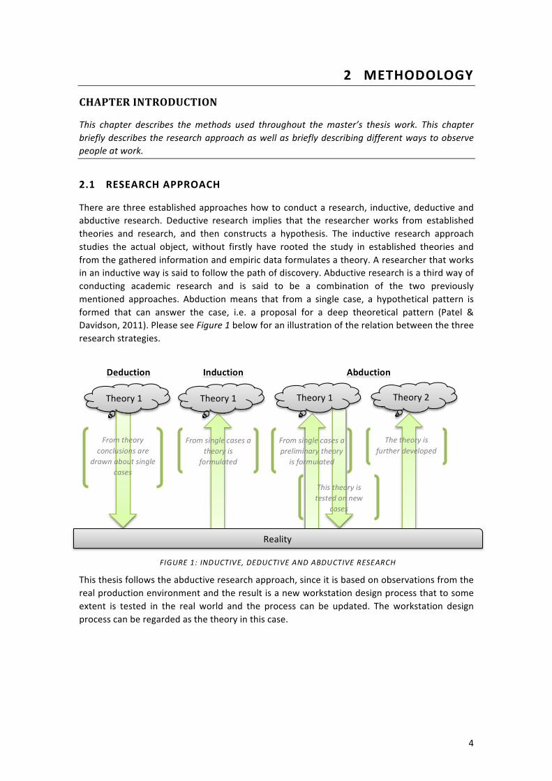
There are three established approaches how to conduct a research, inductive, deductive and abductive research. Deductive research implies that the researcher works from established theories and research, and then constructs a hypothesis. The inductive research approach studies the actual object, without firstly have rooted the study in established theories and from the gathered information and empiric data formulates a theory. A researcher that works in an inductive way is said to follow the path of discovery. Abductive research is a third way of conducting academic research and is said to be a combination of the two previously mentioned approaches. Abduction means that from a single case, a hypothetical pattern is formed that can answer the case, i.e. a proposal for a deep theoretical pattern (Patel & Davidson, 2011). Please see Figure 1 below for an illustration of the relation between the three research strategies.
This thesis follows the abductive research approach, since it is based on observations from the real production environment and the result is a new workstation design process that to some extent is tested in the real world and the process can be updated. The workstation design process can be regarded as the theory in this case.
Reality
Theory 1 Theory 1 Theory 2 Theory 1
From theory conclusions are
drawn about single cases
From single cases a theory is
formulated
From single cases a preliminary theory
is formulated
This theory is tested on new
cases
The theory is further developed
Deduction Induction Abduction
FIGURE 1: INDUCTIVE, DEDUCTIVE AND ABDUCTIVE RESEARCH
5
2.2 LITERATURE REVIEW
“…In writing the literature review, your purpose is to convey to your reader what knowledge and ideas have been established on a topic…” (Procter, 2013)
The performed literature review can be divided into three different phases, study of internal company documents, external literature, and methodology literature.
2.2.1 PHASE ONE OF THE LITERATURE STUDY
Phase one of the literature study was initiated early on in the project to enable the researchers to identify which policy documents that existed within the truck organization regarding workstations. The documents were then studied in correlation with the Swedish agency for workplace-‐related issues’ publications. It was then possible to see which aspects that were highlighted in the company’s documents. Different internal documents from another truck manufacturer that is owned by the company were also examined. The documents from the second truck manufacturer mostly described different ergonomic assessment criterias. The study was also performed to find out if any formal workstation design processes existed in the truck organization at this time. The searches were conducted in the company’s internal information system. In the litterature study the researchers could not find any formal design processes for workstations, merely regulations and assessment forms for already built workstations.
2.2.2 PHASE TWO OF THE LITERATURE STUDY
Phase two of the literature study sought to give the researchers a broader picture of what adequate methods exist to perform interviews both in a structured and unstructured manner, as well as different data collection methods and research methodology. Patel et al (2011) give a concrete tutoring in how to plan, do, and report research. Patel et al. give examples of when to use an inductive research approach or a deductive approach. The book also offers great explanation to other complicated terms e.g. quantitative and qualitative and other data collection techniques. The authors moreover discuss terms such as Hypothesis and theory. The summarization of the literature on data collection methods are available in the data collection methods chapter, whilst the research approach is available in the beginning of this chapter under research approach.
2.2.3 PHASE THREE OF THE LITERATURE STUDY
Phase three of the literature study aimed towards investigating what publications existed within the areas of Lean Manufacturing (Lean assembly station, Lean operator, Lean product development), workstation design, human centered design, facilities planning, Sweden’s demographic situation, materials exposure, materials feeding, cross functional teams, workplace organization, and what a process is. The research was carried out with help of Chalmers Library, both online and printed books, together with internal company documents and doctoral theses available in the office. The findings of phase two of the literature review are summarized in the theoretical framework.

6
2.3 DATA COLLECTION METHODS
To gather information about all parts of a human technology system or work environment, data collection methods are used. This involves such aspects as what people are thinking, doing, imagining, content of work tasks and a lot more. All parameters in the interaction between humans, technology, environment and tasks can be studied through data collection methods.
There are however many suitable methods available when studying or analyzing people at work and their interaction between people and technology. The goals of these methods are to give support and guide the researcher with e.g. data collection, data processing, development of new products, systems and environments and presentation of results (Bohgard, et al., 2009). Some of these methods have several purposes whilst others have been developed just for a single purpose. Therefore it is necessary to combine different methods to achieve a gratifying result. Some combinations of methods are not possible, due to the interference between their properties, for example an objective data collection cannot give qualitative results (Bohgard, et al., 2009)
The methods can be characterized by their properties and divided into four categories.
• Empirical or analytical, depending on the origin of the collected data. • Objective or subjective, depending on the type of collected data. • Quantitative or qualitative, depending on the type of results. • Expert or participative, depending on the degree of user involvement.
In an empirical study the goal is to investigate the person who carries out tasks and handle products, e.g. operating a pneumatic screwdriver or how the operator interacts with a given user-‐interface. It is possible to conduct an analytical study on the same tasks, but then there is no need for the operator to be present. The analytical study is performed by someone with understanding of the domain and knowledge of a specific area, say, ergonomics and design (Bohgard, et al., 2009). Of course there is an advantage if the evaluators have user experience of the task or an actual user is included in the data collection process.
Objective data is collected by direct measurements, e.g. number of times an operator lifts one tool during a day. Objective data collection does not take into account what the operator experiences and feels during the operation. Subjectively collected data can be obtained from the user experience of performing a task, through interviews or other methods. Objective data and subjective data may be combined to obtain a broader result, e.g. the objective data can give you the force required to lift a package but it will not give you the fitness level of the worker. Therefore it is necessary to use subjective data as well.
Quantitative research implies measurements of the collected data i.e. statistical methods and different analyzing methods. Quantitative results are often presented as direct figures (Bohgard, et al., 2009). Qualitative is such research that focuses on “soft” data e.g. interviews and interpretive analyses, usually verbal analyses of text material (Patel & Davidson, 2011). It tends to bring an understanding of the surrounding world in form of words and images. The result cannot be analyzed, at least with stastistical methods, and typically answers questions such as what, who, how, where and when. With qualitative research it is important to keep in mind that the researcher may influence the result by their presence, for example an interview respondent is affected by the person asking the questions (Bohgard, et al., 2009).
7
In all studies there is different involvement from the people being studided. In some cases the user themselves control and implement the data collection, these studies where the people being studided actively contribute to the data collection and analysis are called participative in method. A method where the researcher controls the data collection and what to study is known as an expert method. Most of the methods are done by experts but some have participative elements as well. Thus, it is most common for the researcher to control the implementation and the user to act as a source of information (Bohgard, et al., 2009).
2.3.1 OBSERVATIONS
Observation is a study of a human being in action, consisting of receiving knowledge of the outside world through senses or using scientific instruments to record data. Observation is an objective method of gathering information on how people behave in different situations or in an actual event of interest (Yount, 2006). The purpose of the observer is to achieve an understanding of the user situation without affecting the ongoing process (Bohgard, et al., 2009). Through observation it is easier to obtain knowledge about the human behavior that the observed are not always aware of themselves, therefore they might be hard to gain through interviews. Thus, observations does not represent feelings, attitudes or desires, but it is good at finding out what people actually are doing rather than what they say they are doing. Observations can either be direct or indirect, in an actual work environment or in an artificially constructed environment like a laboratory. An unsystematic observation means that nothing in particular is being studied, everything of interest is noted while systematic observations follow a schedule, widely used when the observer already knows what events or behavior will provide relevant data (Bohgard, et al., 2009).
2.3.2 INTERVIEWS
An interview is a multifaceted method as it can be used as a data collection method in a range of different situations. Interviews are used to gather information about what people are thinking and imagining, and knowledge is obtained about peoples experience, observations, values and dreams. They also provide an understanding of how people reason (Bohgard, et al., 2009). Interviews can be designed in numerous ways, their content and form may vary depending on the subject. Most of the data collected is classified as qualitative but it can be possible to obtain quantitative data as well, depending on the structure of the interview. It is possible to divide interviews into three categorise: unstructured, semi-‐structured and structured. If the purpose is to obtain quantitative data, it is preferable to use a structured interview, while an unstructured interview functions best when qualitative data is being sought (Bohgard, et al., 2009). Interviews must be planned so the questions asked are relevant for the issue elucidated; it is of great importance for the interviewer to describe the purpose of the interview to the interviewee, how the interview will be documented and how and where the results will be used. The interviewer must keep in mind to not compel an answer e.g. not to talk too much, put in words or give their own opinion on the subject. The purpose decides what form of interview should be used to obtain the sought information. The questions asked should follow a logical order and at the end of the interview a summary should be given. This enables the interviewer to test whether he/she has interpreted the interviewee’s response correctly (Bohgard, et al., 2009).

8
UNSTRUCTURED INTERVIEWS
An unstructured interview, also known as open interview, is based on open questions that give the interviewee an opportunity to freely express their thoughts. The interviewer can still govern the interview towards the areas he/she thinks are of great importance. This is an appropriate interview structure if the interviewer knows what to look for in the answers and it is carried out on a small number of people, but does not really have any deeper knowledge in the domain itself, because there are no guided questions it opens up the possibility to make interesting counter questions or go deeper into a certain area, thus one of the drawbacks with unstructured interviews is that it might be hard to compile and compare the answers due to the open questions (Bohgard, et al., 2009).
STRUCTURED
In a structured interview the interviewer has specified the question before and the interviewee can either answer freely or by selecting an answer from a predefined scale, e.g. if they find their workstation potentially harmful from 1 to 5 where 1 stands for very safe and 5 for extremely dangerous. The outcome of structured interviews provides quantitative data which can easily be analyzed because it can be categorized (Bohgard, et al., 2009). In order to predefine questions the interviewer must have good knowledge within the domain and understanding of the situation. The most structured interview form is a survey, a written questioning with fixed questions (Lantz, 1993).
SEMI-‐STRUCTURED
A semi-‐structured interview is somewhere between a structured and unstructured interview. The interviewer has specified a structure with what areas that will be covered, but can freely choose in what order these question will be asked, because it is a semi-‐structured interview the questioner can ask clever follow-‐ups questions, thus it requires the person asking the questions to have a clear picture of what is important within the subject (Bohgard, et al., 2009).
9
3 THEORETICAL FRAMEWORK
CHAPTER INTRODUCTION
This chapter contains the theoretical framework of this master thesis. Areas such as Lean Philosophy and Lean Product Development are introduced to the reader. This chapter also seeks to give a theoretical introduction to assembly ergonomics and materials exposure, but also to explain what a process is, according to the company. These theories are then complemented with other important theories that helps to anchor this thesis report.
3.1 WHAT IS A PROCESS?
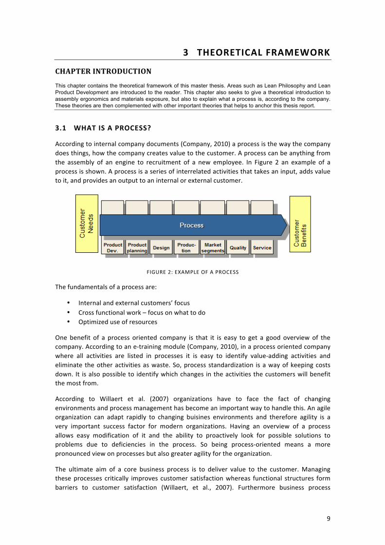
According to internal company documents (Company, 2010) a process is the way the company does things, how the company creates value to the customer. A process can be anything from the assembly of an engine to recruitment of a new employee. In Figure 2 an example of a process is shown. A process is a series of interrelated activities that takes an input, adds value to it, and provides an output to an internal or external customer.
FIGURE 2: EXAMPLE OF A PROCESS
The fundamentals of a process are:
• Internal and external customers’ focus • Cross functional work – focus on what to do • Optimized use of resources
One benefit of a process oriented company is that it is easy to get a good overview of the company. According to an e-‐training module (Company, 2010), in a process oriented company where all activities are listed in processes it is easy to identify value-‐adding activities and eliminate the other activities as waste. So, process standardization is a way of keeping costs down. It is also possible to identify which changes in the activities the customers will benefit the most from.
According to Willaert et al. (2007) organizations have to face the fact of changing environments and process management has become an important way to handle this. An agile organization can adapt rapidly to changing buisines environments and therefore agility is a very important success factor for modern organizations. Having an overview of a process allows easy modification of it and the ability to proactively look for possible solutions to problems due to deficiencies in the process. So being process-‐oriented means a more pronounced view on processes but also greater agility for the organization.
The ultimate aim of a core business process is to deliver value to the customer. Managing these processes critically improves customer satisfaction whereas functional structures form barriers to customer satisfaction (Willaert, et al., 2007). Furthermore business process

10
orientation has been shown to reduce inter-‐functional conflict and increase interdepartmental connectedness and integration, both of which impact long and short-‐term performance.
3.2 WORKPLACE ORGANIZATION
In an article by Anne Grönlund (2007) one’s work influence or control over one’s work is discussed. The study is based on data from European Social Survey (2012). The data is based on a representative selection of the working adult West European population from a large number of countries. Grönlund states some importing findings in the discussion chapter of the article, e.g. that people who have higher control of their own work, more often than others work overtime and to a higher extent perceive that they perform their work at the expense of their family life. From the study, it can be interpreted that their work is harder to delimit both physically and mentally. However other results point against that. If the analysis is delimited to Sweden, no such effects of higher control of one’s own work can be pointed out. More control over one’s work does not increase the Swedes’ tendency to work overtime nor long work weeks. Control over one’s work seems to decrease the conflict between work and family life rather than an increase, which is the case in the other countries.
A workplace where the individuals have high control over their own work is characterized by that the work is developing the individual, the one who performs the work may utilize his or her ideas, and that one can decide how the work tasks should be performed (Eriksson, 2007).
“Det goda arbetet” – The good workplace, became a concept in 1985 in connection with Swedish Metalworkers' Associations congress. The most important parts in the definition were: Work organization for cooperation, participation, professionalism in all work, education as part of the work, equality at the workplace and a working environment without risk to health and without accidents (Håkansson & Isidorsson, 2006). With that said the good workplace is not established at once, it is rather about continuously developing knowledge and increasing competence, which is also considered to counter stress and illness. The number of long-‐term sick leaves and early retirements in Sweden have increased significantly in recent years. The increase began in 1997, and although the trend is broken, illness figures remain high. High workload, low decision latitude and recurrent reorganizations are risk factors, while knowledge about stress problems, wellness activities, social support and opportunities for recovery are highlighted as protective factors.
In a study of illness in municipal workplaces, a picture emerged that repeated reorganizations and change process leadership that is characterized by uncompromising, pseudo-‐democratic processes and ambiguity lead to organizational anxiety and illness (Szücs, 2004). Szücs gives a number of citations from interviews regarding a pseudo-‐democratic reorganization, here freely translated to English: “They listen to the staff but do not hear what they say. Many good suggestions were waved away because the matter was already determined” and "One was promised to be in teams for free thinking and new ideas, but in the end, the management had already decided what the organization would look like". Increased insecurity and increased work intensity are also highlighted by several researchers as having increased in the workplace. These research results further complicate the picture of what a good workplace is. A workplace organization that is characterized by the individual’s high control over the work and large opportunities for independence cannot naturally be regarded as a sustainable workplace organization (Håkansson & Isidorsson, 2006). The challenges lie within remaining agile and continuously developing the personnel’s knowledge and increasing their competence.

11
3.3 LEAN PHILOSOPHY
Lean production is a practice that aims towards maximizing the value-‐added time in production, everything else is considered as waste. Value-‐added time is defined as any action that a customer would be willing to pay for (Roos et al., 1991). The workstation design process customer is the operator who will work at the workstation. The operator has no desire to “pay” for unnecessary work and movement which adds no value to the product. Therefore a workstation designed from a Lean perspective should help the operator to create more value for the end-‐customer with fewer resources. Some common goals within Lean Philosophy are: improve quality, eliminate waste, reduce time and reduce total production cost.
A widely used model within the Lean philosophy is the “4P” model; problem solving, people and partners, process and philosophy (see Figure 3 below).
Continuous improvement and learning is a part of problem solving, one should spend time on the shop floor to thoroughly understand the situation. Only when one fully understands the situation it is possible to find the root cause of the problem; all possible solutions to the problem should be considered thoroughly before they are rapidly implemented (Liker, 2004).
People, partners and suppliers should all be treated with the same respect. By challenging and helping the suppliers, they will become better at what they do. The process step in the “4P” model is about eliminating waste. A process “flow” can be used to detect problems at the production line. A widespread waste is overproduction and uneven workload. Another way to detect problems with production is the use of Jidoka, which means that one should stop the production line when a quality problem surfaces. (Liker, 2004).
Lean philosophy involves long-‐term thinking, even at the expense of short-‐term finical goals. The philosophy can be applied in any environment – blue-‐collar, white-‐collar and manufacturing. Liker states that management can dramatically improve their business process by (Liker, 2004):
• Eliminating wasted time and resources • Building quality into workplace systems • Finding low-‐cost but reliable alternatives to expensive new technology • Perfecting their business process • Building a learning culture for continuous improvements.
FIGURE 3 THE "4P" MODEL (LIKER, 2004)
Problem Solving
People and Partners
Process Philosophy
12
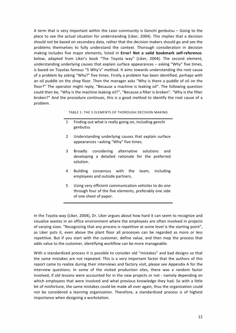
A term that is very important within the Lean community is Genchi genbutsu – Going to the place to see the actual situation for understanding (Liker, 2004). This implies that a decision should not be based on secondary data, rather that the decision makers should go and see the problems themselves to fully understand the context. Thorough consideration in decision making includes five major elements, listed in Error! Not a valid bookmark self-‐reference. below, adapted from Liker’s book “The Toyota way” (Liker, 2004). The second element, understanding underlying causes that explain surface appearances – asking “Why” five times, is based on Toyotas famous “5 Why’s” method. It aims towards understanding the root cause of a problem by asking “Why?” five times. Firstly a problem has been identified, perhaps with an oil puddle on the shop floor. Then the manager asks “Why is there a puddle of oil on the floor?” The operator might reply, “Because a machine is leaking oil”. The following question could then be, “Why is the machine leaking oil?”, “Because a filter is broken”. “Why is the filter broken?” And the procedure continues, this is a good method to identify the root cause of a problem.
TABLE 1: THE 5 ELEMENTS OF THOROUGH DECISION MAKING
1 Finding out what is really going on, including genchi genbutsu
2 Understanding underlying causes that explain surface appearances –asking “Why” five times.
3 Broadly considering alternative solutions and developing a detailed rationale for the preferred solution.
4 Building consensus with the team, including employees and outside partners.
5 Using very efficient communication vehicles to do one through four of the five elements, preferably one side of one sheet of paper.
In the Toyota way (Liker, 2004), Dr. Liker argues about how hard it can seem to recognize and visualize wastes in an office environment where the employees are often involved in projects of varying sizes. “Recognizing that any process is repetitive at some level is the starting point”, as Liker puts it, even above the plant floor all processes can be regarded as more or less repetitive. But if you start with the customer, define value, and then map the process that adds value to the customer, identifying workflow can be more manageable.
With a standardized process it is possible to consider old “mistakes” and bad designs so that the same mistakes are not repeated. This is a very important factor that the authors of this report came to realize during their interviews and factory visit, please see Appendix A for the interview questions. In some of the visited production sites, there was a random factor involved, if old lessons were accounted for in the new projects or not -‐ namely depending on which employees that were involved and what previous knowledge they had. So with a little bit of misfortune, the same mistakes could be made all over again, thus the organization could not be considered a learning organization. Therefore, a standardized process is of highest importance when designing a workstation.
13
As previously mentioned, it is important to think in terms of “who is the customer”, when trying to identify wastes. In this report, the customer is the operator, but also “the stable process” entails that all activities involved in the workstation design process should add value to the operator or the process. Addition in value for the operator is such things that increase the ergonomics, i.e. removal of heavy lifting, reduction of work outside the green zone (the green zone is described in chapter 3.11), reduction of vibrations and so on. Reduction in wasted motion can be considered as value-‐adding to the stable process, and also the upholding of 5S can be regarded as such. With these theories in mind the authors could start designing the Lean Workstation Design Process.
3.4 LEAN PRODUCT DEVELOPMENT
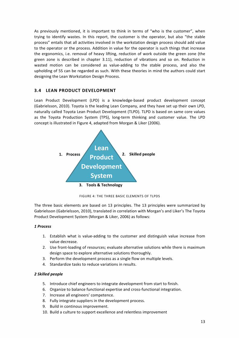
Lean Product Development (LPD) is a knowledge-‐based product development concept (Gabrielsson, 2010). Toyota is the leading Lean Company, and they have set up their own LPD, naturally called Toyota Lean Product Development (TLPD). TLPD is based on same core values as the Toyota Production System (TPS), long-‐term thinking and customer value. The LPD concept is illustrated in Figure 4, adapted from Morgan & Liker (2006).
FIGURE 4: THE THREE BASIC ELEMENTS OF TLPDS
The three basic elements are based on 13 principles. The 13 principles were summarized by Gabrielsson (Gabrielsson, 2010), translated in correlation with Morgan’s and Liker’s The Toyota Product Development System (Morgan & Liker, 2006) as follows:
1 Process
1. Establish what is value-‐adding to the customer and distinguish value increase from value decrease.
2. Use front-‐loading of resources; evaluate alternative solutions while there is maximum design space to explore alternative solutions thoroughly.
3. Perform the development process as a single flow on multiple levels. 4. Standardize tasks to reduce variations in results.
2 Skilled people
5. Introduce chief engineers to integrate development from start to finish. 6. Organize to balance functional expertise and cross-‐functional integration. 7. Increase all engineers’ competence. 8. Fully integrate suppliers in the development process. 9. Build in continous improvement. 10. Build a culture to support excellence and relentless improvement
1. Process
3. Tools & Technology
2. Skilled people Lean
Product Development
System

14
3 The Tools and Technology Subsystem
11. Adapt technology to fit people and processes 12. Align your organization through simple, visual communication 13. Use powerful tools for standardization and organizational learning
3.5 5S
The 5S program is geared towards improving workplace organization and general housekeeping in work areas (Woolson & Husar, 2004). The 5S’s are defined as follow: Sort, Straighten, Sanitize, Sweep, and Sustain, but are sometimes referred to as: Sort, Set in Order, Shine, Standardize, and Sustain. Workplace organization is essential to implementing and maintaining robust processes, because well-‐ordered work areas are necessary for standardizing procedures. Woolson and Husar (2004) exemplify how to get the employees involved by using a customer-‐centered view. “If a customer came into the plant and saw a filthy work area with material laying in unlabeled positions and workers not engaging in standardized processes, what would be their impression of this work environment and of this business?” From this perspective the employees came to realize that it is of high importance to keep a clean and a well-‐organized working environment. “You never have a second chance of making a first impression” (Woolson & Husar, 2004).
3.6 7 WASTES + 1
Toyota has identified 7 types of wastes, but there is also an 8th waste which is included below (Liker & Meier, 2006).
1. Overproduction. Producing items earlier or in greater quantities than needed by the customer. Producing earlier or more than is needed generates other wastes, such as overstaffing, storage, and transportation costs because of excess inventory. Inventory can be physical inventory or a queue of information.
2. Waiting (time on hand). Workers merely serving as watch persons for an automated machine, or having to stand around waiting for the next processing step, tool, supply, part, etc., or just plain having no work because of no stock, lot processing delays, equipment downtime, and capacity bottlenecks.
3. Transportation or conveyance. Moving Work In Process (WIP) from place to place in a process, even if it is only a short distance. Or having to move materials, parts, or finished goods into or out of storage or between processes.
4. Overprocessing or incorrect processing. Taking unneeded steps to process the parts. Inefficiently processing due to poor tool and product design, causing unnecessary motion and producing defects. Waste is generated when providing higher quality products than is necessary. At times extra “work” is done to fill excess time rather than spend it waiting.
5. Excess inventory. Excess raw material, WIP, or finished goods causing longer lead times, obsolescence, damaged goods, transportation and storage costs, and delay. Also, extra inventory hides problems such as production imbalances, late deliveries from suppliers, defects, equipment downtime, and long setup times.
6. Unnecessary movement. Any motion employees have to perform during the course of their work other than adding value to the part, such as reaching for, looking for, or stacking parts, tools, etc. Also, walking is waste.

15
7. Defects. Production of defective parts or correction. Repairing of rework, scrap, replacement production, and inspection means wasteful handling, time, and effort.
8. Unused employee creativity. Losing time, ideas, skills, improvements, and learning opportunities by not engaging or listening to your employees.
3.7 THE 3 M’S – THE ENEMIES OF PRODUCTIVITY
1. MUDA – Non-‐value-‐added operation, the most famous M. Muda includes the eight wastes mentioned above. These are wasteful activities that lengthen the lead times, cause extra movement to get parts or tools, create excess inventory, or result in any type of waiting (Liker, 2004).
2. MURI – Overburdening people or equipment. Muri can be seen as the opposite of Muda to some extent. Muri implies that the machines and/or employees are overburden with tasks to the breaking point, which will result in safety and/or quality problems.
3. MURA – Unevenness. In normal production systems, at times there is more work than the machines and/or the employees can handle and at other times there is a lack of work. Unevenness results from an irregular production schedule or fluctuating production demand due to internal problems, like downtime or missing parts or defects. Unevenness in production means that there will be a need to have personnel and machines for the highest level of production. Mura will thus create Muda (Liker, 2004).
3.8 STANDARDIZED WORK
By documenting the current best practice, standardized work can be seen as the baseline for continuous improvements or kaizen. Standardized work is a way of creating a repeatable work method that can meet the customer’s request. Taiichi Ohno is often quoted as declaring: “Without a standard, there can be no improvement.” (Rosenthal, 2009). As the standard keeps improving, the new standard becomes the baseline for future improvements. The never-‐ending process of improving standardized work prevents from backsliding to the previous state (Lean Enterprise Institute , 2009). The company’s properties of standardized work can be summarized in the following three points which are adapted from the company’s Lean guide lines (Company, 2008).
TABLE 2: THE PROPERTIES OF STANDARDIZED WORK
1 To ensure that safety of shop floor operators
2 To ensure that quality is built into the process
3 To ensure that productivity is achieved
Standardized work which is a part of Lean manufacturing has been introduced as a way to encourage daily improvements; Lean manufacturing proposes that workers on the shop floor make improvements in their work on daily basis. Standardized work consists of three elements (Marksberry, et al., 2011):

16
TABLE 3: THE THREE ELEMENTS OF STANDARDIZED WORK
1 Takt time, which is the rate at which products must be mad in a process to meet customer demand
2 The precise work sequence in which an operator performs tasks within takt time.
3 The standard inventory, including units in machines, required to keep the process operating smoothly.
If the operators make their own work methods or assembly sequences to perform a task it is hard to fulfill the principle of Lean production, since the resulting outcome will be too unpredictable (Whitmore, 2008). With standardized work the abnormalities are brought to the surface and become visible, so the abnormalities can be more easily corrected. A deeper understanding and knowledge of the assembly sequence is needed to find and eliminate the root cause of variability and to resolve work methods-‐related issues.
Standardized work is today an important part of a management system where the workers follow a series of predefined assembly steps. But it is important to not only use standardized work as a documentation tool, but also the work analysis tool it really is. By minimizing the variation and eliminating unnecessary motion wastes can be reduced, problem solving becomes easier and the productivity is enhanced (Marksberry, et al., 2011) (Whitmore, 2008).
3.9 SWEDEN’S CHANGING DEMOGRAPHIC PREREQUISITES
Today people in Sweden tend to live longer and have fewer children. In the last 100 years there has been a dramatic shift in Sweden’s demography. In the year 1900 almost one fourth of the Swedish population was below 10 years old and less than one tenth was over 65 years old (Statistiska centralbyrån, 2013). Today the situation is totally different, the amount of the population over 65 years old has doubled and the amount below 10 years old has been halved, see Figure 5.
FIGURE 5: POPULATION PYRAMID FOR SWEDEN 31ST DECEMBER 1900 AND 2012

17
The demographic effect will in the coming decades impact the Swedish society to a higher extent than any time in the postwar era. The composition of the Swedish population both in terms of age and ethnicity will imply changing prerequisites together with new and more extensive demands within most parts of the Swedish society (Arbetsförmedlingen, 2004). Therefore not only the Swedish labor market’s ability to include immigrants but also the companies’ abilities to provide good workplaces that fits both older people, other cultures and people with language difficulties will be vital to the continued growth of the Swedish economy throughout the coming decades. User-‐centered design and consequently the focus on operators might be one solution to this problem. If the workplace is more including, the company will be able to recruit from a bigger part of the working-‐age population.
3.10 CROSS FUNCTIONAL TEAMS
“A Cross Functional Team (CFT) is simply a team made up of individuals from different functions or departments within an organization” (MindTools, 2013). Teams like this are useful when you need to bring people with different expertise together to solve a problem. Previous research in 1995 showed that in U.S. firms, more than 84% of the most innovative product development projects used CFT (Griffin, 1997) (Holland, et al., 2000). Holland et al. present a table with benefits attributed to cross-‐functional teams, see Table 4. Mind Tools state that the most important distinction between the creation of a cross-‐functional team and the formation of a new department is that members of a cross-‐functional team maintain substantial links to their day-‐to-‐day responsibilities and to managers in their "home" department (MindTools, 2013).
TABLE 4: BENEFITS ATTRIBUTED TO CROSS-‐FUNCTIONAL TEAMS
1 Increase speed
2 Improve ability to handle complexity
3 Foster an entrepreneurial culture
4 Customer focus
5 Enhance creativity
6 Organizational learning
7 Enhance employee motivation
8 Single point of contact
9 Better quality information at higher levels
Table 4 lists the benefits attributed to CFT:s, but there are of course challenges associated with CFT:s as well. Mind Tools lists four challenges which are adapted in Table 5. It is possible to overcome these challenges by setting objectives early on, and by getting your team, and key managers, to agree to them (MindTools, 2013).

18
TABLE 5: CHALLENGES WITH CROSS-‐FUNCTIONAL TEAMS
1 Team members may still be doing their "day jobs," with the same responsibilities, workload, and deadlines as before. This can lead to prioritization issues.
2 People might be reluctant participants, and may not be happy to take on the additional work and effort that being part of a cross-‐functional team often requires.
3 It is more difficult to set priorities, make decisions, motivate people, and manage performance when you do not have direct authority over members of the team.
4 Team members may be required to use a different set of skills in a new environment. For example, a programmer who normally works alone may now be required to work with others.
When forming a CFT there are several important factors to bear in mind. One factor is the selection process -‐ how to select the members of the CFT. It is important not to neglect the abilities the members need to have besides their technical expertise. Does the member need to possess great communication skills? Or will one have to work against tight guidelines? It is also important to be clear about what can be decided in the team and what has already been decided by senior people (Mindtools, 2013).
3.11 ASSEMBLY ERGONOMICS
Ergonomics, also known as human factors, is the scientific discipline concerned with the understanding of the interactions among humans and other elements of a system, and the profession that applies theoretical principles, data and methods to design in order to optimize human well-‐being and overall system performance (International Ergonomics Association, 2000).
As a practitioner of ergonomics -‐ an ergonomists -‐ in assembly related work, one of the main tasks is to plan, design, and evaluate workstations with the operators’ health in focus. The workstations should be compatible with the needs, abilities, and limitations of people (International Ergonomics Association, 2000).

19
Ergonomics can be divided into the three following categories according IEA (2000):
1. Physical Ergonomics Physical ergonomics is related to human anatomical (the structure of the human body), anthropometric (the dimensions of the human body) physiological (study of function in living systems) and biomechanical characteristics. All these areas are concerned within assembly-‐related work. The relevant topics include working postures, materials handling, repetitive movements, work-‐related musculoskeletal disorders, workplace layout, safety and health.
2. Cognitive Ergonomics Cognitive ergonomics is concerned with mental processes, such as perception, memory, reasoning, and motor response, as they affect interactions among humans and other elements of a system. The relevant topics include mental workload, decision-‐making, skilled performance, human-‐computer interaction, human reliability, work stress and training as these may relate to human-‐system design.
3. Organizational Ergonomics Organizational ergonomics is concerned with the optimization of sociotechnical systems, including their organizational structures, policies, and processes. The relevant topics include communication, crew resource management, work design, design of working times, teamwork, participatory design, community ergonomics, cooperative work, new work paradigms, organizational culture, virtual organizations, telework, and quality management.
In the company’s standard for ergonomics there are three different zones that classify whether the working posture is acceptable from an ergonomic viewpoint. The standard itself is based on the AFS regulation from Arbetsmiljöverket (Middelman, 2011).
The green zone, non-‐injurious impact, is the preferred zone to be working inside. The green zone reaches 30 centimeters in front of the body when standing, and it is accepted that within it, repetitive lifting of heavy loads may occur, up to 12 kilograms ten times an hour. Working inside the yellow zone can possibly have an injurious impact depending on number of repetitions or the duration of the posture; the yellow zone reaches 50 centimeters outside the body and in it, it is not allowed to lift as large a load as in the green zone. Working within the red zone for approximately more than two hours a day will have an injurious impact on the operators’ body. Below is a table of the accepted loads to lift and how frequent it is allowed to lift them, as well as a figure displaying the ergonomic zones.

20
TABLE 6: ACCEPTED LOADS WITH REGARD TO REPETITION (COMPANY, 2004).
Lifting zone / weight
Lifting frequency times/hour
1-‐10 10-‐30 30-‐60 60 -‐
12 kg 7 kg 3 kg 2 kg
7 kg 5 kg 2 kg 1 kg
2,5 kg 2 kg -‐ -‐
FIGURE 6: HUMAN DIMENSIONS (COMPANY, 2004)
Ergonomics is closely connected to the performance of the workstation. Anthropometric properties and measurements are important factors to keep in mind when designing a new workstation; the workstation needs to be suitable for at least 90 percent of male and female body sizes (Wojcikiewics, 2003).
A typical workday for an operator involves movements where she or he has to reach for material, possibly up high and down low, or using twisting motions, for example when tightening screws. These motions may put a lot of tension on the human back and joints if repeated over time. If the workstation has been designed from an operator’s perspective all the material and tools used during a work shift should be placed inside the comfort zone to aid the operator to work as efficiently as possible. To ease this process there are some golden rules to follow, i.e. the material most frequently used should be placed as close as possible to the operator (Finnsgård, et al., 2011). Placing the material in a favorable position for the operator will reduce unnecessary wear on the human body, ensuring good ergonomics, and generate increased productivity and safety (Baudin, 2002) (Sigvard, 1994).

21
From an ergonomic viewpoint there are many advantages of placing the material in small containers rather than on large pallets, for example with small containers it is possible to pick material from two containers at a time which is favorable for good ergonomics and performance (Yamashina, 2010). The small containers will also reduce trunk flexion and raised shoulders demands on operators if placed properly inside the green zone on the material façade, thus this requires a well-‐designed material façade. Below are two pictures displaying the different zones from the side-‐view and top-‐view.
FIGURE 7: COMFORT ZONES (COMPANY, 2004)
In an assembly process there are different ways to present the tools to the operator, for example either the tools can be located on a shadow board or hanging from the ceiling. Usually big pneumatic tools are hanging from the ceiling over the operator’s head with some kind of spring back system. This system makes the tool always available for the operator to reach within an arm’s length. It also gives the possibility of making the tools more rigid to remove vibrations and torque transferred on the operator because most of the weight from the tool will be relieved by suspension hanging from the ceiling.
When working with big parts, e.g. air tanks and engines, the operator can easily be put in a situation where she or he has to extend the arms fully to reach on top of the part, or crouch to reach under, and work outside the comfort zone in order to proceed with the assembly sequence (see Figure 8 below). This is not acceptable and can be solved by allowing the part to rotate either manually or autonomously so the operator can work within the comfort zone. In Plant B this has been solved by AGVs that rotate the assembly object so the operator can work more comfortably and not subjecting their body to unnecessary strain.
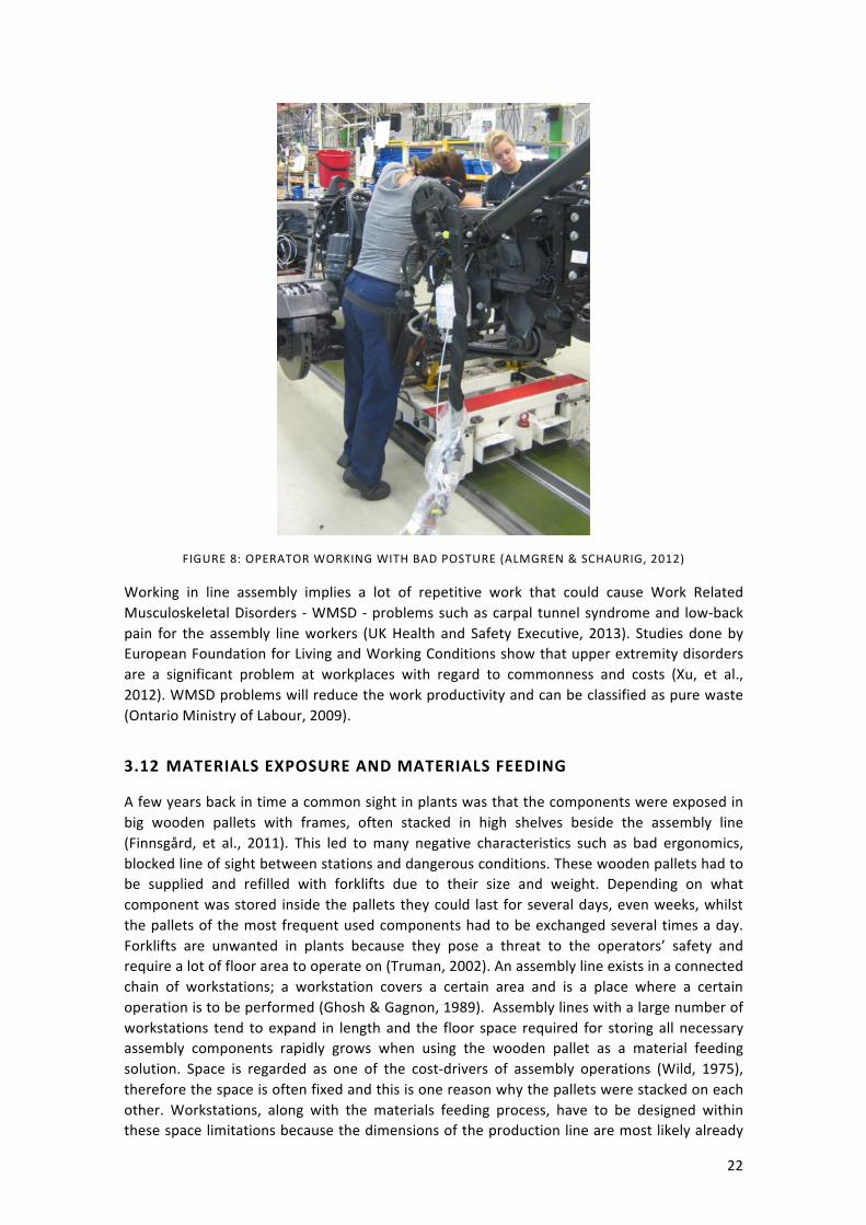
22
FIGURE 8: OPERATOR WORKING WITH BAD POSTURE (ALMGREN & SCHAURIG, 2012)
Working in line assembly implies a lot of repetitive work that could cause Work Related Musculoskeletal Disorders -‐ WMSD -‐ problems such as carpal tunnel syndrome and low-‐back pain for the assembly line workers (UK Health and Safety Executive, 2013). Studies done by European Foundation for Living and Working Conditions show that upper extremity disorders are a significant problem at workplaces with regard to commonness and costs (Xu, et al., 2012). WMSD problems will reduce the work productivity and can be classified as pure waste (Ontario Ministry of Labour, 2009).
3.12 MATERIALS EXPOSURE AND MATERIALS FEEDING
A few years back in time a common sight in plants was that the components were exposed in big wooden pallets with frames, often stacked in high shelves beside the assembly line (Finnsgård, et al., 2011). This led to many negative characteristics such as bad ergonomics, blocked line of sight between stations and dangerous conditions. These wooden pallets had to be supplied and refilled with forklifts due to their size and weight. Depending on what component was stored inside the pallets they could last for several days, even weeks, whilst the pallets of the most frequent used components had to be exchanged several times a day. Forklifts are unwanted in plants because they pose a threat to the operators’ safety and require a lot of floor area to operate on (Truman, 2002). An assembly line exists in a connected chain of workstations; a workstation covers a certain area and is a place where a certain operation is to be performed (Ghosh & Gagnon, 1989). Assembly lines with a large number of workstations tend to expand in length and the floor space required for storing all necessary assembly components rapidly grows when using the wooden pallet as a material feeding solution. Space is regarded as one of the cost-‐drivers of assembly operations (Wild, 1975), therefore the space is often fixed and this is one reason why the pallets were stacked on each other. Workstations, along with the materials feeding process, have to be designed within these space limitations because the dimensions of the production line are most likely already

23
defined (Baudin, 2002). The space needed for materials exposure at a workstation can be calculated from the surface area occupied by the material containers multiplied with the vertical area display facing the assembly line (Finnsgård, et al., 2011).
In Lean production the operator is in focus and should only perform value-‐adding work, from the customer’s perspective (Liker & Meier, 2006) the high material façades with pallets prevents this. Due to the width of the pallets they add unnecessary walking distance for the operator and are ergonomically unsuitable when operators reach into them. A well-‐known problem is that the assembly line and materials feeding processes are rarely designed together, leading to suboptimal performance (Tompkins, et al., 2010). To reduce the walking distance to each container they should be adapted to the size of the components inside. The containers holding the parts most frequently used should be placed in the green zone to ensure optimal work conditions for the operator.
FIGURE 9. CASA STANDARD FOR MATERIAL FACADE
The material should be stored inside plastic containers, each containing a single part variant or a complete assembly kit. A preferable way to store the plastic containers is gravity flow racks. They have proven to be an efficient way to expose material to the operator. In the article “Impact of materials exposure on assembly workstation performance” by (Finnsgård, et al., 2011) this method showed good outcome. The floor space required for storing the material was reduced by 67% and the walking distance was reduced by 52% in comparison with using pallets. Another great benefit with gravity flow racks is that the items are picked from the front and stocked from the rear, resulting in that both operations can be performed without interference. The material will always be within reach for the operator and it is easy to control the inventory since the parts are fully visible at all times. Flow racks are built upon modules which makes them very adaptable to different scenarios. Below is a picture of a gravity flow rack with knuckled shelf and return path on top.
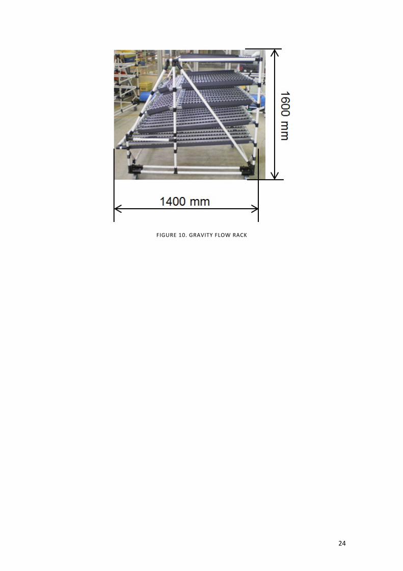
24
FIGURE 10. GRAVITY FLOW RACK

25
4 EMPERIC STUDY
CHAPTER INTRODUCTION
This chapter contains a brief introduction to the company and the whereabouts of its production sites, together with a description of the current workstation design process at the visited production plants. In this chapter the current workstation design processes are mapped, to give the view a good overview of how it works at the different production sites.
4.1 CURRENT WORKSTATION DESIGN PROCESS
What the researchers found out during this study was that in some of the production sites there was no formal workstation design process. Instead the production sites had an informal process that could vary quite a lot depending on whom the researchers talked to. This could of course work well depending on what actors are involved in the process. But certain risks can also be identified. The outcome of the “process” is highly dependable on which actors that are involved and their previous knowledge. For instance a workstation may be built at a production site, but after some time the line technician comes to realize that the ergonomic solution is inadequate and the sick leaves are increasing among the operators. If there is no formal process to handle this design mistake it might risk to fall into oblivion, thus the same mistake can be made again.
The researchers visited three of the company’s production sites in Sweden (Plant A, Plant B and Plant C), and one production site of an automobile manufacturer that works with final assembly (Plant D). Furthermore the researchers had the opportunity to expand the research abroad to investigate the process at one of the company’s production sites in France (Plant E) via virtual meetings, since the plant was occupied with the implementation of a new model at the production line. The production systems are differently designed in the various plants, since they manufacture different products. Plant A is for instance a gearbox supplier for Plant C, and Plant B delivers engines to Plant C. Whereas Plant C works as final assembly for the heavy vehicles. Plant E works similarly to Plant C with final assembly.
4.1.1 MAPPING OF CURRENT PROCESS
The mapping of the current workstation design processes has been conducted partly by literature studies of internal documentation existing within the company, and through interviews with employees with different operating roles at several different production sites. Please see Appendix A for the interview questions. The interview process and its structure are further described in the methodology chapter of this thesis.
PLANT A
In Figure 11 the current process at Plant A is illustrated. The process description was developed by the authors based on the recordings with the interviewee at Plant A together with observations at the factory visit of Plant A. The interviewee at Plant A works as a production engineer and has high knowledge of the different processes that exist in the plant, and the interviewee had also been involved in the extensive redesigns of the plant. It became clear that there existed a lot of visions of future improvements. Plant A had also embraced the Lean philosophy to quite a high extent, which was evident in many ways; for example, they included the operators in the ongoing improvement work, and also sought to continuously reduce wastes in their production system.

26
CROSS FUNCTIONAL TEAM
There are many interesting factors to consider when studying the process described in Figure 11. Let us start with the Cross Functional Team (CFT) (please see Cross Functional Teams in the Theoretical framework for more information). The CFT could have different setups depending on the extent of the improvement or change, but when it comes to a large scale improvement like redesigning a whole line, the following roles would typically be involved: operators, production engineers, quality engineers, ergonomics representatives or occupational health service representatives, Work Place Organization (WPO) and logistics.
A NEW LINE & A NEW WAY OF WORKING
After the CFT has been put together, the pre-‐study phase of the project is initiated. If it is a new project the CFT will go through current solutions or similar solutions, to identify assembly sequence, workplace design, process balancings, work environment, safety and so on. When the pre-‐study phase ends, a business proposal is drawn up and a Request For Quotation (RFQ) goes out to suppliers, asking them if they are interested in working with Plant A to develop the solution. The CFT naturally also asks the supplier for input on the suggested design solution. When the quotations from the different suppliers are collected they are evaluated and a decision is made of whom to pick. The business case is then presented to management who decide if the improvement will be implemented or not. When the choice is made, and if the improvement is approved, a deeper analysis is made of the design solution including Spaghetti diagrams, 3M analysis, staffing, percentage of work performed in the golden zone, the ability to uphold 5S, etcetera.
When a new line is designed at Plant A, all the previously mentioned actors are called to a meeting where (almost) all parts needed to assemble two different products are gathered and put on a long table. The long table is then divided into different sections, where each section represents a workstation. At the table the CFT can try out different ways to assemble the products, but also identify waste (i.e. wasted motion). Perhaps they find a new way to mount part A on part B, but for instance the quality representatives raise concerns and the CFT has to find another way. This can be a good way to exchange ideas and increase the creativity in the organization, but also to gain acceptance for the projects and enhance employee motivation. Another aspect that is becoming more and more important is visualization. What the CFT realized was that not everybody has the same knowledge of computer programs and 2D layouts, so to enable everybody to take part in the work and be able to contribute they had to find a different way to visualize the product and the way of working. One way of doing this is the previously mentioned example with the long table, but they took it a step further. To explain/visualize to the operators what is regarded as value-‐added, non-‐value-‐added-‐but-‐necessary and non-‐value-‐added work they used magnetic tape with three different colors, green, yellow, and red, and all work elements were taped with a color. Then it became clearer to all involved that the red work elements should be reduced, or in the best case, removed. According to the interviewee, the new line should not have any material delivered in cardboard boxes; instead blue plastic containers will be used. This will reduce the material handling time at the stations together with a reduction in trash. The CFT also got external help in this project with the new line from some Japanese engineers who added some valuable input. The interviewee stated that their solutions were not opposites, but rather quite equal.
27
OPERATORS IN FOCUS & A NEW CULTURE
An important fact to mention is that the operator is in focus during the whole process, which manifests itself in the way that they are present at the CFT meetings; therefore they can to a large extent affect the outcome of the process. But also the fact that ergonomics representatives are involved in the process from the start shows that the company has a big emphasis on ergonomics, thus the operator can be considered to be in focus. The way of working with the magnetic tape and the other visualization efforts in the project with the new line sparked an interest out on the shop floor. At first the interviewee said that the other operators on the floor thought that this was weird, what are they doing? But once they saw the results and that it was possible to affect the outcome and actually influence the workstation design, they too wanted to participate and influence the way of working. Thus a new culture was born.
PROCESSES
VCM and VPS serve as guidelines throughout the workstation design process. From the Early Equipment Management (EEM) process, Plant A created a list of activities. The CFT uses this list when a new project is started. The activities can be of various natures, such as ergonomics, business case, and Muda, Muri, and Mura (see The 3 M’s – the enemies of productivity chapter). The CFT decides which activities to consider, depending on the extent of the project. This list of activities serves as the backbone of the project. One of these activities is to document bad solutions. This is a good way to remember what went wrong, so that they do not get repeated in the future. This is an important part in the organizational learning (see the Workplace Organization chapter).
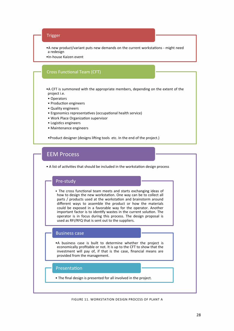
28
FIGURE 11. WORKSTATION DESIGN PROCESS OF PLANT A
• A new product/variant puts new demands on the current workstazons -‐ might need a redesign • In-‐house Kaizen event
Trigger
• A CFT is summoned with the appropriate members, depending on the extent of the project i.e. • Operators • Produczon engineers • Quality engineers • Ergonomics representazves (occupazonal health service) • Work Place Organizazon supervisor • Logiszcs engineers • Maintenance engineers
• Product designer (designs li{ing tools etc. In the end of the project.)
Cross Funczonal Team (CFT)
• A list of aczvizes that should be included in the workstazon design process
EEM Process
• The cross funczonal team meets and starts exchanging ideas of how to design the new workstazon. One way can be to collect all parts / products used at the workstazon and brainstorm around different ways to assemble the product or how the materials could be exposed in a favorable way for the operator. Another important factor is to idenzfy wastes in the current soluzon. The operator is in focus during this process. The design proposal is used as RFI/RFQ that is sent out to the suppliers.
Pre-‐study
• A business case is built to determine whether the project is economically profitable or not. It is up to the CFT to show that the investment will pay of, if that is the case, financial means are provided from the management.
Business case
• The final design is presented for all involved in the project.
Presentazon
29
PLANT B
In Figure 12 the current process at Plant B is described. The process was developed by the authors based on the recordings with the interviewee at Plant B together with observations at the factory visit of Plant B. The interviewee at Plant B works as a production engineer and has high knowledge of the different processes that exist in the plant, and the interviewee was at the time of the interview also involved in an ongoing redesign of a line in the plant. Plant B had also to quite a high extent embraced the Lean philosophy which was expressed in many ways, for example that the operators were given an obvious role in the ongoing improvement work, but they also sought to continuously reduce wastes in the production system. According to the interviewee, factors like ergonomics, wasted motion, process stability, materials exposure and such were always kept in mind when new designs were made.
TRIGGER
The workstation design process at Plant B starts with a trigger, usually that a new product or variant is being introduced at the plant.
CROSS FUNCTIONAL TEAM
A CFT is typically put together with the following actors: operators, safety representatives, production leader, production engineer, production preparer, logistics engineers, packaging engineers and quality engineers. In addition, the production leader, logistics engineers, and packaging engineers are also called to the meeting but they are not always present.
The CFT develops a proposal for a new workstation and produces an economic estimate of how much the new solution would cost to implement. The economic estimate is presented to the steering committee who takes the decision whether it will be implemented or not.
According to the interviewee the operators in the CFT are chosen wisely. All operators do not want to take part in the projects and it is of high importance that it is the right operator that is chosen. The following quote is freely translated from Swedish: “You shall oversee your and your mates’ workstation; you have a responsibility as an operator to speak up and suggest how it should be, but also report the information downstream. If I, as an operator, am uncertain in a situation, I should share and discuss the information with people downstream.” Downstream in this case means the work team back at the plant floor. This operator is also responsible of teaching the new way of working to the rest of the work team, and should also be able to answer why the new design is the way it is. This is an important step to anchor the changes in the organization and minimizing the feeling of “us” and “them”.
CONSIDERATION OF OLD MISTAKES
If a new product was introduced in the plant, but it was similar to an already existing product, the interviewee stated that old lessons learned were considered to a high extent, partly through documentation, and partly by experience. The CFT seeks to find the most experienced operator or other person and asks them for their input. Recently when a new production line was constructed a very experienced operator helped them, and he provided a lot of valid input, according to the interviewee. The documentation could be reject statistics either from internal processes and tests or from external customer’s complaints, which are accessible from a database.
30
MATERIALS EXPOSURE AND PROCESSES
Other support processes used are the GDP, ISGDP and the EEM processes. But overall the workstation design process depends on the CFT to do a good job and how they work in the team is rather informal according to the interviewee. Another important fact to mention is that it is production engineers that decide how the material will be exposed at the production line, e.g. where the material should be placed in the material façade and how the materials are presented. Given that the production engineers follow the logistic guidelines, very similar to the ones used at Plant C (please see the section Plant C for more information regarding the logistical guidelines). The information regarding the materials placement and such are delivered to the logistics department in an informal way, usually through the logistics preparer involved in the CFT.
GOALS
There was no explicit setup of goals before the work started with the new production line at Plant B, besides takt time. The interviewee also added that they have very high quality standards and that there should be zero quality problems with the products and a goal of keeping the cost as low as possible. There are however implicit goals such as good ergonomics and benefits from WPO. Another implicit goal is to keep spaghetti diagrams in mind, in other words consider how the operator will walk at the workstation and thereby minimize wasted motion. The interviewee also pointed out that they tried to avoid open spaces (where dirt can be accumulated) at the workstation to enable 5S. If the operators for example want to have water bottles at the workstation a designated space should exist where their bottles can be stored. Otherwise the overall goal was the feasibility and to create a flow that meets the demand of the set takt time together with high quality standards.

31
“
”
”
“
FIGURE 12. WORKSTATION DESIGN PROCESS OF PLANT B
• A new product/variant puts new demands on the current workstazons -‐ might need a redesign
Trigger
• The extent of the project decides which actors needs to be a part of the Cross Funczonal Team. Below is a list of commonly a}ending actors at Plant B. • Operators • Safety representazves • Produczon leader* • Produczon engineers • Produczon preparer • Logiszcs engineers* • Packaging engineers* • Quality engineers *Called to the meezngs, not always present
Summon actors to form a Cross Funczonal Team
• The technical management group and the assembly management group puts together a quotazon that is presented to the steering commi}ee, the steering commi}ee is also a Cross Funczonal Team, who makes the decision whether the project should be invested in or not.
Budget
• CASA and WPO provides helpful guidelines how the material should be exposed to the operator and clarifies the ergonomics rules that should be fulfilled to ensure good working environment for the operator
CASA and WPO
• Spaghe� diagrams, not formally done, but the minimizazon of unnecessary walking is considered throughout the process • A PFMEA is carried out on the new workstazon design before the workstazon is manufactured to locate possible failures and the reason why it can fail. • Lean philosophy and 5S are used to create a clean and orderly workstazon that enables the operator to fully focus on the assembly task.
Other methods
• A follow-‐up is carried out to check if the workstazon meets the specified targets of the performance indicators. The performance indicators could for example be: produczvity, availability and ergonomics.
Follow-‐up
You shall oversee your and your mates’
workstation; you have a responsibility as an
operator to speak up. And suggest how it
should be, but also report the information
downstream. If I, as an operator, am uncertain in a situation, I should share information with people
downstream.
This operator will have the most knowledge in
that particular workstation and have
the opportunity to educate one’s fellow operators. And report downstream how and why it went the way it did. This is one way to
firmly establish the process in the organization.
32
PLANT C
In Figure 13 the current process at Plant C is described. The process was developed by the authors based on the recordings with the interviewee at Plant C, together with two follow-‐up interviews (transcript of the first follow-‐up available in Appendix B). At the first follow-‐up a representative from the logistics department was present as well, and he provided some valuable additions to the process. At the second follow-‐up interview a local engineer was present who also concurred with the process described in Figure 14. The main interviewee at Plant C has worked as a production engineer and has knowledge of the different processes that exist in the plant, but today the interviewee works as an engineer in the intro engineering department. The intro engineering department are in charge of the workstation design process at an early stage.
WORKSTATION DESIGN PROCESS
The workstation design process at plant C starts with the intro engineering department making a rough article placement of the new articles at the line. Afterwards the information is passed on to local engineers who develop a proposal for article placement, e.g. if they want the article on the right or left side of the materials façade. The logistics department then modifies the article placement with regards to their logistical guidelines. The logistical guidelines include consideration of the green zone (see the section Assembly Ergonomics) both vertically and horizontally, whereas the decision between kitting and batching is made from a logistic-‐economic point of view though with regards of the products quality. For example, there is a guideline stating that if there are more than three variants of an article it should be kitted or sequenced to facilitate for the operator to choose the right article and thereby build in quality robustness in the production system.
COMPARISON BETWEEN PLANT A & PLANT C
The workstation design process at Plant C differs quite a lot from the process at Plant A. Partly because it is mostly informal, partly because it often is initiated by the Global Manufacturing Project Management, and partly because of its pure focus on feasibility, and that the logistics department plays a big role in the design process when it comes to the materials façade design. The operator is not given an obvious role in the process, because of what seems to be internal problems in the organization, such as sick leaves but also that their presence might not be prioritized. The changes that are made to existing workstations are often initiated by the introduction of a new product or an article for a new product variant. According to the interviewee, changes to the workstations are seldom made because of bad ergonomics.
CONSIDERATION OF OLD MISTAKES
The researchers want to point out that there is a risk of not considering old mistakes due to the process being mostly informal. Whether old mistakes are accounted for or not depends on who is involved in the process, and what that person might recall from previous projects. Having a well-‐documented process plays a big part in becoming a learning organization. Plant C now has a new way of working that focuses on describing the best practice, which means that they document the assembly process after it has been modified and save the current best practice in a document template called Process pre-‐requisites. This is a big step in the right direction, since it enables a learning process where old mistakes and good practices can serve as input to the new projects, which the feedback arrow seeks to address in Figure 13.

33
• (P)FMEA is done on the process and product • Ergonomics analysis • VSM
Input
FIGURE 13. WORKSTATION DESIGN PROCESS OF PLANT C
• Global Manufacturing Project Management (GMPM) informs European Manufacturing Engineers (EME) and European Manufacturing Logiszcs (EML) about the new product or variant. • EME and EML gives feedback in form of: Cost & Consequences
Startup meezng
• Intro engineering deparment is in charge • Product Modificazon Request (PMR) -‐ Design Change Nozce (DCN) prepared in SPRINT • Analyses are ready • DCN excel list for parts updated
Rough arzcle placement
• Local engineers are in charge to come up with a proposal to where the material should be placed in the materials facade. • A Quick-‐DCN is prepared in SPRINT • Analyses, balancing and manning are ready • DCN Excel-‐list for parts updated and use points added
Material placement
• Logiszcs department is in charge • Facade layouts in excel ready • Parts updated with Product Placement (PPL) in SPRINT • Parts updated with: sequence / downsize / ki�ng • Parts are placed with regard to ergonomic rules
Modifies the materials placement
• The new workstazon is constructed and introduced to the exiszng produczon line
New Workstazon
• The current process is documented in a process prerequisites document
Process Prerequisites
Sprint Is used for material and resource placement and to some extent also assembly instructions
Excel The local engineer produces an excel sheet with information regarding preferable materials placement
Feedback
34
A NEW LINE & A NEW WAY OF WORKING
On the researchers’ third visit to the plant a local engineer was present as previously mentioned, and a new way of working at Plant C was introduced to the researchers. Plant C had been given the opportunity to try out a new way of designing workstations, and the construction of the new assembly line for new truck cabins was chosen to try out this new way. The new workstation design process is illustrated in Figure 14. A CFT was put together with three experienced operators, one production engineer, one logistics engineer and a Company Production System (CPS) coordinator. The CFT got access to a big open area where they taped out the dimensions of the designated available space in Plant C. Almost all parts that were going to be assembled on the line were presented in the area. Now the operators could start to identify the best way of assembling the cabin. The operators could also to a very high extent decide how the materials should be exposed at the line. The result was a new cabin line without any pallet racks, where all parts where either kitted or sequenced, with the exception of small parts such as screws and nuts. All required work tasks for the operators were now inside the green zone. At normal pace, the new production line would only demand eleven operators whilst the old design methods would require thirteen operators, according to the production engineer. The interviewee said that in the future, the operators would kit or sequence all needed parts in the kit-‐area themselves. By taking back this responsibility to the production department the researchers believe that a higher sense of responsibility can be achieved amongst the operators, since they are responsible for the kits being correctly put together.

35
FIGURE 14. NEW WORKSTATION DESIGN PROCESS OF PLANT C
The work with the new cabin line was a pilot project, but a new pilot project was expected to start in a not so distant future. And if the new project proved to be as successful as the cabin project, this could very likely open up for a new way of doing things at Plant C.
• Design Change Nozce • Quality Design Change Nozce
Trigger
• Operators • Produczon engineers • Logiszcs engineers • CPS coordinator
Summon actors to form a Cross Funczonal Team
• An area is dedicated to devople the new workstazon design, with the same dimensions as in the real plant • The dimensions of the racks, machines and tools are all taped on the floor
Prototype area
Almost all the parts that are going to be assembled are presented at the prototype area
Parts
The operator could now find the best possible way to assemble the product
Assembly sequence
The operators could also to a very high extent decide how the material should be exposed in the material façade
Materials exposure
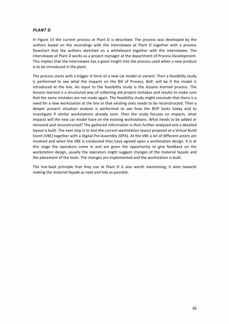
36
PLANT D
In Figure 15 the current process at Plant D is described. The process was developed by the authors based on the recordings with the interviewee at Plant D together with a process flowchart that the authors sketched on a whiteboard together with the interviewee. The interviewee at Plant D works as a project manager at the department of Process Development. This implies that the interviewee has a good insight into the process used when a new product is to be introduced in the plant.
The process starts with a trigger in form of a new car model or variant. Then a feasibility study is performed to see what the impacts on the Bill of Process, BoP, will be if the model is introduced at the line. An input to the feasibility study is the lessons learned process. The lessons learned is a structured way of collecting old project mistakes and results to make sure that the same mistakes are not made again. The feasibility study might conclude that there is a need for a new workstation at the line or that existing ones needs to be reconstructed. Then a deeper present situation analysis is performed to see how the BOP looks today and to investigate if similar workstations already exist. Then the study focuses on impacts, what impacts will the new car model have on the existing workstations. What needs to be added or removed and reconstructed? The gathered information is then further analyzed and a detailed layout is built. The next step is to test the current workstation layout proposal at a Virtual Build Event (VBE) together with a Digital Pre-‐Assembly (DPA). At the VBE a lot of different actors are involved and when the VBE is conducted they have agreed upon a workstation design. It is at this stage the operators come in and are given the opportunity to give feedback on the workstation design, usually the operators might suggest changes of the material façade and the placement of the tools. The changes are implemented and the workstation is built.
The line-‐back principle that they use at Plant D is also worth mentioning, it aims towards making the material façade as neat and tidy as possible.

37
“
• In the feasibility study the impact of the new car model on the Bill of Process (BOP) will be examined
Feasibility study
• The feasibility study concluded that a new workstazon is needed at the the local plant
Trigger: New workstazon
• How does the BOP look today, how does the workstazon look today (if a similar workstazon exists).
Present situazon analysis
• What impacts will the new product have on the workstazon, what needs to be added and what should be removed or re-‐constructed.
Impacts
• The gathered data is analyzed • The detailed layout is analyzed
Analysis
• The suggested layout is tested on a Virtual Build Event (VBE) together with a Digital Pre-‐Assembly (DPA)
Virtual teszng
• A{er the VBE the different actors have agreed on a workstazon design
Workstazon design proposal
• The changes proposed by the operators are implemented on the stazon and the workstazon is built and handed over to the local plant
Implement changes • The operators might have
improvement proposals regarding the material façade, tools and such.
Operators
” “ ”
We build the lines according to the line-‐back
principle. The material façade should be neat and
tidy.
What is the value-‐added time? Build to enable fast
changeovers!
FIGURE 15. WORKSTATION DESIGN PROCESS OF PLANT D AT MANAGEMENT LEVEL

38
In Figure 16 the current process at Plant D at the shop floor level is described. The workstation design process illustrated in Figure 16 below is based on interviews with two local engineers who worked directly with the assembly line. The interviewed engineers worked with CCMS, which is related to CPS. CCMS is inspired by Lean Production and helps the engineers to develop a production system that is lean, flexible and process-‐oriented. Once a week the production engineers and safety representatives meet to discuss problems lifted from the shop floor. If the lifted problem is considered to be of importance, the identified problem is handed over to the production engineering department and together with the equipment technology department they come up with a solution to the identified problem. And if the identified problem is considered to be a big problem for the operators, it is resolved by a temporary fix i.e. an extra operator is placed at the workstation to cope with the situation, or for example a temporary tool, or lifting device, is introduced. At the same time the production engineers are in contact with the management to release money for the project. A RFQ is sent out to the suppliers to see who can deliver the requested solution; the solution is then introduced to the assembly line.
FIGURE 16. WORKSTATION DESIGN PROCESS OF PLANT D AT SHOP FLOOR LEVEL
• A problem is idenzfied at the shop floor, perhaps of an ergonomic nature • The problem is li{ed to the Work Safety Group
Trigger
• The WSG meets once a week to discuss problems li{ed from the shop floor • The WSG consists of representazves from produczon techniques and safety representazves • A decision is made to move forward with the problem and a temporary soluzon is established, perhaps an extra operator is placed at the stazon to ease the situazon
Work Safety Group (WSG)
• The produczon engineering department takes charge over the problem and invites the equipment technology department, who are specialized at technical soluzons and equipment.
Produczon engineering department
• The produczon engineering department and the equipment technology department tries to idenzfy soluzons to the problem. And in parallel to the soluzons progression they try to free up money from the management to finance the project.
Soluzon development in parallel with budget inquiry
• When the produczon engineering department and the equipment technology department have agreed upon a soluzon, a request goes out to the suppliers to see who can deliver the requested product/soluzon.
Inquiry goes out to suppliers
39
PLANT E
The interviewee at Plant E works as a production engineer in the plant. This implies that the interviewee has a good insight into the workstation design process in the plant. The interviewee is also involved in the new production line currently being built.
The new production line is built to be as flexible as possible with open spaces and good visibility. This is accomplished by mounting all equipment in modules hanging from a rectangular steal frame. This means of course less space utilization, but also that the equipment is not fastened in the floor, which means that it is “easy” to rearrange the equipment and to remove and add stations. The operators working at the production line have a large work content, each operator has a work cycle of 15 min (many workstations in one cycle), which means that the operators acquire high knowledge of the assembly procedure and that their work is varying. A downside to the large work content is of course a higher learning threshold, which could make the production process more unreliable if there are many operators on sick leave, but on the other hand each operator will have larger possibilities to cover for another operator on sick leave.
The new production line is built with the line back principle. The line back principle could be summarized into one statement -‐ maximize the value adding time for the operator. And one step towards achieving maximized value-‐adding time for the operator is to expose materials in small quantities at the workstations. In some cases they even managed to get the suppliers to deliver the material directly in the same plastic containers that are to be used at the line, which in its turn removes the additional materials handling otherwise required to move the material from the pallets to the plastic containers. By using the line back principle the material storage is moved back in the organization, which often results in more work for the logistics department. But at the same time the problems with the materials supply and exposure is brought to surface, which is good. Another fact worth mentioning is that the operator does not have to walk to the trash bins to throw packaging or wrapping, it is sent back to the logistics department, where it is handled instead. This makes the assembly process more even and further increases the value-‐adding time for the operators.
The operators are given an obvious role in the workstation design process in plant E, through the “operators in projects” initiative. This implies that the operators’ demands and wishes are heard and taken into account when new workstations are built. However the engineers said that it is important not to use the same operator in too many projects. Since he or she can lose contact with the work team in the line, and become too “like minded” with the production engineers. And it is important to realize that the operator’s role is to stand up for the work team and to anchor the changes in the organization.
The production engineers in the plant stressed the fact that the management had decided that we are going to implement the CCMS principles in the plant; hence the production engineers could emphasize this when implementing the line back principles and the natural arguments that arose with the logistic department.

40
4.2 CONCLUSION OF EMPERIC STUDY
The company should strive towards increasing the collaboration between the plants; and a prerequisite to make this possible is to have common and standardized processes. This will ease the collaboration and communication between the plants. With better communication comes the possibility to share lessons learned and continuous improvements in the workstation design projects. The information gathered from the interviews was compiled into a matrix that made it possible to compare the differences in the workstation design processes at the visited plants. The comparison was done by the researchers without any interaction with the interviewed engineers. The result of the comparison was not communicated back to the engineers that were interviewed because the researchers wanted to have an objective picture. The researches had no connection to the company before this master thesis was carried out. Therefore, the researchers could go in with an open mind and spot the differences between how the different production plants worked; hence the researchers were able to make a fair comparison amongst the plants. The production plants visited during this master’s thesis more or less have their own way of working, thus there are no standardized workstation design process amongst the plants. The comparison presented in Table 7 below, shows that there is no common workstation design process in the company.
TABLE 7. A COMPARISON BETWEEN THE PRODUCTION PLANTS VISITED
Plant A Plant B Plant C old Plant C new Plant D Plant E
1. Present situation analysis
2. Performance indicators
3. Product change trigger
4. Kaizen trigger
5. Cross functional team
6. Physical prototype area
7. Virtual Prototype Area
8. Virtual tools
9. Operator → Assembly sequence
10. CFT → Material exposure
11. PFMEA
12. 5S
13. Follow-‐up
Yes Partly No Uncertain
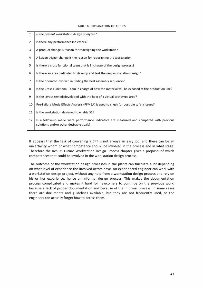
41
TABLE 8: EXPLANATION OF TOPICS
1 Is the present workstation design analyzed?
2 Is there any performance indicators?
3 A product change is reason for redesigning the workstation
4 A kaizen trigger change is the reason for redesigning the workstation
5 Is there a cross functional team that is in charge of the design process?
6 Is there an area dedicated to develop and test the new workstation design?
7 Is the operator involved in finding the best assembly sequence?
8 Is the Cross Functional Team in charge of how the material will be exposed at the production line?
9 Is the layout tested/developed with the help of a virtual prototype area?
10 Pre-‐Failure Mode Effects Analysis (PFMEA) is used to check for possible safety issues?
11 Is the workstation designed to enable 5S?
12 Is a follow-‐up made were performance indicators are measured and compared with previous solutions and/or other desirable goals?
It appears that the task of convening a CFT is not always an easy job, and there can be an uncertainty whom or what competence should be involved in the process and in what stage. Therefore the Result: Future Workstation Design Process chapter gives a proposal of which competences that could be involved in the workstation design process.
The outcome of the workstation design processes in the plants can fluctuate a lot depending on what level of experience the involved actors have. An experienced engineer can work with a workstation design project, without any help from a workstation design process and rely on his or her experience, hence an informal design process. This makes the documentation process complicated and makes it hard for newcomers to continue on the previous work, because a lack of proper documentation and because of the informal process. In some cases there are documents and guidelines available, but they are not frequently used, so the engineers can actually forget how to access them.
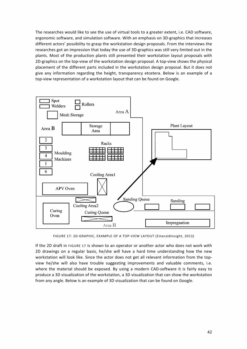
42
The researches would like to see the use of virtual tools to a greater extent, i.e. CAD software, ergonomic software, and simulation software. With an emphasis on 3D-‐graphics that increases different actors’ possibility to grasp the workstation design proposals. From the interviews the researches got an impression that today the use of 3D-‐graphics was still very limited out in the plants. Most of the production plants still presented their workstation layout proposals with 2D-‐graphics on the top-‐view of the workstation design proposal. A top-‐view shows the physical placement of the different parts included in the workstation design proposal. But it does not give any information regarding the height, transparency etcetera. Below is an example of a top-‐view representation of a workstation layout that can be found on Google.
FIGURE 17: 2D-‐GRAPHIC, EXAMPLE OF A TOP-‐VIEW LAYOUT (Emeraldinsight, 2013)
If the 2D draft in FIGURE 17 is shown to an operator or another actor who does not work with 2D drawings on a regular basis, he/she will have a hard time understanding how the new workstation will look like. Since the actor does not get all relevant information from the top-‐view he/she will also have trouble suggesting improvements and valuable comments, i.e. where the material should be exposed. By using a modern CAD-‐software it is fairly easy to produce a 3D visualization of the workstation, a 3D visualization that can show the workstation from any angle. Below is an example of 3D visualization that can be found on Google.
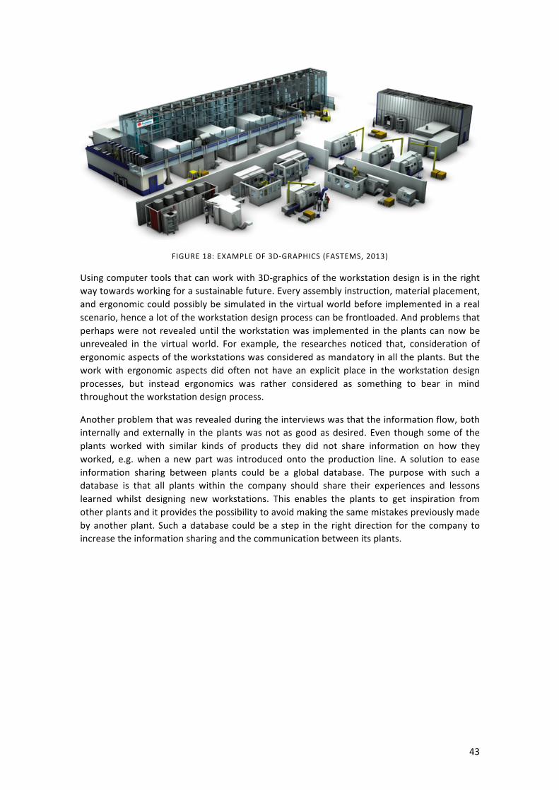
43
FIGURE 18: EXAMPLE OF 3D-‐GRAPHICS (FASTEMS, 2013)
Using computer tools that can work with 3D-‐graphics of the workstation design is in the right way towards working for a sustainable future. Every assembly instruction, material placement, and ergonomic could possibly be simulated in the virtual world before implemented in a real scenario, hence a lot of the workstation design process can be frontloaded. And problems that perhaps were not revealed until the workstation was implemented in the plants can now be unrevealed in the virtual world. For example, the researches noticed that, consideration of ergonomic aspects of the workstations was considered as mandatory in all the plants. But the work with ergonomic aspects did often not have an explicit place in the workstation design processes, but instead ergonomics was rather considered as something to bear in mind throughout the workstation design process.
Another problem that was revealed during the interviews was that the information flow, both internally and externally in the plants was not as good as desired. Even though some of the plants worked with similar kinds of products they did not share information on how they worked, e.g. when a new part was introduced onto the production line. A solution to ease information sharing between plants could be a global database. The purpose with such a database is that all plants within the company should share their experiences and lessons learned whilst designing new workstations. This enables the plants to get inspiration from other plants and it provides the possibility to avoid making the same mistakes previously made by another plant. Such a database could be a step in the right direction for the company to increase the information sharing and the communication between its plants.
44
5 DISCUSSION
CHAPTER INTRODUCTION
This chapter contains the researches thoughts and reflections on what the actual result might mean. Interviews have been a key part of our factory visits. Many people have been involved during this master’s thesis, and they have all influenced our result to some extent.
A picture was drawn early in the thesis work by our supervisors at the company that we would probably not find any structured processes out in the plants. At first we did not believe that could be the case, but after our first factory visits their picture seemed to coincide with the reality out in the plants. The interviewees were very helpful, but it seemed like they perhaps were not very aware of how the workstation design process is done, nor could they show any workstation design process with the exception of one plant. A formalized standardized workstation design process is apparently lacking in the company. But after a quite extensive literature study it seemed like the company was not alone, it was rather quite common amongst companies. To cite a frequently used statement in this master’s thesis: “today a workstation is often built on a hunch, without much thought and effort put into the design”, “most workstations just happen” says Lee (Weber, 2005). This report however aims through empirical findings and literature studies towards proposing a new way of working, a Lean Workstation Design Process (LWDP).
THE RISKS OF AN INFORMAL PROCESS
The workstation design processes presented in the empirics chapter is the interviewees perceived way of working. This is quite interesting because then the captured process is the actual way of working in the plant and not a polished picture to show off. The ability to show how they actually are working in the plant is very important, since the researchers wanted to map how the actual workstation design process is carried out at the plants. The extent of the workstation design processes varied quite a lot between the different plants. One of the plants had put a lot of thought into their process and how to include different competences and how to involve the operator to create the best possible solution, whilst others merely focused on the feasibility of the new workstations. There was only one plant that actually showed the researchers a formalized list of activities to be carried out throughout a project. The other plants had some structure to their processes though the workstation design processes was mostly carried out informally: though the outcome of an informal process are not necessarily bad, but an informal process comes with certain risks. An informal process is not standalone, it is highly dependent on the actors involved and that their competences and previous knowledge is suitable e.g. if there is no formal way to document a project it is up to the individuals to carry the information to the next project, whether or not it is mistakes or good examples. Also it is hard to predict the outcome of an informal process as well as making time plans. If the process is performed a couple of times it will probably not deliver results of the same quality but instead the quality will likely vary. Therefore the proposed future workstation design process, the LWDP, clearly emphasizes on documentation and gives proposals of what to document.
CROSS FUNCTIONALITY IN FOCUS
Another important aspect of the LWDP is its focus on cross functional teams. The literature studies and the factory visits showed that CFTs enhances creativity and increases the acceptance of changes since they are anchored in the organization in a broader way. A CFT also enables the operators to contribute to, and to be involved in the process to a higher
45
extent than before. It is important to remember that one of the goals of this master’s thesis was to put the operator in focus. One of the most creatively built lines we had the opportunity to visit during this master’s thesis project was the newly built cabin line at Plant C. The cabin line was an experiment, or a so-‐called pilot project. The operators could use all their knowledge to construct a new line, which in the end turned out to be a cost saver for the company. And according to the interviewee, a line with the old setup would have had thirteen operators whilst the new line only required eleven operators. This is a very interesting outcome of the pilot project in Plant C, that the operators’ own design reduced the required number of operators. Another important aspect to think about is that this is the same plant where the operators were almost not included at all in the workstation design process. This radical turn bears witness to a new openness to try out new things, that perhaps did not exist before.
OPERATOR IN FOCUS TOGETHER WITH NEW DEMANDS ON THE SWEDISH LABOR MARKET
To be able to put the operator in focus during the design process operators needs to be able to participate in the process. A question that naturally arose during discussions of the operator’s involvement in the process was how to pick the operator? The operator has to be the right person, a trusted employee amongst the colleagues and amongst the managers. But also the operator has to speak up and represent one’s colleagues, because it is the operator that knows the how to perform the task and also potentially has a lot of knowledge of how to improve the task. If the operator is put in focus during the workstation design process there is a bigger chance that the end result will be a better workstation. This argument is supported by observations, interviews and literature.
To provide an interesting, attractive, and including work place for the employees will become more and more crucial in the coming decades in Sweden, because of the demographic shift in the population. People live longer and fewer children are born. Therefore the Swedish labor market’s ability to include immigrants and the companies’ abilities to provide good workplaces that fits older people, young people, other cultures, and people with language difficulties will be vital to the continued growth of the Swedish economy throughout the coming decades. User-‐centered design and consequently the focus on operators might be one solution to this problem. If the workplace is more inclusive, the company will be able to recruit from a bigger part of the working-‐age population.
PARTICIPATIVE BENEFITS WITH THE OPERATOR IN FOCUS
There are of course other benefits with operator focus, such as shorter lead times, since there will be (hopefully) fewer corrections to the final design since the problem has been viewed from more angles. There will hopefully be fewer ergonomic issues which could lead to less sick leaves. But we also think that when the operators realize that they can actually impact their own workstations and workplaces their work morale and sense of influence over their own work will increase and that will have positive impacts on both sick leaves and productivity. Also if more actors from different departments are included in the workstation design process, the new workstation will be anchored in a new way in the organization and lower the sense of “us” and “them” in the plants.
A SUSTAINABILITY PERSPECTIVE
From a sustainability perspective the LWDP is a step in the right direction. However this master thesis focuses mostly on the social sustainability aspect even though there are a few a guidelines in the LWDP regarding environmental wastes. Sustainability can in this report be divided into three topics; demographic challenges, work influence and ergonomics, of which

46
first two topics already have been discussed. The last topic, ergonomics is clearly focused in the LWDP. We strongly believe that by putting the operator in focus during the workstation design process and by including the operators in it, the process will provide an even better ergonomic situation for the operators. The company seems to consider ergonomic issues a prioritized question already today, but the LWDP will emphasize the ergonomics of the workstation design solutions to an even higher extent.
POTENTIAL WEAKNESSES OF THE LEAN WORKSTATION DESIGN PROCESS
The future Lean Workstation Design Process is the result of interviews, observations and literature studies. Though the result chapter is largely based on the empiric studies performed during the factory visits. During the empirical study the researchers got a good picture of what works well and what does not work. There are however some weaknesses of the process that are worth discussing. Firstly, the second step of the process, where the responsible actor for workstations should react to the trigger and summon the initial CFT; today this actor is not clearly defined, but we think that for the process to move smoothly an actor has to have the expressed responsibility for the process. Therefore such an actor should be formally announced. Secondly, the process will not be better than the competencies involved in the CFT work. Hence it is of high importance that the right competencies are involved at the right time, to ensure that well-‐informed decisions can be made at the right time. Another aspect that the researchers have emphasized in this thesis is visualization. Visualization could really serve as an enabler in the CFT, because it gives the prerequisites for all actors to take part in and contribute to the process. On the factory visits we understood that not all people understands a 2D-‐CAD drawing and it is not obvious what is regarded as excessive movement or waste, since not all participants of the CFT have the same background, which of course is the purpose of the CFT. Therefore it is of high importance that the different designs and solutions are visualized in a good way. We have given many examples of how it is done today, and how it could be done in the future. The workstation design step in the LWDP was perhaps the hardest to formulate. In this step the researchers sought to help the users of the LWDP with some guidelines and questions to think about when new workstations are being designed. One could argue if this is the best way to proceed or not. But since the workstation design field is so wide that it would be an overwhelming task to cover all aspects we decided to present our solution in this way.

47
6 CONCLUSIONS
CHAPTER INTRODUCTION
This chapter contains conclusions of the master thesis work. It addresses thoughts and reflections from the researchers about the interviews and field studies. Doing some of the process steps unconsciously is not the way to go when working towards a standardized process with stable output.
• As of today there is no common workstation design process in the company’s truck organization.
• The workstation design processes are to a high extent informal, only one plant could show a structured way of working, a formalized activity list that they follow during projects.
• What actors that are involved in the workstation design processes differs between the plants, but the following list represents what actors that were involved if we combine the plants workstation design processes, however actors in the list presented below could have the same competences and/or roles but have different titles in the different plants.
TABLE 9: COMBINED LIST OF ACTORS FROM THE DIFFERENT WORKSTATION DESIGN PROCESSES
Production engineers Suppliers
Logistics engineers CPS coordinators
Quality representatives Global project managers
Equipment engineers Packaging engineers
Operators with safety and ergonomics training
Work Place Organization supervisors
Production leaders Maintenance engineers
Operators Product designers
Purchasing workers
• There are many different aids available throughout the workstation design processes, e.g. CASA, VSM, activity lists, company standards, spaghetti diagrams, WPO principles, CPS principles and many more internal company standards and other aids.
• The use of KPI:s seems to be rather thin during the workstation design processes, commonly measured performance indicators can be takt time, availability. Some of the plants measure operator tasks inside contra outside the green zone, and other plants measure walking distances. There are however no standard in what to measure when designing a workstation.
• The FMEA method is widely used and aims towards helping, the production engineers in this case, to find the bases for future problems, what can go wrong while assembling this product on this workstation?

48
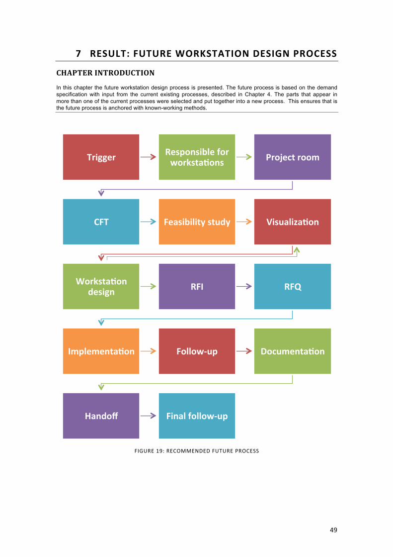
49
7 RESULT: FUTURE WORKSTATION DESIGN PROCESS
CHAPTER INTRODUCTION
In this chapter the future workstation design process is presented. The future process is based on the demand specification with input from the current existing processes, described in Chapter 4. The parts that appear in more than one of the current processes were selected and put together into a new process. This ensures that is the future process is anchored with known-working methods.
FIGURE 19: RECOMMENDED FUTURE PROCESS
Trigger Responsible for workstaeons Project room
CFT Feasibility study Visualizaeon
Workstaeon design RFI RFQ
Implementaeon Follow-‐up Documentaeon
Handoff Final follow-‐up

50
TRIGGER
A new product/variant puts new demands on the current workstations, they might need a redesign or new workstations need to be built to meet these new demands. The Lean Workstation Design Process could also be triggered by an in-‐house Kaizen, where perhaps an ergonomic issue or similar has been raise.
RESPONSIBLE FOR WORKSTATIONS
The responsible actor for workstations summons an initial CFT, in Table 10 a proposal is given for suitable actors. It is important at this stage that there is an actor or role within the company that is in charge of workstations or at least initially in charge. It is his or her job to set up the CFT or summon the different competences. The composition of the cross functional team will change over time and will be of varying size, depending on the extent of the workstation design project.
PROJECT ROOM
It is important to provide the right prerequisites for the CFT to get as good results as possible. A common tool to increase the communication between the cross functional team members is the use of a big room, Obeya (Morgan & Liker, 2006). The meetings in Obeyas serve two main purposes, namely: information gathering and information management (Morgan & Liker, 2006). The walls of the room can then be decorated with important information such as, charts, spaghetti diagrams, performance indicators, schedules, time plans, and other information that can help the CFT to make well-‐informed decisions. In this stage it is also important to gather other resources that might be needed throughout the project, perhaps computers will be needed and some software.
CFT
The CFT proposal in Table 10 is developed from the data gathered during the factory visits, but with one addition: the 3D-‐visualization. The company is not in the front edge when it comes to 3D-‐visalization but the researchers still think it is important to make room for the different tools available within virtual manufacturing in the future process, since visualization is an important means to enable all participants in the CFT to fully understand the design and the different proposals to be able to contribute to the full extent.
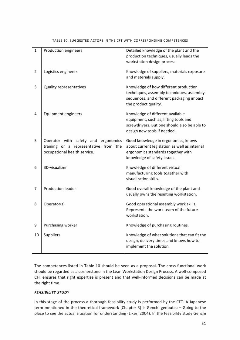
51
TABLE 10. SUGGESTED ACTORS IN THE CFT WITH CORRESPONDING COMPETENCES
1 Production engineers Detailed knowledge of the plant and the production techniques, usually leads the workstation design process.
2 Logistics engineers Knowledge of suppliers, materials exposure and materials supply.
3 Quality representatives Knowledge of how different production techniques, assembly techniques, assembly sequences, and different packaging impact the product quality.
4 Equipment engineers Knowledge of different available equipment, such as, lifting tools and screwdrivers. But one should also be able to design new tools if needed.
5 Operator with safety and ergonomics training or a representative from the occupational health service.
Good knowledge in ergonomics, knows about current legislation as well as internal ergonomics standards together with knowledge of safety issues.
6 3D-‐visualizer Knowledge of different virtual manufacturing tools together with visualization skills.
7 Production leader Good overall knowledge of the plant and usually owns the resulting workstation.
8 Operator(s) Good operational assembly work skills. Represents the work team of the future workstation.
9 Purchasing worker Knowledge of purchasing routines.
10 Suppliers Knowledge of what solutions that can fit the design, delivery times and knows how to implement the solution
The competences listed in Table 10 should be seen as a proposal. The cross functional work should be regarded as a cornerstone in the Lean Workstation Design Process. A well-‐composed CFT ensures that right expertise is present and that well-‐informed decisions can be made at the right time.
FEASIBILITY STUDY
In this stage of the process a thorough feasibility study is performed by the CFT. A Japanese term mentioned in the theoretical framework (Chapter 3) is Genchi genbutsu – Going to the place to see the actual situation for understanding (Liker, 2004). In the feasibility study Genchi
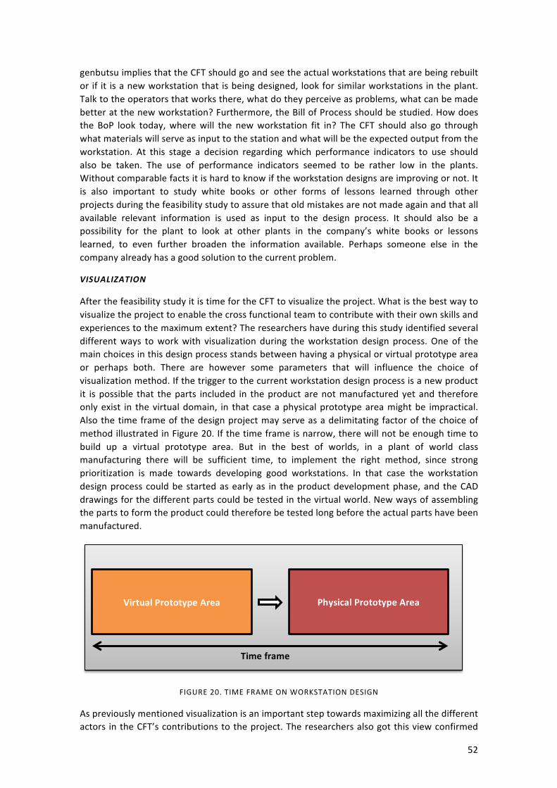
52
genbutsu implies that the CFT should go and see the actual workstations that are being rebuilt or if it is a new workstation that is being designed, look for similar workstations in the plant. Talk to the operators that works there, what do they perceive as problems, what can be made better at the new workstation? Furthermore, the Bill of Process should be studied. How does the BoP look today, where will the new workstation fit in? The CFT should also go through what materials will serve as input to the station and what will be the expected output from the workstation. At this stage a decision regarding which performance indicators to use should also be taken. The use of performance indicators seemed to be rather low in the plants. Without comparable facts it is hard to know if the workstation designs are improving or not. It is also important to study white books or other forms of lessons learned through other projects during the feasibility study to assure that old mistakes are not made again and that all available relevant information is used as input to the design process. It should also be a possibility for the plant to look at other plants in the company’s white books or lessons learned, to even further broaden the information available. Perhaps someone else in the company already has a good solution to the current problem.
VISUALIZATION
After the feasibility study it is time for the CFT to visualize the project. What is the best way to visualize the project to enable the cross functional team to contribute with their own skills and experiences to the maximum extent? The researchers have during this study identified several different ways to work with visualization during the workstation design process. One of the main choices in this design process stands between having a physical or virtual prototype area or perhaps both. There are however some parameters that will influence the choice of visualization method. If the trigger to the current workstation design process is a new product it is possible that the parts included in the product are not manufactured yet and therefore only exist in the virtual domain, in that case a physical prototype area might be impractical. Also the time frame of the design project may serve as a delimitating factor of the choice of method illustrated in Figure 20. If the time frame is narrow, there will not be enough time to build up a virtual prototype area. But in the best of worlds, in a plant of world class manufacturing there will be sufficient time, to implement the right method, since strong prioritization is made towards developing good workstations. In that case the workstation design process could be started as early as in the product development phase, and the CAD drawings for the different parts could be tested in the virtual world. New ways of assembling the parts to form the product could therefore be tested long before the actual parts have been manufactured.
FIGURE 20. TIME FRAME ON WORKSTATION DESIGN
As previously mentioned visualization is an important step towards maximizing all the different actors in the CFT’s contributions to the project. The researchers also got this view confirmed
Physical Prototype Area
Virtual Prototype Area
Time frame
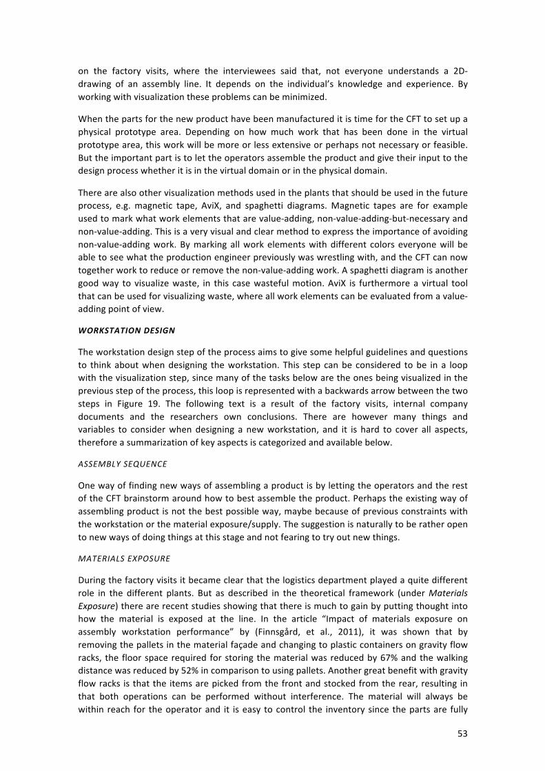
53
on the factory visits, where the interviewees said that, not everyone understands a 2D-‐drawing of an assembly line. It depends on the individual’s knowledge and experience. By working with visualization these problems can be minimized.
When the parts for the new product have been manufactured it is time for the CFT to set up a physical prototype area. Depending on how much work that has been done in the virtual prototype area, this work will be more or less extensive or perhaps not necessary or feasible. But the important part is to let the operators assemble the product and give their input to the design process whether it is in the virtual domain or in the physical domain.
There are also other visualization methods used in the plants that should be used in the future process, e.g. magnetic tape, AviX, and spaghetti diagrams. Magnetic tapes are for example used to mark what work elements that are value-‐adding, non-‐value-‐adding-‐but-‐necessary and non-‐value-‐adding. This is a very visual and clear method to express the importance of avoiding non-‐value-‐adding work. By marking all work elements with different colors everyone will be able to see what the production engineer previously was wrestling with, and the CFT can now together work to reduce or remove the non-‐value-‐adding work. A spaghetti diagram is another good way to visualize waste, in this case wasteful motion. AviX is furthermore a virtual tool that can be used for visualizing waste, where all work elements can be evaluated from a value-‐adding point of view.
WORKSTATION DESIGN
The workstation design step of the process aims to give some helpful guidelines and questions to think about when designing the workstation. This step can be considered to be in a loop with the visualization step, since many of the tasks below are the ones being visualized in the previous step of the process, this loop is represented with a backwards arrow between the two steps in Figure 19. The following text is a result of the factory visits, internal company documents and the researchers own conclusions. There are however many things and variables to consider when designing a new workstation, and it is hard to cover all aspects, therefore a summarization of key aspects is categorized and available below.
ASSEMBLY SEQUENCE
One way of finding new ways of assembling a product is by letting the operators and the rest of the CFT brainstorm around how to best assemble the product. Perhaps the existing way of assembling product is not the best possible way, maybe because of previous constraints with the workstation or the material exposure/supply. The suggestion is naturally to be rather open to new ways of doing things at this stage and not fearing to try out new things.
MATERIALS EXPOSURE
During the factory visits it became clear that the logistics department played a quite different role in the different plants. But as described in the theoretical framework (under Materials Exposure) there are recent studies showing that there is much to gain by putting thought into how the material is exposed at the line. In the article “Impact of materials exposure on assembly workstation performance” by (Finnsgård, et al., 2011), it was shown that by removing the pallets in the material façade and changing to plastic containers on gravity flow racks, the floor space required for storing the material was reduced by 67% and the walking distance was reduced by 52% in comparison to using pallets. Another great benefit with gravity flow racks is that the items are picked from the front and stocked from the rear, resulting in that both operations can be performed without interference. The material will always be within reach for the operator and it is easy to control the inventory since the parts are fully
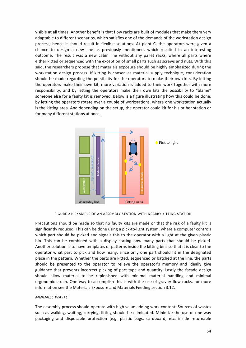
54
visible at all times. Another benefit is that flow racks are built of modules that make them very adaptable to different scenarios, which satisfies one of the demands of the workstation design process; hence it should result in flexible solutions. At plant C, the operators were given a chance to design a new line as previously mentioned, which resulted in an interesting outcome. The result was a new cabin line without any pallet racks, where all parts where either kitted or sequenced with the exception of small parts such as screws and nuts. With this said, the researchers propose that materials exposure should be highly emphasized during the workstation design process. If kitting is chosen as material supply technique, consideration should be made regarding the possibility for the operators to make their own kits. By letting the operators make their own kit, more variation is added to their work together with more responsibility, and by letting the operators make their own kits the possibility to “blame” someone else for a faulty kit is removed. Below is a figure illustrating how this could be done, by letting the operators rotate over a couple of workstations, where one workstation actually is the kitting area. And depending on the setup, the operator could kit for his or her station or for many different stations at once.
FIGURE 21: EXAMPLE OF AN ASSEMBLY STATION WITH NEARBY KITTING STATION
Precautions should be made so that no faulty kits are made or that the risk of a faulty kit is significantly reduced. This can be done using a pick-‐to-‐light system, where a computer controls which part should be picked and signals this to the operator with a light at the given plastic bin. This can be combined with a display stating how many parts that should be picked. Another solution is to have templates or patterns inside the kitting bins so that it is clear to the operator what part to pick and how many, since only one part should fit in the designated place in the pattern. Whether the parts are kitted, sequenced or batched at the line, the parts should be presented to the operator to relieve the operator's memory and ideally give guidance that prevents incorrect picking of part type and quantity. Lastly the facade design should allow material to be replenished with minimal material handling and minimal ergonomic strain. One way to accomplish this is with the use of gravity flow racks, for more information see the Materials Exposure and Materials Feeding section 3.12.
MINIMIZE WASTE
The assembly process should operate with high value adding work content. Sources of wastes such as walking, waiting, carrying, lifting should be eliminated. Minimize the use of one-‐way packaging and disposable protection (e.g. plastic bags, cardboard, etc. inside returnable
Assembly line Kitting area
Material facade
Material facade
Workstation Operator movem
ent
Pick to light

55
packaging), though caution should be made with regards to quality aspects. Tools and equipment should be positioned within reach at the workplace to minimize operator walking. Material racks should be positioned within 1-‐2 steps to minimize operator walking.
5S
Build the workstation to enable 5S, see Chapter 3.5. Build the workstation so that it is possible to keep clean. The material façade and all other tables and machines should be placed on wheels if possible; the wheels are implemented to ease cleaning and to increase flexibility. Sometimes it is not wise, since some machines require stability to operate. Avoid flat surfaces that are not used for assembly operations, since they are likely to become buffers or places to put trash. All material, tools or operator utilities should have a designated space. For instance, if the operators want to have water bottles at the station there should be a designated place to put them. When designing or buying tools and machines, consideration should be made towards the use of the machine and where it is supposed to be used, so that buttons are in reach for the operator and that warning lamps are clearly visible.
STANDARDIZED WORK
There should be no alternative options of what to do, which means that the operator should only be able to perform a task in one way, the best way. This can be built in the design by for example presenting the material in the order it should be used, or by using mistake proofing, a so called Poka-‐yoke method. Perhaps by using a computer system that supervises the assembly and if not all work elements are performed the operator cannot move on to the next task; e.g. only five screws have been mounted, it should be six, and an alarm sounds. Nor should one have to choose between different options to complete the task, there should only be one way. The normal condition is clearly defined, and it is easy to see when there is an abnormal condition and this can be quickly highlighted in order for corrective action to be taken. This can be accomplished by visual aids, e.g. a simple picture showing the normal condition of the workstation.
FLEXIBILITY
All equipment should be easy to quickly move and rearrange to support flexibility. If the equipment are easy to move and rearrange the workstations support quick rebalancing, which is needed when there is a change in production volume. The ability to move equipment around easily also facilitates the introduction of new product variants, since the production sequence is not locked. Flexible stations also ease the improvement work, since the work teams at the stations can perform more extensive improvement work on their own. And by using flexible material façade designs such as gravity flow racks, their size can easily be adjusted by removing or adding modules, which also increases the ability of the work teams to perform improvement work. One way to further increase the flexibility of the production system is to design the workstations so that operators can be responsible for a larger work area, perhaps spanning over several workstations; it will then be easier to scale the production up and down.
ERGONOMICS/SAFETY
Pre-‐CASA is made to assess ergonomics in the design phase together with a PFMEA to identify safety risks. Tools and equipment should not cause ergonomic strain on the operator. Make sure that the operator does not have to climb on, in or under the work item to access it to perform the work. The workstation should provide possibilities for height adjustment, when it is possible; if it is not possible, make sure to address other possibilities for height adjustment, e.g. height adjustable floor. Handling of heavy parts within the work area should be minimized

56
to avoid risk of injury, ergonomic strain, and when needed, lifting equipment should be provided.
ENVIRONMENT
Different forms of environmental waste should be sorted at the source, i.e. if an activity generates environmental waste, appropriate bins should be provided nearby, to make sure that a minimum of waste is not recycled. By reduction of one-‐way packaging in the plant, waste amounts should decrease. Waste categories should be defined to achieve sorting of all forms of waste (not just hazardous/non-‐hazardous).
WORKPLACE ORGANIZATION AND THE PEOPLE
In previous parts of this chapter a lot of methods and tips have been provided to help design good workstations. There are however “soft topics” that do not fit under previous topics but nevertheless deserve attention during the workstation design process. Communication is one of these topics; it is important that the employees and the operators communicate during the work day. By increasing communication the “us” and “them” feeling should decrease, which could increase the feeling of belonging and uniting the plant towards the goal of becoming a world class manufacturing plant. By implementing previous proposals, operators will not only be involved in the improvement work to a higher extent, but also be able to take part in the workstation design processes. And by decreasing the use of material racks in favor of gravity flow racks the visibility in the plant will increase, thus the transparency will increase as well. There are also other ways of increasing communication, for example by introducing whiteboards at the lines where the work team can keep track of improvements or other activities, such as skill levels, targets, and much more.
RFI
A Request for Information is to be sent out to interesting suppliers, which aims at obtaining written information about their capabilities. The RFI includes some information of the project and what is expected to be delivered from the suppliers. The goal is to check whether the suppliers actually can produce and deliver the new design proposal, or parts of it. This will result in a list with all the suppliers that are willing and able to fulfill the request. The figure below illustrates how the RFI procedure might work.
Firstly an RFI is sent out to known suppliers in the field, then their answers are collected and the suppliers that have the appropriate capabilities and have interest in working together with the plant are taken to the next step.
RFI
Supplier A
Supplier B
Supplier C
Supplier D
Supplier A
Supplier C
Possible suppliers
Interested suppliers
FIGURE 22. RFI ILLUSTRATION
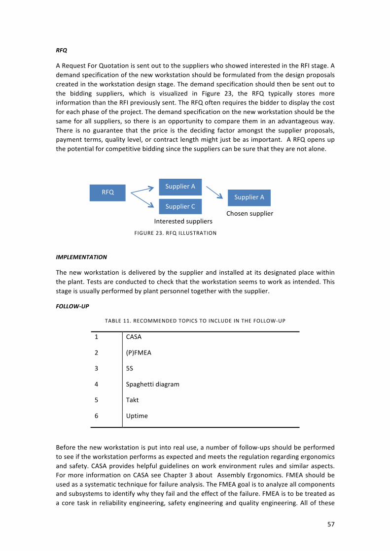
57
RFQ
A Request For Quotation is sent out to the suppliers who showed interested in the RFI stage. A demand specification of the new workstation should be formulated from the design proposals created in the workstation design stage. The demand specification should then be sent out to the bidding suppliers, which is visualized in Figure 23, the RFQ typically stores more information than the RFI previously sent. The RFQ often requires the bidder to display the cost for each phase of the project. The demand specification on the new workstation should be the same for all suppliers, so there is an opportunity to compare them in an advantageous way. There is no guarantee that the price is the deciding factor amongst the supplier proposals, payment terms, quality level, or contract length might just be as important. A RFQ opens up the potential for competitive bidding since the suppliers can be sure that they are not alone.
IMPLEMENTATION
The new workstation is delivered by the supplier and installed at its designated place within the plant. Tests are conducted to check that the workstation seems to work as intended. This stage is usually performed by plant personnel together with the supplier.
FOLLOW-‐UP
TABLE 11. RECOMMENDED TOPICS TO INCLUDE IN THE FOLLOW-‐UP
1 CASA
2 (P)FMEA
3 5S
4 Spaghetti diagram
5 Takt
6 Uptime
Before the new workstation is put into real use, a number of follow-‐ups should be performed to see if the workstation performs as expected and meets the regulation regarding ergonomics and safety. CASA provides helpful guidelines on work environment rules and similar aspects. For more information on CASA see Chapter 3 about Assembly Ergonomics. FMEA should be used as a systematic technique for failure analysis. The FMEA goal is to analyze all components and subsystems to identify why they fail and the effect of the failure. FMEA is to be treated as a core task in reliability engineering, safety engineering and quality engineering. All of these
RFQ Supplier A
Supplier C Supplier A
Interested suppliers Chosen supplier
FIGURE 23. RFQ ILLUSTRATION
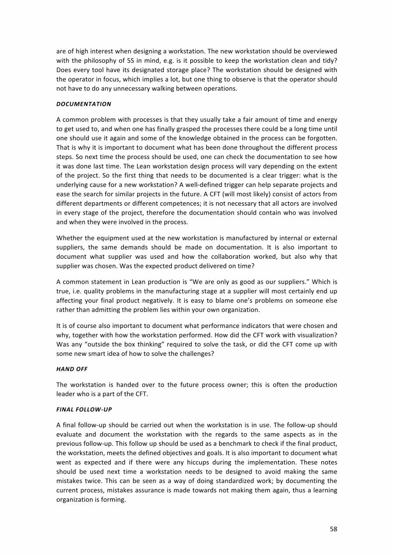
58
are of high interest when designing a workstation. The new workstation should be overviewed with the philosophy of 5S in mind, e.g. is it possible to keep the workstation clean and tidy? Does every tool have its designated storage place? The workstation should be designed with the operator in focus, which implies a lot, but one thing to observe is that the operator should not have to do any unnecessary walking between operations.
DOCUMENTATION
A common problem with processes is that they usually take a fair amount of time and energy to get used to, and when one has finally grasped the processes there could be a long time until one should use it again and some of the knowledge obtained in the process can be forgotten. That is why it is important to document what has been done throughout the different process steps. So next time the process should be used, one can check the documentation to see how it was done last time. The Lean workstation design process will vary depending on the extent of the project. So the first thing that needs to be documented is a clear trigger: what is the underlying cause for a new workstation? A well-‐defined trigger can help separate projects and ease the search for similar projects in the future. A CFT (will most likely) consist of actors from different departments or different competences; it is not necessary that all actors are involved in every stage of the project, therefore the documentation should contain who was involved and when they were involved in the process.
Whether the equipment used at the new workstation is manufactured by internal or external suppliers, the same demands should be made on documentation. It is also important to document what supplier was used and how the collaboration worked, but also why that supplier was chosen. Was the expected product delivered on time?
A common statement in Lean production is “We are only as good as our suppliers.” Which is true, i.e. quality problems in the manufacturing stage at a supplier will most certainly end up affecting your final product negatively. It is easy to blame one’s problems on someone else rather than admitting the problem lies within your own organization.
It is of course also important to document what performance indicators that were chosen and why, together with how the workstation performed. How did the CFT work with visualization? Was any “outside the box thinking” required to solve the task, or did the CFT come up with some new smart idea of how to solve the challenges?
HAND OFF
The workstation is handed over to the future process owner; this is often the production leader who is a part of the CFT.
FINAL FOLLOW-‐UP
A final follow-‐up should be carried out when the workstation is in use. The follow-‐up should evaluate and document the workstation with the regards to the same aspects as in the previous follow-‐up. This follow up should be used as a benchmark to check if the final product, the workstation, meets the defined objectives and goals. It is also important to document what went as expected and if there were any hiccups during the implementation. These notes should be used next time a workstation needs to be designed to avoid making the same mistakes twice. This can be seen as a way of doing standardized work; by documenting the current process, mistakes assurance is made towards not making them again, thus a learning organization is forming.
59
8 REFERENCES
Almgren, J. & Schaurig, C., 2012. The influence of production ergonomics on product quality, Göteborg: s.n.
Annet, K., Duncan, R. & Stammers, M. G., 1971. Task Analysis. Department of Employment Training Information Paper 6, London: HMSO.
Arbetsförmedlingen, 2004. Arbetskraftsutbudet i Sverige -‐ en utblick mot 2030. 2004(3).
Baudin, M., 2002. Lean Assembly: The Nuts and Bolts of Making Assembly Operations Flow. New York: Productivity Press.
Bohgard, M. et al., 2009. Work and technology on human terms. Göteborg, Linköping, Luleå, Lund, Stockholm, Östersund: Prevent.
Company, 2004. Corporate Standard 8003,2, s.l.: Internal document.
Company, 2008. A company's production system academy. [Online] [Accessed 18 April 2013].
Company, 2010. Management System Training, s.l.: Internal document.
Company, 2010. Process Knowledge E-‐learning, s.l.: Internal document.
Emeraldinsight, 2013. [Art].
Eriksson, B., 2007. Flexibilitet -‐ ett exempel från forskning om flexibla organisationer och dess konsekvenser för arbetsmiljön. Arbetsmarknad & arbetsliv.
European Social Survey, 2012. European Social Survey. [Online] Available at: http://www.europeansocialsurvey.org/ [Accessed 5 March 2013].
Fastems, 2013. [Art].
Finnsgård, C., Wänström, C., Medbo, L. & Neumann, P., 2011. Impact of materials exposure on. International Journal of Production.
Företagshälsovården, 2009. VOLVO ANALYSSYSTEM ARBETSMILJÖ. [Online] [Accessed 1 March 2013].
Gabrielsson, J., 2010. Lean produktutveckling: ett arbete om kunskapbaserad produktutveckling med fokus på tvärfunktionellt samarbete & lärande, Stockholm: KTH.
Ghosh, S. & Gagnon, R. J., 1989. A comprehensive literature review and analysis of the design, balancing and scheduling of assembly systems. International Journal of Production Research, 27(4), pp. 637-‐670.
Griffin, A., 1997. PDMA Research on New Product Devlopment Practices: Updating Trends and Benchmarking Best Practices, New York: Elsevier Science Inc..
Grönlund, A., 2007. Egenkontroll som firskfaktor och riskfaktor. Det gränslösa arbetet i Västeurpoa och Sverige. Arbetsmarknad & Arbetsliv, pp. 11-‐25.
60
Hanson, R., 2012. In-‐plant materials supply: Supporting the choice between kitting and continous supply. Gothenburg: Chalmers Reproservice.
Hanson, R., 2012. In-‐plant materials supply: Supporting the choice between kitting and continous supply, Gothenburg: Chalmers Reproservice.
Hignett, S. & McAtamney, L., 2000. Rapid Entire Body Assessment (REBA). Applied Ergonomics, 31(2), pp. 201-‐205.
Holland, S., Gaston, K. & Gomes, J., 2000. Critical success factors for cross-‐functional teamwork in new product development, Oxford: Black Well Publishers Ltd..
Håkansson, K. & Isidorsson, T., 2006. Arbetsmiljöarbete och långsiktigt hållbara arbetsorganisationer. Arbete och hälsa, Volume 16.
International Ergonomics Association, 2000. Definition of Ergonomics. [Online] Available at: http://www.iea.cc/01_what/What%20is%20Ergonomics.html [Accessed 19 March 2013].
Lantz, A., 1993. Interjuvmetodik. Lund: Studentlitteratur.
Lean Enterprise Institute , 2009. STANDARDIZED WORK: THE FOUNDATION FOR KAIZEN. [Online] Available at: http://www.lean.org/workshops/WorkshopDescription.cfm?WorkshopId=20 [Accessed 13 April 2013].
Liker, J. K., 2004. The Toyota Way: 14 Management Principles from the World's Greatest Manufacturer. s.l.:McGraw-‐Hill.
Liker, J. K. & Meier, D., 2006. The Toyota Way Fieldbook: A Practical Guide for Implementing Toyota's 4Ps. s.l.:McGraw-‐Hill.
Marksberry, P., Rammohan, R. & Vu, D., 2011. A systems study on standardised work: a Toyota perspective. Int. J. Productivity and Quality Management, 7(3), pp. 287-‐303.
McAtamney, L. & Corlett, E. N., 1993. RULA: a survey method for the investigation of work-‐related upper limb disorders. Applied Ergonomics, 24(2), pp. 91-‐99.
MindTools, 2013. Setting up a Cross-‐Functional Team. [Online] Available at: http://www.mindtools.com/pages/article/cross-‐functional-‐team.htm [Accessed 08 04 2013].
Morgan, J. M. & Liker, J. K., 2006. The Toyota Product Development System: Integrating People, Process, and Technology. New York: Productivity Press.
Ontario Ministry of Labour, 2009. Prevent Workplace Pains & Strains! It's time to take action!. [Online] Available at: http://www.labour.gov.on.ca/english/hs/pubs/ergonomics/is_ergonomics.php [Accessed 13 March 2013].
Panero, J. & Zelnick, M., 1979. Human Dimension and Interior Space: A Source Book of Design Reference Standards. s.l.:Watson-‐Guptill.
Patel, R. & Davidson, B., 2011. Forkningsmetodikens grunder. 4th ed. s.l.:Studentlitteratur AB.

61
Roos, D., Womack, J. P. & Jones, D. T., 1991. The Machine That Changed the World : The Story of Lean Production. s.l.:Harper Perennial.
Sigvard, R., 1994. Organisationspsykologi och ledarskap. Göteborg: Akademiförlaget.
Stanton, N. A., 2006. Hierarchical task analysis: Developments, applications, and extensions. Applied Ergonomics, 37(1), pp. 55-‐79.
Statistiska centralbyrån, 2013. Statistiska centralbyrån. [Online] Available at: http://www.scb.se/Pages/Article____352498.aspx [Accessed 13 May 2013].
Szücs, S., 2004. Omorganisation och ohälsa. Skyddsombuden vid kommunala arbetsplatser. Arbete och Hälsa, Volume 14.
Taylor, D., 2013. The Literature Review: A Few Tips On Conducting It. [Online] Available at: http://www.writing.utoronto.ca/advice/specific-‐types-‐of-‐writing/literature-‐review [Accessed 5 02 2013].
Tompkins, J. A., White, J. A. & Bozer, Y. A., 2010. Facilities Planning. s.l.:JOHN WILEY & SONS.
Truman, D., 2002. Forklift-‐Free Factory Floors Gain Popularity. Knight Ridder Tribune Business News, 1(1), p. 1.
UK Health and Safety Executive, 2013. Musculoskeletal disorders. [Online] Available at: http://www.hse.gov.uk/msd/index.htm [Accessed 13 March 2013].
Weber, A., 2005. Lean Workstations: Organized for Productivity. Assembly Lean Manufacturing.
Wild, R., 1975. On the selection of mass production systems. International Journal of Production Research, 13(5), pp. 443-‐462.
Willaert, P., Van den Bergh, J., Willems, J. & Deschoolmeester, D., 2007. The Process-‐Oriented Organisation: A Holistic View Developing a Framework for Business Process Orientation Maturity. In: Business Process Management. Berlin: Springer Berlin Heidelberg, pp. 1-‐15.
Wojcikiewics, K., 2003. Manufacturing Engineering, Buchana: s.n.
Woolson, D. & Husar, M. A., 2004. Transforming a Plant to Lean in a Large, Traditional Company: Delphi Saginaw Steering Systems, GM. In: Becoming Lean: Inside stories of U.S. manufactures. New York: Productivity Press, p. 136.
Woolson, D. & Husar, M. A., 2004. Transforming a Plant to Lean in a Large, Traditional Company: Delphi Saginaw Steering Systems, GM. In: J. K. Liker, ed. Becoming Lean: Inside Stories of U.S. Manufacturers. New York: Productivity Press, pp. 121-‐161.
Wänström, C. & Medbo, L., 2009. The impact of materials feeding design on assembly, s.l.: Journal of Manufacturing Technology Management.
Xu, Z., Ko, J., Cochran, D. J. & Jung, M.-‐C., 2012. Design of assembly lines with the concurrent consideration of productivity. Comupters & Industrial Engineering, 1 March, 62(2), pp. 431-‐441.

62
Yamashina, H., 2010. Workplace Organization, Kyoto: s.n.
Yount, R., 2006. Observation. [Online] Available at: http://www.napce.org/documents/research-‐design-‐yount/09_Obs_4th.pdf [Accessed 7 February 2013].
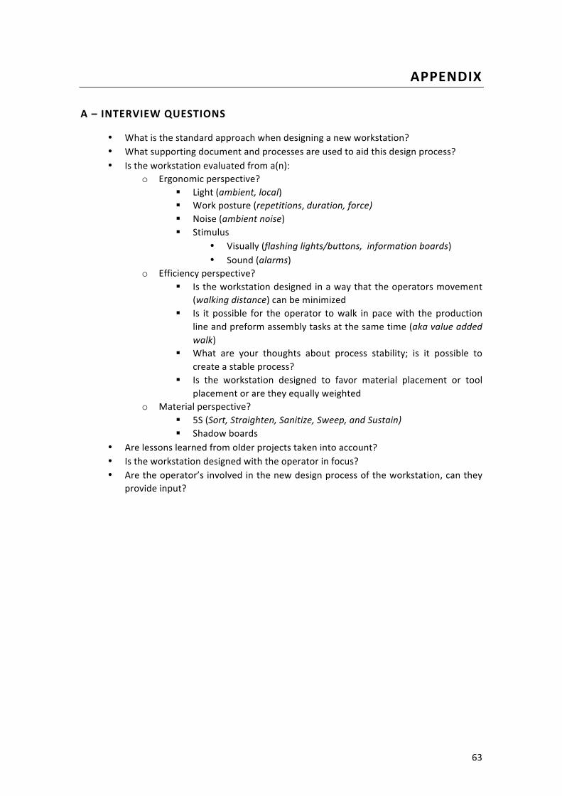
63
APPENDIX
A – INTERVIEW QUESTIONS
• What is the standard approach when designing a new workstation? • What supporting document and processes are used to aid this design process? • Is the workstation evaluated from a(n):
o Ergonomic perspective? § Light (ambient, local) § Work posture (repetitions, duration, force) § Noise (ambient noise) § Stimulus
• Visually (flashing lights/buttons, information boards) • Sound (alarms)
o Efficiency perspective? § Is the workstation designed in a way that the operators movement
(walking distance) can be minimized § Is it possible for the operator to walk in pace with the production
line and preform assembly tasks at the same time (aka value added walk)
§ What are your thoughts about process stability; is it possible to create a stable process?
§ Is the workstation designed to favor material placement or tool placement or are they equally weighted
o Material perspective? § 5S (Sort, Straighten, Sanitize, Sweep, and Sustain) § Shadow boards
• Are lessons learned from older projects taken into account? • Is the workstation designed with the operator in focus? • Are the operator’s involved in the new design process of the workstation, can they
provide input?
64
B – INTERVIEW FOLLOW UP QUESTIONS ON PLACE C
• How much time is put into the different phases during the development of a new workstation? (layout, ergonomics and logistics etc.)
• If the operator is set in will that reflect in the result of the new workstation? • In what grade are the operator’s wishes prioritized in the design process? • Who sets the budget and when is it either approved or denied? • Do the involved departments have a shared vision? What KPIs are of interest? • What obstacles could hinder the possibility to put the operator in focus?

65
C – DEMANDS SPECIFICATION OF THE WORKSTATION DESIGN PROCESS
TABLE 12: DEMAND SPECIFICATION OF A WORKSTATION
1 The workstation must be well structured, clean, and provide good visibility over the plant
2 The workstation must be adapted to the operators needs in the utmost to ensure good ergonomics
3 A stable production flow
4 No unnecessary movement for the operator
5 The workstation must ease the operator to perform ones job
6 An operator should not have to make an active choose between two or more options
7 The workstation must be easy to relocate and make adjustments on
TABLE 13: DEMANDS SPECIFICATION OF THE DEMAND SPECIFICATION OF THE WORKSTATION DESIGN PROCESS
1 Accomplish the same result every time
2 The process must be documented, trigger should be documented to ease the search of similar projects
3 Lead time, effectiveness
4 Good quality
5 Intuitive, self-‐learning

66
TABLE 14: DEMANDS SPECIFICATION OF THE WORKSTATION DESIGN PROCESS
1 Must guarantee that the resulting workstation can be kept clean, is well-‐structured and provide good visibility over of the plant
2 Must include the operator so that one’s knowledge is incorporated in the solution, operators must be able to affect the outcome
3 The process must ensure a stable product flow
4 The process must result in a design without unnecessary movements for the operator
5 The process must guarantee good ergonomics
6 The process should ease the CFT in visualizing both problems and solution amongst them self and external parties.
7 The process should guide the CFT to purchase the rights equipment with respect to the environment i.e. the off button must be reachable.