lecture notes - government polytechnic, nayagarh
TRANSCRIPT

MANUFACTURING TECHNOLOGY
Page 1
LECTURE NOTES
������������
��� ������
�������
�
(4th
semester MECHANICAL ENGINEERING)
Prepared By
Soma Dalbehera
Lecturer Mechanical Engineering
GP Nayagarh

MANUFACTURING TECHNOLOGY
Page 2
�����������������������������
Total Periods 60
�
��������
�
1.0 Tool Materials
1.1 Composition of various tool materials
1.2 Physical properties& uses of such tool materials.
2.0 Cutting Tool 2.1 Cutting action of various hand tools such as Chisel, hack saw blade, dies and reamer
2.2 Turning tool geometry and purpose of tool angle
2.3 Machining process parameters
2.4 Coolant and lubricant in machining purposes
3.0 Lathe Machines
3.1 Construction and working of lathe
• Major components of a lathe and their function
• Operations carried out in a lathe (Turning, thread cutting, taper turning, internal
machining, parting off, facing, knurling)
• Safety measures during machining
3.2 Capstan Lathe
• Difference with respect to engine lathe
• Major components and their function
• Define multiple tool holders
Name of the Course: Diploma in Mech/Auto/ & Other Mechanical Allied Branches
Course code: TH-2 Semester 4th
Total Period: 60 Examination 3 hrs
Theory periods: 4 P/W Class Test: 20
Maximum marks: 100 End Semester
Examination:
80
Sl. No. Topic Periods 01 Tool Materials 04
02 Cutting Tools 06
03 Lathe Machine 08
04 Shaper 06
05 Planning Machine 06
06 Milling Machine 08
07 Slotter 06
08 Grinding 06
09 Internal Machining operations 06
10 Surface finish, lapping 04

MANUFACTURING TECHNOLOGY
Page 3
3.3 Turret Lathe
• Difference with respect to capstan lathe
• Major components and their function
3.4 Draw the tooling lay out for preparation of a hexagonal bolt & bush
4.0 Shaper Machine
4.1 Potential application areas of a shaper machine
4.2 Major components and their function
4.3 Explain the automatic able feed mechanism
4.4 Explain the construction &working of tool head
4.5 Explain the quick return mechanism through sketch
4.6 State the specification of a shaping machine.
5.0 Planning Machine
5.1 Application area of a planer and its difference with respect to shaper
5.2 Major components and their functions
5.3 The table drive mechanism
5.4 Working of tool and tool support
5.5 Clamping of work through sketch.
6.0 Milling Machine
6.1Types of milling machine and operations performed by them
6.2 Construction & working of simple dividing head, universal dividing
head
6.3 Procedure of simple and compound indexing
6.4 Illustration of different indexing methods
7.0 Slotter
7.1 Major components and their function
7.2 Construction and working of slotter machine
7.3 Tools used in slotter
8.0 Grinding
8.1 Significance of grinding operations
8.2 Manufacturing of grinding wheels
8.3 Criteria for selecting of grinding wheels
8.4 Specification of grinding wheels with example
Working of
• Cylindrical Grinder
• Surface Grinder
• Centreless Grinder
9.0 Internal Machining operations
Classification of drilling machines
9.1 Working of
• Bench drilling machine
• Pillar drilling machine
• Radial drilling machine
9.2 Boring
• Basic Principle of Boring

MANUFACTURING TECHNOLOGY
Page 4
• Different between Boring and drilling
9.3 Broaching
• Types of Broaching(pull type, push type)
• Advantages of Broaching and applications
10.0 Surface finish, lapping
10.1 Definition of Surface finish
10.2 Description of lapping& explain their specific cutting.
MANUFACTURING TECHNOLOGY
Page 5
Tool Materials
Chapter-1
Manufacturing technology:
It is defined as a field of study focused on process techniques or
equipments, cost reduction, increased efficiency, enhanced reliability,
security safety and anti-pollution measures are its objects.
Tool Material:
The characteristic of the ideal cutting tool material are-
(a) Hot hardness
(b) Wear resistance
(c) Toughness
(d) Cost and easiness in fabrication

MANUFACTURING TECHNOLOGY
Page 6
Hot hardness:
The material must remain hander than the the work material at
elevated operating temperatures.
Wear resistances:
The material must withstand excessive were even through the
relative hardness of the tool-work materials changes.
Toughness:
The term toughness actually implies a combination of strength and
ductility. The material must have sufficient toughness to withstand shocks
and vibrations and to prevent breakage.
Cost and easiness in fabrication:
The cost and easiness of fabrication should have within reasonable
limits.
State the composition of various tool material
The cutting tool materials are-:
1. Carbon steels
2. Medium alloy steel
3. High speed steels
4. Stellites
5. Cemented carbides
6. Ceramics
7. Diamonds
8. Abrasives
9. Cubic boron nitride(CBN)

MANUFACTURING TECHNOLOGY
Page 7
Composition of carbon steels:
Carbon steels contain carbon in amounts ranging fron 0.008 to 1.5%
Composition of medium alloy steel:
The high carbon medium alloy steels have a carbon content akin to
plain carbon steels,but in addition there is ,say up to 5% alloy content
consisting there of tungsten,molybdenum,chromium and vanadium.
Composition of high speed steel:
High speed steel is the general pupose metal for low and medium
cutting speed owing to its soperior three type of high speed steel
1. High tungsten
2. High molybdenum
3. High cobalt
Actually these three named modify as following
1. 18-4-1 high speed steel (T-series)
2. Molybdenum high speed steel(M-series)
3. Cobalt high speed steel
Composition of 18-4-1 high speed steel (T-series)-
This steel containing 18% tungsten, 4% Cr & 1% vanadium, is
considered to be one of the best of all purpose o f tool steel.
Composition of molybdenum high speed steel (M-series):
This steel containing 6% Molybdenum,6%W,4% Cr % & 2%
vanadium.
Composition of cobalt high speed steel:
This is sometimes called super high speed steel. Cobalt is added from
2 to 15% to increase of the steel containt 20% tungsten 4%cr, 2% v & 12%
cobalt.

MANUFACTURING TECHNOLOGY
Page 8
Composition of satellites:
Satellites are the trade name of a nonferrous cost alloy cobalt,
chromium and tungsten. The ranges of elements in these alloys is40 to 48%,
30 to 35% Cr & 12 to 19% tungsten.
Composition of cemented carbides:
A typical analysis of a carbide suitable for steel machining is 82%
tungsten carbide,10% titanium carbide and 8% cobalt.
Composition of ceramics:
The latest development in the metal cutting tools use Al oxide
generally referred to as ceramics
Tools are made by composing aluminium oxide powder in a mould
at about 280 kg/cm2 or more.
Composition of diamonds:
The diamonds are used for cutting tools are industrial diamonds,
which are naturally occurring diamonds.
Composition of abrasive:
Abrasive grains in various forms, loose, bonded into wheels and
extended in papers and story and extended in paper s and cloths find wide
application in industry. They are mainly used for grinding harder materials
and where a superior finish is desired on hardened or unhardened materials.
Composition of Cubic Boron Nitride (CBN):
This material consisting atoms of boron and nitrogen is considered
as the hardest tool material available.

MANUFACTURING TECHNOLOGY
Page 9
Physical properties and user of different types of tool material:
The various type of tool materials are:
1. Carbon steel
2. Medium alloy steel
3. High speed steel
4. Cast alloy satellites
5. Cemented carbide tool material
6. oxide or ceramic tool material
7. diamonds
8. abrasives
9. cubic boron nitride(CBN)
Carbon steel:
Properties
I. low hot hardness
II. poor harden ability
III. can be withstand cutting temperature 2000c
IV. carbon tool steel are harder than many hss
uses: It can be used most economically under these condition.
(a) The carbon steels are used for making certain taps and drills.
(b) For making wood working tools
Medium alloy steel:
Properties
i) Better hardenability.
ii) Higher wear resistance.
iii) Higher hardness.
Uses
i) Used for making drills
ii) Used for making taps, etc
iii) It can aut effectively up to temperature 250 to 3000c.

MANUFACTURING TECHNOLOGY
Page 10
High speed steel (HSS):
Properties
i) High hot hardness
ii) Cutting tools retain the cutting ability upto 6000 c.
iii) High wear resistance.
iv) The hardenability is good.
Uses
i) Drills
ii) Broaches
iii) Milling cutters
iv) Lathe cutting tools
v) Taps,etc.
Cast alloy satellite:
Properties:
i) Material is not so hard at room temperature
ii) Hardness above 10000F is greater then high speed steels.
iii) Hat hardness is higher then H.S.S at higher temprature.
iv) This material is very brittle
Uses
These material are used extensively in some non metal cutting
application such as rubbers, plastics.
Cemented Carbide:
Properties:
i) High hardness
ii) High heat resistance
iii) High wear resistance
iv) High hot hardness upto a temp. of 9000 c
v) Low specific heat

MANUFACTURING TECHNOLOGY
Page 11
Uses:
These tool materials are used for machining cast iron, alloy steels.
Oxides ceramic tool material:
Properties:
I) The ceramic has extremely high compressive strength. It is
quietly brittle.
II) Heat conductivity is very low. So generally no coolant is required
while machining
III) The ceramic tools can retain strength and hardness upto 12000c.
Uses:
These tool materials are used for turning boring, etc operations at
high speed.
Diamonds are cutting tools:
Properties:
i) It has a low co-efficient of friction
ii) Hardness of the diamond is incompressible.
Uses:
Diamonds are suitable for cutting very hard material such as glass,
plastics, ceramics.
Abrasive:
Uses:
For most grinding operations there are two kinds of abrasives in
general use namely aluminium oxide and silicon carbide. The aluminium
oxide abrasive are used for grinding all high tensile materials, where as
Silicon Carbide abrasives are more stable for low tensile materials
MANUFACTURING TECHNOLOGY
Page 12
Cutting Tools
Chapter-2
Cutting tools:
In machining a cutting tool or cutter is any tool which is used to
remove the material from the W/P by means of shear difference
Cutting tool must be made of a material harder than the material which is to
be cut and the tool must be to withstand the heat generated in the metal
cutting process
The angle of cutting facer is also important, also the tool must have a
specific geometry and clearance angles designed so that the cutting edge can
contact the W/P surface .

MANUFA
Single point cutting
This type of
wide application of l
Multi point cutting to
This type cu
employed for wide
cutters etc.
MANUFACTURING TECHNOLOGY
ng tool
f cutting tools have only one cutting edge. These
f lathe, shaper planner, slitter, boring M/C
tools
cutting tools have more than cutting edge. T
de application in twist drills, Reamers, tapes,
Page 13
ese used for
These are
s, milling

MANUFA
Cutting action of ha
Chisel:
A chisel is a
on its end, for carvin
hand with the help o
In used the
motion.
The driving
using a hammer.
In industrial
into the material to b
Chisel is emp
In wood & st
trimming.
In metal work
Cold chisel:
MANUFACTURING TECHNOLOGY
hand tools
a hand cutting tools which is shaped cutting edge
ving, cutting a hard material such as wood, stone,
of mechanical power.
e chisels are forced in to the material to linea
g forced into the material may be manually ap
al use, a hydraulic ram or falling weight drives
o be cut .
ployed to use in wood work, metal working etc.
stone working used for carving, cutting, shaving,
orking process chisel use divided into two categori
Page 14
ge of blade
e, metal by
ear relative
applied by
s the chisel
, shaping,
ories:
MANUFA
It is made of
Use for cuttin
Used to remo
not necessary or whe
Hot chisel:
A hot chisel i
sustain the metal.
Used to smoo
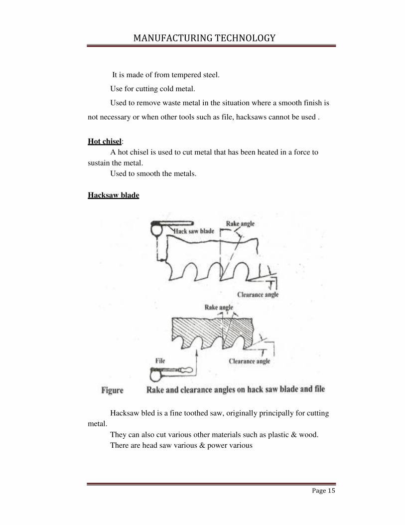
Hacksaw blade
metal.
Hacksaw bled
They can also
There are hea
MANUFACTURING TECHNOLOGY
of from tempered steel.
ting cold metal.
ove waste metal in the situation where a smooth
hen other tools such as file, hacksaws cannot be u
l is used to cut metal that has been heated in a forc
ooth the metals.
led is a fine toothed saw, originally principally for
lso cut various other materials such as plastic & w
ead saw various & power various
Page 15
th finish is
e used .
orce to
or cutting
wood.

MANUFA
When attache
tension.
The frames m
sizes. Blades are av
a standard hand hack
The pitch of t
hand blade & for lar
As hack-saw
As the blades
taken to prevent frac
Blades are ma
But for severa
their teeth, giving gr
On hack-saw
or away from the han
Resulting and
In normal use
bench, vice, the saw
Die:
MANUFACTURING TECHNOLOGY
hed to a C-shaped frame which holds a blade unde
may be adjustable to accommodate blades of diff
available in standardized lengths, usually 1011
or 1
ck-saw.
f the teeth can be anywhere from 14 to 32 per inch
arge power hack saw blade there are 3 tpi
w teeth are so small, they are set in a wave set.
es are normally quite brittle, so proper care should
acture of the blade.
made of carbon steel or low alloy steel.
eral decades now, hack-saw blades have used HSS
great improved cutting & tooth life.
w the blade can be mounted with the teeth facing
handle
nd cutting action on either pushes or pull stroke.
se, cutting vertically downwards with work held i
w blade Should be set to be face forward.
Page 16
der
ifferent
r 1211
for
ch for a
uld be
SS for
g toward
in a

MANUFACTURING TECHNOLOGY
Page 17
Die cutting is the posses of using die to shear weds of low strength
material such as rudder, tidier, cloth, plastic, sheet metal etc.
Die cutting can be done on either flat bed or by rotary process .
Rotary dry cutting is die cutting using a cylindrical die or a rotary
processes .
Dies are used to cut the external thread or the rod or pipe end.
Dies are made of high carbon steel or HSS .
The process of cutting external thread by dies is called dieing .
Sharing is also known as die cutting, is a process which cuts stock
without formation of chips or the off during or melting.
The die cutting action can be controlled by electric, hydraulic,
pressurized or manual surfaces.
Reamer:
� It is a multiple edge cutting tools.
� The process of enlarging the hole is called reaming.
� There are many different types reamer and there may
be designed for used as a hand tool or in a M/C tool such as milling
M/C or drill press.
� A typical reamer consists of a set of parallel straight or
helical cutting edge along the length of a cylindrical body
� Each cutting edge is grounded at a slight angle and with
slight undercut below the cutting edge
� This may be used to remove small amount of material.
� Reamers are made of high Carbon or Plain Carbon
Steel
Reamers ar of two types
� Hard Reamers
� Machine Reamers

MANUFA
Machining Process
Factors affect
The life of a
feed, depth of cut, c
and rigidity of the m
Cutting Speed:
The cutting
between the tool an
cutting edge of the to
It may be de
material. It is expres
Feed:
It is defined
cutting tool, relative
cutting speed directi
MANUFACTURING TECHNOLOGY
ss Parameters:
ecting tool life:
a tool is affected by many factors such as: cutti
t, chip thickness tool geometry, material of cutti
machine
g speed can be defined as the relative surfa
and the job or the amount of length that will
tool per unit of time.
defined as the speed which the cutting edge pass
essed in meters per min (mpm).
ed as the relation by small movement per cycl
ve to the workpiece in a direction which is usua
ction.
Page 18
tting speed,
tting fluid,
rface speed
ll pass the
ass over the
cle of the
ually to the

MANUFACTURING TECHNOLOGY
Page 19
Or
It is he distances the tools advances into or along the work piece. Each
time the tool point passes a certain position in its travel over the surface. It is
expressed as mm\tooth.
Depth of cut:
The depth of cut is the thickness of the layer of metal removed in one
cut or pass, measured in a direction perpendicular to the machined surface.
It is the vertical distance the tool advances into the work piece during
one revolution of job it is expressed in mm.
Selection of cutting speed, feed & depth of cut:
� Hard and strong materials require a lower cutting speed, soft & ductile
materials require higher cutting speeds.
� For light finishing cut – fine feed & higher speed roughing cut – low
feed & lower cutting speed.
� Large depth of cut – roughing operation
� Small depth of cut – finishing operation
� Cemented carbide, ceramics, satellite &
� Hss – high cutting speed tool
� Alloy or carbon steel tools – lower cutting speed.
Coolants & lubricants:
Cutting fixed sometimes referred to at lubricants or coolants are
liquids and gases applied to the tool and work piece to assist in the cutting
operations.
MANUFACTURING TECHNOLOGY
Page 20
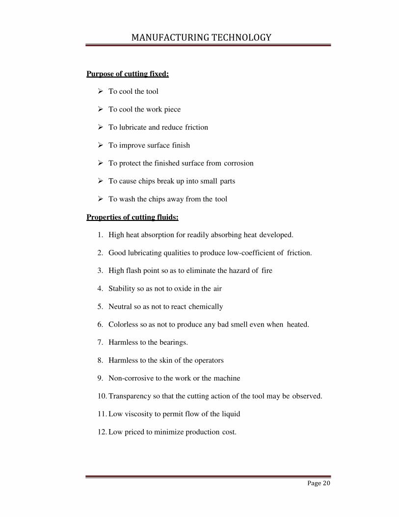
Purpose of cutting fixed:
� To cool the tool
� To cool the work piece
� To lubricate and reduce friction
� To improve surface finish
� To protect the finished surface from corrosion
� To cause chips break up into small parts
� To wash the chips away from the tool
Properties of cutting fluids:
1. High heat absorption for readily absorbing heat developed.
2. Good lubricating qualities to produce low-coefficient of friction.
3. High flash point so as to eliminate the hazard of fire
4. Stability so as not to oxide in the air
5. Neutral so as not to react chemically
6. Colorless so as not to produce any bad smell even when heated.
7. Harmless to the bearings.
8. Harmless to the skin of the operators
9. Non-corrosive to the work or the machine
10. Transparency so that the cutting action of the tool may be observed.
11. Low viscosity to permit flow of the liquid
12. Low priced to minimize production cost.
MANUFACTURING TECHNOLOGY
Page 21
Choice of cutting fluids:
1. Type of operation
2. The rate of metal removal
3. Material of the work piece
4. Material of the tool
5. Surface finish requirements
6. Cost of cutting fluid.
Type of cutting fluids:
Water:
Pure water is the best cutting fluid available because of its highest
heat carrying capacity. But water corrodes the material very quickly so
water containing alkali, salt or water-soluble additive but little or no oil or
soap are some times used as coolant.
Soluble oils:
These are emulsions composed of around 80% or more water, soap
& mineral oil. The soap acts as an emulsifying agent which breaks the oil
into minute particles to dispose them throughout the water. The water
increase the cooling effect and the oil provide the lubricating properties.
Straight oils:
The straight oils may be
a) Straight mineral oils, kerosene, low-viscosity petroleum fraction
such as mineral seal, or higher viscosity mineral oils
b) Straight fixed or fatty oils consisting animal, vegetable or synthetic
equivalent, lard oil etc.
c) They have both cooling and lubricating properties

MANUFACTURING TECHNOLOGY
Page 22
Mixed oils:
This is a co0mbination of strength mineral and strength fatty oil.
This makes oil excellent lubricant and coolant for anosmatic screw-machine
work.
Chemical additive oil: straight oil or mixed oil when mixed- up with
sulphur or chorine is known as chemical additive oil. Sulphur and chloral
are used to increase both lubricating and cooling qualities. These oils used
for machining tough, stivgy7 low carbon steels.
Chemical compounds: these compounds consists mainly of a rust
inhibitor, such as sodium nitrate, mixed with a high percentage of water.
Solid lubricants: stick waxes. And bar soaps are sometimes used as
lubricants.
Metal cutting and cutting tools : in the metal working industry the
various working processes fall into groups.
Not-cutting shaping – forgery, pressing, drawing
Cutting shaping – turning, drilling, milling.
Cutting tools
A cutting tool may be used either for cutting a part or for removing
chips.
Cutting tools are mainly divided into two groups.
� Single point cutting tool
� Multipoint cutting tool
A single point cutting tool consists of a sharpened cutting part
called its point.
Ex: lathes, slotting machines
Multipoint cutting tools have arrangement of two or more single
point tools as a unit.
Ex – milling cutting, broaching tool,twist drill.

MANUFA
Cutting tool nomen
It means sche
cutting tool.
Shank:
It is the main
Flank:
The surface o
called flank of the to
Heel:
It is the inter
Nose:
It is the point
intersection.
MANUFACTURING TECHNOLOGY
enclature:
hematic naming of the various parts and angles of
in body of the tool.
or surfaces below and adjacent to the cutting edg
tool.
tersection of the flank and the base of the tool.
nt where the side cutting edge and end cutting edg
Page 23
of a
dge is
dge
MANUFACTURING TECHNOLOGY
Page 24
Cutting edge :
It is the edge on the face of the tool which removes the metarial from
the work piece. The total cutting edge consists edge (major), end cutting
edge (minor) and the nose.
Face:
The surface against which the chip slides upward.
Base:
Tt is the undersice of the shank.
Rake:
It is the slope of the tap away from the cutting edge. Larger the rake
angle, the cutting force and power reduce.
Designation of cutting tools: there are two system to designate the tool
shape
1. American standards association system (ASA)
Or
American national standards institute (ANSI)
2. Orthogonal rake system. (ORS)
The various tool angles are:
1. Side cutting edge angle (Cs): (Lead angle)
The angle between the side cutting edge and side of the tool
shank
2. End cutting edge angle (Ce):
This is the angle between the end cutting edge and a line normal to
the tool shank

MANUFACTURING TECHNOLOGY
Page 25
Side relief angle:
It is the angle between the portion of the side flank immediately below
the side cutting edge and a line perpendicular top the base of the tool
measured at right angle to the side flank.
End relief angle
It is the angle between the portion of the end flank immediately below
the side cutting edge and a line perpendicular to the base of the tool measured
at right angle to the end flank.
Back rake angle:
It is the angle between the face of the tool and s line parallel to the
base of the tool and measured in a plane perpendicular to the side of the
cutting edge. The angle is +ve – If side cutting edge slopes downwards from
the point towards the shank.
-ve – if the slope of the side cutting edge is reverse.
Side rake angle :
It is the angle between the tool face and a line parallel to the base of
the tool and measured in a planer perpendicular to the base and side cutting
edge. This angle gives slope of the face of the top from the cutting edge.
The angle is – ve – if the slope is towards the cutting edge
+ve - If the slope is away from the cutting edge
Purpose of tool angles
Cs – It is the angle which prevents interface as the tool enters the
work material. This angle affects tool life and surface finish 150 top 300 is
kept for general machining.
Ce – It provides a clearance or relief to the trailing end of the cutting
edge to prevent rubbing or drag between the mechanical surface and the non
cutting part of the cutting edge 8 to 150 is satisfactory.

MANUFACTURING TECHNOLOGY
Page 26
These angles are provided so that the flank of the tool clears the
workpiece surface and there is no rubbing between them 5 to 150 is given.
Larger the rake angle smaller the cutting angle and lower the cutting
force and power
The rake angle is small for cutting har4d materials and large for
cutting soft ductile materials. It may be – ve or zero.
A flat cold chisel is a single point tool used at the branch and the
point is considered as wedge.
For mild steel a rake angle of 300 and wedge angle of 600 are
recommended
Using a cold chisel with no clearance angle, the loss through friction
is small as are cutting point is in contact with the metal
The force hammer below F is transmitted at approximately 900 to the
cutting face ac and these sets up shear stress across the shear plane ab.
If the hammer blow is heavy as , the metal will shear across the shear plane
and move up to the face ac as continuous chip.
The energy required to shear the metal will be the shearing force
along the shear plane and this force is proportional to the length of the shear
force is propotional to the length of the shear plane and the greater the energy
required to the shear of metal
A hack saw blade is a multi-point tool and has a very large number of
wedges like points each with its own rake and clearance angle.
The rake is necessary but too much rake makes the tooth weak
A large amount of energy would be lost in overcoming the frictional
forces set up if there is clearance.
The hollow space between each tool is sloped more sharply to give
the form if this would be too
Shallow it would be closed with chips of the metal being cut

MANUFACTURING TECHNOLOGY
Page 27
Taps are used for cutting internal threads on work materials. it
consists of a no of teeth arranged uniformly across the whole die body when
it rotates in a particular direction i.e clockwise or anticlockwise .
The rake angle is provided to reduce the shear forces during cutting &
less torque will be required to shear the metal. There is no provision for
clearance angle in the die.
It is a multi point cutting tool used for enlarging or finishing a
previously drilled or bore hole to give a good finish and accurate dimension.
It removes very small amount of material from the work piece.
MANUFACTURING TECHNOLOGY
Page 25
Lathe Machine
Chapter-3

MANUFACTURING TECHNOLOGY
Page 26
Lathe machine:
The lathe machine is the one of the oldest machine tools and came the
early tree lathe which was a device for rotating and machining a piece of
lathe between two adjacent trees. a rope would round the work with its one
end attached to a flexible branch of trees and end is pulled by a man to rotate
the job hard tools are used them.
Function of lathe machine:
The main function of lathe machine is to remove metal from a piece
of work to give it the required shape and size. The work is held securely and
rigidly on the machine and then turn against the cutting tools which is
remove metal from the work in the forms of chips.
Types of lathe:
� speed lathe:
o Wood working
o Centering
o Polishing
o Spinning
� Engine lathe:
o belt drive
o Individual motor drive
o Gear head lathe
� Bench lathe:
� Tool room lathe
� Caps & turret lathe
� Special purpose:
o Wheel lathe
o Gap bed lathe
o Turret lathe
o Duplicating lathe
� Automatic lathe:
MANUFACTURING TECHNOLOGY
Page 27
The speed lathe:
� It is the simplest of all types of lathe.
� It consists of a bed, headstock, a tailstock and a too post mounted on
an adjusted slide.
� There is a no feed box, lead screw or conventional type carriage.
� The tool is mounted on the adjustable slide and is fed into work purely
by hard control.
� Spindle speed is very high.(range from 1200 to 3600 rpm).
� This is used for word working, spinning, centering, polishing.
The engine lathe or centre lathe:
� The engine lathe in the early ware driven by steam engines
� It consists of bed, head stork, and tail stork.
� More robust head stock and contains mechanism for driving the
spindle at multiple speeds.
� Belt driving lathe – receives power from an overhead live shaft
� Individual motor drive- receiving power from an individual motor
� Gear head lathe –gets power from a constant speed motor.
The bench lathe:
� The small lathe mounted on a bench
� It consists of all the parts but small in size.
� It is used for small & precision work.
The tool room lathe:
� It is similar to engine lathe.
� It has spindle speeds ranging from very low to high up to 2500 rpm.
� It consists of chuck, taper turning attachment, thread charging dial,
steady rest, coolant etc.
� This is used for precision work on tools, dies, gases & for accuracy
works

MANUFACTURING TECHNOLOGY
Page 28
Capstan and turret lathe:
� This is the development over engine lathe.
� The tail stock is replaced by a hexagonal turret, on the face of which
multiple tools are fitted
� Several operations can be done on a work piece without resetting of
work or tools & a no. of identical parts can be produced in minimum
time.
Special propose lathe:
� They are used for special proposes.
� The Wheel lathe – for finishing journals &turning the thread on rail
road car and locomotive wheels gap bed lathe- to swing extra large
diameter pieces.
� T-lathe – for machining of motor for jet engines the axis of the lathe
bed is right angles to the axis of the head store spade.
� Duplicating lathe used for duplicating the shape of a flat or round
template on the work piece
Automatic lathe:
� These are high speed, heavy duty, mass production lathes with
complete automatic control.
� After the tools are set and the machine is started is performs
automatically all the operations to finish the job.
� The changing of tools, speed s and feeds are done automatically.
� After the job is complete, the machine will continue to repeat the
cycles producing identical parts.

MANUFACTURING TECHNOLOGY
Page 29
Specification of lathe :
� The height of the centres from the bed.
� The swing diametre over bed. This is the largest diameter of work
that will revolve without touching the bed and is twice the height of
the centre measured from the bed of the lathe.
� The length between the centers. This is the max height of work that
can be mounted between the lathe centres.
� The swing dia over carriage. This is the biggest dia of work that can
be less than the swing dia over bed. This is the maximum bar stock
will pass through hole of the headstock spindle .
� The length of the bed: This indicates the approx. floor space occupied
by the lathe
The work piece is held in a chuck or between centers and rotated its
axis at uniform speed .the within tool held in the tool post is fed in to the
work spices for a desired depth. the tool may be given linear motion in may
direction salve there is a relative motion between the work piece and tool ,
the material is removed the form of chips & desired shape is obtained .

MANUF
Different parts of a
1. Bed
2. Head stock
3. Tail stock
4. Carriage
5. Feed mechan
6. Screw cuttin
BED:
The be
iron. It is a
deflection an
carriage. On
ways. The ou
The guide wa
900
MANUFACTURING TECHNOLOGY
f a lathe :
anism
ing mechanism
bed is the base or foundation of the lathe. It is ma
a massive and rigid casting made in one piece
and vibrations. It supports the head stock, tail
n the top of the bed, there are two sets of slides
outer ways for carriage and inner ways for the t
ways may be flat and inverted –v having included
Page 30
ade of cast
ce to resist
il stock and
es or guide
e tail stock.
ed angle of

MANUF
Head stock:
The head stoc
of the lathe. It
multiple speeds.
The spindle o
It protrudes from
holding derives
nose is turned so
rotate the work p
live centre.
MANUFACTURING TECHNOLOGY
tock assembly is permanently fastened to the left
It provides mechanical means of rotating the
e of head stock is made of carbon or nickel chro
rom gear box and contains means for fast end
s like chuck, face plate, dog plats, live centred
so that face plate or chuck can be mounted on it
piece. Hollow spindle is tapered at the nose to re
Page 31
ft hand end
e work at
hrome steel.
nding work
ed spindle
it hold and
receive the

MANUF
Spindle is ho
which long bar s
max’m size of ba
Power is supp
MANUFACTURING TECHNOLOGY
hollow throughout its length throughout its lengt
r stock can be fed. The size of spindle hole deter
bar stock that can be machined
pplied from an electric motor or V-belt.
Page 32
gth through
ermines the
MANUF
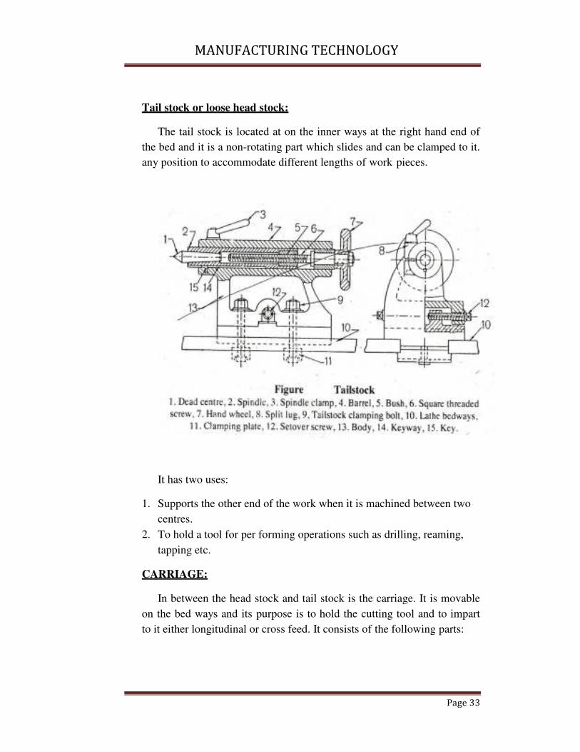
Tail stock or loo
The tail stock
the bed and it is a
any position to ac
It has two use
1. Supports the
centres.
2. To hold a too
tapping etc.
CARRIAGE:
In between th
on the bed ways
to it either longit
MANUFACTURING TECHNOLOGY
loose head stock:
ck is located at on the inner ways at the right ha
is a non-rotating part which slides and can be clam
accommodate different lengths of work pieces.
ses:
e other end of the work when it is machined betw
ool for per forming operations such as drilling, rea
the head stock and tail stock is the carriage. It is
ys and its purpose is to hold the cutting tool and
itudinal or cross feed. It consists of the following
Page 33
hand end of
amped to it.
tween two
reaming,
is movable
d to impart
ng parts:

MANUF
1. Saddle:
It is an
bed. It carries
2. Cross slide:
It is m
is to the cent
mixed by me
wheel or by p
MANUFACTURING TECHNOLOGY
an H-shaped cashing that fits over the outer wa
ies the corss-slide and tool post.
mounted on saddle. It provides cutting tool moti
ntre like of the lathe. This is known as cross sli
means of feed screw, which is controlled by a sm
power feed.
Page 34
ways of the
otion which
slide can be
small hand

MANUF
3. Compound r
It is m
post. It has a
axis. It can b
means of a s
graduated dia
4. Tool post:
It is m
The tool pos
clamped in a
desired angle
way
MANUFACTURING TECHNOLOGY
rest:
mounted on the top of the cross slide. It support
s a graduated base and can be swiveled around
be swivelled around a vertical axis. It can be m
a screw which is controlled by a small hand w
ia & not by power feed.
mounted on the top of the compound rest to hold
ost can be moved on the compound rest and
any position. It can be rotate also to hold the
le.1. single tool post 2. Four bolt 3. Open side
Page 35
orts the tool
d a vertical
e moved by
wheel and
old the tool.
and can be
he cutter in
de 4. Four

MANUF
MANUFACTURING TECHNOLOGY
Page 36

MANUF
5. Apron:
lathe is calle
operating the
contains frict
which is close
FEED MECHA
Feed is the di
revolution of he
cross and angula
Longitudinal fee
When the to
termed as longit
and is effected by
Cross feed:
When the to
termed as cross
movement of cro
MANUFACTURING TECHNOLOGY
The portion of the carriage which extends in
lled apron. It contains the gears, clutches. And l
the carriage by hand or power feeds. The ap
iction clutches for automatic feed of a split nut o
osed over for cutting screw threads.
ANISM:
distance the tool advances into the work piece thr
head stock spindle a lathe tool has 3 types- lon
lar.
feed:
tool moves parallel to the lathe axis, the mov
gitudinal feed. It is used in cylindrical turning o
by movement of carriage.
tool moves parallel to the lathe axis, the mov
ss feed. It is used in facing operation & aff
ross slide.
Page 37
in front of
d levers for
apron also
t or half nut
through one
ongitudinal,
ovement is
operations
ovement is
affected by

MANUFACTURING TECHNOLOGY
Page 38
Angular feed:
When the tool moves at an angle to the lathe axis, it is termed as
angular feed. It is used in taper turning and affected by movement of
compound rest.
Angular feed is hand operated where cross feed & longitudinal feed
can be both hand & power operated.
Third cutting mechanism:
The rotation of the head screw is used to transverse the tool along
were to produce screw thread. The half nut mechanism makes the carriage to
engage or disengage or disengage with the lead screw. The two halves of the
nut are connected in the cam slots in a circular disc by two pins. When the
disc is rotated by a hand lever attached to it, the pins being guided in the cam
slots serve to open or close the split nuts and thus engages or disengages with
the lead screw.
The half nuts slide within the guide or frame. Closing the half nuts
causes the carriage to move a fixed distance for each revolution of the
spindle. The direction in which it moves depends upon the position of the
feed reverse lever on the head stock. The split nut is used only for thread
cutting and never for any other operation.
Lathe operation:
Lathe operations are performed by following methods.
Operations which are performed in a lathe either by holding the work
piece between centers or by a chuck:
1. Straight turning
2. Shoulder turning
3. Chamfering
4. Thread cutting
5. Facing
6. Knurling
7. Filling
8. Taper turning

MANUFACTURING TECHNOLOGY
Page 39
9. Eccentric turning
10. Polishing
11. Grooving
12. Spinning
13. Spring winding
14. Forming
Operations which are performed by holding the work by a chuck or a
face plate :
1. Drilling
2. Reaming
3. Boring
4. Counter boring
5. Taper boring
6. Internal thread cutting
7. Tapping
8. Under cutting
9. Parting off
Operations which are performed by using special attachments:
1. Grinding
2. Milling
Facing:
Facing is the operation of for generation flat surface perpendicular to
the rotational axis of spindle. The tool is fed to the axis of rotation of the
work piece. A properly ground facing tool is used. A regular turning tool
may also be used. a spindle speed is selected and the lathe is started. The tool
is brought in to clean stock from the centre and fed out word by hand. Feed is
given by cross slide.
Turning:
MANUFACTURING TECHNOLOGY
Page 40
Turning in lathe is to remove excess material from the work piece to
produce a cone-shaped or a cylindrical surface.
Straight turning:
The work is turned straight when it is made to rotate about the lathe axis,
and the tool is fed parallel to the lathe axis. It produces a cylindrical surface
by removing excess metal from the work piece.
After facing the ends and drilling the centre, the job is
carefully mounted between the centres using a lathe dog attached to the
work piece, the bent tail of the dog fitting into the slot provided on the
catihplat. A properly ground a right hand turning tool selected. The
machine is started after the work piece and tool is properly set and correct
spindle speed is determined.
The automatic feed is engaged to move the carriage to the
desired length, then the feed is dis engaged and the carriage is brought
back to the starting position. The process is repeated until the job is
finally finished after two or three similar cuts.
There are two kinds of cuts in a machine shop work.
1. Roughing cut or rough turning.
2. Finishing cut or finish turning.
Rough turning:
It is the process of removal of excess material from the work piece in
a machine time by applying high rate of feed and heavy depth of cut. The
doc is from 2 to 5 mm & feed rate is 0.3 to 1.5 mm per over.
Finish turning:
It requires high cutting speed, small feed and a very small depth of
cut to generate a smooth surface. The doc is from 0.5 to 1 mm & feed 0.1 to
mm per rev.
Shoulder turning:
When a work piece having different diameters is turned, the surface
forming the step from one diameter to other is called shoulder turning

MANUFACTURING TECHNOLOGY
Page 41
The principle of thread cutting is to produce a helical groove on a
cylindrical or conical surface by feeding the tool longitudinal when the job
is revolved between centres or by a chuck. The longitudinal feed should be
equal to the pitch of the thread to be cut per revolution of the work piece.
The lead screw of lathe, through which saddle receives its traversing
motion, has a definite pitch. A definite ratio between the longitudinal feed
and rotation of the headstock spindle should therefore be found out. So that
the relative speeds of rotation of the work and the lead screw will result in
the cutting of a screw of the desired pitch.
This is affected by change gears arranged between the spindle and
the lead screw or by the change gear mechanism or feed box used in a
modern lathe where it provides a wider range of feed and the speed ratio
can be easily and quickly changed
Taper Turning:
A taper may be defined as a uniform increase or decrease in diameter
of a piece of work mannered along its length.
In lathe taper turning means to produce a conical surface
by gradual reduction in dia from a cylindrical work piece. The amount of
taper is specified by the ratio of the difference in dia of taper to its length let
it be denoted by k and termed as concity,
K = D-d/l
There are different methods for taper turning in lathe:
1. By a broad nose tool.
2. By setting over the tail stock centre.
3. By swivelling the compound rest
4. By a taper turning attachment.
5. By combining longitudinal feed & cross feed in a special lathe.

MANUF
Taper turning in a
Abroad nose
half taper angle, an
surface. The half an
The work is held in a
It is used to tu
Taper turning by se
MANUFACTURING TECHNOLOGY
a form tool:
se tool having straight cutting edge is set on to th
and is feed straight into the work to generate
angle of taper will correspond to (90-SCEA) of
a chuck or clamped on a face plate.
turn short length of taper only.
setting over the tailstock:
Page 42
the work at
e a tapered
of the tool.

MANUF
The axis of r
lathe axis and the to
the axis of rotation
taper.
This is done b
from the operation b
This is used f
By swivelling the co
In this metho
axis and feeding the
The tool mou
base, graduated in
desired angle the co
lathe axis to turn a st
MANUFACTURING TECHNOLOGY
rotation of the work piece is shifted at an ang
tool is fed parallel to the lathe axis. The angle
n of the work piece is shifted is equal to half an
by the tail stock is made to slide on its base or aw
by a set over screw.
d for turning small taper (not exeed 80) on long jo
compound rest:
hod the taper is formed by rotating the work piec
e tool at an angle to the axis of rotation of work p
ounted on the compound rest is attached to a
n degree, which may be swivelled and clampe
compound rest car be swivelled at 45 on either s
steep taper. The angle is determined by
Page 43
ngle to the
le at which
angle of the
away
jobs.
ece on lathe
piece.
a circular
ped at any
r side of the
MANUFACTURING TECHNOLOGY
Page 44
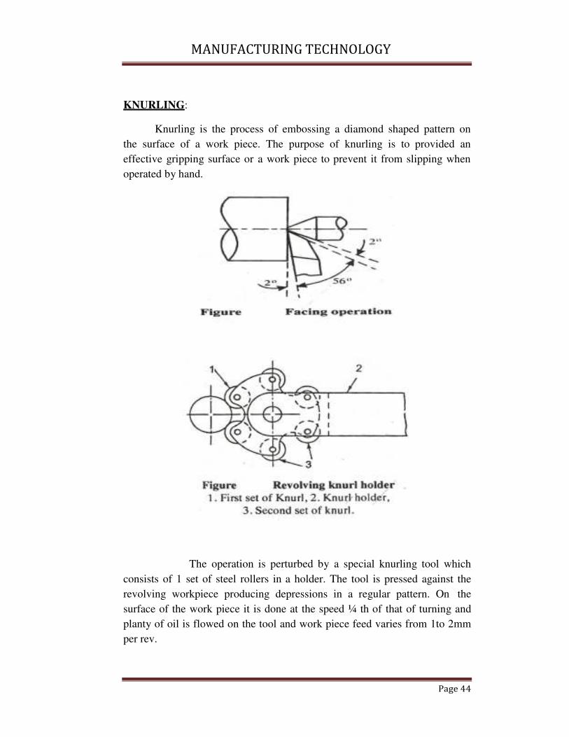
KNURLING:
Knurling is the process of embossing a diamond shaped pattern on
the surface of a work piece. The purpose of knurling is to provided an
effective gripping surface or a work piece to prevent it from slipping when
operated by hand.
The operation is perturbed by a special knurling tool which
consists of 1 set of steel rollers in a holder. The tool is pressed against the
revolving workpiece producing depressions in a regular pattern. On the
surface of the work piece it is done at the speed ¼ th of that of turning and
planty of oil is flowed on the tool and work piece feed varies from 1to 2mm
per rev.

MANUFACTURING TECHNOLOGY
Page 45
Parting off:
Parting off is the operation of cutting a work piece after it has been
machined to the desired size & shape the job rotated on a chuck or face
plate at half the speed that of turning and a narrow parting of tool is feed to
the lathe axis by. Hand feed. The feed varies from 0.07 to 0.15 mm per rev.
And depth at let ranges from 3 to 10 mm .
Internal machining:
Drilling:
Drilling is the operation of production a cylindrical hole in a work
piece by rotating cutting edge of a cutter known as drill .
The work piece is revolved in a chuck or faceplate and the drill is
held in the tailstock drill holder or in a drill chuck. Feeding is effected by
the movement of the tail stock spindle (adopted for regular shaped work
pieces)
The drill is held and driven by a drill chuck attached to the headstock
spindle and the work is held against a pad supported by the tailstock
spindle. Feeding is effected by the movement of the tailstock spindle
(adopted for irregular shaped work pieces

MANUFACTURING TECHNOLOGY
Page 46
Boring:
It is the operation of enlarging and truing a hole produced by
drilling, punching, casting co-forging the
The work is revoluted in a chuck or a face plate and the tool which is
flitted to the tool post is fed in to the work . One piece forged tool is used for
boring small hole , whereas a boring bar with a tool bit attached to it is
suitable for machining a large hole the doc is giver by the cross slide screw
and the fade is feeder by the longitudinal travel of the carriage .
The work is clamped on the carriage and a boring bar holding the
tool is supported between the centres made to revolute. Longitudinal
movement of the carriage provides feeding movement and the doc is given
by adjusting the position of the tool insert.
Internal thread to external forced cutting operation , the different
being in the carriage provides feeding movement and the doc is given
adjusting the position of the tool insert .
Internal thread cutting:
It is similar to external thread cutting operation , the different being
is the tool used . the tool is similar to boring tool with the cutting edges
ground to the shape conforming to the type of thread to be cut the hole is
first bored to the root dia of the thread for cutting metric to read the
compound slide is swivelled 30� to words the headstock . the tool is fixed on
the toolpost or on the boring bar after strive it at tught angle to the lathe axis

MANUFACTURING TECHNOLOGY
Page 47
, using a trove gauge the do is given by compound slide and the to read is
finished in the usual manner.
Safety measures during machining:
Some safety precautions should be needed while working on lathe.
� Before operating the machine, one should fully understand its
operations controls and how to stop it.
� All gears and gear ends of the lathe should be properly guarded.
� Safety goggles are preferred to avoid damage to eyes by flying
chips.
� Avoid wearing rings, bracelet or watch.
� Machine should not be left running and operator should be alert
during a job.
� Before starting a lathe spindle by power, spindle should be rotated
by one revolution by hand to make it sure that no fouling is there.
� Safe distance from revolving chuck should be maintained.
� Tools and instruments should not be placed over lathe bed.
� Sliding parts of the lathe should be cleaned and lubricated
periodically.
� Chips should never be removed by hand. It can be removed by
brush.
� Before starting the machine, the work should be clamped
properly.
� Before moving the carriage, the carriage clamping screw should
be unlocked.
� On hearing unusual noise, machine should be stopped
immediately and should not be operated till the fault is clear.

MANUFACTURING TECHNOLOGY
Page 48
Capstan & Turret lathes:
A capstan or a turret lathe is a production lathe used to
manufacture any number of identical pieces in the minimum time.
The main feature is the six sided block mounted on one end of the
bed replacing the normal tailstock six tools can be mounted at on
cross slide two tool posts are mounted, one in the font and the
other in the rear. Each one can hold four tools .Thus the total
carrying capacity is a maximum 14 tools
Difference between CAPSTAN &TURRET and an ENGINE LATHE
CAPSTAN &TURRET ENGINE LATHE
1. The head stock possesses
wider range of speeds and in
heavier in construction it
require 15 hp power to drive
the spindle.
1. It requires 3hp to drive the
spindle.
2. The tool post mounted or the
cross slide is a four way & a
rear tool post is mounted on
the rear side which also holds
4 tools.
2. In engine lathe one tool can
be mounted at one time for
different operation.
3. In turret lathe, the tail stock is
replaced by a turret which is a
hexagonal block which
contains 6 tools on each face.
3. It can accommodate one tool
of limited size.
4. The feed movement of each
tool set on square or
hexagonal turret is regularity
by stops & feed strips.
4. The feed movement is given
by hand.
5. Combination cuts can be
taken by mounted two or
more tools on the same face
of the turret.
5. Combination cuts cannot be
done.
6. The labour cost is less. 6. Labour cost is more.

MANUFACTURING TECHNOLOGY
Page 49
7. The threads are cut by
die heads & taps.
7. The threads are cut by lead
screws Centre lathe is
suitable for odd jobs having
different shapes & sizes.
8. Turret lathes are suitable for
producing large no. Of
identical pieces.
8. The threads are cut by lead
screws.
Difference between capstan & turret lathe:
Capstan lathe Turret lathe
1. Its turret head is mounted in
slide, which moves on the
guide ways produced on the
saddle.
2. For feeding the tool to the
work, the saddle is fixed at
convenient distance from the
work.
3. It is suitable for smaller size
& lighter jobs. It is not
suitable for heavy cutting
condition.
4. It is suitable to work for
smaller bar upto 60 mm dia.
5. The turret head may
hexagonal or circular.
6. It is smaller in size compound
to turret lathe.
7. The tool traverse is faster and
offer less fatigue to the hands
of the operator.
1. Its turret to head is mounted
directly on the saddle.
2. For feeding the tool to the
work, the entire saddle unit is
moved.
3. It is suitable for long and
heavy work and severe cutting
condition.\
4. It is used to work for large size
bar upto 200mm dia.
5. Turret head is hexagonal.
6. It is large in size as compared
to capstan lathe.
7. The tool feeding is relatively
slower and provide more
fatigue to operator hands.

MANUFA
The capstan or ram
The capstan
turret on ram or sho
ways. the feeding m
right and when the
and the toll mounte
machine is lighter in
diameter.
MANUFACTURING TECHNOLOGY
am type lathe:
n or ram type turrent or capstan lathe carries a h
hort slide,the ram slide longitudinally on a sadd
movement is obtained when the ram moves fro
e ram moved backward the turret indexes auto
ted on the next face comes into operation. Thi
in construction and is suitable for machinery ba
Page 50
a hexagonal
ddle on bed
from left to
utomatically
his type of
bar of small
MANUFA
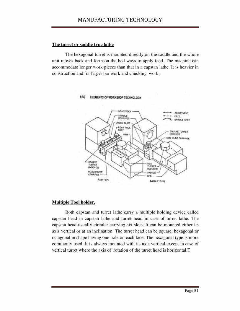
The turret or saddl
The hexagona
unit moves back and
accommodate longer
construction and for
Multiple Tool holde
Both capstan
capstan head in cap
capstan head usually
axis vertical or at an
octagonal in shape h
commonly used. It i
vertical turret where
MANUFACTURING TECHNOLOGY
dle type lathe
nal turret is mounted directly on the saddle and
nd forth on the bed ways to apply feed. The ma
ger work pieces than that in a capstan lathe. It is
or larger bar work and chucking work.
lder.
an and turret lathe carry a multiple holding dev
apstan lathe and turret head in case of turret l
lly circular carrying six slots. It can be mounted
an inclination. The turret head can be square, hex
having one hole on each face. The hexagonal typ
t is always mounted with its axis vertical except
re the axis of rotation of the turret head is horizon
Page 51
d the whole
achine can
is heavier in
evice called
t lathe. The
ed either its
exagonal or
ype is more
t in case of
ontal.T

MANUFA
Parts of capstan an
Bed:
The bed is lo
on which the carria
strength, rigidity and
MANUFACTURING TECHNOLOGY
and turret lathe:
longer box like casing provided with accurate gu
iage and turret slid are mounted. It is designed
nd permanency of alignment under heavy duty ser
Page 52
guide ways
d to ensure
services.

MANUFACTURING TECHNOLOGY
Page 53
Headstock:
It is similar to engine lathe in construction. It is larger & heavier in
construction and wider range of speeds speed may rang form 30 to 2000rpm
two types of headstocks.
a) Electric head - variable speed motor is mounted.
b) All geared heads - wider range of speeds
The spindle is hollow and bar stock can be fed thorough a collar chuck .
Gross slide & saddle:
There are two types of slides used in turret lathe
� Conventional type
� Slide hunk type
The conventional type of Carriage Bridge the gap between the front
and rear bed wage
The slide hunk type carriage is generally fitted with heavy duty turret
lathe. Large diameter of work pieces can be swing over bed. The
longitudinal movement of each tool may be regulated by using stop bars or
shafts set against the stop fitted on the bed and carriage. The stops are set so
the each tool will feed into the work to desired length the stop bars are
indexed by hand
The turret saddle and auxiliary slide :-
The turret saddle bridges the gap between two bed ways. The
hexagonal turret is mounted o9n the auxiliary slide. In turret lathe, the turret
is directly mounted on the top of the saddle.
The turret is a hexagonal shaped tool harder intended for six or more
tools. The centre line of each hole is coincides with the axis of the lathe. Six
stop bars are mounted on the saddle which restricts the movement of each
tool mounted on each face of turret to be fed predetermined amount. After
one operation the turret is brought backward from the spindle nose the turret
indexes automatically.
MANUFA
Capstan and turret
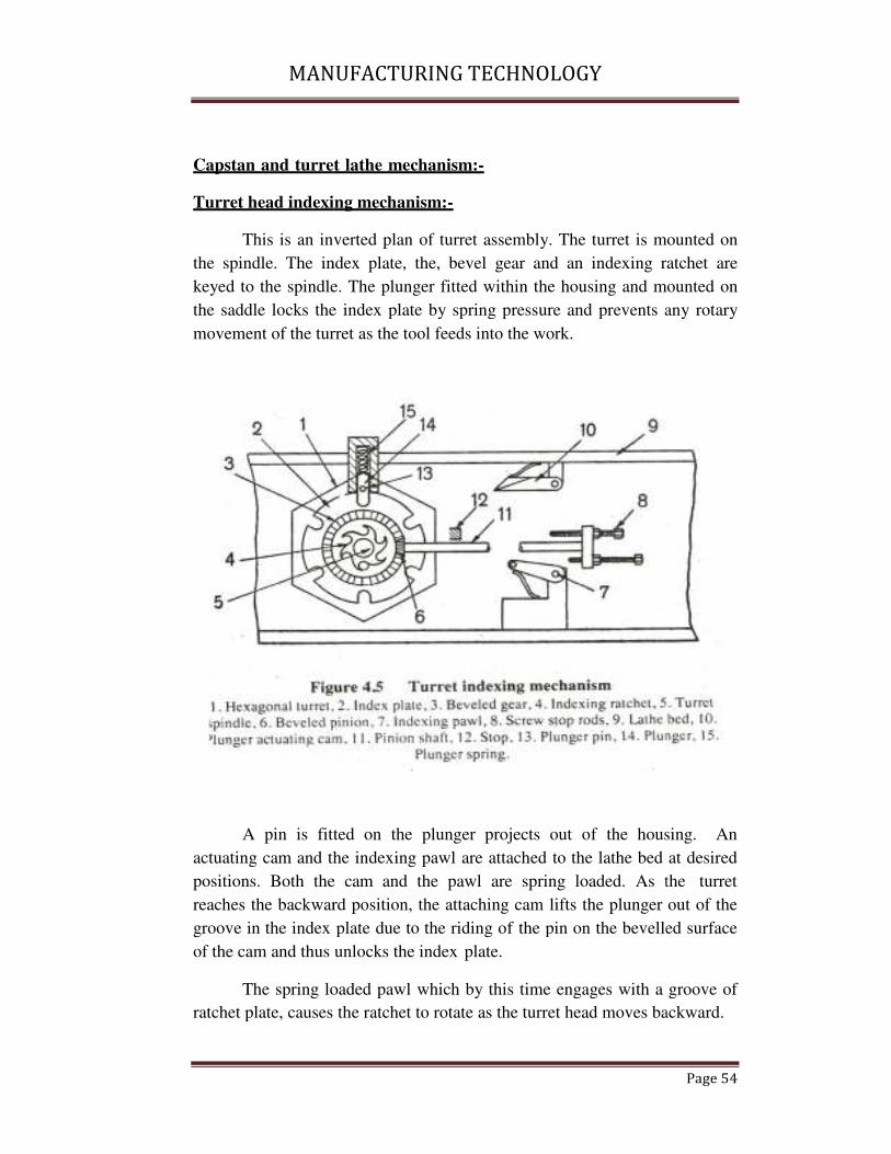
Turret head indexi
This is an inv
the spindle. The in
keyed to the spindle
the saddle locks the
movement of the tur
A pin is fitt
actuating cam and th
positions. Both the
reaches the backwar
groove in the index
of the cam and thus u
The spring lo
ratchet plate, causes
MANUFACTURING TECHNOLOGY
ret lathe mechanism:-
xing mechanism:-
inverted plan of turret assembly. The turret is mo
index plate, the, bevel gear and an indexing ra
le. The plunger fitted within the housing and mo
he index plate by spring pressure and prevents a
urret as the tool feeds into the work.
fitted on the plunger projects out of the hous
the indexing pawl are attached to the lathe bed
he cam and the pawl are spring loaded. As t
ard position, the attaching cam lifts the plunger o
x plate due to the riding of the pin on the bevelle
s unlocks the index plate.
loaded pawl which by this time engages with a
es the ratchet to rotate as the turret head moves ba
Page 54
mounted on
ratchet are
mounted on
s any rotary
using. An
d at desired
the turret
r out of the
lled surface
a groove of
backward.

MANUFACTURING TECHNOLOGY
Page 55
When the index plate or turret rotates through one sixth of revolution, the pin
and the plunger drops out of the cam and the plunger locks the index plate at
the next groove.
The turret is thus indexed by one sixth of revolutions and again
backed into the next position automatically. The turret holds the next tool is
now fed forward and the pawl is released from the ratchet plate by the
spring pressure.
The bevel opinion meshes with the bevel gear mounted on the turret
spindle. The extension of the pinion shaft carries a plate holding six
adjustable stop rods. As the turret rotates through one sixth of the revolution
, the bevel gear causes the plate to rotate.
The ratio of the teeth between the pinion and the gear are so chosen
that when the tool mounted on the face of the turret is indexed to bring it to
the cutting position, the particular stop rod for controlling the longitudinal
travelling of the tool is aligned with the stop.
The setting of the stop rods for limiting the feed of each operation
may be adjusted by unscrewing the lock nuts and rotating the stop rods on
the plate. Thus, six stop rods may be adjusted for controlling the
longitudinal travel of tools mounted on six faces of the turret.
Bar feeding mechanism:-
On the capstan and turret lathes, some arrangements is need to be feed
the bar stock through the collet or chuck after each finished work piece is
parted off. Bar may be fed by hand also but has a safety measure one has to
stop the machines first for every feeding of bar. It also wastes lot of time.

MANUFA
In this metho
collect without stopp
A bar feeding
of lathe. Bar is fed
stock passes through
connected with a sle
Under the act
At the end of the par
length of the bar. A
control lever, the ba
and strike with the b
The bar stop
the required bar len
operated to close the
MANUFACTURING TECHNOLOGY
hod the bar is push forward as soon as it release
pping the lathe.
ng mechanism is fitted with a capstan lathe is the
d against the rotating sleeve and the collet chuck
gh the spindle of the collet chuck. One end of th
leeve and the other end is attached with a weight.
action of the weight, the bar moves towards the he
arting off operation on the job. It is needed to fee
. As soon as the collet is opened by operating
bar is release and is automatically rushes out of
bar stop.
p mounted on the capstan head for the purpose
ength projecting out of the colet. The colet leve
he collet and hold the bar tightly.
Page 56
se from the
he back side
ck. The bar
the rope is
ht.
head stock.
eed the new
g the Colet
of the collet
e of getting
ver is again

MANUFACTURING TECHNOLOGY
Page 57
Tooling layout:
The tool layout for a job constitute the predetermined plan for the
order and method of machining operation necessary to produce it. For
preparation of the layout, it is necessary to have a finished drawing of the
part to be produce. The tool layout consists of two steps: preparation of
operation sheet.
Sketching the plan showing various tolls fitted into the turrent faces
and the cross slides, in proper sequence.
Production of hexagonal bolts:-
Operation no. description
operation
of tool position tools
1 Hold in collet 1st
position
turret Bar stop
2 Turn to 16 mm
dia
2nd
position
turret Roller steady bar
turning tool
3 Form end of the
bolt
3rd
position
turret Roller steady bar
ending tool
4 Screw 16 mm 4th
position
turret Self opening die
head with chasers
for 16 mm
5 Chamfer Front cross slide
tool past
Chamfering tool
6 Parting off Rear tool post Parting off tool
For bush:-
Sl no Sequence
operation
of Machine shop Tools / gauges
1 Fixed end
deep
2mm Turret
position1
(rear slide)
lathe Bar ending tool
2 Feed out bar stop Position 2 Bar stop
3 Stop for drilling Position 3 Centre drill
4 Drill hole 10 mm Position 4 Drill 10 mm dia,

MANUFACTURING TECHNOLOGY
Page 58
dia, and rough turn
16.5dia×36 mm
rough
tool
turning
5 Finish turn to 16.10
mm dia, bore 11.5
dia × 36 mm and
chamfer 0.3×45°
Position 5 Finish turn tool,
chamfering tool
and boring tool
³ Rough ream 11.8
mm dia×36 mm
Position 6 Reaming
rough
toll
7 Finish
11.8mm
mm
ream
dia × 36
Position 7 Reaming
finish
tool
8 Cut off to 31 mm
length
Position 8 Parting off tool
9 Chamfer other end
0.3×45°
Upright drill Chamfering tool
10 Drill oil hole Upright drill Drill 2mm
11 Cut oil grooves Special machine Groove cutter
12 Grind to 16 mm dia Cylindrical
grinder
Finish
wheel
grading
13 inspect Inspection
department
Limit gauges
1. Feed the bar stock to stop
2. Turn 14 mm dia with box tool
3. Turn 14.28 mm dia with box tool
4. Round end with roller steady ending tool
5. Centre with centre drill
6. Cut threads with die head
7. Form 17 mm dia and chamfer with tool from front square slide
8. Part off with cut of tool in rear tool

MANUFACTURING TECHNOLOGY
Page 59
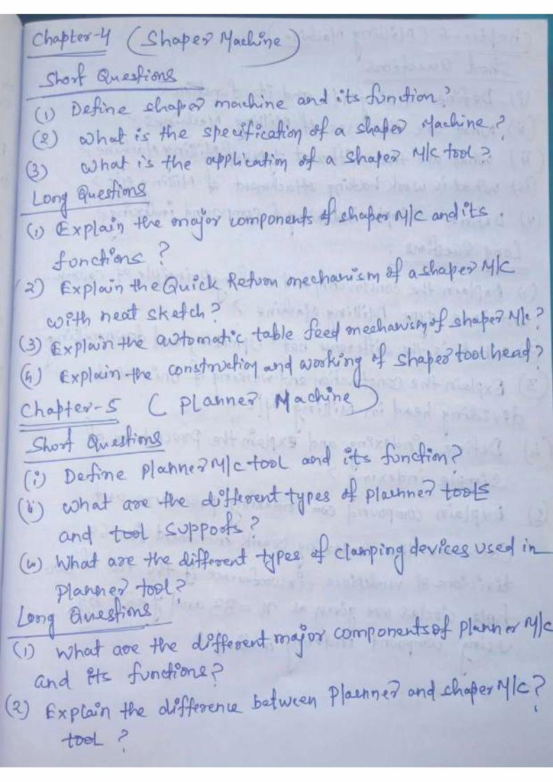
Shaper
Chapter-4
Shaper:-
The shaper is a reciprocating type of machine tool intended to produce
flat surfaces. The surface nay be horizontal, vertical or inclined
Working principle:-
The job is fixed rigidly in a suitable vice or directly clamped on the
machine table. The tool is held in the tool post mounted on the ram of the
machine. This ram reciprocates to and fro , and in doing so , makes the tool
to cut the material in the forward stroke. No cutting takes place during the
return stroke of the ram. It is called idle stroke. The job is given an intended
feed, in a direction normal to the line of action of the cutting tool.

MANUFACTURING TECHNOLOGY
Page 60
Types of shapers:-
1. According to the type of mechanism used for giving reciprocating
motion to the ram.
a. Crank type
b. Geared type
c. Hydraulic type
2. According to the position and travel of ram .
a. Horizontal type
b. Vertical type
c. Travelling head type
3. According to the type of design of the table
a. Standard shaper
b. Universal shaper
4. According to the type of cutting stroke
a. Push type
b. Draw type
Specification of shaper:-
1. Maximum length of stroke(175-900mm)
2. Maximum horizontal travel of table
3. Maximum vertical travel of table
4. Maximum distance from table to ram
5. Tool box, vertical adjustment
6. Length and width of the table
7. Numbers and range speeds available
8. Numbers and range feeds available
9. Horse power and speed of driving motor
10. Weight of the machine and floor space required

MANUFACTURING TECHNOLOGY
Page 61
Crank shaper:-
This a most common type of shaper. It uses a crank mechanism to
change circular motion of a large bull gear into reciprocating motion of the
ram
Geared type:-
The reciprocating motion is effected by means of rack and pinion
Hydraulic shaper:-
The reciprocating motion is obtained by hydraulic power.
Horizontal shaper:-
The ram reciprocates in a horizontal axis
Vertical axis:-
The ram reciprocates in a vertical axis
Travelling head shaper:-
The ram reciprocates and moves crosswise to give required feed
Standard or plain shaper:-
The table has two movements, vertical and horizontal to give the
feed
Universal shaper:-
In addition of the two movements, the table can be swivelled about
on axis parallel to the ram ways.
Push type:-
The most general type of shaper used in common practice . the metal
is removed when the ram moves away from the column
Draw type shaper :-
The metal is removed when the ram moves towards the column of
the machine, draws the work towards the machine. The tool set is reversed
direction to that of a standard shaper.

MANUFAC
DIFFERENT PAR
BASE:-
The base pro
equipments present a
it is made of cast iro
can be bolted to the f
Column(housing):-
The column
base. It houses the r
top of the column
movement of the ram
MANUFACTURING TECHNOLOGY
RTS OF A SHAPER:-
provides stability for the shaper as it supports
t as well as absorb the forces coming due to the
iron and have a necessary arrangements of bolts
e factory floor.
-
n of the shaper is a hollow casting and is mount
e ram driving mechanism. For the ram and tabl
n, necessary guide ways are provided for t
am and the front vertical face is for cross rail.
Page 62
ts all other
the cutting .
lts so that it
nted on the
ble, on the
the linear

MANUFACTURING TECHNOLOGY
Page 63
Cross rail:-
The cross rail is mounted on the front vertical guideways of the
column. It has two parallel guide ways on its top vertical plane that are
perpendicular to the ram axis. The table may be raised or lowered to
accommodate different sizes of job by rotating elevating screw.
Saddle:-
The saddle is mounted on the cross rail which holds the table . on its
top crosswise movement of the table is powered by rotating cross feed
screw.
Table:-
The work table of a shaper is fastened to the front of the column. The
table is provided T-slots for mounting the work pieces. The table can be
moved up and down and crosswise by cross rail and saddle. Jobs can be
held by vice.
Ram:-
The ram is a reciprocating member of the shaper. It is
semicylindrical in form and heavily ribbed inside to make more rigid. It
slides on the guideways of the column. A single point cutting tool is
fastened in the tool post.
Tool head:-
The single point cutting tool is held in the tool post. The tool head
holds the tool provides vertical and angular feed movement and allows the
tool to have an automatic relief during return stroke. The vertical side of the
tool head has a swivel base which is held on a circular seat on the room.
The swivel base is graduated in degrees so that the vertical slide may
be set perpendicular to the work surface at any desired angle. By rotating
the down feed screw handle, the vertical slide carrying the tool executes
down feed or angular feed movement while machining vertical or angular
surface.
The amount of feed or depth of cut may be adjusted by a micrometer
dial on the top of the down feed screw. Apron consisting of clapper box,

MANUFACTURING TECHNOLOGY
Page 64
clapper block and tool post is clamped upon the vertical slide by a screw.
By releasing the clamping screw , the apron may be swivelled upon the
apron swivel pin either towards left or towards right w.r.t the vertical slide.
This arrangements is necessary to provide relief to the tool while making
vertical or angular cuts.
The two vertical walls on the apron called clapper box houses the
clapper block which is connected to it by means of a hinge pin. The tool
post is mounted upon the clapper block.
On the forward cutting stroke the clapper block fits securely to the
clapper box to make a rigid tool support on the return stroke a slight
frictional drag of the tool on the work lifts the block out of the clapper box
a sufficient amount preventing the tool cutting edge from dragging and
consequent wear. The work surface is also prevented from any damage due
to dragging.
Shaper mechanism:-
The metal is removed in the forward cutting stroke, while the return
stroke no matal is removed during this period.
To reduce the total machining time it is necessary to reduce time taken
by the return stroke. The shaper mechanism should be so designed that it
can allow the ram holding the tool to move at comparatively slower speed
during the forward cutting stroke and during the return stroke the ram move
faster rate to reduce the idle return time. The mechanism is called quick
return mechanism.
1. Crank and slotted mechanism
2. Whitworth quick return mechanism
3. Hydraulic shaper mechanism
Crank and slotted link mechanism:-
The motion or power is transmitted to the bull gear through a pinion
which receives is motion from an individual motor or overhead line shaft
through speed control mechanism. Speed can be changed by shifting gears.
A radial slide is bolted to the centre of the bull gear , carries a sliding
block into which the crank pin is fitted . rotation of the bull gear causes the

MANUFACTURING TECHNOLOGY
Page 65
crank pin to rotate at a uniform speed. Sliding block which is invented on
the crank pin is fitted within the slotted link. The slotted link is pivoted at
its bottom end attached to the frame of the column. The upper end is forked
and connected to the ram block by a pin.
As bull gear rotates causes the crank pin to rotate, the sliding block
fastened to the crank pin will rotate on the crank pin circle, and at same
time will move up and down in the slot giving a rocking movement which
is communicated to the ram. The rotary motion of the bull gear converted to
reciprocating movement of the ram.
When the link is in the position PM.ram will be at the extreme
backward of its stroke.
When at PN – extreme forward position PM
&PN are tangent to the crank pin circle.
C1C2⇨ forward cutting stroke
C2 C1 ⇨ return stroke
MANUFAC
It is clear tha
The angular velocit
rotates at uniform sp
Generally varies 2:1
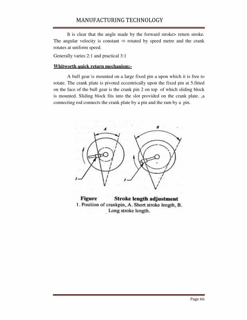
Whitworth quick r
A bull gear is
rotate. The crank pla
on the face of the bu
is mounted. Sliding
connecting rod conn
MANUFACTURING TECHNOLOGY
that the angle made by the forward stroke> retu
city is constant ⇨ rotated by speed metre and
speed.
:1 and practical 3:1
return mechanism:-
r is mounted on a large fixed pin a upon which it
plate is pivoted eccentrically upon the fixed pin
bull gear is the crank pin 2 on top of which slid
ng block fits into the slot provided on the crank
nnects the crank plate by a pin and the ram by a p
Page 66
turn stroke.
d the crank
it is free to
n at 5.fitted
liding block
nk plate. ,a
pin.
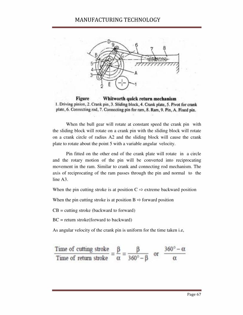
MANUFAC
When the bu
the sliding block wi
on a crank circle of
plate to rotate about
Pin fitted on
and the rotary mo
movement in the ram
axis of reciprocating
line A3.
When the pin cutting
When the pin cutting
CB = cutting stroke
BC = return stroke(f
As angular velocity o
MANUFACTURING TECHNOLOGY
bull gear will rotate at constant speed the crank
will rotate on a crank pin with the sliding block w
of radius A2 and the sliding block will cause
ut the point 5 with a variable angular velocity.
n the other end of the crank plate will rotate in
otion of the pin will be converted into reci
ram. Similar to crank and connecting rod mechan
ing of the ram passes through the pin and norma
ing stroke is at position C ⇨ extreme backward p
ing stroke is at position B ⇨ forward position
(backward to forward)
forward to backward)
y of the crank pin is uniform for the time taken i.e
Page 67
k pin with
k will rotate
e the crank
in a circle
eciprocating
anism. The
mal to the
position
i.e,

MANUFAC
Hydraulic shaper m
In a hydrauli
piston moving in a c
The machine
chamber, a cylinder
The oil under a high
pass through the val
pressure on the pis
perform forward stro
the ram.
MANUFACTURING TECHNOLOGY
r mechanism:-
ulic shaper the ram is moved forward and backw
cylinder placed under the ram.
ine consists of a constant discharge oil pump
er and a piston. The piston rod is bolted to the r
igh pressure is pumped from the reservoir and is
alve chamber to the right side of the oil cylinde
iston. This causes the ram connected to the p
troke ward by a piston moving in a cylinder plac
Page 68
kward by a
p, a value
ram body.
is made to
der exerting
piston to
laced under
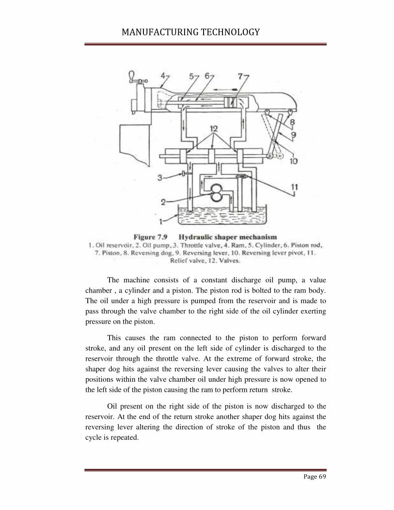
MANUFAC
The machine
chamber , a cylinder
The oil under a high
pass through the val
pressure on the pisto
This causes
stroke, and any oil
reservoir through th
shaper dog hits agai
positions within the
the left side of the pi
Oil present o
reservoir. At the end
reversing lever alter
cycle is repeated.
MANUFACTURING TECHNOLOGY
ine consists of a constant discharge oil pump
der and a piston. The piston rod is bolted to the r
igh pressure is pumped from the reservoir and is
alve chamber to the right side of the oil cylinde
ton.
s the ram connected to the piston to perform
il present on the left side of cylinder is discharg
the throttle valve. At the extreme of forward s
gainst the reversing lever causing the valves to a
e valve chamber oil under high pressure is now
piston causing the ram to perform return stroke.
on the right side of the piston is now discharg
nd of the return stroke another shaper dog hits a
tering the direction of stroke of the piston and
Page 69
p, a value
e ram body.
is made to
der exerting
rm forward
arged to the
stroke, the
o alter their
w opened to
arged to the
against the
d thus the

MANUFAC
The quick re
volume of the cylin
presence of piston r
fixed period, the sam
side of the cylinder.
This will me
smaller stroke volu
increasing the speed
Automatic cross fee
In a shaper b
or bevel surfaces ar
head by hand. Cros
surface. This is done
MANUFACTURING TECHNOLOGY
eturn motion is effected due to the difference
linder at both ends, the left hand being smaller d
rod. As the pump is a constant discharge one,
same amount of oil will be pumped into right or
ean that the some amount of oil will be packed
lume causing the oil pressure to rise automati
ed during the return stroke.
feed mechanism:-
r both down feed and cross feed can be obtained
are produced by rotating the down feed screw o
ross feed movement is used to machine a flat h
ne by rotating the cross feed screw by hand or po
Page 70
ce in stroke
r due to the
e, within a
or left hand
ed within a
atically and
ed. Vertical
of the tool
t horizontal
power.

MANUFACTURING TECHNOLOGY
Page 71
Rotation of the cross feed screw causes the table to move sideways at
the end of each return stroke to bring the uncut surface of the work. This is
done by automatic cross feed mechanism of shaper.
The rotation of the bull gear causes the driving disc to rotate in a
particular direction. The driving disc is T- slotted and position of the crank
attached to the connecting rod may be altered to give different throw of
eccentricity. The other end of the connecting rod is attached to the rocking
arm by a pin. The rocking arm is fulcrum at the centre of the ratchet wheel.
The ratchet wheel is keyed to the cross feed screw. The rocking arm houses
a spring loaded pawl which is straight on one side and bevel on the other
side..
As the driving disc rotates, the connecting rod starts reciprocating and
the rocking arm rocks on the fulcrum. When the driving disc rotates through
half of the revolution in the clockwise direction, top part of the rocking arm
moves in clockwise direction and the pawl being slant on one side slips over
the teeth of the ratchet wheel imparting it no movement.
As the driving disc rotates through the other half, the top of the
rocking arm now moves in the anticlockwise direction and the straight side
of the pawl engages with the teeth of the ratchet wheel causing the wheel to
move in anticlockwise direction only. As the driving disc is connected to the
bull gear the table feed movement is effected when the bull gear or driving
disc rotates through half of the revolution i.e, during return stroke only.
Rotation through other half imparts no feed movements. To reverse
the direction of rotation of ratchet wheel and feed, a knob on the top of the
pawl after removing the pin is rotated through 180°.
The movement of feed may be altered by shifting the position of
crank pin w.r.t the centre. Greater the through the eccentricity more will be
the rocking movements of the arm and the pawl will pass through three or
four teeth on the ratchet wheel at a time imparting greater feed movement.

MANUFACTURING TECHNOLOGY
Page 72
Planning Machine
Chapter-5
The planner like a shaper is a machine tool to produce plane and flat
surfaces by a single point cutting tool
Difference between shaper & planner
The work is stationary; the tool along with ram reciprocates against the
work.
The work which is supported on the table reciprocates and the tool is
stationary.
MANUFACTURING TECHNOLOGY
Page 73
Principal parts of a planner:
BED:
� The bed of a planner is a box like casting cross ribs.
� It is a very large in size and heavy in weight and it supports the
column and all other moving parts of the machine.
� The guides ways are provided on the bed for the movement of the
table.
� The hollow space within the box like structure of the bed home the
driving mechanism for the table.
Table:
� The table supports the job and reciprocates along the ways of the
bed.
� The planner table is heavy rectangular casting and is made of cast
iron.
� The top face of the table is accurately finished in order to hold the
job correctly.
� The top face of the table is ‘T’ slotted for clamping the job and job
holding devices.
� At each end of the table or hollow space is left for collecti9ng chips.
� A groove is cut on the side of the table for clamping planner revising
dugs at different position.

MANUFAC
Column:
� It is a rigid ve
� The front fac
guide ways o
accommodati
� The housing
screws for to
rail.
CROSS RAIL:
� It is a rigid bo
� The cross rail
and can be cl
� The cross rail
surface of the
MANUFACTURING TECHNOLOGY
vertical box like structure.
face of each housing is accurately machines to
on which the crosier may be slipped up and
ating the different suitable heights job.
g is enclosed with vertical elevating screw and c
tool heads and counter balanced the weight of
box like casting connecting the two housings.
ail can be raised or lowered on the face of the hou
clamped at any desired position.
ail when clamped showed remain parallel to the to
he table.
Page 74
to provide
d down for
cross feed
of the cross
ousing
top

MANUFACTURING TECHNOLOGY
Page 75
� The two elevating screws in two the housing are rotated by an equal
horizontal any in position.
� The two tool heads are mounted upon the cross rail.
� The cross rail has screws for vertical and cross flew of the tool heads
and a screw for elevating the rail.
TOOL HEAD:
� The tool head of the planer is similar to that of a shaper in
construction and operation.
CLAMPING OF JOB:
� There are three important points to be hosted while clamping the job
on the planer table.
� The work should be connected rigidly to the table so that it may not
be shifted out of its position while cutting progresses.
� Proper clamping should be done all round the job.
� The job should be so held that the surface planed should remain in
proper position with other surface.
� The job may be located on the planning machine table by the
following methods.
� By standard clamping devices.
� By special fixtures.
� The standard clamping devices are t-bolts, stops, planer jacks, heavy
duty vises, angle plates & planner centres etc.
PLANER TOOLS:
� The cutting tools which are uses in planer are single point cutting
tool which are used in lathe and shaper.
� Planer tools may be solid for get type or bit type.
� The bit may be brazed, welded or mechanically held on a m.s bar.
� As a planer tool has to take up heavy cuts, the tools are made fevaier
and larger in cross section.

MANUFACTURING TECHNOLOGY
Page 76
Milling Machine
Chapter-6
Milling machine:
A milling m/c is a type of metal cutting device which remove metal
with a fast rotating multi-touch cutter.
As this m/c yield high production of different varities of jobs, in
choice for production m/c, comes after the lathe.
Generally smaller jobs are employed for machining in milling m/c. If larger
jobs are handled, then the m/c will perhaps be slower.

MANUFACTURING TECHNOLOGY
Page 77
Because of using multi tooth cutters & various forms of cutters, a
milling m/c can be economically employed for generating varties of surfaces
quite speedily.
Types of milling m/c:
Milling m/c are available in various basing covering a wide range of
work & capacities. The choice for a particular m/c depends on the nature &
size of the work to be undertaken.
a) Column & knee type. Milling m/c.
a. Hand milling m/c
b. Plain milling m/c
c. Universal milling m/c
d. Omniversal milling m/c
e. Vertical milling m/c
b) Manufacturing/ fixed bed type. Milling m/c
c) planer type milling m/c
d) Special type milling m/c.
a. Rotary table machine.
b. Drum milling m/c.
Milling attachment:
It is a rotary table types work holding device bolted on the table. It
provides a rotary motion to the w/p in addition to longitudinal, cross &
vertical motions.
Dividing head/indexing head:
Indexing is an operation of dividing a periphery of a cylindrical w/p
into equal no. Of divisions by the help of index crank & index plate.
Indexing is accomplished by using a special attachment known as
dividing head/indexing head.
Dividing heads are 3 types
1. Plain/simple dividing head:
2. Universal dividing head
3. Optical dividing head.

MANUFAC
Plain/ simple dividi
� It has
three j
� A wor
crank
index
� In a
horizo
� The in
horizo
� The i
perform
MANUFACTURING TECHNOLOGY
iding head:
as a spindle which carries job holdering device
e jaw chuck, face plate with centre carrier
orm wheel is rigidly fixed on spindle. While an
k is mounted on the worn shaft such that the ro
x crank finally results in the rotation of the spindl
plane dividing head, its spindle rotates onl
zontal axis.
index plate remains fixed & does not rotates on
zontal axis.
index plate remains fixed & does not rota
orming simple indexing operation.
Page 78
ces such as
an indexing
rotation of
dle.
nly around
only around
otate while

MANUFACTURING TECHNOLOGY
Page 79
The amount of the spindle relative to the worm depends on the ratio
between the relations of worm & the worm wheel.
The most common ratio is 40:1, which means 40 revolutions of index
crank or worm will move the worm wheel or spindle through one complete
revolution.
Universal dividing head:
� It is the most commonly used type of attachment on the
milling m/c.
� It is used for the following purposes.
� Setting the w/p in horizontal, vertical & inclined positions
relative to the milling m/c table.
� Turning the work periodically through a given angle per
forming indexing of the work.
� Imparting a continuous rotary motion to the w/p for milling
helical grooves.
� Dividing head spindle is connected with the table feed screw
through a gear train attachment to impart a continuous rotary
motion to the w/p for helical milling.
� Working mechanism of an universal dividing head is the crank
which is rigidly fixed at one end of the work shaft, while the
bevel gear runs free on the worm shaft.
� The index plate is bolted with gear & can be locked aginst the
rotation of lock pin.
Optical dividing head:
It is used for high precision angular indexing of the job with respect to
the cutter.
For reading the angle, on optical system is built into the dividing
head.
Spindle:
Spindle is located in the upper part of the column.
It gets driving power from motor to transmit it to the arbor.
The front end of the spindle just projects from the column face & is
provided with a tapered hole to accommodate various cutting tools & arbors.

MANUFACTURING TECHNOLOGY
Page 80
Arbour:
The arbor is connected with a spindle through a bolt, which serves as
an extension of the m/c spindle on which milling cutters are safely mounted
& rotated
It is taper shank for proper alignment with the spindle having tapered
hole at its nose.
Work holding devices:
Work holding device used on a milling m/c includes the following:
Vices which may be plain vice, swivel vice & tool maker’s universal vice.
� Angle plates.
� v-blocks
� special fixtures.
Work holding attachment:
Special attachments are used on miiling m/c for performing different
typical operations. Common attachments include:
a. Vertical milling attachment: used for facilitating the horizontal spindle
milling m/c to do facing on horizontal surface or for making grooves.
b. Universal milling attachment: similar to vertical attachment with
added features for swivelling the spindle about two mutually
perpendicular axis.
slitting attachment :
used for converting rotational motion of the horizontal spindle m/c
into up & down vertical reciprocating motions. The slotting head is fitted to
the spindle & is used for cutting slats. The attachment can be swivelled to
any angular positions.
high speed milling attachment:
it is a gearing system used for increasing the spindle speed by four
to six times. The attachment is bolted to the face of the column.

MANUFACTURING TECHNOLOGY
Page 81
Rack milling attachment:
It is bolted to the face of the column. Used for cutting rake teeth.
Differential Indexing :
Available no. Of index plates with different hole circles sometimes
limit the range of plate indexing. In such case differential indexing is found
useful. In this process, the indexing plate rotates itself in relation to the crank
during the process of indexing. For making necessary calculation to find the
change gears to be placed between the spindle and the power shaft use the
following relation
Where N = no. Of divisions to be indexed
N is a no. Of slightly or less than N. After simplification, the above
relation n will give the gear ratio between the gears to be placed on the
spindle (driver) and the own shaft (driver).
Gears may be arranged in a simple train or in a compound train as the
case may be.
When (n – N) is positive, the index plate must rotate in the direction
in which the crank is rotated.
If (n – N) is negative the index plate rotates in the opposite direction
to that of the crank.
Dividing head attachment:
A dividing head attachment is also a special work holding de3cvice
which is bolted on the machine plate. The work may be mounted on a chuck
fitted on the dividing head spindle or may be supported between alive or
dead centre.
The dead centre is mounted on a foot stock as in a lathe tail stock that
is bolted on the machine table after after correctly aligning its spindle axis
with the dividing heads. spindle
MANUFACTURING TECHNOLOGY
Page 82
Universal dividing head:
The attachment is similar to the vertical attachment but it has an added
arrangement for swivelling the spindle about two mutually perpendicular
axes. This feature of the attachment permits the cutting spindle axis to swivel
at practically any angle and machine any compound angle surface of the
work. The attachment is supported by the over-ram and operates at either the
same speed or at higher speed than the scope of machine.
MANUFACTURING TECHNOLOGY
Page 83
Slotter
Chapter-7
SLOTTER
It is used for cutting grooves, key ways and slots of various shapes
for making regular and irregular surfaces both internal and external.
Difference between slotter and shaper:
SLOTTER SHAPER
The ram holds the tool and reciprocates in a vertical axis
The ram holds the tool and reciprocates in a horizontal axis.

MANUFACTU
SLOTTING MACH
Base/bed:
The base of th
forces and entire loa
NUFACTURING TECHNOLOGY
CHINE PARTS:
f the machine is rigidly built to withstand all cuttin
oad of the machine.
Page 84
ting

MANUFACTURING TECHNOLOGY
Page 85
COLUMN:
� The column is the vertical member which is cast integral with the
base.
� Driving mechanism and feeding mechanism are inside the column.
� The front vertical face of column is accurately finished for providing
ways on which the ram reciprocates.
SADDLE:
� The saddle is mounted upon the guideways and may be moved
towards or away from the column either by power/ manual control to
supply longitudinal feed to the work.
� The top surface of the saddle is accurately finished to provide
guide ways for the cross slide.
� These guideways are perpendicular to the guide ways on the base.
CROSS SLIDE:
� The cross slide is mounted upon the guide ways of the saddle and
may be moved parallel to the face of the column. The movement of
the slide may be controlled either by head or power to supply cross
feed.
ROTATING TABLE:
� The rotating table is a circular table which is mounted on the top of
the cross slide. The table may be rotated by rotating a worn which
meshes with a worm gear connected to the underside of the table.
� In same machines the table is graduated in degrees that enable the
table to be rotated for indexing.
� T-slots are cut on the top face of the table for holding the work by
different clamping devices.
� The rotary table enables a circular or contoured surface to be
generated on the work piece.
RAM & TOOTHED ASSEMBLY:
� The ram is the reciprocating member of the machine mounted on the
guide ways of the column.
� It supports the tool at it’s bottomed on tool head.
MANUFACTURING TECHNOLOGY
Page 86
RAM DRIVE MECHANISM:
� A slotter removes metal during downward cutting stroke only whereas
during upward return stroke no metal is removed.
� To reduce the idler time quick return mechanism is incorporated in
the machine.
FEED MACHANISM:
� The teed is given by the table.
� A slotting machine table has 3 types of feed movements.
LONGITUDINAL:
� If the table is fed perpendicular to the column towards or away from
face the feed movement is termed as longitudinal.
CROSS: If the table is feed parallel to the face of the column the feed
movement is termed as cross.
CIRCULAR: If the table is rotated on a vertical axis the feed movement is
circular.
SLOTTER TOOLS:
� = top rake angle
� = from clearance angle
� In a slotter the pr. Acts along the length of the tool.
� In slotter tool the angles are provided for better cutting.
� The nose of the tool projects slightly beyond the shank to provide
clearance.
� The slotter tools are robust in cross section and usually of torged
type.
� Bit type tools are fitted in heavy duty tool holders.
� Key way cutting tools are thinner at the cutting edges.
� Round nose tools are used for machining circular/ contoured
surfaces.
� Square nosed tools are used for machining flat surfaces.

MANUFACTURING TECHNOLOGY
Page 87
Grinding
Chapter-8
Grinding M/C:
• Grinding is the process of removing material from work piece. The
removing of material from the W/P is either two end its diametre
within very closed tolerance (0.02mm) or to give a fine finish or the
work surface.
• The grinding machine supports and rotates the grinding wheel for
smooth operation. Grinding machine is used for roughing and
finishing flat, cylindrical and conical surface.
MANUFACTURING TECHNOLOGY
Page 88
• The grinding wheel is made of fine grains of abrasive materials. The
grains during the rotation of the wheels remove very small chip[s .
• As the selection of chips remove is very small and high cutting speed
are involved, the grinding operation results into a very good finish or
the work surface and high accuracy in work dimensions.
Types of Grinding:
Oftainly used to grind casting and weldments using portable grinders
or pedestal; grinder
Fine Grinding :
• It is applied for finishing of those materials which are too hard to be
machined by other methods of metal cutting.
• It is also used for producing surface on the job to attain higher
dimensional accuracy and finish
BED/BASE
• It is a heavy cast iron construction and support s other parts of the
slotting machine such as column, ram and its driving mechanism,
table etc.
• The top of the base is accurately finished to provide guide ways for
mounting of the saddle. The cross-slide guide ways are
perpendicular to the column face.
Column
• It is a vertical structure cast integral with the base.
• It houses the mechanism for driving ram and feeding mechanism.
• The front vertical face of the column carries guide ways for ram
to reciprocating upon it
Saddle:
• It is mounted upon guide ways and can be moved towards or away
from the column
• The saddle caries guide ways for cross-slide
• The feed is given by manual or power.

MANUFACTURING TECHNOLOGY
Page 89
Cross-slide:
• It is mounted upon guide ways made at the top of the saddle and
can be moved parallel to the front face of the column.
• Feed is given manual or by power.
• Table
• It is a circular rotary table mounted on the top of the cross-slide
• A circular feed handle for the table is provided
• Rotation of the table is effected by hand or by power
• The table carries T-slots to help mounting of jobs on the tabloe
• Ram and tool head
• They reciprocates up and down on the guide ways made on the front
face on the column.
• The ram carries a tool head at its bottom end.
• In some mechanism special tool head is provided to releave the tool
during its return stroke
• A quick return mechanism is given with the machine which enables
the return or ideal stroke to be completed faster than the cutting
stroke
Methods of grinding:
According to type surface to be grounded main kinds of grinding
methods are as follow:
External cylindrical grinding: produces a straight or tappered surface
on a w/p when it is rotated about its own axis between centers as it passes
lengthwise across the face of a revolving grinding wheel.
Internal cylindrical grinding: it produces internal cylindrical holes &
tapers. The work is chucked & rotated on its axis, while the grinding wheel
rotates against the work.
Surface grinding:
It produces flat surfaces & the work may be grounded either by
periphery or by end face of the grinding wheel.
MANUFACTURING TECHNOLOGY
Page 90
Face grinding:
It is a method of grinding vertical flat surface & the wheel spindle
may be vertical or horizontal.
From grinding:
It is done by specially shaped grinding wheels to grind formed
surfaces as gear teeth, threads, shaft, dovetails etc.
Set wheel grinding:
It is a method of grinding short w/p without changing the grinding
wheel.
Centre less grinding:
It is a method of grinding external & internal cylindrical surfaces in
which the work is supported among a regulating wheel, a grinding wheel &
a work rest blade.
Off-hand grinding:
It is rough grinding method in which work is held in hand and
pressed
Against the rotating grinding wheel. For example grinding a chisel
on pedestal grinder

MANUFACTURING TECHNOLOGY
Page 91
Types of grinding machine:
Grinding machine may be broadly classified as follows
1. Surface grinder
2. Cylindeical grinder
3. Center-less grinder
4. Portable grinder
5. Pedestal grinder
6. Cutter and tool grinder
7. Internal grinder
8. Flexible shaft grinder
Surface grinder :
a. It is used for grinding flat surfaces
b. Surface grinding effective for removing hard spots and sets
from the work surface
c. Surface grinding machine differs according the shape of
grinding wheel and motion given to the work table during
working.
d. Some common type surface grinding machine are prescribed
in the following
Horizontal spindle surface grinding machine:
It is used for the circumferemce of a straight grinding wheel and are
able to handle a wide range of work with super finish and externally fine
limits of accuracy
Vertical spindle flat grinding machine:
These are strongly built machine. They yield more out put with cup
type wheel rather than using of straight wheels.
Disc grinding machine:
These are used for rough semi precision grinding rapid removal of
metal is done by this type of machine.

MANUFACTURING TECHNOLOGY
Page 92
Internal Machining operations
Chapter-9
MANU
Introduction
MANUFACTURING TECHNOLOGY
Page 93

MANU
MANUFACTURING TECHNOLOGY
Page 94

MANU
MANUFACTURING TECHNOLOGY
Page 95

MANU
MANUFACTURING TECHNOLOGY
Page 96
MANUFACTURING TECHNOLOGY
Page 97

MANU
MANUFACTURING TECHNOLOGY
Page 98

MANU
MANUFACTURING TECHNOLOGY
Page 99

MANU
MANUFACTURING TECHNOLOGY
Page 100

MANU
MANUFACTURING TECHNOLOGY
Page 101

MANU
MANUFACTURING TECHNOLOGY
Page 102

MANU
MANUFACTURING TECHNOLOGY
Page 103

MANU
MANUFACTURING TECHNOLOGY
Page 104

MANU
MANUFACTURING TECHNOLOGY
Page 105

MANUFACTURING TECHNOLOGY
Page 106
Surface finish, lapping
Chapter-10
Introduction:
In a manufacturing plant, a product may be shaped, turned,
milled or drilled, and left in that condition as being satisfactory for use.
However, if a better finish is desired, for looks, for accuracy, for
wearing qualities, or for any other reasons, one of the micro finished
that include lapping, honing, super finishing, polishing, buffing, may
be employed. In some cases other operations are done only to get
durable finishes.

MANUFACTURING TECHNOLOGY
Page 107
LAPPING:
Lapping is an abrading process that is used to produce
geometrically true surfaces, correct minor surface imperfection,
improve dimensional accuracy, or provide a very close fit between two
contact surfaces. Very thin layers of metal (0.005 to 0.01mm)are
removed in lapping and it is therefore, evident that is unable to correct
substantial error in the form and size of surface, it is however low
efficiency process is used only when specified accuracy and surface
finish cannot be obtained by other method. Abrasive powders (floors
such as emery, corundum iron oxide, chromium oxide mixed with oil is
mixed with oil or special paste with some carrier are used in lapping.
Most lapping is done by means of lapping shoes or quills called
laps that are robbed against the work. The face of a lap becomes
‘charged’ with abrasive particle. Charging a lap means to embed the
abrasive grains into surface. Laps may be made of almost of any
material soft enough to receive and retain the abrasive grains. They are
made of soft iron, brass, copper, lead or soft steel.
The method of charging a lap depends upon the shape of lap.
When the lap is once charged it should be used without applying more
abrasive until it ceases to cut. Lap may be operated by hand or
machine, the motion being rotary or reciprocating.
Cylindrical work may be lapped by rotating the work in the lathe
or drill press and reciprocating the lap over the work in an ever-
changing path. Small flat surfaces may be lapped by holding the work
against a rotating disc, or the work may be moved by hand in an

MANUFACTURING TECHNOLOGY
Page 108
Irregular path over a stationary face plate lap. In equalizing lapping the
work and lap mutually improve each other surfaces as they slide on
each other.
There are three important types of lapping machines. The
vertical axis lapping machine laps flat or round surfaces between two
oppose laps on vertical spindle. The centre-less lapping machine is
designed for continuous production of round parts such as piston pins,
bearing races and cups, valve tappets and shafts.
The centre less lapping machine on the same principle as centre
less grinding. The abrasive belt lapping machine lapps bearings and
cam surfaces by means of abrasive coated clothes.