lessons learnt from egress drift excavation through a ...€¦ · undercutting method to induce...
TRANSCRIPT
Underground Mining Technology 2017 – M Hudyma & Y Potvin (eds) © 2017 Australian Centre for Geomechanics, Perth, ISBN 978-0-9924810-7-0
Underground Mining Technology 2017, Sudbury, Canada 645
Lessons learnt from egress drift excavation through a minor pillar in an extraction level, Deep Ore Zone mine, Freeport Indonesia, Papua
SA Firmanulhaq PT Freeport Indonesia, Indonesia
J Kamarea PT Freeport Indonesia, Indonesia
R Hasan PT Freeport Indonesia, Indonesia
F Putra PT Freeport Indonesia, Indonesia
F Salim PT Freeport Indonesia, Indonesia
Abstract The Deep Ore Zone (DOZ) mine is one of Freeport Indonesia’s block cave mines with maximum production of 40,000 tpd (2016) from 650 active drawpoints. Damage leading to ground collapse was well understood as one of the major factors causing production interruption. Ground collapses had different characteristics and severity, so challenges and objectives of the rehab works are varied.
Rehabilitation of ground collapse is not only performed to achieve production targets, but is also related to ventilation, access, and cost. Causes of collapse of the 90 m long panel 02 drawpoint 17 to 21 west were identified as a combination of geological features (structure), load static, and ground support resistance. Due to the collapsed area being surrounded by very wet and fine materials from the drawpoint (mud rush potential), and considering previous rehabilitation rate performance, excavation of an egress drift (only for man access) through a minor pillar from panel 02 to panel 01 was the decided as a reasonable alternative.
The excavation of the egress drift through unidentified pillar conditions and below load static cave material requires more investigation to achieve a suitable project outcome. Borehole camera survey and numerical modelling helped geotechnical engineers to identify the hazards in terms of drift stability and support system. This paper presents the lesson learnt during the assessment and excavation works.
Keywords: collapsed drift, minor pillar, egress drift, block cave, safety, modelling
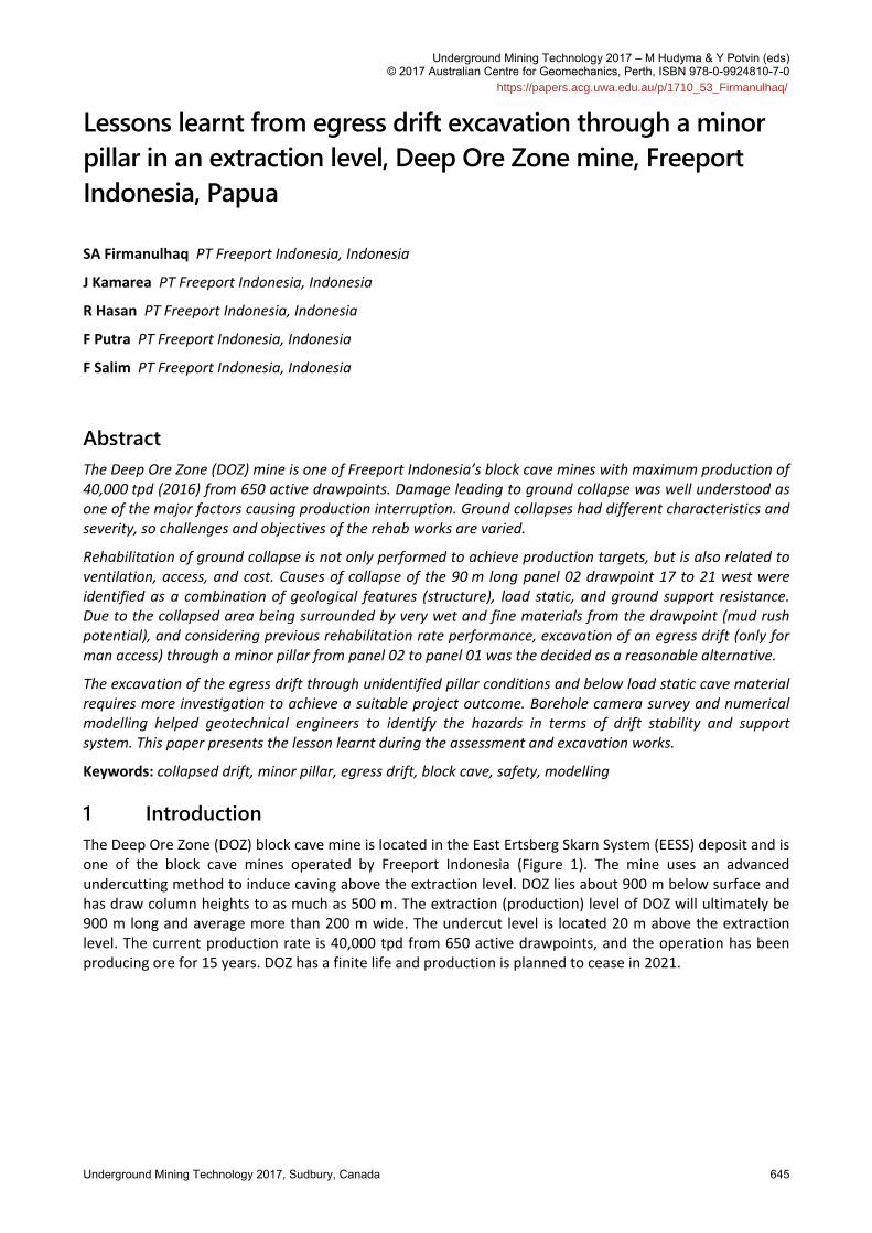
1 Introduction The Deep Ore Zone (DOZ) block cave mine is located in the East Ertsberg Skarn System (EESS) deposit and is one of the block cave mines operated by Freeport Indonesia (Figure 1). The mine uses an advanced undercutting method to induce caving above the extraction level. DOZ lies about 900 m below surface and has draw column heights to as much as 500 m. The extraction (production) level of DOZ will ultimately be 900 m long and average more than 200 m wide. The undercut level is located 20 m above the extraction level. The current production rate is 40,000 tpd from 650 active drawpoints, and the operation has been producing ore for 15 years. DOZ has a finite life and production is planned to cease in 2021.
https://papers.acg.uwa.edu.au/p/1710_53_Firmanulhaq/
Lessons learnt from egress drift excavation through a minor pillar in an extraction level, SA Firmanulhaq et al. Deep Ore Zone mine, Freeport Indonesia, Papua
646 Underground Mining Technology 2017, Sudbury, Canada
Figure 1 Location of PT Freeport Indonesia mining operation
Block caving is a continuous mining concept; ore is producing constantly using manual load–haul–dump units (LHDs) and remotely operated LHD (operated remotely). A remote LHD system is used when for one of the drawpoints in one panel, the material class is changed into red class (wet and fine grain material). Ore in panel 02 is fully producing using a remote loader system, while in the middle of the panel, there was a blockage with collapse material at drawpoint 17 to 21 west (90 m long). A secondary egress drift was designed for man access in the event of spill out/mud rush.
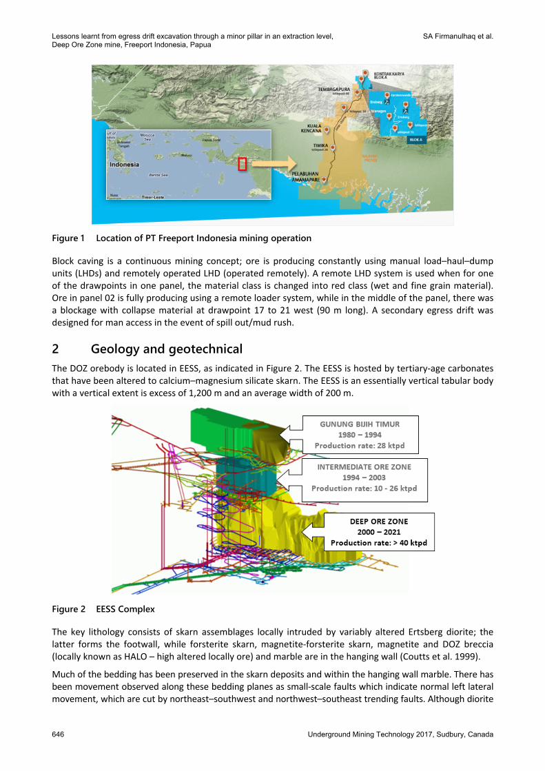
2 Geology and geotechnical The DOZ orebody is located in EESS, as indicated in Figure 2. The EESS is hosted by tertiary‐age carbonates that have been altered to calcium–magnesium silicate skarn. The EESS is an essentially vertical tabular body with a vertical extent is excess of 1,200 m and an average width of 200 m.
Figure 2 EESS Complex
The key lithology consists of skarn assemblages locally intruded by variably altered Ertsberg diorite; the latter forms the footwall, while forsterite skarn, magnetite‐forsterite skarn, magnetite and DOZ breccia (locally known as HALO – high altered locally ore) and marble are in the hanging wall (Coutts et al. 1999).
Much of the bedding has been preserved in the skarn deposits and within the hanging wall marble. There has been movement observed along these bedding planes as small‐scale faults which indicate normal left lateral movement, which are cut by northeast–southwest and northwest–southeast trending faults. Although diorite
Poster papers
Underground Mining Technology 2017, Sudbury, Canada 647
has healed most structures, there are prominent joint sets cutting the diorite and skarn, with as many as four sets observed. Ground conditions within the EESS system are highly variable. Within zones of good to very good ground conditions there are elongated zones of very poor ground conditions characterised by low strength, low core recovery and low rock quality designation (RQD) values. The values of the uniaxial compressive strength (UCS), RQD, and rock mass rating (RMR) classifications are indicated in Table 1.
Table 1 Geotechnical classification and its distribution in the DOZ (Widijanto 2006)
Rock type UCS (MPa) RQD (%) RMR class Percentage (%)
DOZ breccia 22.3 40 Very poor 9.57
Marble‐sandstone 22.3 65 Poor 1.20
Forsterite skarn 127.3 84 Good 20.6
Fors‐mag skarn 56.9 67 Fair 16.3
Magnetite skarn 97.5 71 Good 1.9
Diorite 111 80 Good 49.9
Other 0.52
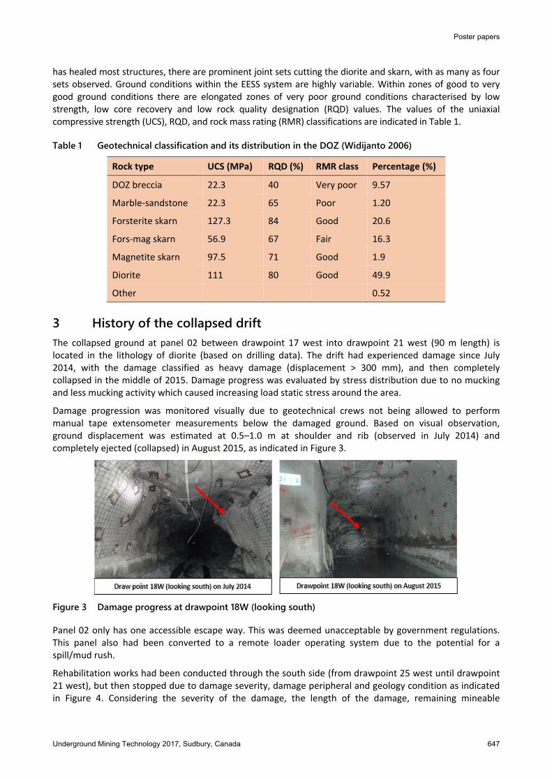
3 History of the collapsed drift The collapsed ground at panel 02 between drawpoint 17 west into drawpoint 21 west (90 m length) is located in the lithology of diorite (based on drilling data). The drift had experienced damage since July 2014, with the damage classified as heavy damage (displacement > 300 mm), and then completely collapsed in the middle of 2015. Damage progress was evaluated by stress distribution due to no mucking and less mucking activity which caused increasing load static stress around the area.
Damage progression was monitored visually due to geotechnical crews not being allowed to perform manual tape extensometer measurements below the damaged ground. Based on visual observation, ground displacement was estimated at 0.5–1.0 m at shoulder and rib (observed in July 2014) and completely ejected (collapsed) in August 2015, as indicated in Figure 3.
Figure 3 Damage progress at drawpoint 18W (looking south)
Panel 02 only has one accessible escape way. This was deemed unacceptable by government regulations. This panel also had been converted to a remote loader operating system due to the potential for a spill/mud rush.
Rehabilitation works had been conducted through the south side (from drawpoint 25 west until drawpoint 21 west), but then stopped due to damage severity, damage peripheral and geology condition as indicated in Figure 4. Considering the severity of the damage, the length of the damage, remaining mineable
Lessons learnt from egress drift excavation through a minor pillar in an extraction level, SA Firmanulhaq et al. Deep Ore Zone mine, Freeport Indonesia, Papua
648 Underground Mining Technology 2017, Sudbury, Canada
reserves, liabilities due to government regulations, rehabilitation rates, cost, and the panel being situated at a potential wet muck spill/mud rush location, excavation of a secondary egress through a minor pillar of panel 02 to 01 has been decided as a reasonable alternative.
Figure 4 Peripheral of damage overlaid with geological condition
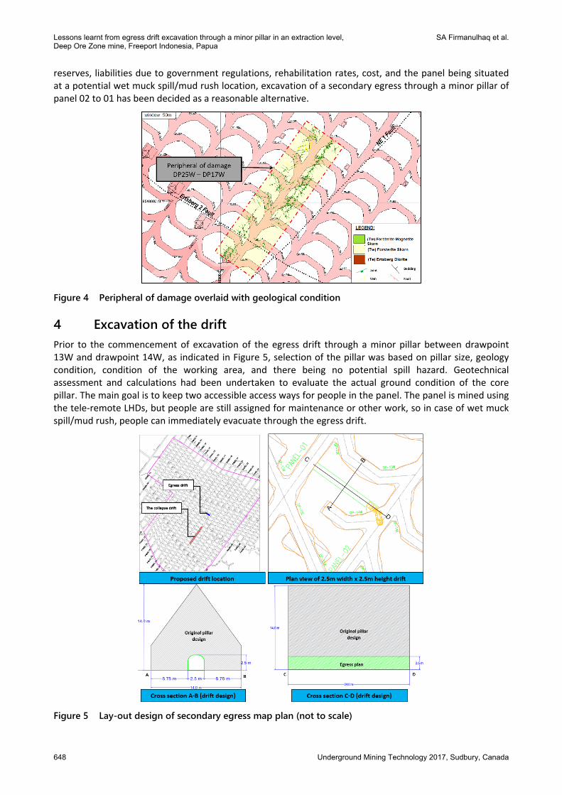
4 Excavation of the drift Prior to the commencement of excavation of the egress drift through a minor pillar between drawpoint 13W and drawpoint 14W, as indicated in Figure 5, selection of the pillar was based on pillar size, geology condition, condition of the working area, and there being no potential spill hazard. Geotechnical assessment and calculations had been undertaken to evaluate the actual ground condition of the core pillar. The main goal is to keep two accessible access ways for people in the panel. The panel is mined using the tele‐remote LHDs, but people are still assigned for maintenance or other work, so in case of wet muck spill/mud rush, people can immediately evacuate through the egress drift.
Figure 5 Lay-out design of secondary egress map plan (not to scale)
Poster papers
Underground Mining Technology 2017, Sudbury, Canada 649
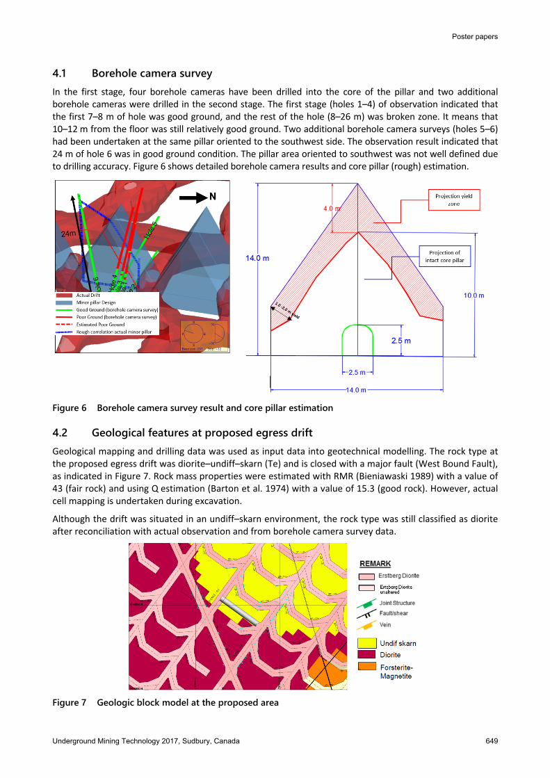
4.1 Borehole camera survey In the first stage, four borehole cameras have been drilled into the core of the pillar and two additional borehole cameras were drilled in the second stage. The first stage (holes 1–4) of observation indicated that the first 7–8 m of hole was good ground, and the rest of the hole (8–26 m) was broken zone. It means that 10–12 m from the floor was still relatively good ground. Two additional borehole camera surveys (holes 5–6) had been undertaken at the same pillar oriented to the southwest side. The observation result indicated that 24 m of hole 6 was in good ground condition. The pillar area oriented to southwest was not well defined due to drilling accuracy. Figure 6 shows detailed borehole camera results and core pillar (rough) estimation.
Figure 6 Borehole camera survey result and core pillar estimation
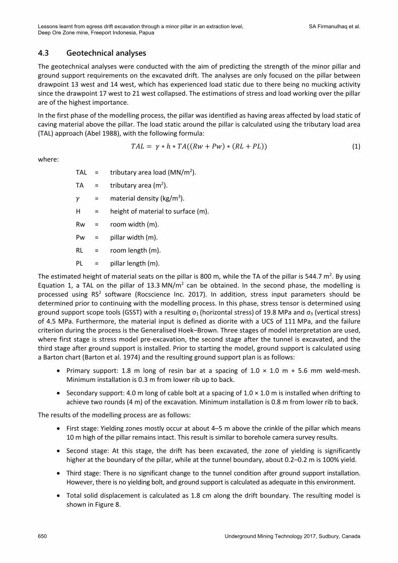
4.2 Geological features at proposed egress drift Geological mapping and drilling data was used as input data into geotechnical modelling. The rock type at the proposed egress drift was diorite–undiff–skarn (Te) and is closed with a major fault (West Bound Fault), as indicated in Figure 7. Rock mass properties were estimated with RMR (Bieniawaski 1989) with a value of 43 (fair rock) and using Q estimation (Barton et al. 1974) with a value of 15.3 (good rock). However, actual cell mapping is undertaken during excavation.
Although the drift was situated in an undiff–skarn environment, the rock type was still classified as diorite after reconciliation with actual observation and from borehole camera survey data.
Figure 7 Geologic block model at the proposed area
Lessons learnt from egress drift excavation through a minor pillar in an extraction level, SA Firmanulhaq et al. Deep Ore Zone mine, Freeport Indonesia, Papua
650 Underground Mining Technology 2017, Sudbury, Canada
4.3 Geotechnical analyses The geotechnical analyses were conducted with the aim of predicting the strength of the minor pillar and ground support requirements on the excavated drift. The analyses are only focused on the pillar between drawpoint 13 west and 14 west, which has experienced load static due to there being no mucking activity since the drawpoint 17 west to 21 west collapsed. The estimations of stress and load working over the pillar are of the highest importance.
In the first phase of the modelling process, the pillar was identified as having areas affected by load static of caving material above the pillar. The load static around the pillar is calculated using the tributary load area (TAL) approach (Abel 1988), with the following formula:
∗ ∗ ∗ (1)
where:
TAL = tributary area load (MN/m2).
TA = tributary area (m2).
= material density (kg/m3).
H = height of material to surface (m).
Rw = room width (m).
Pw = pillar width (m).
RL = room length (m).
PL = pillar length (m).
The estimated height of material seats on the pillar is 800 m, while the TA of the pillar is 544.7 m2. By using Equation 1, a TAL on the pillar of 13.3 MN/m2 can be obtained. In the second phase, the modelling is processed using RS2 software (Rocscience Inc. 2017). In addition, stress input parameters should be determined prior to continuing with the modelling process. In this phase, stress tensor is determined using ground support scope tools (GSST) with a resulting σ1 (horizontal stress) of 19.8 MPa and σ3 (vertical stress) of 4.5 MPa. Furthermore, the material input is defined as diorite with a UCS of 111 MPa, and the failure criterion during the process is the Generalised Hoek–Brown. Three stages of model interpretation are used, where first stage is stress model pre‐excavation, the second stage after the tunnel is excavated, and the third stage after ground support is installed. Prior to starting the model, ground support is calculated using a Barton chart (Barton et al. 1974) and the resulting ground support plan is as follows:
Primary support: 1.8 m long of resin bar at a spacing of 1.0 × 1.0 m + 5.6 mm weld‐mesh. Minimum installation is 0.3 m from lower rib up to back.
Secondary support: 4.0 m long of cable bolt at a spacing of 1.0 × 1.0 m is installed when drifting to achieve two rounds (4 m) of the excavation. Minimum installation is 0.8 m from lower rib to back.
The results of the modelling process are as follows:
First stage: Yielding zones mostly occur at about 4–5 m above the crinkle of the pillar which means 10 m high of the pillar remains intact. This result is similar to borehole camera survey results.
Second stage: At this stage, the drift has been excavated, the zone of yielding is significantly higher at the boundary of the pillar, while at the tunnel boundary, about 0.2–0.2 m is 100% yield.
Third stage: There is no significant change to the tunnel condition after ground support installation. However, there is no yielding bolt, and ground support is calculated as adequate in this environment.
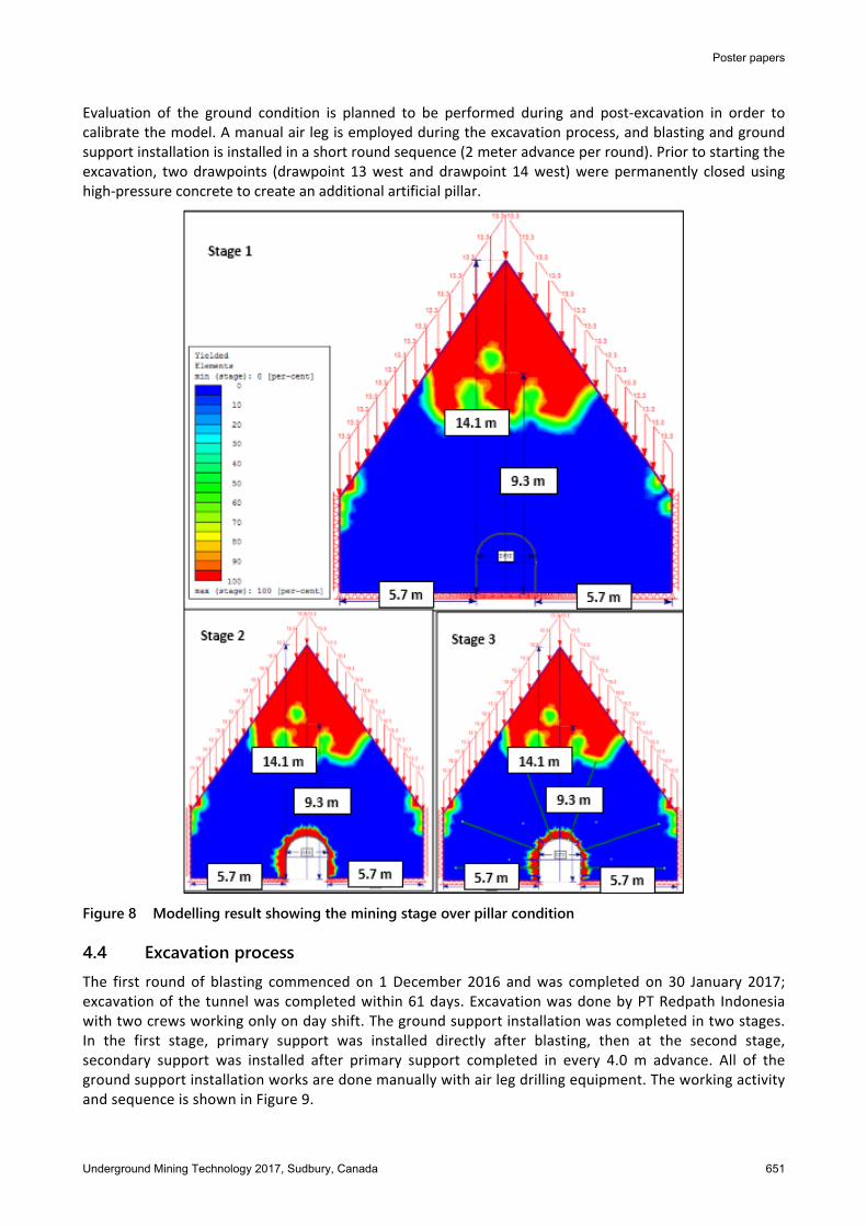
Total solid displacement is calculated as 1.8 cm along the drift boundary. The resulting model is shown in Figure 8.
Poster papers
Underground Mining Technology 2017, Sudbury, Canada 651
Evaluation of the ground condition is planned to be performed during and post‐excavation in order to calibrate the model. A manual air leg is employed during the excavation process, and blasting and ground support installation is installed in a short round sequence (2 meter advance per round). Prior to starting the excavation, two drawpoints (drawpoint 13 west and drawpoint 14 west) were permanently closed using high‐pressure concrete to create an additional artificial pillar.
Figure 8 Modelling result showing the mining stage over pillar condition
4.4 Excavation process The first round of blasting commenced on 1 December 2016 and was completed on 30 January 2017; excavation of the tunnel was completed within 61 days. Excavation was done by PT Redpath Indonesia with two crews working only on day shift. The ground support installation was completed in two stages. In the first stage, primary support was installed directly after blasting, then at the second stage, secondary support was installed after primary support completed in every 4.0 m advance. All of the ground support installation works are done manually with air leg drilling equipment. The working activity and sequence is shown in Figure 9.

Lessons learnt from egress drift excavation through a minor pillar in an extraction level, SA Firmanulhaq et al. Deep Ore Zone mine, Freeport Indonesia, Papua
652 Underground Mining Technology 2017, Sudbury, Canada
Figure 9 Working activity and sequence
5 Monitoring and evaluation post-excavation The main goal of this monitoring process is to monitor stability of the ground along the egress drift in which the results can be reconciled with geotechnical model. Two types of monitoring have been conducted – they are tape extensometer and ground penetrating radar (GPR).
5.1 Tape extensometer monitoring (convergence) Tape extensometers are designed to monitor ground deformation/displacement (Rachmad & Widijanto 2000), 1 m of convergence station is installed inside rib of the tunnel oriented horizontally at five locations along the tunnel. Convergence measurement is scheduled to be conducted on a weekly basis, but due to operational reasons, it is measured when panel 02 is opened. An initial measurement was undertaken on 22 February 2017, and the latest measurement was undertaken on 4 April 2017. The highest deformation is observed at stations number 1 and 5 (Figure 10) with a cumulative value of 6.0 mm. Both stations are located at the portal of the tunnel.
Figure 10 Convergence monitoring result
5.2 Ground penetrating radar survey GPR was used at the egress drift to survey the estimated ground condition in the minor pillar, especially on the back/roof side.
GPR is a geophysical method for high‐resolution detection, imaging and mapping of subsurface soils and rock conditions (Basson 2000). This non‐destructive method uses electromagnetic waves and detects the reflected signals from subsurface material. The GPR system has three main components: transmitter, receiver and a control/main unit. The transmitting antenna radiates a short, high‐frequency electromagnetic pulse into the
Poster papers
Underground Mining Technology 2017, Sudbury, Canada 653
ground, were it is refracted, diffracted and reflected as it encounters changes in dielectric permittivity and electric conductivity.
The propagation of a radar signal depends mainly on the electrical properties of the subsurface material. Waves that are scattered back towards the earth’s surface induce a signal in the receiving antenna and are recorded as digitised signals for display and further analysis.
The use of a borehole camera survey into the GPR survey line was conducted to increase the reliability of the GPR survey result due to there being no specific calibration data as comparison between wave reflection values from various rock types.
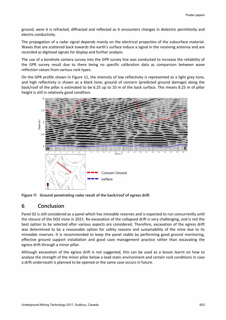
On the GPR profile shown in Figure 11, the intensity of low reflectivity is represented as a light grey tone, and high reflectivity is shown as a black tone, ground of concern (predicted ground damage) along the back/roof of the pillar is estimated to be 6.25 up to 10 m of the back surface. This means 8.25 m of pillar height is still in relatively good condition.
Figure 11 Ground penetrating radar result of the back/roof of egress drift
6 Conclusion Panel 02 is still considered as a panel which has mineable reserves and is expected to run concurrently until the closure of the DOZ mine in 2021. Re‐excavation of the collapsed drift is very challenging, and is not the best option to be selected after various aspects are considered. Therefore, excavation of the egress drift was determined to be a reasonable option for safety reasons and sustainability of the mine due to its mineable reserves. It is recommended to keep the panel stable by performing good ground monitoring, effective ground support installation and good cave management practice rather than excavating the egress drift through a minor pillar.
Although excavation of the egress drift is not suggested, this can be used as a lesson learnt on how to analyse the strength of the minor pillar below a load static environment and certain rock conditions in case a drift underneath is planned to be opened or the same case occurs in future.
Lessons learnt from egress drift excavation through a minor pillar in an extraction level, SA Firmanulhaq et al. Deep Ore Zone mine, Freeport Indonesia, Papua
654 Underground Mining Technology 2017, Sudbury, Canada
Acknowledgement The authors express their great appreciation to the management of PT Freeport Indonesia for their support and assistance, and for allowing this paper to be published. The authors also extend their thanks to their colleagues in the Geo Engineering Division at PT Freeport Indonesia for their assistance.
References Abel, JF 1988, ‘Soft rock pillars’, International Journal of Mining and Geological Engineering, vol. 6, no. 3, pp. 215–248. Barton, N, Lien, R & Lunde, J 1974, ‘Engineering classification of rock masses for the design of tunnel support’, Rock Mechanics,
vol. 6, no. 4, pp. 189–236. Basson, U 2000, Imaging of Active Fault Zone in the Dead Sea Rift: Evrona Fault Zone as a Case Study, PhD dissertation, Tel Aviv
University, Tel Aviv. Bieniawaski, Z 1989, Engineering Rock Mass Classification: A Complete Manual for Engineers and Geologist in Mining, Civil and
Petroleum Engineering, John Willey & Sons, New York. Coutts, BP, Susanto, H, Belluz, N, Flint, D & Edwards, A 1999, ‘Geology of the Deep Ore Zone, Ertsberg East Skarn System, Irian Jaya’,
Proceedings of the International Congress on Earth Science, Exploration and Mining Around the Pacific Rim: PACRIM ’99, The Australasian Institute of Mining and Metallurgy, Melbourne, pp. 539–547.
Rachmad, L & Widijanto, E 2000, ‘Application of convergence monitoring at PT Freeport Indonesia Deep Ore Zone Mine’, in R Hammah, W Bawden, J Curran & M Telesnicki (eds), Proceedings of the 5th North American Rock Mechanics Symposium and 17th Tunneling Association of Canada Conference, University of Toronto Press, Toronto, pp. 181–188.
Rocscience Inc. 2017, RS2, version 9.0, Rocscience Inc., Toronto, viewed 14 July 2017, https://www.rocscience.com/rocscience/ products/rs2
Widijanto, E 2006, ‘Geotechnical challenges in the DOZ block cave mine’, in CF Leung & YX Zhou (eds), Proceedings of the 4th Asian Rock Mechanics Symposium: Rock Mechanic in Underground Construction, World Scientific Publishing Co. Pte. Ltd., Singapore, pp. 210–216.