linear axis dge-zr/-sp - festo usa€¦ · linear axis dge-zr/-sp. dge-zr/-sp 2 festo –...
TRANSCRIPT

en Operating
instructions
8075157
2017-07g
[8075159]
Linear axis
DGE-ZR/-SP

DGE-ZR/-SP
2 Festo – DGE-ZR/-SP – 2017-07g
Original instructions
DGE-ZR-SP-EN
Identification of hazards and instructions on how to prevent them:
Danger
Immediate dangers which can lead to death or serious injuries
Warning
Hazards that can cause death or serious injuries
Caution
Hazards that can cause minor injuries
Other symbols:
Note
Material damage or loss of function
Recommendations, tips, references to other documentation
Essential or useful accessories
Information on environmentally sound usage
Text designations:
� Activities that may be carried out in any order
1. Activities that should be carried out in the order stated
– General lists
� Result of an action/References to more detailed information

DGE-ZR/-SP
Festo – DGE-ZR/-SP – 2017-07g English 3
1 Control sections and connections 4. . . . . . . . . . . . . . . . . . . . . . . . . . . . . . . . . . . . . . . . . . . .
2 Function and application 6. . . . . . . . . . . . . . . . . . . . . . . . . . . . . . . . . . . . . . . . . . . . . . . . . . .
3 Transport and storage 7. . . . . . . . . . . . . . . . . . . . . . . . . . . . . . . . . . . . . . . . . . . . . . . . . . . . .
4 Requirements for product use 7. . . . . . . . . . . . . . . . . . . . . . . . . . . . . . . . . . . . . . . . . . . . . . .
5 Installation 8. . . . . . . . . . . . . . . . . . . . . . . . . . . . . . . . . . . . . . . . . . . . . . . . . . . . . . . . . . . . . .
Mechanical installation 8. . . . . . . . . . . . . . . . . . . . . . . . . . . . . . . . . . . . . . . . . . . . . . . . . . . . . . . . . .
Installing the effective load 13. . . . . . . . . . . . . . . . . . . . . . . . . . . . . . . . . . . . . . . . . . . . . . . . . . . . . . .
Installing external accessories 15. . . . . . . . . . . . . . . . . . . . . . . . . . . . . . . . . . . . . . . . . . . . . . . . . . . . .
Electrical installation 21. . . . . . . . . . . . . . . . . . . . . . . . . . . . . . . . . . . . . . . . . . . . . . . . . . . . . . . . . . . .
Installing circuitry 21. . . . . . . . . . . . . . . . . . . . . . . . . . . . . . . . . . . . . . . . . . . . . . . . . . . . . . . . . . . . . . .
6 Commissioning 22. . . . . . . . . . . . . . . . . . . . . . . . . . . . . . . . . . . . . . . . . . . . . . . . . . . . . . . . . . .
Preparing for commissioning 22. . . . . . . . . . . . . . . . . . . . . . . . . . . . . . . . . . . . . . . . . . . . . . . . . . . . . .
Carrying out commissioning 26. . . . . . . . . . . . . . . . . . . . . . . . . . . . . . . . . . . . . . . . . . . . . . . . . . . . . . .
7 Operation 27. . . . . . . . . . . . . . . . . . . . . . . . . . . . . . . . . . . . . . . . . . . . . . . . . . . . . . . . . . . . . . .
8 Service and maintenance 28. . . . . . . . . . . . . . . . . . . . . . . . . . . . . . . . . . . . . . . . . . . . . . . . . . .
9 Repair 31. . . . . . . . . . . . . . . . . . . . . . . . . . . . . . . . . . . . . . . . . . . . . . . . . . . . . . . . . . . . . . . . . .
10 Accessories 31. . . . . . . . . . . . . . . . . . . . . . . . . . . . . . . . . . . . . . . . . . . . . . . . . . . . . . . . . . . . . .
11 Eliminating malfunctions 32. . . . . . . . . . . . . . . . . . . . . . . . . . . . . . . . . . . . . . . . . . . . . . . . . . .
12 Technical specifications (not valid for DGE-...-RF) 34. . . . . . . . . . . . . . . . . . . . . . . . . . . . . . .

DGE-ZR/-SP
4 Festo – DGE-ZR/-SP – 2017-07g English
1 Control sections and connections
For all available product documentation � www.festo.com/pk
1
2
3
4567
8
9
aJ
aA aB aC aD
1
aEToothed belt types
DGE-...-ZR
aG
aF
Fig. 1
1 Drive shaft (with one, two or no shaftextension(s), depending on order)
2 Corner profile for mounting of centralsupports (with DGE-8 ... 25)
3 Hole in the driver for mounting the effectiveload (only with DGE without guide)
4 Thread for mounting the effective load
5 Slide screws (only with DGE-...-KF)
6 Lubrication nipple for slide bearing(for DGE-...-KF)
7 Clamping device for cover band
8 Female thread for mounting the axis
9 Groove for (item) slot nuts (for DGE-40/63)
aJ Groove with recess for proximity sensor
aA Grooves for mounting the effective load (only DGE-...-KF)
aB Centring recesses with mounting thread foreffective load (only DGE-...-KF)
aC Mounting thread for sensorswitch lug (only with DGE-18 ... 63-KF)
aD Slide (only with DGE-...-KF)
aE Driver
aF Guide rail (with DGE-...-KF)
aG Mounting thread for motor mounting kit

DGE-ZR/-SP
Festo – DGE-ZR/-SP – 2017-07g English 5
1
2
3
4567
8
9
aJ
aA aB aC aD aGaESpindle types
DGE-...-SPaF
Fig. 2
1 Drive shaft
2 Corner profile for mounting of centralsupports (with DGE-8 ... 25)
3 Hole in the driver for mounting the effectiveload (only with DGE without guide)
4 Thread for mounting the effective load
5 Slide screws (only with DGE-...-KF)
6 Lubrication nipple for slide bearing(for DGE-...-KF)
7 Clamping device for cover band
8 Female thread for mounting the axis
9 Groove for (item) slot nuts (for DGE-40/63)
aJ Groove with recess for proximity sensor
aA Grooves for mounting the effective load (only DGE-...-KF)
aB Centring recesses with mounting thread foreffective load (only DGE-...-KF)
aC Mounting thread for sensorswitch lug (only with DGE-18 ... 63-KF)
aD Slide (only with DGE-...-KF)
aE Driver
aF Guide rail
aG Motoranbausatz (Zubehör)

DGE-ZR/-SP
6 Festo – DGE-ZR/-SP – 2017-07g English
2 Function and application
An internal actuator converts the rotary movement of a motor into a linearmovement. The actuator moves the internal slide backwards and forwards.
Design of the actuator:
– DGE-...-ZR: Rotating toothed belt
– DGE-...-SP: Rotating spindle
Through a fixed connection, the driver also moves. The slot in the cylinder barrelrequired for this is covered by a band system. With the DGE-...-KF designs a slide isfastened to the driver. The slide has its own guide.
The DGE is intended for exact positioning ofmasses. It is approved for operation in slidemode and yoke mode (cantilever mode).
Designs with toothed belt (DGE-...-ZR) are notpermitted for application conditions in whichvegetable and water-soluble greases or oilscan penetrate into the axis.
NoteThe DGE linear axis is not automatic locking: When input torque is not applied,the slide can be moved freely. Generally, a latching function of the completesystem can be achieved with motors with an integrated holding brake or othersuitable means, such as clamping systems, motors with high gear ratios orautomatic-locking gear units.� Which measure is appropriate to select basicallydepends on the application and the safety requirements.
� Please select the appropriate motors from our catalogue www.festo.com/catalogue.You will then be operating mating devices which are especially adapted toeach other.
� Observe the limit values for forces, torque and speeds� chapter�12 “Technical data”.
Fig. 3: Slide mode
Fig. 4: Yoke mode

DGE-ZR/-SP
Festo – DGE-ZR/-SP – 2017-07g English 7
3 Transport and storage
� Take into account the weight of the DGE-...
The DGE weighs up to 150 kg, depending on the design.
� Ensure the following storage conditions are met:
– Short storage times– Cool, dry, shaded storage locations protected from corrosion– No oils, greases or fat-solvent fumes.
In this way you will maintain the performance of the toothed belt and the axis.
4 Requirements for product use
WarningUnexpectedly fast moving masses can harm people or property (crushing).
� Apply power to the drive motor, at first limited to low speeds and torques.
NoteMalfunctions will occur if the device is incorrectly used.
� Be sure to always comply with the specifications in this chapter. In this way,the product will perform as intended.
� Compare the limit values specified in these operating instructions with yourapplication (e.g.�forces, torques, temperatures, masses).
Only compliance with the load limits allows operation of the product incompliance with the relevant safety regulations.
� Take into consideration the ambient conditions at the location of use.
Corrosive elements in the environment (e.g.�ozone) will reduce the service lifeof the product.
� Observe also the regulations of the trade association, German TechnicalControl Board (TÜV), the VDE or relevant national regulations.

DGE-ZR/-SP
8 Festo – DGE-ZR/-SP – 2017-07g English
� Remove the packaging, such as foils, caps, cardboard and protective wax.
The packaging is intended for recycling (except for: oiled paper = other waste).
� Use the DGE in its original state without undertaking any unauthorisedmodifications.
� Note the warnings and instructions on the product and in the relevantoperating instructions.
� Avoid damaging the DGE or getting it excessivley dirty.
Otherwise damage might occur to the toothed belt or ball screw drive. This willimpair operational safety, operational reliability and service life of the DGE-...
5 Installation
Mechanical installation
� Do not modify the screws and threadedpins if not directly requested to do so inthese operating instructions.
� Mount the motor onto the axis inaccordance with the assemblyinstructions for the motor mounting kitrecommended in the catalogue.
Fig. 5

DGE-ZR/-SP
Festo – DGE-ZR/-SP – 2017-07g English 9
If mounting in a vertical or diagonal position:
WarningFalling masses can cause personal injury andmaterial damage (crushing). In case of apower failure or broken actuator, the movablemass falls down.
� Make sure that you only use motors withan integrated spring-loaded holding brake.
� Check whether external safety measuresare also necessary to prevent damage froma broken actuator (e.g.�toothed latches,moving bolts or an emergency buffer).
Installing the product:
� Check the necessary mounting position.
Protection against thepenetration of drops (greases,oils, water) and particles (dust)
Low Medium
Mountingposition
Vertical,diagonal orhorizontal withcover bandupwards
Diagonal orhorizontal withcover banddownwards
Fig. 8
� Place the DGE so that all the operatingparts are accessible.
Fig. 6
Fig. 7
Fig. 9

DGE-ZR/-SP
10 Festo – DGE-ZR/-SP – 2017-07g English
� Make sure that the device is installed freeof mechanical stress and distortion(evenness of mounting surface: 0.2 mm / 30 cm).
NoteTensile loads on the cover screws that are too high cause them to be pulled out.
� In case of heavy loads, ensure that the axis is not fastened by the front coveralone.
Articles with long stroke lengths:
� Use the central support MUP-...
Fig. 13 shows the distances between supports necessary for the MUP.
When attaching central supports:
� Position the central supports at equaldistances over the complete axis length,not only over the stroke path.
� Fasten the centre supports with slot nuton the DGE as shown in Fig. 11.
When the slot nuts are tilted, they glideinto any position of the profile in thegroove.
� Tighten the mounting screws evenly.
� Make sure that the central supports aresituated outside the positioning range ofthe slide by pushing the slide once overthe complete positioning path.
Fig. 10
Fig. 11
DGE-40...63
DGE-8...25
Fig. 12

DGE-ZR/-SP
Festo – DGE-ZR/-SP – 2017-07g English 11
Fig. 13: Necessary distancebetween supports X forDGE as a factor ofmounting position, ratedsize and effective load F(� Legend in Fig. 14)
F [N]
X X
600 800 1000 1200 1400

DGE-ZR/-SP
12 Festo – DGE-ZR/-SP – 2017-07g English
Type: Spindle axis Toothed belt
DGE-...-SP-KF DGE-...-SP DGE-...-ZR-KF DGE-...-ZR
Load factor:
@ 8 – – 18 18
@ 12 – – 17 17
@ 18 15 13 16 16
@ 25 1 5 3 7
@ 40 2 6 4 8
@ 63 9 11 10 12
Curve numbers in the diagram (Fig. 13)
Fig. 14: Legend for Fig. 13

DGE-ZR/-SP
Festo – DGE-ZR/-SP – 2017-07g English 13
Installing the effective load
With all applications:
� Place the effective load so that the tiltingtorque of force F parallel to the movementaxis and lever arm “a” remains low.
� To design the DGE-..., use the Festo design software “Positioning Drives” � www.festo.com.
� Leave the blue plastic cover caps fitted on the end caps. These protect theclamping device of the band system from external influences.
Effective loads with their own guide
� Adjust the guides of the effective load andof the DGC so that they are exactlyparallel.
Only in this way can you avoidoverloading on the slide (permitted forces� chapter “Technical data”).
Only in this way will the service life of the DGE fulfil expectations.
With hard and stiff effective loads (steel):
NoteIf the aluminium slide becomes bent againsta buckled effective load, the service life ofthe guide will be reduced.
� Make sure that the mounting surface ofthe effective load is not bent more than asfollows:– GF: b ≤ 0.03 mm– KF: b ≤ 0.01 mm
Fig. 15
a
F
Fig. 16
Fig. 17
b

DGE-ZR/-SP
14 Festo – DGE-ZR/-SP – 2017-07g English
To mount the effective load:
� Mount the effective load in one of the following ways:
1. on the slide: with slot nuts NSTL-... in the grooves ( aA in Fig. 1).
NSTL 25 40 63
L 100 166 229
A 13 25 30
B 15 20 35
M M5 M5 M8
Fig. 19: Dimensions of the slot nuts NSTL-...
2. On the slide: with centring sleeves/pins(accessories) at the centring recesses ( aB in Fig. 1). The screw-in depth must be less thanthe threaded holes.
3. For DGE without slide: On the through holes of the driver (“N” in Fig. 20).
With mass geometries with projection in thelongitudinal direction of the slide:
� Make sure that the effective load does notstrike against the motor mounting kit orthe motor.
Fig. 18
Fig. 20
N
Fig. 21
m

DGE-ZR/-SP
Festo – DGE-ZR/-SP – 2017-07g English 15
Installing external accessories
Preparations for installing the external accessories
� Check to see which interrogation variant is required for your application.
Variant: 1. The controller requires
a separate reference
point
2. The controller does not
require a separate
reference point
Additional to
points 1 and 2
independent of
the control type
The following arenecessary:
1 reference point switch2 hardware limit switches
only 2 hardware limitswitches (HW)
always 2�safetylimit switches
Installation requirement:
Reference point switchoverlaps with a hardwarelimit switch.The hardware limit switchoverlaps with the safetylimit switches.
1 hardware limit switch asreference point switch.Both hardware limitswitches overlap with thesafety limit switches (� “Commissioning”).
with safetydistance frommechanical endposition
Fig. 22
� Use interrogation elements with the following features:
Element Design Purpose Note
Safetylimitswitch
External mechanicalroller switch withswitching function:N/C contact
Triggering of theEMERGENCY STOPfunction
As per accident prevention regulation;only prevents consequential damages
Hardwarelimitswitch
External inductive ormagnetic limit switchwith switchingfunction: N/C contact
Triggering themaximum braking(emergency ramp)
Enables damage-freebraking in the event ofprogramming errors
Softwarelimitswitch
– Limiting thepositioning range byparametrisation in thecontroller
Are not overtravelledin normal situations
Referencepointswitch
Switching function:N/O contact
Definition of a point ofreference
Regular positionchecks arerecommended
Fig. 23

DGE-ZR/-SP
16 Festo – DGE-ZR/-SP – 2017-07g English
To secure a controlled braking path:
� Make sure that this condition is always observed: s > n.Only in this way can you avoid states with undefined positions after incorrectprogramming of the article ( e.g. overtravelling of the proximity switches).
– Switching travel s of the SME-8-... or of the SIE-... if the original switch lugsare used (� Fig. 24).
– Braking distance n, which can be achieved at the maximum speed(determination of the braking distance: empirically under load or calculatedfrom the motor braking torque)
Toothed belt types Spindle types
DGE-...-ZR SME-8... SIE-... DGE-...-SP SME-8... SIE-...
...-8-...
...-12-...
...-18-...
...-25-...
...-40-...
...-63-...
7.4 mm9.9 mm7.0 mm14.0 mm22.0 mm26.0 mm
––77 mm97 mm159 mm222 mm
...-18-...
...-25-...
...-40-...
...-63-...
7.2 mm7.0 mm12.0 mm20.0 mm
77 mm97 mm159 mm222 mm
Fig. 24: Switching travel s of the proximity sensor at room temperature
Deviations with s < n:
� Use proximity switches and switching lugs (accessories).
� Observe that the switching travel s depends on the length of the magnet ifmagnetic proximity sensors are used. If necessary, use inductive proximitysensors and switching lugs.
If the magnetically actuated proximity sensors are positioned correctly, theslide will not overtravelled them. This will prevent incorrect circuits at thearticle.
If inductive or mechanical limit switches are used:
� Use switching lugs of length d (� Fig. 29).
DGE-ZR/-SP
Festo – DGE-ZR/-SP – 2017-07g English 17
If inductive or magnetic limit switches are used:
� Avoid external influence caused by magnetic or ferritic parts in the vicinity ofthe reference point switches and limit switches.
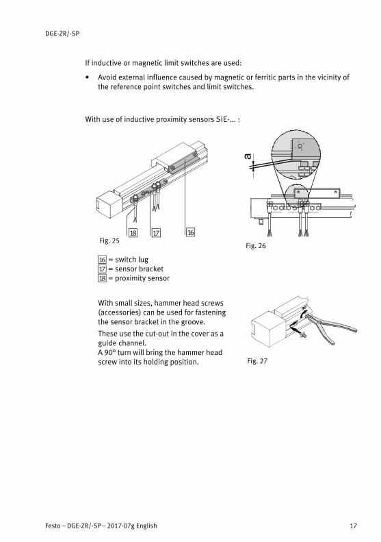
With use of inductive proximity sensors SIE-... :
aF = switch lugaG = sensor bracketaH = proximity sensor
With small sizes, hammer head screws(accessories) can be used for fasteningthe sensor bracket in the groove.
These use the cut-out in the cover as aguide channel.A 90° turn will bring the hammer headscrew into its holding position.
Fig. 25aFaGaH
Fig. 26
Fig. 27

DGE-ZR/-SP
18 Festo – DGE-ZR/-SP – 2017-07g English
If magnetic proximity sensors SME-... areused :
� Use the grooves in accordance withFig. 28.
� Place the proximity switches with nominalsizes 8/12/18 with the cable outlet facingthe centre of the stroke.
For DGE-...-SP:
� Observe that the magnet is situatedasymmetrically on the inner slide (on theside facing away from the motor).
� Avoid external influence caused bymagnetic or ferrite parts in the vicinity ofthe proximity sensors (10 mm distancefrom the slot nuts).
For DGE-25-SP:
� Place the proximity sensor only in the sidegrooves. The magnetic field is very weakin the lower groove.
For DGE-40-SP:
� Place the proximity sensor SMT-8 (highresponse sensitivity) only in the sidegrooves. In the top grooves, the magneticfield is very strong (danger of multipleswitching).
In this way you can ensure that the switches function faultlessly.
Fig. 28
DGE-18-ZR DGE-12-ZR DGE-8-ZR
DGE-63-ZR DGE-40-ZR DGE-25-ZR
DGE-18-SP
DGE-63-SP DGE-40-SP DGE-25-SP

DGE-ZR/-SP
Festo – DGE-ZR/-SP – 2017-07g English 19
Increased protection against consequential damages:
� Use shock absorbers or fixed stops of sufficient size outside the safety limitswitches.
The effective stroke of the product may be shorter, depending on themounting situation.
Carrying out the installation of external accessories
For placement of the proximity sensors:
1. Place the safety limit switches in the mechanical end positions (W) as shownin Fig. 29.
2. Place the hardware limit switches near the mechanical end positions.
At first, the limit switches can still be shifted in the longitudinal direction (cable reserve; for accurate positioning � chapter “Commissioning”).
3. If necessary, place a reference point switch between both hardware limitswitches (exact positioning: � chapter “Commissioning”).

DGE-ZR/-SP
20 Festo – DGE-ZR/-SP – 2017-07g English
� Take into account the following plan for positioning the proximity switches:
M Motor
X Interface to emergency stop circuit
Z Interface to controller
W Mechanical end position
S Switching point of the safety limit switches
S Switching point of the hardware limit switches
R Reference point position
O Positioning limits of the software controller
O/2 Stroke centre
d Length of the switching lug
h Stroke reserve: h = n + r
n Controlled braking path
r Distance of the switching point of the safety limit switches from the
mechanical end position.
x Distance of the reference point switch from the end of the stroke reserve
Fig. 29: Schematic distribution of the proximity switches
WS
n
R
d > h
h=n+r
H
d > xx
O O/2 O
X
Z
r
WS
n
H
rd
DGE-ZR/-SP
Festo – DGE-ZR/-SP – 2017-07g English 21
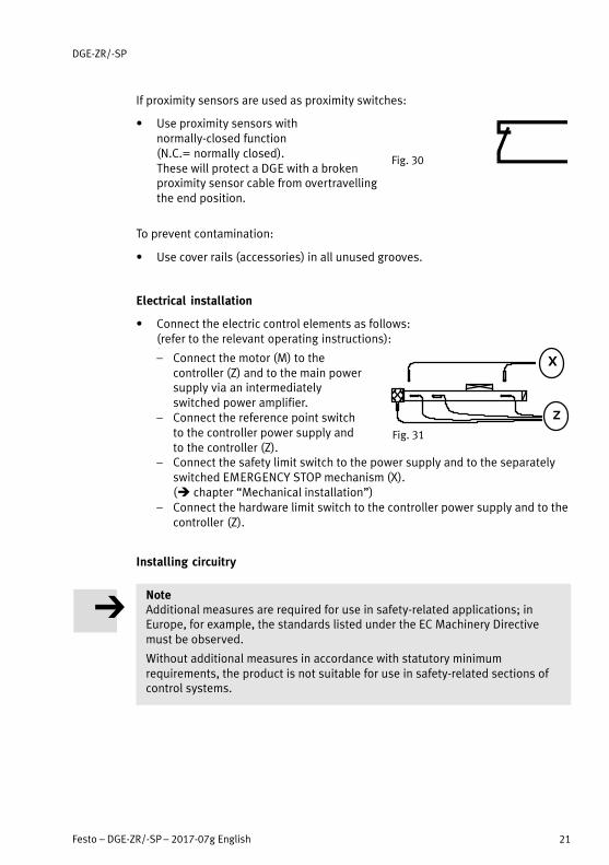
If proximity sensors are used as proximity switches:
� Use proximity sensors withnormally-closed function (N.C.= normally closed).These will protect a DGE with a brokenproximity sensor cable from overtravellingthe end position.
To prevent contamination:
� Use cover rails (accessories) in all unused grooves.
Electrical installation
� Connect the electric control elements as follows:(refer to the relevant operating instructions):
– Connect the motor (M) to thecontroller (Z) and to the main powersupply via an intermediatelyswitched power amplifier.
– Connect the reference point switchto the controller power supply andto the controller (Z).
– Connect the safety limit switch to the power supply and to the separatelyswitched EMERGENCY STOP mechanism (X). (� chapter “Mechanical installation”)
– Connect the hardware limit switch to the controller power supply and to thecontroller (Z).
Installing circuitry
NoteAdditional measures are required for use in safety-related applications; inEurope, for example, the standards listed under the EC Machinery Directivemust be observed.
Without additional measures in accordance with statutory minimumrequirements, the product is not suitable for use in safety-related sections ofcontrol systems.
Fig. 30
Fig. 31
Z
X

DGE-ZR/-SP
22 Festo – DGE-ZR/-SP – 2017-07g English
6 Commissioning
Preparing for commissioning
WarningMoving masses can cause personal injury andmaterial damage (crushing).
� Make sure that, in the positioning range, – nobody can place his/her hand in the path
of the moving components (e.g.�by use of a protective crate),
– there are no foreign objects.It should not be possible to touch the DGE-… until the mass has come to acomplete standstill.
Fig. 32
NoteIncorrect default values of the braking ramp in STOP conditions (e.g. EMERGENCY STOP and quick stop) result in overloading of the linear axisand can damage it or drastically reduce its service life.
� Check the settings for all braking ramps on your controller or the higher-ordercontroller (deceleration values and jerking).
� Taking the travel speed, moveable load and mounting position into account,make sure that the delay values (brake delay and delay times) are set in sucha way that the maximum drive torque or feed force of the linear axis used isnot exceeded.
� Use the “PositioningDrives” sizing software to design the linear axis � www.festo.com.
NoteBlock-step acceleration profiles (without smoothing) cause high peaks in themotive force that can lead to drive overload. In addition, positions outside thepermissible range may occur as a result of overswing effects. A jolt-limitedacceleration specification reduces vibrations in the entire system and has apositive effect on stress in the mechanical system.
� Check which controller settings may be adapted (e.g. jolt limitation andsmoothing of the acceleration profile).
Positioning the limit switches:

DGE-ZR/-SP
Festo – DGE-ZR/-SP – 2017-07g English 23
1. Push the slide at first into a mechanical end position (W).
2. Position the slide the distance of the stroke reserve h away from themechanical end position (� also Fig. 29).
Stroke reserve h (h = n + r)
DGE-... SP ZR
8 – 27.5 mm
12 – 36.5 mm
18 6.5 mm 46.5 mm
25 10 mm 63 mm
40 20 mm 100 mm
63 30 mm 172 mm
Fig. 33: Stroke reserve h
NoteDistance r only needs to be large enough to ensure reliable switching of thesafety limit switches.
If the required braking path a together with the distance r in your application isgreater than the stroke reserve intended by Festo (a+ r > h), you must increasethe stroke reserve at the cost of the effective stroke.
HSW
a
h
r n

DGE-ZR/-SP
24 Festo – DGE-ZR/-SP – 2017-07g English
3. Shift the hardware limit switch for the relevant end position up to itsswitching point in the direction of the slide.
H
h
SIE-... SME-8...Fig. 34
SF
Mag
SF = Switching lugMag = Magnet
4. Fasten the hardware limit switch exactly at this point.
If magnetic proximity sensors SME-... are used :
� Note that the switching magnet on the inner slide is arranged asymmetrically.As a result, the proximity sensors are distributed asymmetrically on the DGE.
5. Repeat the last four points in the other end position.
6. Push the slide into the end positions.
You can then check whether the hardware limit switches function correctly andwhether the switching lug (if available) is seated free of play.
7. Fasten the safety limit switches at point S between the relevant mechanicalend position (W) and the nearby hardware limit switch.
The following then applies:
– A braking path of length n remains between the response point of thehardware limit switch and the response point of the safety limit switch.
– The response ranges (grey bars in Fig. 35) of the safety limit switch (SS) andthe hardware limit switch (HW) overlap. In this way you can avoidundefined operating states when the axis is switched on.
– In spite of the defined end position S being overrun, the safety limitswitches remain actuated up to the mechanical end position.
– If the slide is set correctly, it will brake completely when overrunning ahardware limit switch before the safety limit switch responds.

DGE-ZR/-SP
Festo – DGE-ZR/-SP – 2017-07g English 25
HW
SS
REF
WS
n
RH
x
r
WS
n
H
r
O O/2 O
Fig. 35
REF = Reference point switchHW = hardware limit switchSS = safety limit switch
8. Fasten the reference point switch (if necessary) between the hardware limitswitches under the following condition:
There must be a point at which both the reference point switch as well as thehardware limit switch near the motor respond simultaneously (x < d, � Fig. 29).
Checking the functions:
1. Push the slide into a mechanical end position.
2. Check whether the safety limit switches and the reference point switchesfunction correctly and whether the switching lug is seated free of play.
� Repeat the points 1 – 2 in the other end position.

DGE-ZR/-SP
26 Festo – DGE-ZR/-SP – 2017-07g English
Carrying out commissioning
1. Check travel 2. Homing 3. Test run
Determining the approachdirection of the motor
Comparing the real situationwith the image in thecontroller
Checking the overallbehaviour
Fig. 36: Definitions
1. Start check travel limited to low dynamics. In spite of equal control, motors of the same type sometimes turn in theopposite direction due to the circuitry. The DGE-...-SP has a clockwise-rotating spindle: When the drive shaft isrotated clockwise, the slide moves in the direction of the motor.
2. Start homing in accordance with the operating instructions for your motordrive system limited to low dynamics up to the reference switch.
3. Start a test run and limit it to low dynamic response.
4. Check whether the DGE-... fulfils the following conditions:
– The slide must be able to move through the complete intended positioningcycle.
– The slide must stop as soon as it reaches a limit switch.
5. If the proximity sensors do not respond: � chapter�11 “Eliminating malfunctions” and the operating instructions forthe proximity sensors.
In the case of deviations from the nominal behaviour:
� Check these points on your installation:
– Motor– Mechanical mounting– Electrical connections(� also chapter “Eliminating malfunctions”).
DGE-ZR/-SP
Festo – DGE-ZR/-SP – 2017-07g English 27
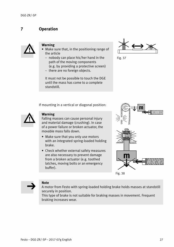
7 Operation
Warning� Make sure that, in the positioning range of
the article– nobody can place his/her hand in the
path of the moving components (e.g.�by providing a protective screen)
– there are no foreign objects.
It must not be possible to touch the DGEuntil the mass has come to a completestandstill.
If mounting in a vertical or diagonal position:
WarningFalling masses can cause personal injury and material damage (crushing). In case of a power failure or broken actuator, themovable mass falls down.
� Make sure that you only use motors with an integrated spring-loaded holdingbrake.
� Check whether external safety measuresare also necessary to prevent damage from a broken actuator (e.g.�toothedlatches, moving bolts or an emergencybuffer).
NoteA motor from Festo with spring-loaded holding brake holds masses at standstillsecurely in position.This type of brake is not suitable for braking masses in movement. Frequentbraking increases wear.
Fig. 37
Fig. 38

DGE-ZR/-SP
28 Festo – DGE-ZR/-SP – 2017-07g English
If the motor turns in the wrong direction:
NoteWhen the motor is dismounted (e.g. turning the motor), the reference positionis lost.
� Start homing as detailed in the chapter “Commissioning” in order to set thenew reference position.
8 Service and maintenance
WarningController signals can cause the DGE to make unintentional movements.
� Switch off the controller for all maintenance work on the DGE and secureit to prevent it from being switched back on unintentionally.
� Do not change screws and threaded pins if there is no direct request to do thisin these operating instructions.
� If necessary, clean the cover band with a soft cloth.
The following cleaning agents are permitted: all non-abrasive cleaning agents.
� Grease the surfaces of the guide rail or cover band if they no longer have a layer of grease.Grease: in accordance with Fig. 41.
In this way you will renew the protection against humidity.
� Recommendation:Return the DGE-...-ZR to Festo for inspection after every 5000 kilometres run.
Fig. 39

DGE-ZR/-SP
Festo – DGE-ZR/-SP – 2017-07g English 29
Lubricating the roller bearing guides DGE-...-KF:
� Observe the lubricating intervals:
– With roller bearing cassettes of the old design (A): every 400 kilometres run
– With roller bearing cassettes of the new design (B), the lubricating intervalsdepend on the lubricant used:
Lubricant type 1st interval 2nd ... nth interval
Festo special grease LUB-KC1
5000 km 400 km
Rhenus Norlith STM 2(Rhenus Lub GmbH & Co. KG)
5000 km DGE-8 ... 18: 400 kmDGE-25 ... 63: 5000 km
Gearmaster LXG 00(Fuchs Lubritech GmbH)
5000 km DGE-8 ... 18: 5000 kmDGE-25 ... 63: not permitted
Fig. 41: Lubrication types and intervals
� Note that lubrication intervals must beshortened in the case of:
– Dusty and contaminated environment– With rated strokes > 2000 mm
or < 50 mm– At speeds of > 2 m/s– If the DGE > is more than 3 years old
� Grease the slide bearings at all lubricationnipples 6. Special grease and grease gunwith needle pointed nozzle: see chapter“Accessories”.
� Move along the entire path of travel whilegreasing so that the grease is distributedevenly.
Fig. 40
(A)
(B)
Fig. 42
DGE-18-KF
DGE-...-KF
6
6

DGE-ZR/-SP
30 Festo – DGE-ZR/-SP – 2017-07g English
Each time maintenance is carried out:
� Make sure that the slide is set free of playand distortion.Fig. 43 shows the critical points.
Increasing the tension of the cover band for guaranteeing the IP protection class (if necessary with a second person):
ÓÓ
Fig. 44
1. Push the slide into an end position.
2. Remove the cover cap (if present) from the opposite side (� Fig. 44).
3. Unscrew the threaded pins a little.
4. With the aid of flat pliers, pull the cover band until it just begins to lift up theblack wiper strip.
5. Tighten the threaded pins again.
Rated @ Tightening torque
8/12/18 1 Nm
25/40 2 Nm
63 3 Nm
6. Press the cover cap tight again.
Fig. 43
1. 3.
2.

DGE-ZR/-SP
Festo – DGE-ZR/-SP – 2017-07g English 31
9 Repair
NoteFor DGE-...-ZR:
Retensioning of the toothed belt reduces its service life considerably.
In addition, the technical specifications, e.g. the feed constant, will bemodified.
� Make sure that the toothed belt has not been retensioned.The toothed belt is pretensioned so that it does not have to be retensionedduring its life.
� Recommendation: Return the DGE to our repair service. The necessary fine adjustments and tests will then be taken especially intoaccount.
� Information on spare parts and aids can be found under:www.festo.com/spareparts
10 Accessories
Note� Please select the appropriate accessories from our catalogue
www.festo.com/catalogue
Designation Type Part number/manufacturer
Grease gun with pointed nozzle LUB-1 647 958 *)
Lubrication adapter (if little space) LUB-1-TR-L 647 960 *)
Special grease (silicone-free)
Special grease (silicone-free)
Special grease (silicone-free)
LUB-KC1
RhenusNorlith STM 2
GearmasterLXG 00
from Festo *)
Rhenus Lub GmbH & Co. KG
Fuchs Lubritech GmbH
*) � Spare-parts catalogue under www.festo.com/spareparts

DGE-ZR/-SP
32 Festo – DGE-ZR/-SP – 2017-07g English
11 Eliminating malfunctions
Malfunction DGE-... Possible cause Remedy
Inaccurate positioning
SP, ZR Axial play on the slide Tighten axial slide screws (2)
ZR Tooth skipped due to highinertial forces
Reduce dynamic loading,new homing, if necessaryreturn the DGE to Festo
SP Thrust bearing worn
ZR Toothed belt damaged
SP, ZR Reference point switchloose
Fasten reference pointswitch
SP Spindle nut worn Send in the DGE
SP, ZR Outside the axis Check peripherals (e.g. motor, controller...)
Heavy abrasionon the coverband
SP, ZR Cover band tensioned tootightly
Re-tensioning the coverband
Loud runningnoises
SP, ZR Axial play in the fixedbearing; wear on the driveshaft
Return the DGE to Festo
SP, ZR Insufficient lubrication (of the slide bearing)
Lubricate again, if necessaryreturn the DGE to Festo
ZR Toothed belt damaged Return the DGE to Festo

DGE-ZR/-SP
Festo – DGE-ZR/-SP – 2017-07g English 33
Malfunction RemedyPossible causeDGE-...
Missing orundefinedswitchingfunctions
SP, ZR Proximity sensor or cabledefective
Install new proximity sensoror replace cable
Switching magnet loose orbroken
Return the DGE to Festo
Proximity switch installed inimpermissible groove
Use permissible groove
Sensing distance setincorrectly
Readjust
Incorrect switch or incorrectconnection
Use correct switch orconnection
25-SP Proximity sensors do notswitch in the lower groove
Place proximity sensors inthe side groove
40-SP Proximity sensors switchmultiple times in the uppergroove
Place proximity sensors inthe side groove
Rotarymovement ofmotor is nottransferred tothe DGE-...
SP, ZR Clamping hub of thecoupling spins
Check installation of themotor mounting kit(coupling)
SP Spindle nut loose Return the DGE to Festo
ZR Toothed belt broken
Cover band liftsup
SP, ZR Incorrect tensioning of thecover band
Re-tension cover band
Cover banddamaged orbent
SP, ZR External influences,mechanical overloading
Return the DGE to Festo
Slide jams SP Spindle nut worn
SP Ball screw drive blocked incase of continuous reversingoperation with shortstrokes.
Occasionally run themaximum stroke to achieveeven distribution of the ballsin the spindle nut again.

DGE-ZR/-SP
34 Festo – DGE-ZR/-SP – 2017-07g English
12 Technical specifications (not valid for DGE-...-RF)
Toothed belt type DGE -8-ZR -12-ZR -18-ZR -25-ZR -40-ZR -63-ZR
Design Electrical linear unit with circulating toothed belt
Permitted temperaturerange
-10 ... +40 °C (storage/operation)
Mounting position Any
Permissible effectiveload:
horizontalvertical
1.5 kg0.5 kg
3 kg1.3 kg
6 kg2.4 kg
20 kg10 kg
50 kg25 kg
120 kg60 kg
Protection class **) IP40 (cover band on top/lateral), IP42 (cover band underneath)
Feed constant ***) 32mm/rev
38mm/rev
52mm/rev
63mm/rev
100mm/rev
176mm/rev
Max. permitted torque *) 0.076� Nm 0.18 Nm 0.5 Nm 2.6 Nm 9.7 Nm 42.0 Nm
Max. feed force (theoretical)*)
15 N 30 N 60 N 260 N 610 N 1500 N
Max. radial force on the drive shaft ****)
Stability calculation:For 5000 km operation:For 10,000 km operation:
103 N56 N40 N
77 N96 N70 N
290 N117 N80 N
307 N235 N140 N
984 N370 N170 N
2600 N840 N400 N
Max. permitted slide speed *)
1 m/s 1.5 m/s 2 m/s 5 m/s (3 m/s)
Permitted linear acceleration *)
depends on mass

DGE-ZR/-SP
Festo – DGE-ZR/-SP – 2017-07g English 35
Toothed belt type DGE -63-ZR-40-ZR-25-ZR-18-ZR-12-ZR-8-ZR
Mass moments ofinertia [kgmm2]
Mass moment of inertia JA related to drive shaft:JA = J0 + H � JH + JK + m � JL + i � JWStroke length (H), effective load (m), number of additional slides (i)
for zero stroke (J0) 0.56 (2.451)
1.45 (5.81)
6.376 (24.72)
38 (81)
234 (525)
2560 (5070)
per metre stroke (JH) 0.342 0.877 2.101 7.8 45 360
per kg work load (JL) 25.91 36.54 68.48 100 253 785
of the coupling (JK) 0.13 0.47 6.06 42.3 417
per additional slide (JW) – – (17) (38) (268) (2434)
Repetition accuracy as per DIN 230, part 2 {R = ±2s}
±0.08 mm(for stroke lengths < 1,000 mm)
±0.1 mm(for stroke lengths < 2000 mm)
( ) Values in brackets apply to DGE-...-KFSpecifications without additional parenthesized value apply to DGE without guideand DGE-...KF
*) for expected service life**) for stroke lengths < 660 mm with DGE-8-...; otherwise for stroke lengths < 1000 mm***) This is a nominal value and varies due to component tolerances.****)- The point of application of the radial force is at the journal end
- The values refer to a radial force on a journal- The radial force for the corresponding operation performance is determined by the basic load rating of the bearing.

DGE-ZR/-SP
36 Festo – DGE-ZR/-SP – 2017-07g English
Spindle types DGE -18-SP -25-SP -40-SP -63-SP
Design electrical linear unit with driven spindle
Permitted temperature range 0 ... +40 °C (storage/operation)
Mounting position Any
Permissible effective load: horizontalvertical
6 kg3 kg
25 kg10 kg
50 kg25 kg
150 kg75 kg
Protection class **) IP40 (cover band on top/lateral), IP42 (cover band underneath)
Feed constant ***) 4 mm/rev 10 mm/rev 20 mm/rev 30 mm/rev
Max. permitted torque *) 0.1 Nm 0.45 Nm 2.1 Nm 8.5 Nm
Max. feed force (theoretical) *)
140 N 250 N 600 N 1600 N
Max. radial force on the drive shaft ****)
40 N 75 N 250 N 800 N
Max. permitted slide speed *) 0.2 m/s 0.5 m/s 1.0 m/s 1.2 m/s
Max. permitted linear acceleration *)
6 m/s2

DGE-ZR/-SP
Festo – DGE-ZR/-SP – 2017-07g English 37
Spindle types DGE -63-SP-40-SP-25-SP-18-SP
Mass moments of inertia[kgmm2]
Mass moment of inertia JA related to drive shaft:JA = J0 + H � JH + JK + m � JL + i � JWStroke length (H), effective load (m), number of additional slides (i)
for zero stroke (J0) 0.74 (0.83) 2.87 (3.95) 36.4 (48) 315 (388)
per metre stroke (JH) 3.1 12.1 100 667
per kg work load (JL) 0.405 2.53 10.1 22.8
of the coupling (JK) 0.13 6.06 6.06 42.3
per additional slide (JW) (0.1) (0.96) (10.7) (70.7)
Repetition accuracy as perDIN 230 part 2 {R = ±2s}
±0.02 mm
( ) Values in brackets apply to DGE-...-KFSpecifications without additional parenthesized value apply to DGE without guide and DGE-...KF
*) for expected service life**) for stroke lengths < 1000 mm***) This is a nominal value and varies due to component tolerances.****) The point of application of the radial force is at the journal end.

DGE-ZR/-SP
38 Festo – DGE-ZR/-SP – 2017-07g English
Materials DGE-... 18-SP 25 ... 63-SP 8 ... 18-ZR 25 ... 63-ZR
Piston Al Al PA Al
Slide, cylinder barrel, cover Al
Ball bearing, stop, sliding blocks,roller cassette, cover band
St
Buffer, wiper strip, O-rings Perbunan, AU POM, AU Perbunan Rubber, POM, AU
Guide rings, band guide POM-PE
Lead screw spindle St, POM, MS St – –
Guide rail Steel (25 ... 40: corrosion resistant, coated)
Toothed belt – – Polychloroprene, nylon, GF
Toothed discs – – St
[N] / [Nm]
Forces and torques

DGE-ZR/-SP
Festo – DGE-ZR/-SP – 2017-07g English 39
DGE-...-SP* 18 25 40 63
Fzmax. 1.8 2 15 106
Mymax. 0.8 1.5 4 18
Mxmax. 0.5 1 4 8
Mzmax. 0.8 1.5 4 18
MyMymax
�MzMzmax
�FzFzmax
� 1 MxMxmax
� 1* without guide Fy � 0
DGE-...-ZR* 8 12 18 25 40 63
Fzmax. [N] 38 59 120 330 800 1600
Mymax. [Nm] 2 4 11 20 60 120
Mxmax. [Nm] 0.15 0.3 0.5 1 4 8
Mzmax. [Nm] 0.3 0.5 1 3 8 24
MyMymax
�MxMxmax
� 0.2 x MzMzmax
� 0.4 x FzFzmax
� 1
MzMzmax
� 1 FzFzmax
� 1* without guide
Fy � 0
DGE-...-ZR-KFDGE-...-SP-KF
8–
12–
1818
2525
4040
6363
Fzmax.Fymax.
255 565 930 3080 7300 14050
Mzmax.Mymax.
3.5 9 23 85 330 910
Mxmax. 1 3 7 44.5 170 580
MyMymax
�MxMxmax
�MzMzmax
�FyFymax
�FzFzmax
� 1Vmax 3 m/s

Reproduction, distribution or sale of this document or communication of its contents to others without express authorization isprohibited. Offenders will be liable for damages. All rights reserved in the event that a patent, utility model or design patent isregistered.
Copyright:Festo AG & Co. KGRuiter Straße 8273734 EsslingenGermany
Phone:+49 711 347-0
Fax:+49 711 347-2144
E-mail:[email protected]
Internet:www.festo.com